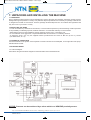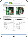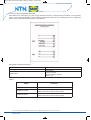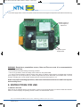
1
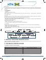
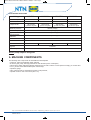
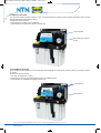
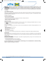
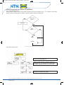
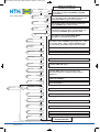
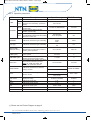
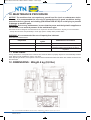
Manuel utilisation IN PULSE en:Manuel utilisation 04/05/11 15:49 Page1 IN’PULSE Oil Lubrication Electro-Pump User and Maintenance Manual Warranty information Manual drawn up in accordance with EC Directive 2006/42 Pour obtenir ce manuel d'utilisation en français, veuillez consulter notre site Internet : www.ntn-snr.com Um unsere deutsche Gebrauchsanweisung zu erhalten, besuchen Sie uns auf unserer Homepage: www.ntn-snr.com Para conseguir este libro de instrucciones en español, consultar nuestro sitio Internet : www.ntn-snr.com Per ricevere questa guida utente in italiano, si prega di visitare il nostro sito Web: www.ntn-snr.com Siège social : NTN-SNR ROULEMENTS - Rue des Usines - 74000 Annecy - FRANCE - RCS Annecy B 325 821 072 Code APE 2815Z - Code NACE 28.15 www.ntn-snr.com 1 Manuel utilisation IN PULSE en:Manuel utilisation 04/05/11 15:49 Page2 1. TABLE OF CONTENTS 1.Table of contents 2.Introduction 3.General description 4.Product-machine identification 5.Technical specifications 6.Machine components 7.Unpacking and installing the machine 8.Instructions for use 9.Troubleshooting p.2 p.2 p.2 p.3 p.3 p.4 p.6 p.9 p.14 10.Maintenance procedure 11.Disposal 12.Dimensions 13.Handling and transportation 14.Operating hazards 15.Contraindications 16.Warranty information 17.Declaration of conformity p.15 p.15 p.15 p.16 p.16 p.16 p.17 p.18 2. INTRODUCTION This user and maintenance manual refers to the IN’PULSl lubrication system. This manual should be conserved in such a way that it remains undamaged over time and is readily available to personnel needing to consult it. The manufacturer reserves the right to update the product and/or the user and maintenance manual without the obligation to revise previous versions.Further copies of this manual, updates or clarifications can be obtained by directly contacting Experts & Tools at NTN-SNR Roulements, or to consult our web site at www.ntn-snr.com. The use of the equipment referred to in this manual must be entrusted to qualified personnel with a basic knowledge of mechanics, hydraulics and electrical systems. It is the responsibility of the installer to use tubing suitable for the system; the use of inadequate tubing can cause problems with the pump, injury to persons and create pollution. Loosening of connections can cause serious safety problems; carry out a check before and after installation and, if necessary retighten them. Never exceed the maximum working pressure values permitted for the panel and the components connected to it. Before any maintenance or cleaning operation disconnect the power supply, close off the airsupply and discharge the pressure from inside the equipment and the tubing connected to it. Do not subject the panel, the connections, the tubing or parts under pressure to violent impacts; damaged tubing or connections are dangerous and should be immediately replaced. After long periods of inactivity check air tightness of all parts subjected to pressure. Personnel must use personal protection equipment, clothing and tools adequate for the location and the use of the panel both during its operation and during maintenance operations. The panel, and any accessories mounted on it, should be carefully checked immediately on receipt and in the event of any discrepancy or complaint the NTN-SNR Roulements Sales department should be contacted without delay. NTN-SNR Roulements declines to accept any responsibility for injuries to persons or damage to property in the event of the non-observance of the information presented in this manual. Any modification to component parts of the system or the different destination of use of this system or its parts without prior written authorization from NTN-SNR Roulements will absolve the latter from any responsibility for injury to persons and/or damage to property and will release them from all obligations arising from the guarantee. 3. GENERAL DESCRIPTION Oil lubrication pump IN’PULSE has been designed for industry machine tools.The electric gear pump is designed to work with LUBSO INJECT ou LUBSO MANIFOLD. IN’PULSE is available in two versions: - Manual IN’PULSE, manually controlled or via the PLC of the machine tool; - Automatic IN’PULSE (or programmable), automatically controlled via a built-in controller. 3.1 LUBRICATION CONTROL SYSTEM - PRINCIPLES OF OPERATION Automatic IN’PULSE operates on the principle of intermittent lubrication which involves the following three steps: - Prelube - Lube (lube – wait) - Standby Siège social : NTN-SNR ROULEMENTS - Rue des Usines - 74000 Annecy - FRANCE - RCS Annecy B 325 821 072 Code APE 2815Z - Code NACE 28.15 www.ntn-snr.com 2 Manuel utilisation IN PULSE en:Manuel utilisation 04/05/11 15:49 Page3 3.1.1 Prelube This step is made up of a set of cycles (max 999 cycles) during which the lubrication system runs a series of lubrication cycles (lubrication will be described in paragraph 3.1.2) necessary to vent air from the pump and check lubrication functions. Prelube takes place: - on POWER-ON; - on RESET; - Any time new parameters are set. When prelube is set to “0”, Intermittent Lubrication will only consist in the lube – standby/standby - lube phases (see START mode). 3.1.2 Lube This step is made up of a set of cycles (max 999 cycles) during which lubrication is carried out. Each cycle consists of two sub-cycles (lube and wait) and involves the monitoring of timers and/or inputs: - during lube, system delivers lubricant to the lubrication points; - during wait, a timer defines the wait time between two lube cycles or before the beginning of the standby phase (in case only 1 lube cycle was set). There are three types of lube: - TIMER: Lubricant delivery is simply regulated by a timer; - PS: Lubricant delivery is carried out only if the system is under pressure; 3.1.3 Standby During this step lubrication system is idle until the next lubrication cycle. There are three ways to regulate standby: - TIMER: a timer regulate system idling; - PULSE: a pulse counter regulate system idling; - BOTH: both a timer and a pulse counter regulate system idling. The type of standby will depend on which of these two events will start first. Lubrication Pre lubrication Pause Pause Pause Pause Wait Pomp on 4. PRODUCT-MAChINE IDENTIFICATION Machine identification yellow label is located on the side of the reservoir and contains product serial number, input voltage and details of the operating parameters. 5. TEChNICAL SPECIFICATIONS 5.1 GENERAL TEChNICAL SPECIFICATIONS Lubricant Minral Oil Lubricant Viscosity at usage temperature Working Temperature Storage Temperature Working Humidity Mechanical Protection Grade Sound Pressure Level 68 to 320 cSt (320 to 1480 SUS) +5°C to + 60°C (+41°F to +140°F) - 20°C to + 60°C (-4°F to +140°F) 90% max IP-55 <70 dB (A) Siège social : NTN-SNR ROULEMENTS - Rue des Usines - 74000 Annecy - FRANCE - RCS Annecy B 325 821 072 Code APE 2815Z - Code NACE 28.15 www.ntn-snr.com 3 Manuel utilisation IN PULSE en:Manuel utilisation 04/05/11 15:49 Page4 5.2 ELECTRIC GEAR PUMP Voltage Power absorption 110V/50hz 110V/60hz 230V/50hz 230V/60hz 162W 155 W 150W 148W 0.69A 0,70A 180 cm³/min (10.98 cu.in.)/min 220 cm³/min (13,45 cu.in.)/min Nominal current Pump flow rate 1.48A 180 cm³/min (10.98 cu.in.)/min 220 cm³/min (13.42 cu.in.)/min Maximum pressure 30 bars (411psi) Reservoir capacity 3 litres (0.66 gals) By-pass calibration 25 bars (367.5 psi) Pressure Switch calibration 18 bars (264.6 psi) Insulation Class B Rotation direction Revolutions/min Max continuous working time Min standby time Clockwise 2900 3500 2900 3500 2 minutes 5 times MIN setup time NOTE: pump output is energized. 6. MAChINE COMPONENTS The following main components are assembled to the baseplate: - A reservoir, made of transparent plastic material; - An electric gear pump, with high performance and minimum power consumption; - A level sensor, which indicates lubricant minimum level via a N.O. electric contact (reservoir empty). To reverse N.O. to N.C., please contact NTN-SNR Experts & Tools Dept.; - A pressure gauge; - A N.O. pressure switch, which detects system under pressure; - A printed circuit for user connections (see 7.4.2) Siège social : NTN-SNR ROULEMENTS - Rue des Usines - 74000 Annecy - FRANCE - RCS Annecy B 325 821 072 Code APE 2815Z - Code NACE 28.15 www.ntn-snr.com 4 Manuel utilisation IN PULSE en:Manuel utilisation 04/05/11 15:49 Page5 6.1 MANUAL IN’PULSE The electronic board, located under the cover of manual IN’PULSE, allows pressure switch and electric level contact management both independent or serial. On the front panel there are: - Push-button for manual control, “MANUAL” - LED indicator for “PUMP ON”. (Green, normally off) LED indicator Push-button for manual control 6.2 AUTOMATIC IN’PULSE The controller, located under the cover of automatic IN’PULSE, allows a total pump autonomy both in cycle times, alarms or checks. On the front panel there are: - LCD with 16 characters x 2 lines - Push-buttons: three for control/management and one RESET button - LED indicator for “POWER ON” (Green, always on) Push-buttons Reset button Siège social : NTN-SNR ROULEMENTS - Rue des Usines - 74000 Annecy - FRANCE - RCS Annecy B 325 821 072 Code APE 2815Z - Code NACE 28.15 www.ntn-snr.com 5 Manuel utilisation IN PULSE en:Manuel utilisation 04/05/11 15:49 Page6 7. UNPACKING AND INSTALLING ThE MAChINE 7.1 UNPACKING Once a suitable location has been found to install the unit, remove the pump from package. Check the unit has not been damaged during transportation or storage. No particular disposal procedures are necessary as package materials are no dangerous for health or environment. However, package should be disposed of in accordance with regulations that may be in force in your area or country. 7.2 INSTALLING ThE PUMP - In order to facilitate any maintenance intervention, to avoid unnatural posture for personnel during machine operation or the possibility of sustaining impacts, install the machine in a comfortable and easy-to-reach location. - Allow sufficient space for the installation, leaving minimum 100 mm (3.9 in.) around the unit. - Do not install the unit in aggressive or explosive/inflammable environments or on vibrating surfaces. - To install the pump, use only the supplied bracket provided with two holes for Ø6 mm (Ø 0.2 in.) screws (see Dimensions, ch. 12). 7.3 hYDRAULIC CONNECTION Connect IN’PULSE to the system via the hydraulic connection located on the baseplate, on the right side of the pump: standard thread ¼ BSP. 7.4 ELECTRIC WIRING 7.4.1 Electric diagram Here follows the general electric diagram for both automatic and manual IN’PULSE: NOTICE: Pressure can be monitored by a micro-switch or a NPN/PNP proximity sensor. Siège social : NTN-SNR ROULEMENTS - Rue des Usines - 74000 Annecy - FRANCE - RCS Annecy B 325 821 072 Code APE 2815Z - Code NACE 28.15 www.ntn-snr.com 6 Manuel utilisation IN PULSE en:Manuel utilisation 04/05/11 15:50 Page7 7.4.2 User connections The following picture shows the printed circuit for user connections, where the user has to connect power supply and external outputs for the correct functioning of both automatic and manual IN’PULSE. For details about connections, please refer to special paragraphs. (Printed circuit serigraphy only refers to automatic IN’PULSE. For the manual version there is a white label as showed in Fig. 2) M2 OUTLET 6 - 7 ONLY FOR AUTOMATIC IN’PULSEe2 M1 Fig. 1 Automatic version Fig. 2 Manual version 7.4.3. Connections for manual IN’PULSE Here follows user connections for power supply (terminal M1), pressure-switch and electric level contact (independent or serial), and the manual push-button (terminal M2). Furthermore, it is also shown how to change the type of connection (independent or serial) for the pressure-switch and electric level contact, by acting on the jumper located on the electronic board of manual IN’PULSE. SERIAL CONNECTIONS PRESSURE-SWITCH AND MINIMUM LEVEL INDEPENDANT CONNECTIONS PRESSURE-SWITCH AND MINIMUM LEVEL Siège social : NTN-SNR ROULEMENTS - Rue des Usines - 74000 Annecy - FRANCE - RCS Annecy B 325 821 072 Code APE 2815Z - Code NACE 28.15 www.ntn-snr.com 7 Manuel utilisation IN PULSE en:Manuel utilisation 04/05/11 15:50 Page8 7.4.4 Connections for automatic IN’PULSE Here follows user connections for power supply (terminal board M1), external alarm (terminals 6-7) and proximity sensor or micro-switch (terminals 8-9-10). These last terminals have the function of stopping the timer or to register the pulse in order to define the standby duration. (See table A). Input/output electrical specifications: Power Input signal See: 5.1 General technical specifications PNP proximity or N.O. free contacts input. Free contact: 250VAC –150 mA 125VAC/110VDC –300 mA 30VDC –1A Alarm Output Table A : Mode Function STAND BY TIMER Stops the timer for standby duration STAND BY PULSE Decrements the pulse counter that defines standby duration (this function doesn’t stop the timer) STAND BY BOTH Decrements the pulse counter that defines standby duration (this function doesn’t stop the timer) Siège social : NTN-SNR ROULEMENTS - Rue des Usines - 74000 Annecy - FRANCE - RCS Annecy B 325 821 072 Code APE 2815Z - Code NACE 28.15 www.ntn-snr.com 8 Manuel utilisation IN PULSE en:Manuel utilisation 04/05/11 15:50 Page9 7.4.5 Power supply switch of the screen printed circuit board and screen brightness adjustment (Automatic IN’PULSE only) Variable resistor for screen brightness adjustment Jumpers for power supply switch WARNING: Each time a powerfailure occurs, Date and Time are reset. It is recommended to setup Date and Time. 7.4.6 Precautions to be taken during connecting procedure ⇒ Prior to any operation, check the voltage of the machine on the product label. ⇒ In order to prevent dangers of electric shocks due to direct or indirect contact with the energized parts, electrical power supply line must be protected by a suitable magnetothermal 30mA differential circuit breaker with 1 second minimum operating time. Circuit breaker capacity must be 10 kA and nominal power In 4 A. At the end of all connecting operations, make sure that hoses and wires are safe from impacts and carefully fixed. 8. INSTRUCTIONS FOR USE 8.1 MANUAL IN’PULSE When the unit is equipped with the manual system, located on the frontal side panel you find the PUMP-ON indicator which is on when the pump is operating. Remote control is via external timer or PLC. Siège social : NTN-SNR ROULEMENTS - Rue des Usines - 74000 Annecy - FRANCE - RCS Annecy B 325 821 072 Code APE 2815Z - Code NACE 28.15 www.ntn-snr.com 9 Manuel utilisation IN PULSE en:Manuel utilisation 04/05/11 15:50 Page10 WARNING: Manual control device (reset button) connects the common signals that can be used as remote indication to PLC (or to another control system). It can be used, for instance, as indication to restart the lube cycle or to cancel an error on the pump. Max power absorption is 400mA. 8.2 AUTOMATIC IN’PULSE When the unit is equipped with an automatic control, all the pump functions and checks are carried out through the builtin controller, alarms and external signals included. Timers are also controlled by the system. For details about machine operation, please refer to par. 8.4. 8.3 Machine operations 8.3.1 Prior to machine start-up - Verify the unit is undamaged. - Check that hydraulic and electric connections have been carefully carried out. - Refill the reservoir with compatible lubricant. - Verify the voltage: MAX 230VAC. RESERVOIR REFILL Use ONLY compatible lubricant and refill the reservoir by means of the oil refill plug provided with a filter. Do not pour lubricant directly into the reservoir without using this oil refill plug. 8.3.2 Machine start-up In order to avoid damage to the machine, the unit must start operating at a minimum working temperature of +5°C (+41°F). - Switch ON the unit (Green LED on) - Verify unit start-up. - Verify piping are air-bubble-free. - Adjust pressure. - Set-up machine parameters. - Verify machine correct operation: pump must carry out lubrication correctly and according to parameters setup. AIR VENTING Pump well-functioning is not affected by presence of air in the system. However, it is advisable to vent air by starting the pump until lubricant comes out air-bubbles-free. (It is recommended to avoid pump operation when lubricant is below the minimum level). PRESSURE REGULATION Pressure can be verified via pressure gauge. It is possible to regulate pressure by acting on the screw located on the frontal side of the baseplate. ⇒ To increase pressure: turn the screw clockwise. ⇒ To decrease pressure: turn the screw anticlockwise. In case of doubts as to correct machine functioning, it is recommended to contact our Eng. Dept. to request testing procedures. Siège social : NTN-SNR ROULEMENTS - Rue des Usines - 74000 Annecy - FRANCE - RCS Annecy B 325 821 072 Code APE 2815Z - Code NACE 28.15 www.ntn-snr.com 10 Manuel utilisation IN PULSE en:Manuel utilisation 04/05/11 15:50 Page11 8.4 IN’PULSE WITh BUILT-IN CONTROLLER OPERATION 8.4.1 Typical working session Notice: prelube is always carried out according to prelube cycles set-up: if prelube cycles = ‘0’, no prelube is run and the system will start operating either in standby or lube according to the pre-set start mode. Pre lub. cycle ? Pre lub. Lub. cycle ? Wait Pause 8.4.2 Typical system start-up PRELUBE will be carried out only when prelube cycles are set (PRELUBE ≠ 0). Whether prelube has been completely carried out (PRELUBE ≠ 0) or no prelube was set (PRELUBE = 0), LUBE or STANDBY will start (see start mode). During standby, you can also see date and time when the function is enabled (see setup). Siège social : NTN-SNR ROULEMENTS - Rue des Usines - 74000 Annecy - FRANCE - RCS Annecy B 325 821 072 Code APE 2815Z - Code NACE 28.15 www.ntn-snr.com 11 Manuel utilisation IN PULSE en:Manuel utilisation 04/05/11 15:50 Page12 SET UP? YES 8.4.3 Setup session NO LUBE Time SET 00m05s NEXT STANDBY SET 01m00s NEXT STANDBY SET 99i NEXT To modify STANDBY Time, when this function is controlled by a timer. This parameter can be set only if STANDBY type is timer or both. To modify STANDBY pulse when this function is controlled by a pulse register. This parameter can be set only if STANDBY type is pulse or both. EXTENDED MENU? YES NO STANDBY MINUTEUR Disabled NEXT To select LUBE Type: Timer – PS DELAY Time SET 00m10s NEXT LUBE Cycles SET 2i NEXT PRELUBE SET 0i NEXT WAIT Time SET 00m10s NEXT START SET IN LUBRIC NEXT ALARM SET Norm.Open NEXT Date & Time SET Day SET Press YES to enter the EXTENDED MENU. Press NO to re-initialize the machine. Press SET to enter STANDBY Type setup; use “-“ and “+” to select Timer – Pulse - Both and SAVE to save the new setting. Push NEXT to go to the next setup. LUBE Type MIN UTEUR Date & Time SET BACK TO STANDBY OR ALARM (IF ACTIVATED) Press YES to enter SETUP. Press NO to go back to STANDBY or ALARM (if activated). Press SET to enter LUBE Time setup; use “-“ and “+” to change the value and SAVE to save the new setting. Push NEXT to go to the next setup. Enabled NEXT 1 NEXT ONLY for PS: To modify DELAY Time for pump-OFF. To modify LUBE Cycle. To modify PRELUBE Cycle. To modify WAIT Time for the next lube cycle. Note: this parameter is displayed only if Lube or Prelube ≠ 0 Sélectionner START mode : “START IN LUBRIC” / “START IN STANDBY”. To select the type of alarm electric contact: Norm. Close/ Norm.Open.”. To enable/disable Date and Time function. To set the day (DATE). Month SET 1 NEXT To set the month (DATE). Year SET 2004 NEXT To set the year (DATE). Hour SET 0 NEXT To set the hour (TIME). Minute SET 0 NEXT To set the minutes (TIME). MAChINE RE-INITIALIZATION Siège social : NTN-SNR ROULEMENTS - Rue des Usines - 74000 Annecy - FRANCE - RCS Annecy B 325 821 072 Code APE 2815Z - Code NACE 28.15 www.ntn-snr.com 12 Manuel utilisation IN PULSE en:Manuel utilisation 04/05/11 15:50 Page13 8.4.4 Operative parameters Parameter Timer LUBE PS Timer STANDBY Pulse Both Description Operative range A timer defines lube duration 00m01s to 4m59s Lube starts when system is in pressure (Pressure is monitored by a pressureswitch) A timer defines standby duration (system idle) A pulse register defines standby duration (system idle) Standby duration (system idle) is defined by both standby timers (timer and pulse), whichever occurs first. STANDBY It allows to choose the type of standby. Lube type It allows to choose the type of standby. DELAY TIME (FOR PS ONLY) A timer defines the duration of PUMP ON (time lag for pump OFF) once the system goes in pressure LUBE Cycles PRELUBE cycles WAIT Time START MODE NTN-SNR setting Number of lube cycles to be carried out by the system Number of prelube cycles, which will be carried out before the lube cycles) A timer defines the duration of a pause time between each lube process. ONLY for ‘LUBE type: SEP’: Set 00m00s for continuous service It allows to choose how to start the working session Alarm It allows to choose the type of alarm electric contact Date & Time It allows to enable/disable Date & time display and setup Day Month It allows to set the day It allows to set the month Year 10s to 99 min. 00m:05s 01m00s to 999h59m59s 01m:00s 1i to 9,999,999i 99i See Standby Timer and pulse Timer Pulse Both Timer PS 01m:00s 99i Pulse PS 01s to 99 min. 00m:10s 01to 999 2 1 to 999 0 01s to 16m39s 01m:00s START IN LUBRIC START IN LUBRIC. START IN STANDBY Norm. Open Norm Close Norm. Open Enabled / Disabled Enabled 1-31 1-12 1 1 It allows to set the year 2000 to 2099 2000 Hour It allows to set the hour 0-23 0 Minute It allows to set the minutes 00-59 00 (*) Please see the Electric Diagram at page 6 Siège social : NTN-SNR ROULEMENTS - Rue des Usines - 74000 Annecy - FRANCE - RCS Annecy B 325 821 072 Code APE 2815Z - Code NACE 28.15 www.ntn-snr.com 13 Manuel utilisation IN PULSE en:Manuel utilisation 04/05/11 15:50 Page14 9. TROUBLEShOOTING WARNING: This unit can be opened and repaired by NTN-SNR Roulements personnel only The following diagnostic table indicates the main anomalies which may be encountered, the probable causes and possible solutions. If you cannot solve the problem, do not attempt to disassemble the unit, but contact the Engineering Department of NTN-SNR Roulements 9.1 PUMP DIAGNOSTICS (MANUAL AND AUTOMATIC IN’PULSE) Anomaly Probable cause Solution Pump does not deliver lubricant. Pump does not deliver the fixed amount of lubricant Pump delivers oil at an improper pressure The system stays in pressure at the end of the lube cycle • Pump draws off air because the reservoir is empty. → Refill the reservoir and vent air from the system. • Loosened inner fittings. → Retighten all the fittings. Be sure there are no Leakages. • Wear of the pump. → Replace the pump. • Wrong calibration of the by-pass valve. → Install a pressure gauge to adjust by-pass at the proper pressure. • Vent valve damaged or dirty. → Inspect and clean the valve. Replace it, if necessary. 9.2 CONTROLLER ALARMS (AUTOMATIC IN’PULSE) When an alarm occurs, an external signal is ON. The display will show one of the following alarms for two seconds: ALARM 01 – TIMER DEFAULT Internal process error during lube by timer. ALARM 02 - PX – VENT FAILED At the beginning of lube by PS: it was detected that the system has not vented air. ALARM 04 PS – PRESSURE ALARM During lube by PS, it was detected that the system never goes in pressure. ALARM 06 PS – PRESSURE LOSS During lube by PS, even though the pump is operating, the system loses pressure. ALARM 08 PS – GENERAL FAULT Internal process error during lube by PS. ALARM 11 – LOW LEVEL The Samba Level Sensor detected low level. Refill the reservoir. 9.3 RESTART/RESET ThE SYSTEM Once one of the above alarm status occurs, another display will be shown: For example: ALARM 11 Setup Reset There are two ways to restore machine operating: ⇒ By pressing setup (left push-button), the system will enter the setup session to modify, at any rate, parameters and re-start the machine. ⇒ By pressing reset for two seconds (right push-button or RESET button), the system will be reset and the machine will be re-initialized and will operate according to the last saved data setup. Siège social : NTN-SNR ROULEMENTS - Rue des Usines - 74000 Annecy - FRANCE - RCS Annecy B 325 821 072 Code APE 2815Z - Code NACE 28.15 www.ntn-snr.com 14 Manuel utilisation IN PULSE en:Manuel utilisation 04/05/11 15:50 Page15 10. MAINTENANCE PROCEDURE NOTICE: The machine does not require any special tool for check or maintenance tasks. However, it is recommended the use only of appropriate and in good conditions tooling, protective devices (gloves) and clothing (626/94 and DPR 547/55) to avoid injury to persons or damage to machine parts. WARNING: Prior to any maintenance, be sure that the power and the hydraulic supplies are off and there is no residual pressure in the main/branch pipe. IN’PULSE has been designed and manufactured to require the minimum maintenance. Anyway, it is recommended : - To keep the unit clean and periodically to check pipe joints to readily detect possible leaks. WARNING: It is recommended the use of impurity-free lubricant. PERIODICAL MAINTENANCE Inspection Number of work cycles Maintenance Procedure Lubrication 1000 - Cleanliness of refill filter 4000 Cleanliness of reservoir 6000 Replace the refill filter, if necessary Clean the bottom of the reservoir in case of impurities 11. DISPOSAL During maintenance or disposal of the machine care should be taken to properly dispose of environmentally sensitive items. Refer to local regulations in force in your area. When disposing of this unit, it is important to ensure that the identification label and all the other relative documents are also destroyed. 12. DIMENSIONS : Weight 4 kg (8,8 Ibs) Siège social : NTN-SNR ROULEMENTS - Rue des Usines - 74000 Annecy - FRANCE - RCS Annecy B 325 821 072 Code APE 2815Z - Code NACE 28.15 www.ntn-snr.com 15 Manuel utilisation IN PULSE en:Manuel utilisation 04/05/11 15:50 Page16 13. hANDLING AND TRANSPORTATION Prior to shipping, the equipment is carefully packed in cardboard package. During transportation and storage, always maintain the pump the right way up as indicated on the box. On receipt check that package has not been damaged. Then, storage the machine in a dry location. ⇒ Due to machine contained weight and size, it is not necessary the use of material handling equipment. Anyway, we recommend to lift the equipment observing the right way up shown on the cardboard package. 14. OPERATING hAZARDS WARNING: It is necessary to carefully read about the instructions and the risks involved in the use of lubrication machines. The operator must know the machine functioning through the User and Maintenance Manual. It is necessary to carefully read the warnings and the risks involved in using the lubrication panel. The operator must understand the functioning of the unit by studying the user’s manual. Electric currents No intervention must be attempted on the equipment without first having disconnected the electrical power supply and ensuring that it cannot be reconnected during the intervention. All installed equipment, electrical, electronic, tank and base structure, must be connected to the ground line utilizing the terminals fitted to each component. Flammability The oil employed in the lubrication circuit is not normally flammable. It is nonetheless indispensable to take every precaution against the oil coming into contact with very hot parts or open flames. Pressure Prior to any intervention on the equipment ensure that pressure is released from all branches of the lubrication circuit. Failure to do this could result in oil being discharged under pressure where connections or components are disassembled Noise The AIR’PULSE lubrication panel does not emit excessive noise, remaining below 70dB(A). WARNING: before carrying out the replacement of the mini-pumps, empty the tank of lubricant. 15. CONTRAINDICATIONS No particular operating hazards characterize the machine, except for the following precautions: - Operator’s contact with the lubricant in case of piping breaking/opening or during refill/maintenance. -> Protection against direct and indirect contact with the fluid must be provided by the user: the operator must be provided with suitable individual protective clothing and devices (tit VIII – 626). - Use of incompatible lubricant. Main unauthorized fluids: Fluids Dangers Lubricants containing abrasive components Premature wear of pump Lubricants containing silicon Pump failure Petrol – solvents – inflammable liquids Fire – explosion –seal damage Corrosive products Pump damage - danger to persons Water Pump oxidization Food Products Contamination of the product Siège social : NTN-SNR ROULEMENTS - Rue des Usines - 74000 Annecy - FRANCE - RCS Annecy B 325 821 072 Code APE 2815Z - Code NACE 28.15 www.ntn-snr.com 16 Manuel utilisation IN PULSE en:Manuel utilisation 04/05/11 15:50 Page17 16. WARRANTY INFORMATION All products manufactured and marketed by NTN-SNR Roulements are warranted to be free of defects in material or workmanship for a period of at least 12 months from date of delivery. Extended warranty coverage if complete system installation by NTN-SNR Roulements: 12 Months. If a fault develops, notify NTN-SNR giving: a complete description of the alleged malfunction the part number(s) date of delivery date of installation operating conditions of subject product(s) NTN - SNR Roulements reserves to right to charge an administration fee if the product(s) returned are found to be not defective. This limited warranty does not cover any products, damages or injuries resulting from misuse, neglect, normal expected wear, chemically caused corrosion, improper installation or operation contrary to factory recommendation. Nor does it cover equipment that has been modified, tampered with or altered without authorization. Consumables and perishable products are excluded from this or any other warranty. No other extended liabilities are states or implied and this warranty in no event covers incidental or consequential damages, injuries or costs resulting from any such defective product(s). The use of NTN-SNR product(s) implies the acceptance of our warranty conditions. Modifications to our standard warranty must be in made in writing and approved by NTN-SNR Roulements. Web site: http://www.NTN-SNR.com - E-mail: [email protected] Siège social : NTN-SNR ROULEMENTS - Rue des Usines - 74000 Annecy - FRANCE - RCS Annecy B 325 821 072 Code APE 2815Z - Code NACE 28.15 www.ntn-snr.com 17 Manuel utilisation IN PULSE en:Manuel utilisation 04/05/11 15:50 Page18 17. DECLARATION OF CONFORMITY DECLARATION OF COMPLIANCE WITh STANDARDS NTN-SNR Roulements, registered in Annecy, rue des Usines, CERTIFIES : that the machine IN’PULSE pump has benn constructed in conformity with the DIRECTIVES OF THE COUNCIL OF THE EUROPEAN COMMUNITY on the standardization of the legislations of member states: - 2006/42 Machinery Directive - 73/23 Low voltage Directive - 86/336 Electromagnetic compatibility directive Observing every safety and health essential requirements, with reference to the following standards: EN 12100-1/2 Safety of machinery - basic concepts/design principles. EN 1050 Safety of machinery - risk assessment principles. EN 982 Safety of machinery - fluid and pneumatic power systems and compo nents safety requirements. EN 11200 Noise emitted by machinery and equipment. EN 894-1/2/3 Ergonomic requirements for information and control devices design. EN 60204-1 Safety of machinery. Electrical equipment of machines. ---------------------------------------------------------------------------------------------------------------------------------Annecy, July 2010 NTN-SNR Roulements Christophe Oddoux, General Manager Experts & Tools Christophe Benier, Product Manager Experts & Tools Web site: http://www.ntn-snr.com - E-mail: [email protected] Siège social : NTN-SNR ROULEMENTS - Rue des Usines - 74000 Annecy - FRANCE - RCS Annecy B 325 821 072 Code APE 2815Z - Code NACE 28.15 www.ntn-snr.com 18 Manuel utilisation IN PULSE en:Manuel utilisation 04/05/11 15:50 Page19 Web site: www.ntn-snr.com - E-mail: [email protected] LUB SOLUTIONS : The Products and Services offer designed to bring you lubrication solutions. Specifically selected for your different applications, a choice of lubricants is offered as well as a full range of reliable systems to dispense them with precision on each mechanical organ. LUB SOLUTIONS are above all experts to support you while setting up lubrication systems adapted to your environment. From advices to specify your needs to the implementation of your lubrication system, including their manufacturing, rely on our experts to bring you the right solution. Experts & Tools offer also maintenance tools, specifically designed for bearing fitting and removal. Should you require more info, please ask for our "Maintenance tool catalogue" or visit our Internet website www.ntn-snr.com “Bringing you a complete tools and services solution for your bearings, suited to your application, size and resources.” Siège social : NTN-SNR ROULEMENTS - Rue des Usines - 74000 Annecy - FRANCE - RCS Annecy B 325 821 072 Code APE 2815Z - Code NACE 28.15 www.ntn-snr.com 19