1
Repair and Service
DD+DIS103.02E
Calibrations and adjustments
Section 6 - 6
List of contents
1
2
What to do table..................................................................................................... 1
Adjustments........................................................................................................... 2
2.1
2.1.1
2.2
2.3
2.4
2.4.1
2.4.2
2.4.3
2.4.4
2.5
2.6
2.7
3
Installing thermal head data.........................................................................................2
Preparation of the TH-return procedure ..........................................................................3
Update BRAM................................................................................................................3
Adjustment of the eccentric drum ...............................................................................4
Adjustment of belt tension and belt tread of the main drive assembly ....................7
Belt tension of toothed belt..............................................................................................8
Belt tension of flat belt.....................................................................................................8
Flat belt tension in machines with toothed belt tensioner ..............................................12
Flat belt guide ...............................................................................................................14
Horizontal and vertical film alignment.......................................................................15
Changing the film size................................................................................................19
Thermal head pressure adjustment...........................................................................23
Calibrations.......................................................................................................... 27
3.1
3.2
3.3
Overview of procedures and calibrations Rel. 1.7X .................................................27
Overview of procedures and calibrations Rel. 1.9X .................................................27
Overview of keypad and IMOS service software calibration menus in SW Rel.
1.7X and 1.9X ...............................................................................................................28
3.4
Registration Calibration .............................................................................................29
3.5
Reference Film Calibration.........................................................................................30
3.6
Density Meter Calibration...........................................................................................31
3.7
TH profile calibration ..................................................................................................33
3.8
Maximum density calibration.....................................................................................34
3.8.1 Print SMPTE Testimage ...............................................................................................35
3.9
Film Sensito Calibration .............................................................................................36
Revision 32
Type 5361
Chapter 6.6 / I
Repair and Service
DD+DIS110.01E
Calibrations and adjustments
1 What to do table
Replacement
Adjustment / Calibration
Refer to
Thermal Head
(1) Installing thermal head data
2.1
(2) Adjustment of the eccentric
drum
2.3
(3) Dmax calibration
3.5
(4) Film sensito calibration
3.6
TH cam assembly
(1) TH pressure adjustment
2.7
Print Drum
(1) Adjustment of the eccentric
drum
2.3
(2) Belt tension and belt tread
2.4
(1) Belt tension and belt tread
2.4
(1) Changing the film size*
2.6
(2) Vertical alignment
2.5
Horizontal alignment assembly
(1) Horizontal alignment
2.5
Macrodensitometer
(1) Registration Calibration
3.1
(2) Density Meter Calibration
3.3
(1) Update BRAM
2.2
Main drive assembly
Drum motor
Film loading assembly
Gemini CPU
*only in case 11x14" or 14x14" films are in use
Revision 26
Type 5361
Chapter 6.6 / 1
Repair and Service
DD+DIS110.01E
Calibrations and adjustments
2 Adjustments
2.1 Installing thermal head data
Please observe:
In following cases you will get 100% refund for returning a defective thermal head:
• in case of less than 15000 films printed with this TH. Refer to note 1.
• in case of less than 14 months since date of manufacturing of the TH. Refer to
note 2.
Note 1:
The number of printed films can be seen in the infocounter (IMOS Drystar 3000:
‘Repair’ → ‘Infocounter’ → ‘View Infocounters’).
4.2 Component reliability:
-------------------------------total:
date:
TH replaced:
12188
09-Apr-1998
In this example 12188 films were printed with the currently installed thermal head.
Note 2:
The date of manufacturing can be found on a label at the thermal head:
91-0005
sequential number
Date of manufacturing:
Month (1 = Jan, 2 = Feb, ......, X = Oct., Y= Nov., Z = Dec.)
Year (last digit of the year)
In this example the thermal head was manufactured in January 99.
Required for the adjustment:
- IMOS Drystar 3000
- New and old TH floppy.
• Connect a service Notebook to the Drystar 3000 and switch it on
• Start IMOS Drystar 3000.
• Select REPAIR → PRINT ENGINE → MODULES → THERMAL HEAD.
• Click the INSTALL button and follow the instructions.
Note: In case the Thermal Head is less than 14 months old or printed less than 15.000 films,
prepare the TH return procedure as described in 2.1.1.
• further adjustments and calibrations to be carried out as described in "What to do table" on
page 1.
Chapter 6.6 / 2
Type 5361
Revision 26
Repair and Service
DD+DIS110.01E
Calibrations and adjustments
2.1.1 Preparation of the TH-return procedure
In case the following requirements are fulfilled 100% refund for the TH will be given:
The defective thermal head has been produced since less than 14 months or has
printed less than 15.000 films (refer to 2.1)
The label on the TH is filled out.
A film with the image fault is enclosed
The original thermal head floppy is enclosed
Send the package with the thermal head (label filled out), film with image fault and original
thermal head floppy to:
Agfa – Gevaert AG
LOG - TR
Tegernseer Landstraße 161
D-81539 München, Germany
2.2 Update BRAM
• Select in IMOS Drystar 3000: REPAIR → PRINT ENGINE → MODULES → BATTERY RAM.
• Click the UPDATE BRAM button.
• Follow the instructions.
Revision 26
Type 5361
Chapter 6.6 / 3
Repair and Service
DD+DIS110.01E
Calibrations and adjustments
2.3 Adjustment of the eccentric drum
Required tools:
• Service Notebook with IMOS Start and IMOS Drystar 3000 Software
• All the adjustments of eccentric bearings must be made on both sides of the print
drum.
• In every process step two test films are made. For evaluation of the test results,
however, only the second film is taken. The first film is only used for checking the
stability of the printing process.
• Print the test films via the Service Notebook (testfilm = further TF)
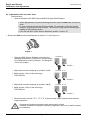
• Ensure that both eccentric bearings are in position "0“! (See Figure 1)
Figure 1
Position 0
536166T1.CDR
• Start the IMOS Service Software on the Service
Notebook and produce 2 test films of the test image
FLAT3002.bla by entering <Repair>, <Printengine>,
<Print Test Image>.
1
2
= Testfilm 1
Position -0.13
• Make another 2 films of the test image
FLAT3002.bla.
536166T2.CDR
• Adjust both eccentric bearings on position "-0.13“.
1
2
= Testfilm 2
Position +0.13
• Make another 2 films of the test image
FLAT3002.bla
536166T3.CDR
• Adjust both eccentric bearings on position "+0.13“.
1
2
= Testfilm 3
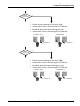
• Determine which test film (TF 1, TF 2, TF 3) has the least visible stripes and the darkest
image impression.
Homogeneity and highest density have equal priority criteria.
However, evaluation is always a subjective judgement, there are no defined values
for evaluation.
Chapter 6.6 / 4
Type 5361
Revision 26
Repair and Service
DD+DIS110.01E
Calibrations and adjustments
Testfilm 2
= best result
Y
536166TA.CDR
N
• Set both eccentric bearings on the value "-0.07".
• Make another 2 films of the test image FLAT3002.bla
• Afterwards adjust the eccentric bearings on "-0.2“
• Make another 2 films of the test image FLAT3002.bla
Position -0.2
1
2
536166T5.CDR
536166T4.CDR
Position -0.07
1
2
= Testfilm 5
= Testfilm 4
Testfilm 3
= best result
Y
536166TB.CDR
N
• Set both eccentric bearings on the value "+0.07".
• Make another 2 films of the test image FLAT3002.bla
1
2
536166T7.CDR
536166T6.CDR
• Afterwards adjust the eccentric bearings on "+0.2“
• Make another 2 films of the test image FLAT3002.bla
Position +0.07
Position +0.2
= Testfilm 6
Revision 26
Type 5361
1
2
= Testfilm 7
Chapter 6.6 / 5
Repair and Service
DD+DIS110.01E
Calibrations and adjustments
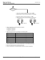
Testfilm 1
= best result
Y
536166TC.CDR
• Set both eccentric bearings on the value "+0.07".
• Make another 2 films of the test image FLAT3002.bla
1
2
536166T9.CDR
536166T8.CDR
• Afterwards adjust eccentric bearings on "-0.07“
• Make another 2 films of the test image FLAT3002.bla
Position +0,07
Position -0,07
1
= Testfilm 8
2
= Testfilm 9
• Always depending on the best position compare:
TF 4 and TF 5 with TF 2
TF 6 and TF 7 with TF 3
TF 8 and TF 9 with TF 1
• Adjust the eccentric drum according to the following table:
Best test film
TF 1
TF 2
TF 3
TF 4
TF 5
TF 6
TF 7
TF 8
TF 9
Adjustment value for the eccentric drum
0
- 0.13
+ 0.13
- 0.07
- 0.2
+ 0.07
+ 0.2
+ 0.07
- 0.07
• Note the adjustment value on the provided sticker on the thermal print head.
• Mount the right hand and left hand panels again.
• Now the modification is completed and the device is ready for operation.
Chapter 6.6 / 6
Type 5361
Revision 26
Repair and Service
DD+DIS110.01E
Calibrations and adjustments
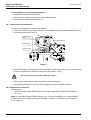
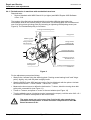
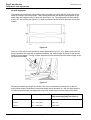
2.4 Adjustment of belt tension and belt tread of the main drive assembly
After replacement of the drum, drum motor, worn belts or any other part of the main drive
assembly it will be necessary to carry out the following adjustments:
Machine serial numbers
Adjustment
Description in chapter
5750, 5752, 5754 to 5761
•
Flat belt tension
•
2.4.3
≥ 5763
•
Flat belt running askew
•
2.4.4
< 5763 (except 5750, 5752,
5754 to 5761)
•
Toothed belt tension
•
2.4.1
•
Flat belt tension
•
2.4.2
•
Flat belt running askew
•
2.4.4
The slightest modification of one of the three adjustments mentioned
above will automatically influence the other two. As a consequence, it is
recommended to re-check continuously the three adjustments when
modifying one of them.
Drum motor
Drum
Flat belt
Stiffening plate
Bearing bush
Timing belt
Flat belt pulley
Timing belt pulley
Figure 2
Revision 26
Type 5361
Chapter 6.6 / 7
Repair and Service
DD+DIS110.01E
Calibrations and adjustments
Tools needed to carry out the adjustments:
• crosshead screwdriver Philips size 2,
• special tool for carrying out the drum torque measurement,
• torque spanner with screw head size 13.
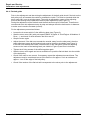
2.4.1 Belt tension of toothed belt
To carry out the adjustment, proceed as follows:
• loosen the 4 screws (see Figure 4) that fix the bearing bush to the stiffening plate as well as
the locking screw (see Figure 3),
Tread adjusting
screw
Bearing bush
Locking screw
Figure 3
• press down slightly the timing belt pulley (see figure 2) with one hand, do not press too hard
in order to avoid the belt tension of being too tight, approx. 1.3 kg,
Do not use a lever to press down the pulley.!
• with the other hand, tighten up the 4 screws of the bearing bush,
• screw tight the locking screw to the stiffening plate, but do not tighten too hard!
2.4.2 Belt tension of flat belt
Required tools:
• Service Notebook with IMOS Start 4.09 (or higher) and IMOS Drystar 3000 Software ≥
rev. 2.19.
Note: In case IMOS Drystar 3000 Software ≥ rev. 2.19 is not available (e.g. usage of IMOS
Drystar 2.05) or the machine has device software < release 1.40 installed, refer to section
2.4.2.1 page 10.
Chapter 6.6 / 8
Type 5361
Revision 26
Repair and Service
DD+DIS110.01E
Calibrations and adjustments
Figure 4
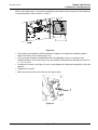
The flat belt tension can be adjusted by turning the reinforcement (stiffening plate) on which
the intermediate shaft of the flat belt pulley is mounted. The stiffening plate can be turned
around one of its fixing points (pivoting point) by loosening or tightening the adjusting screw
(see Figure 4). (The toothed belt pulley is not shown.)
To carry out the adjustment, proceed as follows:
• loosen slightly the 4 screws fixing the stiffening plate just enough to allow the plate to pivot
• Start IMOS Drystar 3000 and connect to the printer. Select REPAIR → PRINT ENGINE →
MODULES → DRUM.
• Perform a measurement of the torque of the drum motor to define the belt tension. To do
so, block the turning of the drum pulley with a screw driver (see Figure 7) press on TORQUE.
In the next window press on START (See Figure 6)
• Turn at the adjusting screw (clockwise corresponds to higher torque), until the value 2.40 ±
0.1 is reached. This value corresponds to the correct torque.
Revision 26
Type 5361
Chapter 6.6 / 9
Repair and Service
DD+DIS110.01E
Calibrations and adjustments
Figure 5
Figure 6
Figure 7
Note: Blocking the belt pulley by means of a screwdriver.
Avoid the motor to run for a longer period than 5 min. at such a low speed
since the temperature of several electronic components on the PMC-print
could become too high.
• Press cancel to leave the adjustment screen
• Tighten the 4 screws for fixing the stiffening plate
2.4.2.1 Adjustment with IMOS Drystar < 2.19 or device SW < rel. 1.40
• loosen slightly the 4 screws fixing the stiffening plate just enough to allow the plate to pivot
• Cut one of the wires of the drum motor and connect the wire again by putting a multimeter
in between so that the current can be measured.
• Start IMOS Drystar 3000 and connect to the printer. Select TOOLS → TERMINAL
• Perform a measurement of the current of the drum motor to define the belt tension. To do
so, start a terminal emulation session via IMOS à Tools à Terminal and type
mon res <Enter>
at message "AOS started" press <ENTER>
T14 <CR>
MS <CR> and wait until the message “Command terminated” is displayed. Then type
Chapter 6.6 / 10
Type 5361
Revision 26
Repair and Service
DD+DIS110.01E
Calibrations and adjustments
M1 <CR> (for activating the drum motor)
1 <CR> (for putting it on)
1 <CR> (for turning backwards)
500 (for a speed of 500µm/s)
DO NOT YET PUSH THE RETURN KEY.
• Block the drum pulley (see Figure 7) and press the RETURN key.
• Measure the current. It should be 2400 +/- 200 mA. If not in this range use the set screw of
the driving assembly to adapt the current value: Turning clockwise corresponds to a higher
current.
• Leave the T14 program (M1 <ENTER>; 0 <ENTER>, quit <ENTER>)
• Remove the multimeter.
• Solder the wire ends of the drum motor and isolate them with isolating tape
• Tighten the 4 screws for fixing the stiffening plate
.
Revision 26
Type 5361
Chapter 6.6 / 11
Repair and Service
DD+DIS110.01E
Calibrations and adjustments
2.4.3 Flat belt tension in machines with toothed belt tensioner
Required tools:
• Service Notebook with IMOS Start 4.09 (or higher) and IMOS Drystar 3000 Software
≥ Rev. 2.19.
The tension of the flat belt can be adjusted by turning the stiffening plate where the
intermediate shaft of the flat belt pulley is connected. The stiffening plate can turned around
one of its fixing points (pivoting point) by loosening or tightening the adjusting screw (see
Figure 8). The toothed belt pulley is not shown.
Locking screw bearing bush
Hinge point
Stiffening plate
Fixing screw for
flat belt pulley
Fixing screws
bearing bush
Left main side panel
Adjusting screw for
flat belt tension
Locking screw
bearing bush
Locking screw bearing bush
536166ba.cdr
Figure 8
For the adjustment proceed as follows:
• Slacken the 4 screws fixing the stiffening plate ("locking screw bearing bush" and "hinge
point") slightly, only until the plate is slightly loose.
• Start the IMOS Drystar 3000 and connect the Service Notebook with the printer. Activate
the functions REPAIR → PRINT ENGINE → MODULES → DRUM.
• Measure the drum torque to define the belt tension. To do so, block the turning drum belt
pulley with a screwdriver (see Figure 11)
•
Press on TORQUE, and press on START in the next window (see Figure 10)
• Turn the adjusting screw (clockwise turning increases the torque), until the value 2.40 ± 0.1
is obtained. This value corresponds to the correct value.
The motor must not run for more than 5 min in this slow speed since
otherwise the temperature of some electronic components on the PMC
Board increases to far.
Chapter 6.6 / 12
Type 5361
Revision 26
Repair and Service
DD+DIS110.01E
Calibrations and adjustments
Figure 9
Figure 10
Figure 11
Note: Block the belt pulley by means of a screwdriver.
• Press CANCEL to leave the adjustment screen.
• Tighten the 4 screws to fix the position of the stiffening plate.
Revision 26
Type 5361
Chapter 6.6 / 13
Repair and Service
DD+DIS110.01E
Calibrations and adjustments
2.4.4 Flat belt guide
Prior to the adjustment and also during the adjustment of the belt guide check if the belt on the
belt pulley runs off towards the outside or towards the inside. This mist be checked while the
drum motor (M1) runs at printing speed. The guide is adjusted by means of the adjusting
screw at the bearing bush inside the machine (track adjustment) (see Figure 3).
During the adjustment of the flat belt track the belt tension may be influenced. Therefore we
recommend to do this adjustment step by step and always check the belt tension in-between
to make sure it remains constant (correct).
For the adjustment proceed as follows:
• Loosen the 4 screws which fix the stiffening plate (see Figure 8).
• Start the drum motor (M1) with print speed (IMOS à Repair à Print Engine à Modules à
Drum …) and check in which direction the belt runs off.
• Stop the motor again.
• Adjust the track. If the belt runs towards the outside, away from the side panel, then the
track adjustment screw at the bearing bush must be turned to clockwise (see Figure 3).
If the belt runs towards the inside, in the direction of the side panel, place the adjusting
screw on the back of the bearing bush (not visible in Figure 8) and turn it clockwise.
• Tighten the 4 fixing screws of the stiffening plate again.
• Start the drum motor again and use a screwdriver to push the flat belt back into the middle
of the belt pulley.
• Check if the track is now correct. If necessary, repeat the adjustment several times. The
adjustment may be considered correct if the belt runs for approx. 5 min at a distance of
approx. 1 mm of the edge of the belt pulley.
• Check if the tension of the flat belt still corresponds to the value prior to the adjustment.
Chapter 6.6 / 14
Type 5361
Revision 26
Repair and Service
DD+DIS110.01E
Calibrations and adjustments
2.5 Horizontal and vertical film alignment
Horizontal alignment
To position a printed image horizontally on a sheet, the sheet has to be repositioned under the
TH until the correct position has been reached.
The printed image is made by the TH and the TH-position cannot be adjusted in the casting.
Figure 12
The displacement of the sheet under the TH can be done with the horizontal film alignment
assembly. This assembly is adjustable between the two side panels of the printer.
Revision 26
Type 5361
Chapter 6.6 / 15
Repair and Service
DD+DIS110.01E
Calibrations and adjustments
To perform a horizontal (and vertical) alignment, a test print is needed to visualize the
deviation. Before making this proof print, check the sheet feeder and put not more than 5
sheets in the feeder. Measure the margin of the printed image at the first printed rows.
Measure the left and right margin.
Calculate the difference between the measured results. Divide the result by two.
The remaining value gives the necessary displacement of the sheet to obtain a centered
image on the sheet. e.g.:
• Left margin = 6,2; right margin 2,4
• Difference 6,2 - 2,4 = 3,8
• Displacement 3,8 : 2 = 1,9
The sheet has to be displaced 1,9 mm to the right in order to center the image on the sheet.
Figure 13
The notch of the sheet is at the right lower side of the printer. In this example, the sheet has to
be displaced 1,9 mm to the right. This means that the alignment assembly has to be displaced
1,9 mm to the right.
Chapter 6.6 / 16
Type 5361
Revision 26
Repair and Service
DD+DIS110.01E
Calibrations and adjustments
Remove the side covers. To locate the adjusting screw and the securing point of the assembly
on the side panels, refer to Figure 14, item 1.
Figure 14
• First measure the distance (SGD) between the edge of the alignment assembly and the
edge of the fixture with a slide gauge. E.g.:
• In the previous example the assembly had to be displaced 1,9 mm to the right. If the
distance (SGD) is 2 mm (see Figure 15), the distance (SGD) after the adjustment has to be
2 - 1,9 = 0,1 mm.
• Loosen the 2 screws (see figure 8, item 1) and displace the alignment assembly to the right
position.
• Tighten the 2 screws.
• Make a proof print and control the left and right margin.
1
Figure 15
Revision 26
Type 5361
Chapter 6.6 / 17
Repair and Service
DD+DIS110.01E
Calibrations and adjustments
Vertical alignment
The adjustment mechanism which aligns the front edge of the print with the front edge of the
sheet is located in the sheet feeder. This mechanism allows the displacement/rotation of the
sheet edge with regard to the TH print line (see Figure 19). The adjustment can be made by
means of 2 set screws (see Figure 17), which are located at the left and right side of the load
system.
Figure 16
One turn of the set screw corresponds with a displacement of ± 0,7 mm. When turning the set
screw clockwise the sheet will be adjusted upwards, the white margin at the top of the printed
sheet becomes bigger. Turning counter clockwise lowers the sheet and the white margin at the
top becomes smaller.
Figure 17
Normally the white top margin should be 5 mm on a normal sheet, printed from an almost
empty sheet feeder. Because the real sheet length has a tolerance of ± 0,8 mm with regard to
the nominal sheet length, the adjustment has to be made from the lower edge of the sheet.
Format
Nominal length
Adjustment distance regarding to the
lower sheet edge [mm] (see figure 9)
14"x17"
17“ ≈ 429.7 mm
424.7 ±0.2
14"x14"
14“ ≈ 354.0 mm
349 ± 0.2
14"x11"
11“ ≈ 278.6 mm
273.6 ± 0.2
Chapter 6.6 / 18
Type 5361
Revision 26
Repair and Service
DD+DIS110.01E
Calibrations and adjustments
The white top margin increases with about ± 0.8 mm between a completely filled sheet feeder
and an almost empty feeder, the proof print has to be made with maximum 5 sheets in the
sheet feeder.
Measure the white top margin on the proof print, as well on the left as on the right side (See
Figure 16)
Calculate the difference between the measured results. E.g.
• Left side
426,6 - 424,7 = 1,9 mm
• Right side
424,5 - 424,7 = -0,2 mm
• The left side must raise over 1,9 mm, so turn the left set screw CW over ± 2,7 turns.
• The right side must lower over 0,2 mm, so turn the right set screw CCW over ± 0,3 turns.
• Make a proof print and check the top margin.
2.6 Changing the film size
• Open the film loading assembly.
• Remove the remaining film.
• Loosen the screw (2) on both sides of the film loading assembly as indicated on Figure 18.
Figure 18
• Slide both sides parallel and smoothly into the new position in order to keep the plastic
hooks (see Figure 19) horizontal. It is possible that the shaft between the stops falls down if
the assembly is not moved horizontally. In that case the cover has to be removed in order
to reinstall the shaft.
Revision 26
Type 5361
Chapter 6.6 / 19
Repair and Service
DD+DIS110.01E
Calibrations and adjustments
Figure 19
• Remove the three screws of the slide bar on the left and right side of the cover. (See 1 on
Figure 18)
• Take care that the film loading assembly doesn’t fall but bring it gently into horizontal
position. Don’t put any weight on the film loading assembly as it is only hold by the hinges.
• Remove the cable to sensor S4.
• Loosen the three screws that fix the 3 pins onto the pressure plate. The position of these
pins depends on the installed film size. (See Figure 21)
• Remove the pressure plate.
• Loosen the two Allen screws (2,5 mm) on each of the positioning brackets and put them in
the new position (Figure 20)
Figure 20
• Position the spring holders, pins and springs for the new film format on the pressure plate
according to Figure 21.
Chapter 6.6 / 20
Type 5361
Revision 26
Repair and Service
DD+DIS110.01E
Calibrations and adjustments
Figure 21
Revision 26
Type 5361
Chapter 6.6 / 21
Repair and Service
DD+DIS110.01E
Calibrations and adjustments
Remarks:
Þ The spring holder can be removed by pushing it from the rear to the front side. On the
rear side 3 clips should be pushed towards the center.
Þ For the 14x14” one small spring is not used and for the 14x11” one small and one large
spring are not used. Keep them in a safe place in case you need them again.
• Install the pressure plate to the rear plate by fixing the three screws in the pins
• Connect the cable sensor S4.
• Fix the sliding bars on each side with the three screws.
• Use the IMOS service software: Install à defaults and click “Client” and the appropriate film
format to install the correct parameters.
• Print a test film and check if the vertical alignment is correct and align it if necessary (See
Horizontal and vertical film alignment).
Chapter 6.6 / 22
Type 5361
Revision 26
Repair and Service
DD+DIS110.01E
Calibrations and adjustments
2.7 Thermal head pressure adjustment
Note: this adjustment has to be carried out after replacement or dismounting the
TH Cam assembly
Before carrying out the pressure adjustment the Drystar must be placed in its start-up
condition:
• acceptor film fed in,
• separation and outlining completed,
• thermal head in home position (completely backwards),
• pressure rollers on the drum in home position (completely backwards).
In order to have easy access to the components, the left and right cover and the rear panel
must be removed.
The following tools and accessories are needed to carry out the adjustment:
• crosshead screwdriver Philips size 2 (length approx. 200 mm),
• spanner size 10,
and the tool kit EB+53611750
• 2 x synthetic ring,
• 2 x bolt with wing nut,
• 2 x pin,
• 2 x steel cable,
• 2 x dynamometer 0 -10 kg,
• 2 x adapter with deep groove ball bearing,
• seal wax
When the machine is in start-up condition and the covers and panels are removed, start
assembling and installing the two measuring tools (one on each side of the machine). Proceed
as follows (see Figure 22):
• place the synthetic ring in the hole on top of the main side plate,
• insert the bolt in the ring and fix it with the wing nut, make sure that the bolt is screwed
down as far as possible,
• fix the dynamometer to the bolt,
• screw the pin into the threaded stud on the aluminum casting element which appears
through the opening in the main side plate,
From now on it is impossible to open the thermal head compartment.
• screw the adapter with the deep groove ball bearing into the threaded hole provided on the
main side plate approx. 4 cm from the threaded stud (to the rear),
• take the steel cable, attach it to the pin, guide it in the deep groove ball bearing and hook it
on the dynamometer,
Revision 26
Type 5361
Chapter 6.6 / 23
Repair and Service
DD+DIS110.01E
Calibrations and adjustments
• install the same measuring tool on the other side of the Drystar.
Bolt
Wing screw
Synthetic ring
Main side panel
Dynamometer
Adapter with deep
groove ball bearing
Steel cable
Pin
Sand casting element
Figure 22
The Drystar is now ready for adjustment, proceed as follows:
• put the thermal head in pre-print position, (refer to the IMOS - menu: Repair -> Printengine > Modules -> Printhead)
*In IMOS Drystar 3000 version 2.19 the motor can
not be controlled due to a software error
Cure:
1) Open a terminal window (IMOS à tools à
terminal).
2) As shown in Figure 24 enter the commands
"can", "m3" and "3". Then the motor drives into the
"preprint position".
Chapter 6.6 / 24
Type 5361
Figure 23
Revision 26
Repair and Service
DD+DIS110.01E
Calibrations and adjustments
• check that the thermal head touches the inserted film. Tap with your finger tops on the
aluminum casting element, to check that the aluminum casting element does not move. It is
possible to access the rear of the aluminum casting element when the rear panel of the
Drystar is removed,
• start turning both wing screws alternatively and clockwise so that the dynamometers pull
the thermal head away from the drum. Tap with your finger tops on the rear of the
aluminum casting element to determine the exact point where the thermal head detaches
from the drum. As soon as the thermal head detaches, the casting element will swing
slightly on its springs,
• read the thermal head pressure on the dynamometers. The optimum pressure is 5.3 kg on
each side ± 5%. It is important that both dynamometers read the same value,
adjust and equilibrate the pressure on both sides of the thermal head. Turn the M6 screws
provided under the hand grip at the rear with the cross head screwdriver, clockwise to
increase the pressure, and anti-clockwise to decrease the pressure.
Figure 24
Revision 26
Type 5361
Chapter 6.6 / 25
Repair and Service
DD+DIS110.01E
Calibrations and adjustments
• remove the measuring tools and secure the M6 adjusting screws. Tighten up the lock nut
M6 against the hinge plate and secure it with seal wax.
To avoid the adjusting nut from moving when tightening the lock nut, retain it with the cross
head screwdriver. To do this it is necessary to open first the hinged part of the thermal head
and put the thermal head back in pre-print position. (refer to the IMOS - menu: Repair ->
Printengine -> Modules -> Printhead)*
*In IMOS Drystar 3000 version 2.19 the motor can
not be controlled due to a software error
Cure:
1) Open a terminal window (IMOS à tools à
terminal).
2) As shown in Figure 24 enter the commands
"can", "m3" and "2". Then the motor drives into the
"home position".
Figure 25
Figure 26
Chapter 6.6 / 26
Type 5361
Revision 26
Repair and Service
DD+DIS103.02E
Calibrations and adjustments
3 Calibrations
The calibrations procedures in SW Rel. 1.7X and 1.9X differ in details. The two tables below list these differences. They also show, where to find detailed information to the calibration.
3.1 Overview of calibrations and related procedures SW Rel. 1.7X
PROCEDURE /
CALIBRATION
TH Profile
Film sensito
Maximum
density
Film to film
Registration
Reference film
Density Meter
DESCRIPTION
Correct the thermal head profile
Correct for the sensitometry of the film
Set the Dmax to default (=3.0)
Correct for density drift
Reduces mechanical mis-registration of the
MDM
Determines new reference values for the
MDM
Calibrate MDM sensitivity
AUTOMATIC
No
No
No
DEFAULT
CONFIRM START
BY OPERATOR
CONFIG BY
OPERATOR
CONFIG BY
SERVICE via NVE
DEFAULT
MANUAL START
BY OPERATOR
Yes
Yes
Yes
MANUAL START BY
SERVICE via IMOS
Yes
Yes
Yes
refer to
section
3.7
3.9
3.8
Yes
No
ON
No
No
ON/OFF (4)
Off
No
Yes
No
Yes
3.4
No
Yes
Yes
3.5
No
Yes
Yes
3.6
MANUAL START BY
SERVICE via IMOS
No
refer to
section
On
MANUAL START
BY OPERATOR
Yes
On
Yes
Yes
3.7
On
Yes
Yes
3.9
Off
No
No
3.2 Overview of calibrations and related procedures SW Rel. 1.9X
PROCEDURE /
CALIBRATION
Clean TH *
AUTOMATIC
Display
Warning
DEFAULT
1000 films
CONFIG BY
OPERATOR
No
Stop printing to allow cleaning of TH
TH profile
Correct the thermal head profile
Display
Warning
5000 films
No
Film sensito
Correct for the sensitometry of the film
Yes
New film pack
(100 films)
No
ON/OFF
Film to film
Correct for density drift
Yes
OFF
No
ON/OFF
Registration
Reduces mechanical mis-registration of the
MDM
Determines new reference values for the
MDM
Calibrate MDM sensitivity
No
No
Yes
3.4
No
No
Yes
3.5
No
No
Yes
3.6
Reference
MDM
DESCRIPTION
CONFIRM START
BY OPERATOR
CONFIG BY
SERVICE via NVE
ON/OFF/NUM
(1)
ON/OFF/NUM
(2)
ON/OFF
(3)
ON/OFF
(4)
DEFAULT
(1) DR3XXX11 parameter 'th_clean_print'. Period for automatic 'TH cleaning' message is expressed in a number of print-outs. Entering zero ('0') disables this message. Default 1000.
(2) DR3XXX11 parameter 'th_profile_prin': Period for automatic 'TH profile calibration' message is expressed in a number of print-outs. Entering zero ('0') disables this (semi-) automatic calibration. Default 5000.
(3) DR3XXX11 parameter 'sensito_mode'. Enables/Disables the automatic sensitometric calibration in case a new film package is inserted after 'empty magazine' message. Entering zero ('0') disables this automatic
calibration. Default 1 (enabled).
(4) DR3XXX11 parameter 'edge_scan': When set to '1', this enables the 'film to film calibration', when set to '0' disables the 'film to film calibration'. Default 1 for SW 1.7X and 0 for SW 1.9X
*When message 'need TH cleaning' appears on the local display after 1000 printed films the customer has to do the TH cleaning procedure via the local keypad (menu 5: calibration - 3: cleaning TH) as described
in reference user manual page 116. Just opening the TH door and clean the TH (without entering the 'clean TH' menu) will not reset the message.
Revision 32
Type 5361
Chapter 6.6 / 27
Repair and Service
DD+DIS103.02E
Calibrations and adjustments
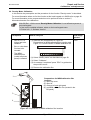
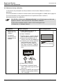
3.3 Overview of keypad and IMOS service software calibration menus in SW Rel. 1.7X and 1.9X
The three figures enclosed show where to find the calibrations on the local keypad and in IMOS Drystar 3000 (rev. ³ 2.19). The table enclosed explains the different calibration sub-menus.
?
?
ESC
ERROR
ESC
ERROR
5x
5x
ENTER
Status:
SW Rel. 1.7
?
ENTER
Status:
SW Rel. 1.9
ESC
ERROR
?
ESC
ERROR
ENTER
?
ENTER
?
ESC
ERROR
ESC
ERROR
ENTER
?
ENTER
?
ESC
ERROR
ESC
ERROR
ENTER
explanation see table 1
ENTER
explanation see table 1
536166AQ.CDR
Figure 27: Calibrations at local keypad with SW Rel. 1.7X
Select: REPAIR - PRINTENGINE - MODULES - MDM Calibrations
explanation see table 1
536166AX.CDR
Figure 28: Calibrations at local keypad with SW Rel. 1.9X
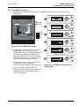
Menu
Description
1. Show calibration
·
Show the status of the current calibration:
"Last calibration okay" or
"Calibration disabled" or
"Default calibration" (= defaults used)
·
Date of last calibration
·
Number of passes since last calibration
2. Calibrate
·
Carry out the selected calibration.
3. Restore previous
·
Restore the previous calibration data of the selected calibration. A backup of
these data is always stored on the C: partition of the hard disk.
4. Restore defaults
·
Restore the default calibration data of the selected calibration. The default
calibration data are always stored on the C: partition of the hard disk.
5. Mode
·
Change the calibration mode (manual or automatic). Only available as of
SW Rel. 1.9X
6. Exit
·
Exit this menu
536166AR.CDR
Figure 29: Calibrations via IMOS Drystar 3000
Chapter 6.6 / 28
536166BQ.CDR
Table 1
Type 5361
Revision 32
Repair and Service
DD+DIS103.02E
Calibrations and adjustments
3.4 Registration Calibration
In this section the prerequisite, the procedure and the corresponding test image for the function
"registration calibration" is described.
For more information where to find the function at the local keypad or in IMOS refer to page 28.
For more information to the purpose and when to be performed refer to section 5,
Macrodensitometer film calibrations.
With SW Rel. 1.9X the menu 'Registration calibration' is not offered anymore at the
local keypad.
To find out the installed software, select on the local keypad menu
'4. Printer Info - 3. Software Version'.
Prerequisite
How to carry out
·
SW rel. 1.6 or
higher has to be
installed.
(1) Select "registration
calibration" as described
on page 28.
·
Blue or clear base
film has to be
inserted.
(2) Select "Calibrate".
Type 5361
536110AO.CDR
(3) Wait for approx. 3
minutes. Now the test film
(see beneath) is printed
and measured by the
MDM.
The calibration data are
automatically processed.
(4) At message "completed"
press "ESC" to get back to
the previous menu.
Revision 32
Test image printed
Chapter 6.6 / 29
Repair and Service
DD+DIS103.02E
Calibrations and adjustments
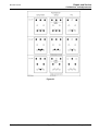
3.5 Reference Film Calibration
In this section the prerequisite and the procedure for the function "reference film" is described.
For more information where to find the function at the local keypad or in IMOS refer to page 28.
For more information to the purpose and when to be performed refer to section 5,
Macrodensitometer film calibrations.
With SW Rel. 1.9X the menu 'Reference film' is not offered anymore at the local
keypad.
To find out the installed software, select on the local keypad menu
'4. Printer Info - 3. Software Version'.
·
SW rel. 1.6. or
higher has to be
installed.
·
Blue or clear base
film has to be
inserted.
·
An external
densitometer for
measurement is
needed.
·
The MDM
calibration film
(inside left printer
panel) is needed.
How to carry out
Test image
printed
(1) Measure and note down the density of the 22
different squares on the MDM calibration film.
none
536110AK.CDR
Prerequisite
(2) Select "reference film" as described on page 28.
(3) Select "Calibrate".
(4) Select "Change density" (i.e. press ENTER at the
local keypad).
(5) With the arrow key alter the densities as just
measured. With the enter key go to next density.
ENTER
to go to next density s
to alter the densitie
536166AS.CDR
allowed limits for this step
(6) At message "completed" press "ESC" to get back to
the previous menu.
Chapter 6.6 / 30
Type 5361
Revision 32
Repair and Service
DD+DIS103.02E
Calibrations and adjustments
3.6 Density Meter Calibration
In this section the prerequisite and the procedure for the function "Density meter" is described.
For more information where to find the function at the local keypad or in IMOS refer to page 28.
For more information to the purpose and when to be performed refer to section 5,
Macrodensitometer film calibrations.
With SW Rel. 1.9X the menu 'Density Meter Calibration ' is not offered anymore at
the local keypad.
To find out the installed software, select on the local keypad menu
'4. Printer Info - 3. Software Version'.
How to carry out
·
SW rel. 1.6. or
higher has to be
installed.
·
Blue or clear base
film has to be
inserted.
·
The MDM
calibration film
(inside left printer
panel) is needed.
Test image
printed
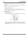
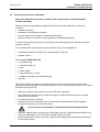
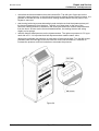
(1) Insert the film as described in Figure 30:
Preparations for MDM calibration film insertion and
Figure 31: Correct insertion of MDM calibration film
none
536110AK.CDR
Prerequisite
(2) Select "density meter" as described on page 28.
(3) Select "Calibrate".
(4) At message "completed" press "ESC" to get back to
the previous menu.
(5) Remove the calibration film.
1
Preparations for MDM calibration film
insertion
(1) open top cover
(2) open lid
(3) remove left and right panel
(4) get MDM calibration film (located in the
left panel)
2
3
4
536166AV.CDR
Figure 30: Preparations for MDM calibration film insertion
Revision 32
Type 5361
Chapter 6.6 / 31
Repair and Service
DD+DIS103.02E
Calibrations and adjustments
Correct insertion of MDM calibration film:
Sideview
FilmCarrier
Film
MDM Guide
okay
536110AK.CDR
not okay
536166au.cdr
Figure 31: Correct insertion of MDM calibration film
All covers have to be closed before the calibration is started.
Daylight influences the measurement.
Chapter 6.6 / 32
Type 5361
Revision 32
Repair and Service
DD+DIS103.02E
Calibrations and adjustments
3.7 TH profile calibration
In this section the prerequisite and the procedure for the function "TH profile" is described.
For more information where to find the function at the local keypad or in IMOS refer to page 28.
For more information to the purpose and when to be performed refer to section 5,
Macrodensitometer film calibrations.
It is recommended to clean the TH before this procedure. Refer to section 12,
maintenance instructions.
How to carry out
Test image printed
·
SW rel. 1.6. or
higher has to be
installed.
(1) Select "TH profile" as
described on page 28.
·
Blue or clear base
film has to be
inserted.
·
Registration
calibration has to
be performed
before (refer to
section 3.4, page
29).
(3) Wait for approx. 3
minutes. Now the test film
(see beneath) is printed
and measured by the
MDM. The calibration data
are automatically
processed.
(2) Select "Calibrate".
(4) Check the printed film for
dust artifacts at the bottom
side (lower 3 cm). In case
of dust artifacts the
measurement was wrong
and has to be repeated.
536110AI.CDR
Prerequisite
(5) At message "completed"
press "ESC" a few times
to get out of the user
menu.
(6) Print a flatfield: IMOS
Drystar 3000: "Repair ®
PrintEngine ® Print
Testpage ® flat001.bla
(7) In case the flatfield shows
acceptable uniformity the
calibration is finished.
Otherwise repeat the TH
profile calibration up to 2
times.
Revision 32
Type 5361
Chapter 6.6 / 33
Repair and Service
DD+DIS103.02E
Calibrations and adjustments
3.8 Maximum density calibration
In this section the prerequisite and the procedure for the function "Maximum density" is
described.
For more information to where to find the function at the local keypad or in IMOS refer to page 28.
For more information to the purpose and when to be performed refer to section 5,
Macrodensitometer film calibrations.
With SW Rel. 1.9X the menu 'Maximum Density' is not offered anymore at the local
keypad. In SW Rel. 1.9X it is part of the 'Film sensito' calibration.
To find out the installed software, select on the local keypad menu
'4. Printer Info - 3. Software Version'.
·
·
How to carry out
Test image printed
SW rel. 1.6. or
higher has to be
installed.
(1) Select "Maximum density" as
described on page 28.
An external
densitometer for
measurement is
needed.
(3) Wait for approx. 1 minute. Now the
test film (see beneath) is printed.
(4) Measure the densities of the 9
squares, and enter the lowest one.
(5) In case the max. density variations
of the test film are > 0.2 O.D.,
perform a TH profile calibration
first. Refer to section 3.7 page 33.
Otherwise proceed as described
here.
(2) Select "Calibrate".
Densities, to be measured
536110AF.CDR
Prerequisite
(6) Select Enter to confirm
(7) At message "completed" press
"ESC" a few times to get out of the
user menu.
(8) Now print a SMPTE test image and
check the image quality. Refer to
3.8.1 next page.
Chapter 6.6 / 34
Type 5361
Revision 32
Repair and Service
DD+DIS103.02E
Calibrations and adjustments
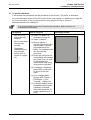
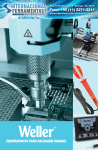
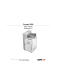
3.8.1 Print SMPTE Testimage
· After Maximum Density Calibration print an SMPTE test image for to check the printer
calibrations:
?
1
ESC
ERROR
ENTER
3x
Dmax
Dmin
?
2
ESC
ERROR
ENTER
95%
100% 3
0%
5%
4
?
ESC
ERROR
ENTER
?
ESC
ERROR
ENTER
1x
536166AY.CDR
Figure 32: Check SMPTE test image
?
·
Check Dmax. It has to be 3.0 ± 0.2 O.D. If
outside limits, print 4 more films, and
measure the 5th again. At huge deviations up
to 5 films are necessary to adapt the TH
power for Dmax of 3.0 O.D. If still outside
limits refer to section 6.3, Troubleshooting,
symptom "Dmax too high or too low".
ESC
ERROR
5
ENTER
wait ca. 2 minutes
3x
?
6
ERROR
ESC
ENTER
·
·
Check Dmin: It has to be 0.2 ± 0.07 O.D. If
outside limits refer to section 6.3
Troubleshooting, symptom "Dmin too high".
Check fields 5/0% and 95/100%. The
difference must be visible. If not, a sensito
calibration has to be performed. Refer to
section 3.9 page 36.
Revision 32
536110AB.CDR
Figure 33: Print SMPTE testimage at the
local keypad.
Type 5361
Chapter 6.6 / 35
Repair and Service
DD+DIS103.02E
Calibrations and adjustments
3.9 Film Sensito Calibration
In this section the prerequisite and the procedure for the function "Film sensito" is described.
For more information to where to find the function at the local keypad or in IMOS refer to page 28.
For more information to the purpose and when to be performed refer to section 5,
Macrodensitometer film calibrations.
With SW Rel. 1.9X the function 'Film Sensito Calibration' includes the Dmax
calibration.
To find out the installed software, select on the local keypad menu
'4. Printer Info - 3. Software Version'.
Prerequisite
How to carry out
Testimage printed
SW rel. 1.6. or
higher has to be
installed.
(1) Select "Film Sensito" as
described on page 28.
·
Blue or clear base
film has to be
inserted.
·
Dmax has to be in
the range of 3.0 ±
0.2 O.D.
(3) Wait for approx. 3 minute.
Now the test film (see
beneath) is printed and
automatically measured.
(2) Select "Calibrate".
(4) At message "completed"
press "ESC" to get back to
the previous menu.
536110AE.CDR
·
Note for sensito calibration with SW Rel. 1.9X:
In case the reached Dmax level after a film sensito calibration is below the target Dmax
(target Dmax = 3.10), a warning message is displayed 'Dmax= X.YZ'.
In this case a new film sensito calibration is recommended. In case the target Dmax cannot be
reached, printing can continue nevertheless.
Chapter 6.6 / 36
Type 5361
Revision 32