1
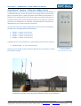
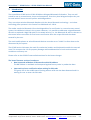
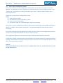
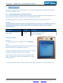
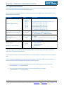
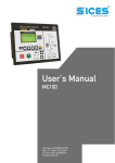
AccessZone ® - GC400 Series – GC401-GC404 User Manual
GC400 Series – GC401-GC404 User Manual
The New Generation of Wireless
Access Control Systems
User Manual for GC401-GC404 with firmware Ver. 0.49 and above, HW revision 03
For modules with serial numbers from 0011009
All information is subject to change without notice. All other products and brand names are registered trademarks of their respective companies
2010-07-06 US 1.03
Copyright © 2005-2010 All rights reserved MVC-Data ApS Skalhuse 5 9240 Nibe Denmark Web www.mvc-data.com E-mail [email protected] Phone +45 25 12 84 02
1/34
AccessZone ® - GC400 Series – GC401-GC404 User Manual
AccessZone® System - A Key to a Safer Future
Congratulations on choosing an AccessZone® GC400 Bluetooth Reader. It
is a flexible and easy to use system for controlling access to doors and
gates to private homes, shops and small and middle size companies. It
enables quick configuration with a few simple commands entered on a
standard mobile phone with Bluetooth without installing any software.
No license or subscription is required. The Bluetooth ID is send on the
Wiegand bus to an external access controller.
This manual covers the easy configuration and use of the AccessZone®
GC400 series of Wiegand Bluetooth Readers:
GC401 – 2 admin. and 5 users
GC402 – 2 admin. and 10 users
GC403 – 2 admin. and 20 users
GC404 – 2 admin. and 50 users
A GC500 series is also available as a stand-alone access control systems:
GC501-GC504 – 5, 10, 20 and 50 users
Please see the GC400 series Installation Manual for instructions on how
to install the system.
AccessZone® GC400 with
3 inputs/2 outputs
Form factor 127 x 47 x 8 mm
Get easy and seamless accesses to the secured areas with your mobile phone
working as a secure access key from a distance of 0.1 up to 10 meters.
All information is subject to change without notice. All other products and brand names are registered trademarks of their respective companies
2010-07-06 US 1.03
Copyright © 2005-2010 All rights reserved MVC-Data ApS Skalhuse 5 9240 Nibe Denmark Web www.mvc-data.com E-mail [email protected] Phone +45 25 12 84 02
2/34
AccessZone ® - GC400 Series – GC401-GC404 User Manual
Table of Contents
1 Disclaimer .........................................................................................................................................5
2 Introduction.......................................................................................................................................6
3 Security Precautions..........................................................................................................................7
4 System Overview...............................................................................................................................8
5 I/O Description..................................................................................................................................8
5.1 Inputs..........................................................................................................................................8
5.2 Outputs.......................................................................................................................................8
6 LED Status..........................................................................................................................................9
6.1 Power Up....................................................................................................................................9
6.2 Blue LED......................................................................................................................................9
6.3 Green LED / Ext. Red LED...........................................................................................................9
6.4 Red LED / Ext. Green LED...........................................................................................................9
7 How to Configure the System..........................................................................................................10
7.1 Commands via Mobile..............................................................................................................10
7.2 How to enter Configuration Mode...........................................................................................11
7.3 How to enter System Commands – Configuration Mode........................................................12
7.3.1 If the system doesn’t respond to a command:.................................................................12
7.4 How to Add or Delete Users – Normal Operation...................................................................13
7.4.1 If the system doesn’t respond to a command:.................................................................13
8 System Commands..........................................................................................................................14
8.1 Change 8 digit Master PIN Code Command.............................................................................14
8.2 Add new User Command.........................................................................................................15
8.3 Delete User Command.............................................................................................................17
8.4 Change System Configuration Command 1.............................................................................18
8.5 Change System Configuration Command 2 – Advanced settings............................................19
9 Wiegand Types................................................................................................................................21
9.1 Wiegand 26...............................................................................................................................21
9.2 Double Wiegand 26..................................................................................................................22
9.3 Triple Wiegand 26....................................................................................................................22
9.4 Wiegand 34...............................................................................................................................22
9.5 Wiegand 42...............................................................................................................................23
9.6 Wiegand 50...............................................................................................................................23
9.7 Wiegand 58...............................................................................................................................23
9.8 Wiegand 40 with XOR checksum..............................................................................................23
9.9 Wiegand 56 with XOR checksum..............................................................................................24
9.10 Wiegand 64 with XOR checksum............................................................................................24
10 Virtual Keypad...............................................................................................................................25
10.1 Virtual Keypad only Mode......................................................................................................25
10.2 Virtual Keypad Mixed Mode...................................................................................................25
11 User Access Key Setup...................................................................................................................26
11.1 Mobile Phone as Key..............................................................................................................26
11.2 GPS Key as Key........................................................................................................................27
11.3 AccessZone Bluetooth Tags....................................................................................................27
12 Access Detection Range................................................................................................................28
12.1 Detection Range Command Examples...................................................................................28
12.2 Detection range is to short.....................................................................................................29
12.3 Detection range is too long....................................................................................................29
13 Default Factory System Settings....................................................................................................30
All information is subject to change without notice. All other products and brand names are registered trademarks of their respective companies
2010-07-06 US 1.03
Copyright © 2005-2010 All rights reserved MVC-Data ApS Skalhuse 5 9240 Nibe Denmark Web www.mvc-data.com E-mail [email protected] Phone +45 25 12 84 02
3/34
AccessZone ® - GC400 Series – GC401-GC404 User Manual
13.1 Restore Factory Default System Settings...............................................................................30
14 Appendix A – User Log Template..................................................................................................31
15 Appendix B – System Master PIN Code Log Template..................................................................31
16 Appendix C – System Configuration Log Template.......................................................................31
17 Appendix B – Quick Guide:............................................................................................................32
17.1 Mobile Phone used for Adding and Deleting Users – Normal Operation:.............................32
17.2 Mobile Phone used for System Commands - System Configuration Mode:..........................33
17.3 Mobile Phone as Access Key: ................................................................................................34
All information is subject to change without notice. All other products and brand names are registered trademarks of their respective companies
2010-07-06 US 1.03
Copyright © 2005-2010 All rights reserved MVC-Data ApS Skalhuse 5 9240 Nibe Denmark Web www.mvc-data.com E-mail [email protected] Phone +45 25 12 84 02
4/34
AccessZone ® - GC400 Series – GC401-GC404 User Manual
1
Disclaimer
All rights reserved.
MVC-Data ApS assumes no responsibility for any errors in this manual.
MVC-Data ApS is constantly working to improve its products and offer new features in
collaboration with customers and partners. Therefore, MVC-Data ApS reserves the right to change
the hardware, software and / or specifications without notice and shall have no obligation to
update the information contained in this manual.
MVC-Data ApS's products are not authorized for use as system-critical components in life
supporting devices or systems.
AccessZone® is a registered trademark of MVC-Data ApS. The Bluetooth trademark is owned by
the Bluetooth SIG. All other trademarks are owned by their respective owners.
The displayed screens may differ and depends on the mobile phone used for configuration.
Copyright © 2005-2010 MVC-Data ApS
All information is subject to change without notice. All other products and brand names are registered trademarks of their respective companies
2010-07-06 US 1.03
Copyright © 2005-2010 All rights reserved MVC-Data ApS Skalhuse 5 9240 Nibe Denmark Web www.mvc-data.com E-mail [email protected] Phone +45 25 12 84 02
5/34
AccessZone ® - GC400 Series – GC401-GC404 User Manual
2
Introduction
The AccessZone GC400 series GC401-GC404 are Wiegand Bluetooth ID Readers. They are well
suited for use in private homes, shops and companies. Since they have Wiegand output they can
be used with all access control systems with Wiegand bus.
They are unique wireless Bluetooth Readers with the latest Bluetooth technology – a wireless
technology that operates in the license free ISM band at 2.4 GHz.
The reader sends the Bluetooth ID on the Wiegand bus for verification in a central access control
system. No validation is done in the system. However, it is possible to add some unique Bluetooth
IDs with an optional 4 digit PIN code for increased security. I.e. the Bluetooth ID will first be sent to
the central access controller for final access verification after the unique PIN code has been
entered by the user.
The used mobile phones or other Bluetooth devices must be set to “visible” to allow them to be
discovered by the system.
The GC400 series eliminates the need for mechanical readers and keyboards outside the secured
area. This removes the risk for property damage and breakdown due to harsh environmental
conditions and heavy use.
Please refer to the GC400 Firmware Release Note for the latest changes.
The latest firmware versions introduces:
New improved validation of Bluetooth module BD address
The BD address is read back and compared against factory value in production data
Improved end-user notification when waiting for PIN code
The green LED in the middle starts flashing when a valid user has been detected and it is
waiting for user to enter the PIN code
All information is subject to change without notice. All other products and brand names are registered trademarks of their respective companies
2010-07-06 US 1.03
Copyright © 2005-2010 All rights reserved MVC-Data ApS Skalhuse 5 9240 Nibe Denmark Web www.mvc-data.com E-mail [email protected] Phone +45 25 12 84 02
6/34
AccessZone ® - GC400 Series – GC401-GC404 User Manual
3
Security Precautions
Several security precautions have been implemented in the system to make it safe to use.
The system will only accept system configuration commands in a special configuration mode (refer
to section 7.2 How to enter Configuration Mode).
All system configuration commands are entered by temporarily changing the mobile phones
friendly name1) and must be followed by a unique 8 digit Master PIN code. The Master PIN code
should only be known to a limited number of people (system administrators).
The 8 digit Master PIN code should be changed and is unique for each GC401-GC404 system. It can
be entered from any Bluetooth enabled mobile phone. Please change the Master PIN code before
continuing.
Two privileged users (administrators) can add and delete users at any time. Refer to section 7.4
How to Add or Delete Users – Normal Operation.
1)
Caution!
The Bluetooth friendly name feature is used for commands and can be read from another
Bluetooth device from the distance (typically up to 10 meters).
Therefore it is highly recommended to immediately change the Bluetooth friendly name again or
make the mobile phone invisibly to avoid that unauthorized people read the commands
containing vital user information.
All information is subject to change without notice. All other products and brand names are registered trademarks of their respective companies
2010-07-06 US 1.03
Copyright © 2005-2010 All rights reserved MVC-Data ApS Skalhuse 5 9240 Nibe Denmark Web www.mvc-data.com E-mail [email protected] Phone +45 25 12 84 02
7/34
AccessZone ® - GC400 Series – GC401-GC404 User Manual
4
System Overview
This section presents a system overview with an I/O description:
Input 2 (IN2)
External Buzzer
Output 1 (OC1)
Wiegand Data0 (D0)
Input 3 (IN3)
External Red LED
Output 2 (OC2)
Wiegand Data1 (D1)
Input 4 (IN4)
External Green LED
5
I/O Description
GC400 series have 3 inputs and 2 outputs.
The active levels (high ‘1’/low ‘0’), when an action is performed, can be configured (inverted) for
some inputs/outputs. Please refer to section 8.5 Change System Configuration Command 2 –
Advanced settings for more details.
5.1
Inputs
Input 1 (IN1) - Not used
Input 2 (IN2) - External control of buzzer / entering configuration mode during power up
Input 3 (IN3) - External control of Red (dual) LED
Input 4 (IN4) - External control of Green (dual) LED
5.2 Outputs
Open collector type (500mA):
Output 1 (OC1) - Wiegand Data0 (D0) output for external access controller
Output 2 (OC2) – Wiegand Data1 (D1) output for external access controller
Please see the GC400 series Installation Manual for instructions on how to install the system.
All information is subject to change without notice. All other products and brand names are registered trademarks of their respective companies
2010-07-06 US 1.03
Copyright © 2005-2010 All rights reserved MVC-Data ApS Skalhuse 5 9240 Nibe Denmark Web www.mvc-data.com E-mail [email protected] Phone +45 25 12 84 02
8/34
AccessZone ® - GC400 Series – GC401-GC404 User Manual
6
LED Status
The GC400 series have 3 internally controlled LEDs (Blue, Green
and Red) and two externally controlled LEDs (Red and Green) for
system indications.
The Green LED (mid) is a dual LED with an additional Red
LED controlled though input 3 (Orange core)
The Red LED (right) is a dual LED with an additional Green
LED controlled though input 4 (Blue core)
Dual LEDs
6.1 Power Up
The Blue LED and Red LED will light for 2 seconds from power up. This is the bootloader waiting for
new firmware. Will call the application if new firmware is not received.
6.2 Blue LED
Normal Mode - the Blue LED is solid on. It flashes shortly when any Bluetooth device ID is read
from a nearby Bluetooth device (e.g. a mobile phone).
Configuration Mode - the Blue LED blinks 1 time/sec. The device can accept commands
6.3 Green LED / Ext. Red LED
The Green LED starts blinking when waiting for user to enter the PIN code.
The Green LED flashes shortly when an Bluetooth ID has been read and is send on the Wiegand
bus.
The external Red LED is by default OFF (leave not connected). It can be controlled from an external
controller through input 3 (Orange Core). The LED is set ON by pulling input 3 down to GND.
6.4 Red LED / Ext. Green LED
The Red LED flashes shortly when an Bluetooth ID has been read but it could not be send on the
Wiegand bus because it was busy (to avoid collisions).
The external Green LED is by default OFF (leave not connected). It can be controlled from an
external controller through input 4 (Blue Core). The LED can be set ON by pulling input 4 down to
GND.
All information is subject to change without notice. All other products and brand names are registered trademarks of their respective companies
2010-07-06 US 1.03
Copyright © 2005-2010 All rights reserved MVC-Data ApS Skalhuse 5 9240 Nibe Denmark Web www.mvc-data.com E-mail [email protected] Phone +45 25 12 84 02
9/34
AccessZone ® - GC400 Series – GC401-GC404 User Manual
7
How to Configure the System
This section describes how to enter system commands and how to enable the system for
configuration. Section 8 System Commands describes the different commands in details.
7.1 Commands via Mobile
System configuration (adding/deleting users and changing system settings) can be done from any
Bluetooth enabled mobile phone.
Note!
It is not necessary to install any software on the mobile phone or use any PC tool.
The mobile phone used must support at least 20 characters as “Friendly Name” (also called
"Phone Name”). This is the name revealed for other Bluetooth devices.
A system command (e.g. "01,0022b4b62918,1234") is entered by temporarily changing the
mobiles Bluetooth “Friendly Name”. Refer to section 8 System Commands.
Please refer to the User Manual for a specific mobile phone type for how to change the Bluetooth
friendly name.
Caution!
The Bluetooth specification states a maximum length of 248 characters as Friendly Name.
However, most mobile phones have limited the space allowed for Friendly Name. A minimum of
20 characters must be supported by the used mobile phone.
All commands must be followed by an 8 digit Master PIN code for safe use. The system gives 3
short beeps to indicate that a valid command has been found and the Master PIN code is required.
The user will automatically be prompted when to enter the Master PIN code.
Note!
This is not the normal 4 digit user access PIN code.
Please note when entering the commands:
All command parameters (enclosed by <>) must be separated by a comma ','
No spaces between values are allowed
Have the exact length as specified. I.e. no additional characters in the end
A ‘-‘ indicates an integer range 1,2,3…
All information is subject to change without notice. All other products and brand names are registered trademarks of their respective companies
2010-07-06 US 1.03
Copyright © 2005-2010 All rights reserved MVC-Data ApS Skalhuse 5 9240 Nibe Denmark Web www.mvc-data.com E-mail [email protected] Phone +45 25 12 84 02
10/34
AccessZone ® - GC400 Series – GC401-GC404 User Manual
7.2 How to enter Configuration Mode
The system must be set into configuration mode before it will accept the system commands.
However, it is possible for two privileged users (administrators) to use the “Add new User” and
“Delete User” commands in normal mode (Refer to section 7.4 How to Add or Delete Users –
Normal Operation).
Follow these steps to enter configuration mode:
Steps:
1) Power off the module
2) Pull down the buzzer input (IN2) to GND
3) Power on the module again
4) The buzzer input can be released again after the short beep
The system is now in configuration mode for 10 minutes and will flash with the Blue LED. Refer to
section 7.3 How to enter System Commands – Configuration Mode for how to enter system
commands.
The system coverage range will be limited to approximately 20 cm in the configuration period to
prevent that unauthorized people can tamper with the system.
The configuration period is restarted every time a valid command has been executed.
Configuration mode is automatically terminated after 10 minutes without any valid commands by
sending 2 short beeps or by power cycling the device to startup in normal operation (Buzzer input
(IN2) is not pulled down to GND).
Caution!
The system will not scan for (detect) users in configuration mode. I.e. no Bluetooth IDs are send
on the Wiegand bus
All information is subject to change without notice. All other products and brand names are registered trademarks of their respective companies
2010-07-06 US 1.03
Copyright © 2005-2010 All rights reserved MVC-Data ApS Skalhuse 5 9240 Nibe Denmark Web www.mvc-data.com E-mail [email protected] Phone +45 25 12 84 02
11/34
AccessZone ® - GC400 Series – GC401-GC404 User Manual
7.3 How to enter System Commands – Configuration Mode
The system commands (adding/deleting users and changing system settings) can be executed
from any Bluetooth enabled mobile phone by temporarily changing the mobile phones friendly
name.
After entering a command and the Master PIN code the system gives a short beep to indicate that
the command has been accepted and executed and restarts the 10 minute configuration period.
The next command can be entered, or wait for the termination of the configuration period or
power cycle the device to startup in normal operation.
Note!
3 short beeps indicate when to use the Master PIN code instead of normal access PIN code.
Follow these steps to execute commands:
Steps:
1) Set system into configuration mode. Refer to section 7.2 How to enter Configuration Mode
2) Enable Bluetooth on mobile phone and set it to hidden
3) Enter the required system command on the mobile phone and click save. Refer to section8
System Commands for available commands
4) Set the mobile phone to visible
5) Place mobile phone within the detection range of the system
6) Wait for 3 short beeps
7) Enter Master PIN code (e.g. 12345678) when prompt
8) Wait for beep for successful execution of the command
9) Set the mobile phone to invisible/hidden
10) Erase command from mobile phone
If more commands must be executed repeat step 2) – 9)
7.3.1 If the system doesn’t respond to a command:
System is not in configuration mode any more (10 minutes time out)
- Check Blue LED - flashing? Else re-enter configuration mode. Refer to section 7.2 How to
enter Configuration Mode
The administrator is outside the allowed configuration range
- Administrator must get closer to the system
The command has already been executed
- Try change one of the parameters or try another command
The command is not valid
- Wrong number of parameters, wrong parameter values and/or wrong command length
(e.g. spaces at the end)
The system times out waiting to read the command or connection to mobile failed
- Wait for next detection
All information is subject to change without notice. All other products and brand names are registered trademarks of their respective companies
2010-07-06 US 1.03
Copyright © 2005-2010 All rights reserved MVC-Data ApS Skalhuse 5 9240 Nibe Denmark Web www.mvc-data.com E-mail [email protected] Phone +45 25 12 84 02
12/34
AccessZone ® - GC400 Series – GC401-GC404 User Manual
7.4 How to Add or Delete Users – Normal Operation
Privileged users (administrators) are stored on storage position 01 or 02. These two privileged
users (administrators) are allowed to add and delete users from normal operation mode. I.e. it is
not necessary to enter configuration mode first.
The user (administrator) must first enter the normal access 4 digit PIN code (access PIN code is
required) and then the 8 digit Master PIN code if a valid and new “Add new User” or “Delete User”
command has been found.
A short beep indicates that the command has been successfully executed as in normal
configuration mode.
TIP!
Make sure that the mobile phone used is stored on position 01 or 02 and have an access PIN code
before continuing. It will not accept commands in this mode if PIN code is not used.
Follow these steps to add or delete a user:
Steps:
1) Enter the required Add new User or Delete User command on the mobile phone and click
save (refer to section 8.2 Add new User Command and 8.3 Delete User Command)
2) Set the mobile phone to visible
3) Place mobile phone within the detection range of the system
4) Enter normal access PIN (e.g. 1234) when prompt – ID is sent on Wiegand bus if correct
5) Wait for 3 short beeps
6) Enter Master PIN code (e.g. 12345678) when prompt
7) Wait for beep for successful execution of the Add new User or Delete User command
8) Set the mobile phone to invisible/hidden
9) Erase command from mobile phone
If more users must be added/deleted repeat step 1) – 8)
7.4.1 If the system doesn’t respond to a command:
The administrator is outside the normal access range
- Administrator must get closer to the system
The command has already been executed
- Try change one of the parameters or try another command
The command is not valid
- Wrong number of parameters, wrong parameter values and/or wrong command length
(e.g. spaces at the end)
The system times out waiting to read the command or connection to mobile failed
- Wait for next detection
All information is subject to change without notice. All other products and brand names are registered trademarks of their respective companies
2010-07-06 US 1.03
Copyright © 2005-2010 All rights reserved MVC-Data ApS Skalhuse 5 9240 Nibe Denmark Web www.mvc-data.com E-mail [email protected] Phone +45 25 12 84 02
13/34
AccessZone ® - GC400 Series – GC401-GC404 User Manual
8
System Commands
This section describes the simple and easy to use mobile configuration command set for GC401 GC404- the Wiegand series.
8.1 Change 8 digit Master PIN Code Command
This command changes the Master PIN code which is used to validate all system commands. The
system will automatically prompt the user for the Master PIN code.
The Master PIN code is a system code for authenticating the user/system administrator.
Caution!
The default Master PIN code should be changed before use of the system. The Master PIN code
should only be known by a system administrator or a limited number of people to avoid
unauthorized use.
Parameters
Values
<New Master PIN code for
the system>
8 digits
Description
The Master PIN code for adding/removing users
and change system settings 1)
Default: “12345678”
Total length = 8 digits
Example:
To change Master PIN to 12345678 enter: "12345678"
Note!
The present (old) Master PIN code must be entered on the
mobile to enable the new Master PIN code.
The Master PIN code can be reset to factory value. Please
see section 13 Default Factory System Settings
System administrator should store the new master PIN
code in a system log. Please see 15 Appendix B – System
Master PIN Code
1)
The Master PIN code must be entered within 15 seconds before it continues to scan for another user.
All information is subject to change without notice. All other products and brand names are registered trademarks of their respective companies
2010-07-06 US 1.03
Copyright © 2005-2010 All rights reserved MVC-Data ApS Skalhuse 5 9240 Nibe Denmark Web www.mvc-data.com E-mail [email protected] Phone +45 25 12 84 02
14/34
AccessZone ® - GC400 Series – GC401-GC404 User Manual
8.2 Add new User Command
This command adds a new user to the system. This is also used for editing an exiting user. Make
sure to store the user on the same storage position.
This command can also be execute in normal mode by the privileged users (administrators) on
storage position 01 and 02.
Parameters
Values
<Add storage position>,
2 digits
01-02
03-07
03-12
03-22
03-52
<BD address of new device>,
12 digits
<PIN code for user>
4 digits
<power class>
(optional – not required)
1 digit
1-3
Description
Position in system database to store the user
Privileged users (administrators): “01”-“02” 1)
Normal users GC401: “03”-“07”
Normal users GC402: “03”-“12”
Normal users GC403: “03”-“22”
Normal users GC404: “03”-“52”
E.g. position 1 is written as “01”
The unique Bluetooth address of device
Valid values ‘0’-‘9’ and ‘A’-‘F’ or ‘a’-‘f’
E.g. “001256ABCDEF”, “00BB592F030B”
User access PIN code 2)
E.g. “1234”
Use “0000” to disables use of access PIN code
for that particular user
Device power class 3)
'1' = strong device
'2' = standard device
'3' = weak device.
Default: ‘2’
1)
The privileged users (administrators) must be added with a PIN code to be able to add other
users. This is a security requirement.
2)
The access PIN code must be entered within 15 seconds before it continues to scan for another
user.
3)
Can be used to compensate (normalize), in some degree, for power differences and antenna
location between the used Bluetooth keys (e.g. mobile phones):
If a device must be closer to the reader than most others before access is granted
- set parameter = '3' (weak device)
If a device gets access further away from the reader than most others
- set parameter = '1' (strong device)
All information is subject to change without notice. All other products and brand names are registered trademarks of their respective companies
2010-07-06 US 1.03
Copyright © 2005-2010 All rights reserved MVC-Data ApS Skalhuse 5 9240 Nibe Denmark Web www.mvc-data.com E-mail [email protected] Phone +45 25 12 84 02
15/34
AccessZone ® - GC400 Series – GC401-GC404 User Manual
Total length = 20 digits or optional 22 digits
Examples:
Examples:
On position 1 - add unique user 0022b4b62918 with PIN
code 1234 enter: "01,0022b4b62918,1234"
On position 5 - add unique user 0022b4b62918 without PIN
code enter: "05,0022b4b62918,0000"
On position 1 - add unique user 0022b4b62918 without PIN
code and strong enter: "01,0022b4b62918,0000,1"
On position 5 - add unique user 0022b4b62918 without PIN
code and weak enter: "05,0022b4b62918,0000,3"
Note!
Any exiting user on the storage position selected will be
erased. I.e. it is not necessary to erase an existing user first.
System administrator should maintain a system log of users
and storage positions used. Please see 14 Appendix A –
User Log Template
Caution!
A virtual “any” user is by default (factory) added at storage position 01 (a
privileged user) to allow an easy – first time - configuration of users without going
through the normal system configuration mode. PIN code 1234 is used.
This corresponds to the command: "01,FFFFFFFFFFFF,1234"
Bluetooth ID reader with unique users with PIN code:
It is highly recommended to overwrite this with a specific user with a unique PIN
code and move the “any” default user to the last location used. In example, move
“any” user to the last storage position 7 (GC401):
Execute command:."07,FFFFFFFFFFFF,0000"
The privileged users (devices) added on position 01 or 02 can be used to add other
users and the “any” user on position 07 will allow the system to send all other
Bluetooth IDs on the Wiegand bus.
Simple Bluetooth ID reader:
Add the “any” user without PIN code on storage position 01 if PIN code and no
privileged users (01 and 02) are not required. The Bluetooth reader will now send all
the detected Bluetooth IDs on the Wiegand bus:
Execute command:."01,FFFFFFFFFFFF,0000"
Refer to section 10 Virtual Keypad for more details
All information is subject to change without notice. All other products and brand names are registered trademarks of their respective companies
2010-07-06 US 1.03
Copyright © 2005-2010 All rights reserved MVC-Data ApS Skalhuse 5 9240 Nibe Denmark Web www.mvc-data.com E-mail [email protected] Phone +45 25 12 84 02
16/34
AccessZone ® - GC400 Series – GC401-GC404 User Manual
8.3 Delete User Command
This command deletes a user from the system.
This command can also be execute in normal mode by the privileged users (administrators) on
storage position 01 and 02.
Parameters
Values
<Delete storage position>
2 digits
01-02
03-07
03-12
03-22
03-52
Description
User position to delete from system database
Privileged users (administrators): “01”-“02”
Normal users GC401: “03”-“07”
Normal users GC402: “03”-“12”
Normal users GC403: “03”-“22”
Normal users GC404: “03”-“52”
Ex. position 1 = “01”, 8 = “08” and 10=”10”
Total length = 2 digits
Examples:
Delete privileged user (administrator) stored on position 1
enter: "01"
Delete normal user stored on position 5 enter: "05"
Note!
An exiting user can also be deleted by adding a new user on
the same storage position. I.e. it is not necessary to use the
delete command first.
All information is subject to change without notice. All other products and brand names are registered trademarks of their respective companies
2010-07-06 US 1.03
Copyright © 2005-2010 All rights reserved MVC-Data ApS Skalhuse 5 9240 Nibe Denmark Web www.mvc-data.com E-mail [email protected] Phone +45 25 12 84 02
17/34
AccessZone ® - GC400 Series – GC401-GC404 User Manual
8.4 Change System Configuration Command 1
This command can change some Wiegand bus settings and thereby customize the system to your
requirements.
Parameters
<Wiegand facility code>,
<Wiegand type>,
Values
2 digits
0x00-0xFF
2 digits
1-10
Description
The facility code is a number used to uniquely
identify the reader on the Wiegand bus. The
number should be uniquely selected to avoid
duplicates in a system. The number is entered
as a hexadecimal number.
E.g. 0x20 is written as “20”
0x00 = “00” (0) and 0xFF=”FF” (255)
Default: “20” (32)
The number selects the Wiegand frame format
to used:
“01” = Wiegand 26 – de facto
“02” = double Wiegand 26 frame
“03” = triple Wiegand 26 frame
“04” = Wiegand 34
“05” = Wiegand 42
“06” = Wiegand 50
“07” = Wiegand 58
“08” = Wiegand 40 with XOR checksum
“09” = Wiegand 56 with XOR checksum
“10” = Wiegand 64 with XOR checksum
E.g. 01 is written as “01”
Default: “01” = Wiegand 26
Total length = 5 digits
Example:
To select facility code 5 and standard Wiegand 26 enter:
"05,01"
To select facility code 255 and standard Wiegand 58 enter:
"FF,07"
Refer to section 9 Wiegand Types
The system settings can be reset to factory value. Please
see section 13 Default Factory System Settings
System administrator should maintain a system log with
changed System Settings for Normal Operation Mode.
Please see 16 Appendix C – System Configuration Log
Template
All information is subject to change without notice. All other products and brand names are registered trademarks of their respective companies
2010-07-06 US 1.03
Copyright © 2005-2010 All rights reserved MVC-Data ApS Skalhuse 5 9240 Nibe Denmark Web www.mvc-data.com E-mail [email protected] Phone +45 25 12 84 02
18/34
AccessZone ® - GC400 Series – GC401-GC404 User Manual
8.5 Change System Configuration Command 2 – Advanced settings
This command can change some additional system settings and thereby customize the system to
your requirements.
Caution!
Caution must be taken when changing these system configuration parameters. Please refer to
section 12.1 Detection Range Command Examples.
Parameters
Values
<power range>,
1 digit
1-3
<TX power level>,
1 digit
1-8
<Detection range>,
2 digits
00-99
<Input1 active level >,
<Input2 active level >,
1 digit
0 or 1
1 digit
0 or 1
<Output1 active level >,
1 digit
0 or 1
<Output2 active level >
1 digit
0 or 1
Description
Maximum transmit power range (TX) 1)
‘1’ ≈ 0,1 m - 2 m
‘2’ ≈ 0,5 m - 10 m
‘3’ ≈ 5 m - 100 m
Default: ‘1’
System transmit power (TX) level 1)
1≈0,1 m - 8≈ 10 m
Default: ‘3’
Device detection range (RX) 1)
“00”=shortest distance, “99” longest distance
Default: “40”
‘0’=low active (GND), ‘1’=high active (open)
Default: ‘0’ - NOT USED
‘0’=low active (GND), ‘1’=high active (open)
Default: ‘0’
‘0’=low active (GND), ‘1’=high active (12V DC)
(Open collector output for alarm/light)
Default: ‘1’ - NOT USED
‘0’=low active (GND), ‘1’=high active (12V DC)
(Open collector output for gate/door)
Default: ‘1’ - NOT USED
Note!
Input 3 and input 4 are by default low active ‘0’ (GND) and cannot be changed.
1)
The figure show the relation between TX and RX. A mobile phone must be within the RX (green)
zone and TX should ideally be on RX or a little longer
TX
Mobile phone is
NOT detected
Mobile phone ID
is read and send
A mobile phone between
TX and RX is detected but
ID is not send
RX
All information is subject to change without notice. All other products and brand names are registered trademarks of their respective companies
2010-07-06 US 1.03
Copyright © 2005-2010 All rights reserved MVC-Data ApS Skalhuse 5 9240 Nibe Denmark Web www.mvc-data.com E-mail [email protected] Phone +45 25 12 84 02
19/34
AccessZone ® - GC400 Series – GC401-GC404 User Manual
Total length = 14 digits
Example:
To select power range 2 (<10 m), and approximately 0,5 m
with input 1 and 2 active at low level (GND) and output 1
and 2 with high level enter: "2,6,50,0,0,1,1"
There is a close relation between parameters <power
range>, <TX power level> and <Detection range>. The
system detection range depends on selected <power
range>, <TX power level>.
Shortest detection range is with <power range>=1, <TX
power level>=1 and <Detection range>0
Longest detection range is with <power range>=3<TX
power level>=8 and <Detection range>99.
System must be power cycled for changes to take effect.
The System settings can be reset to factory value. Please
see section 13 Default Factory System Settings
Please see section 12 Access Detection Range for some typical values for <power range>, <TX
power level> and <Detection range> and how to adjust detection range.
System administrator should maintain a system log with System Settings 2 for Normal Operation
Mode. Please see 16 Appendix C – System Configuration Log Template
All information is subject to change without notice. All other products and brand names are registered trademarks of their respective companies
2010-07-06 US 1.03
Copyright © 2005-2010 All rights reserved MVC-Data ApS Skalhuse 5 9240 Nibe Denmark Web www.mvc-data.com E-mail [email protected] Phone +45 25 12 84 02
20/34
AccessZone ® - GC400 Series – GC401-GC404 User Manual
9
Wiegand Types
The GC400 series supports 10 different Wiegand frame formats. The Wiegand access controller
must support at least one of the supported Wiegand formats.
GC400 uses the Wiegand signalling and different frame data formats:
The data is send on the Wiegand bus. I.e. a '0' is send on line Data0 and a '1' is send on line Data1.
The signals are held at logical high levels until the data is sent. GC400 places the data as
asynchronous low-going pulses on the Data0 or Data1 lines to transmit the data to the access
control system.
The Wiegand specification requires a pulse width time between 20 μs and 100 μs and a pulse
interval time between 200 μs and 20ms. GC400 uses a pulse width of 50 μs and a pulse interval
time of 2 ms.
A 8 bit facility code and Bluetooth ID lengths between 16-48 bit are used depending on the
selected Wiegand type.
Frame format:
1 bit
8 bit
MSB even parity Facility code
16-48 bit
of Bluetooth ID
1 bit
LSB odd parity
Caution!
Mathematically it only gives a total of 256 different (0 to 255) facility codes. The shortest
Wiegand format (Wiegand 26) only uses the lowest 16 bit of the Bluetooth ID number which
gives a total of 65.536 (0 to 65.536) individual ID's. Due to the mathematical limitations of the
Wiegand 26 format duplicates may occur. However, if Wiegand 58 is used instead all 48 bit of
the unique Bluetooth ID number is send
For a general introduction to Wiegand refer to http://en.wikipedia.org/wiki/Wiegand_protocol
9.1 Wiegand 26
“01” = Wiegand 26 frame
This is the classic (de facto) Wiegand 26 frame format.
Frame: The last 2 bytes (LSB) of the 6 byte Bluetooth ID is sent together with the facility code. A
even MSB parity bit and a odd LSB parity makes a total of 26 bits (1+8+16+1)
In example:
Read Bluetooth ID: “0022B4B62508” => Bluetooth ID “2508” is send
All information is subject to change without notice. All other products and brand names are registered trademarks of their respective companies
2010-07-06 US 1.03
Copyright © 2005-2010 All rights reserved MVC-Data ApS Skalhuse 5 9240 Nibe Denmark Web www.mvc-data.com E-mail [email protected] Phone +45 25 12 84 02
21/34
AccessZone ® - GC400 Series – GC401-GC404 User Manual
9.2 Double Wiegand 26
“02” = double Wiegand 26 frame
Same as Wiegand 26 but the Bluetooth ID is sent in 2 Wiegand 26 frame with 25 ms delay
between:
Frame 1: The facility code and the last 2 bytes (LSB) of the 6 byte Bluetooth ID is sent
Frame 2: The facility code and the next 2 bytes (middle) of the 6 byte Bluetooth ID is sent
A even MSB parity bit and a odd LSB parity makes a total of 26 bits (1+8+16+1) in each frame.
The Wiegand controller must be able to combine these frames.
In example:
Read Bluetooth ID: “0022B4B62508” => Bluetooth ID “B4B6” is send in frame 1 and Bluetooth ID
“2508” is send in frame 2
9.3 Triple Wiegand 26
“03” = triple Wiegand 26 frame
Same as Wiegand 26 but the Bluetooth ID is sent in 3 Wiegand 26 frame with 25 ms delay
between:
Frame 1: The facility code and the last 2 bytes (LSB) of the 6 byte Bluetooth ID is sent
Frame 2: The facility code and the next 2 bytes (middle) of the 6 byte Bluetooth ID is sent
Frame 3: The facility code and the first 2 bytes (MSB) of the 6 byte Bluetooth ID is sent
A even MSB parity bit and a odd LSB parity makes a total of 26 bits (1+8+16+1) in each frame.
The Wiegand controller must be able to combine these frames.
In example:
Read Bluetooth ID: “0022B4B62508” => Bluetooth ID “0022” is send in frame 1, Bluetooth ID
“B4B6” is send in frame 2 and Bluetooth ID “2508” is send in frame 3. I.e. the full 6 byte ID is send
9.4 Wiegand 34
“04” = Wiegand 34
Uses the classic Wiegand 26 format but with an additional ID byte.
Frame: The facility code with the last 3 bytes (LSB) of the 6 byte Bluetooth ID is sent. A even MSB
parity bit and a odd LSB parity makes a total of 34 bits (1+8+24+1)
In example:
Read Bluetooth ID: “0022B4B62508” => Bluetooth ID “B62508” is send
All information is subject to change without notice. All other products and brand names are registered trademarks of their respective companies
2010-07-06 US 1.03
Copyright © 2005-2010 All rights reserved MVC-Data ApS Skalhuse 5 9240 Nibe Denmark Web www.mvc-data.com E-mail [email protected] Phone +45 25 12 84 02
22/34
AccessZone ® - GC400 Series – GC401-GC404 User Manual
9.5 Wiegand 42
“05” = Wiegand 42
Uses the classic Wiegand 26 format but with two additional ID byte.
Frame: The last 4 bytes (LSB) of the 6 byte Bluetooth ID is sent together with the facility code. A
even MSB parity bit and a odd LSB parity makes a total of 42 bits (1+8+32+1)
In example:
Read Bluetooth ID: “0022B4B62508” => Bluetooth ID “B4B62508” is send
9.6 Wiegand 50
“06” = Wiegand 50
Uses the classic Wiegand 26 format but with tree additional ID byte.
Frame: The last 5 bytes (LSB) of the 6 byte Bluetooth ID is sent together with the facility code. A
even MSB parity bit and a odd LSB parity makes a total of 42 bits (1+8+40+1)
In example:
Read Bluetooth ID: “0022B4B62508” => Bluetooth ID “22B4B62508” is send
9.7 Wiegand 58
“07” = Wiegand 58
Uses the classic Wiegand 26 format but with 4 additional ID byte. I.e. the full Bluetooth ID
Frame: All 6 bytes of the Bluetooth ID is sent together with the facility code. A even MSB parity bit
and a odd LSB parity makes a total of 58 bits (1+8+48+1)
In example:
Read Bluetooth ID: “0022B4B62508” => Bluetooth ID “0022B4B62508” is send
9.8 Wiegand 40 with XOR checksum
“08” = Wiegand 40 with XOR checksum
Uses a non standard Wiegand format with 3 ID bytes. Instead of the MSB and LSB parity bits a 8 bit
XOR checksum is used.
Frame format:
8 bit
Facility code
24 bit
of Bluetooth ID
8 bit
XOR checksum
Frame: The facility code with the last 3 bytes (LSB) of the 6 byte Bluetooth ID is sent together with
an 8 bit XOR checksum. A total of 40 bits (8+24+8)
In example:
Read Bluetooth ID: “0022B4B62508” => Bluetooth ID “B62508” is send
All information is subject to change without notice. All other products and brand names are registered trademarks of their respective companies
2010-07-06 US 1.03
Copyright © 2005-2010 All rights reserved MVC-Data ApS Skalhuse 5 9240 Nibe Denmark Web www.mvc-data.com E-mail [email protected] Phone +45 25 12 84 02
23/34
AccessZone ® - GC400 Series – GC401-GC404 User Manual
9.9 Wiegand 56 with XOR checksum
“09” = Wiegand 56 with XOR checksum
Uses a non standard Wiegand 26 format with 5 ID bytes. Instead of the MSB and LSB parity bits a 8
bit XOR checksum is used.
Frame format:
8 bit
Facility code
40 bit
of Bluetooth ID
8 bit
XOR checksum
Frame: The facility code with the last 5 bytes (LSB) of the 6 byte Bluetooth ID is sent together with
an 8 bit XOR checksum. A total of 56 bits (8+40+8)
In example:
Read Bluetooth ID: “0022B4B62508” => Bluetooth ID “22B4B62508” is send
9.10 Wiegand 64 with XOR checksum
“10” = Wiegand 64 with XOR checksum
Uses a non standard Wiegand 26 format with all 6 ID bytes. Instead of the MSB and LSB parity bits
a 8 bit XOR checksum is used.
Frame format:
8 bit
Facility code
48 bit
of Bluetooth ID
8 bit
XOR checksum
Frame: The facility code with all 6 bytes of the Bluetooth ID is sent together with an 8 bit XOR
checksum. A total of 64 bits (8+48+8)
In example:
Read Bluetooth ID: “0022B4B62508” => Bluetooth ID “0022B4B62508” is send. I.e. the full 6 byte
ID is send
All information is subject to change without notice. All other products and brand names are registered trademarks of their respective companies
2010-07-06 US 1.03
Copyright © 2005-2010 All rights reserved MVC-Data ApS Skalhuse 5 9240 Nibe Denmark Web www.mvc-data.com E-mail [email protected] Phone +45 25 12 84 02
24/34
AccessZone ® - GC400 Series – GC401-GC404 User Manual
10 Virtual Keypad
The system has a wireless virtual keypad functionality which can operate in two different modes:
“Virtual Keypad only Mode” and “Virtual Keypad Mixed Mode”
This feature will allow access to all users that know the 4 digit access PIN code or to any with a
Bluetooth device.
10.1 Virtual Keypad only Mode
The system can be configured to run as a purely virtual keypad. I.e. no users have to be added. The
system administrator adds a user with the special BD address “FFFFFFFFFFFF” (not a valid BD
address) and a 4 digit access PIN code on storage position 03 (Refer to section 8.2 Add new User
Command).
The system will in this mode send the Bluetooth ID on the Wiegand bus for all users who enter the
correct 4 digit access PIN code.
The request for PIN code is disabled when “0000” is entered as PIN code and thereby send all
Bluetooth ID number on the Wiegand bus. I.e. a simple Bluetooth ID reader
The system administrator can at any time change the PIN code.
Caution!
If this special user is placed on storage position 01 or 02 all users will have the ability to add and
delete users (privileged user) - if they know the correct access PIN code and the Master PIN code.
This is not recommended.
10.2 Virtual Keypad Mixed Mode
The system can be configured to be a mixed mode virtual keypad with up to 4/9/19 or 49 unique
users and 2 privileged (number depends on purchased system version) and a virtual keypad user
with the special BD address “FFFFFFFFFFFF” (not a valid BD address) and optional a 4 digit access
PIN code.
The system will in this mode send the Bluetooth ID for all unique users after entering of their
unique 4 digit access PIN code/no PIN code and the Bluetooth ID for all other users which enter
the correct 4 digit virtual keypad access PIN code.
This feature allows the virtual keypad PIN code to be changed frequently without affecting the
other users.
Caution!
The system will start to search for a match from position 01 going up. The virtual keypad user
must be placed after the last used storage position or store it on the last storage position
7/12/22 or 52, if you want to be able to add more users in the future.
All information is subject to change without notice. All other products and brand names are registered trademarks of their respective companies
2010-07-06 US 1.03
Copyright © 2005-2010 All rights reserved MVC-Data ApS Skalhuse 5 9240 Nibe Denmark Web www.mvc-data.com E-mail [email protected] Phone +45 25 12 84 02
25/34
AccessZone ® - GC400 Series – GC401-GC404 User Manual
11 User Access Key Setup
In principal all Bluetooth enabled devices can function as user access keys. If entering of PIN code
is required the device must have a suitable keypad to enter the code.
The used Bluetooth device must also be configured to be visible from other Bluetooth devices to
allow it to be detected by other Bluetooth devices. Please refer to MVC-Data “How to Get the
Bluetooth ID” paper (http://www.mvc-data.com/Misc.html).
Note!
The time it takes to detect a nearby user can be influenced by:
The time (Bluetooth inquiry scan time), i.e. the time a mobile phone uses to scan for other
Bluetooth devices that want to connect to it. The time is typically set to a low value to
preserve battery power. The time to discover a nearby Bluetooth enabled mobile phone
strongly depends on implementation details for a particular mobile phone
Radio noise from other radio communication in the 2400-2483,5 MHz (ISM) frequency
band (e.g. WI-FI access points and other Bluetooth activity etc.) can course disturbances of
the radio signals to/from the Bluetooth transceiver and consequently increase the
detection time
Metal surfaces in the vicinity can also course disturbances (distortion) or prevent radiation
of the radio signals to and from the Bluetooth transceiver
How the mobile phone/device is held in the hand may have an significant impact on the
radio signals to and from the Bluetooth transceiver
11.1 Mobile Phone as Key
Any Bluetooth enabled mobile phone can be used as access key. No software has to be installed
on the mobile phone.
The system will detect the mobile phone when it comes within the specified detection range.
TIP!
No pairing or search for devices must be active on the used mobile phone.
Steps:
1) Enable Bluetooth on mobile phone and set it to visible. Refer to the mobile phone's User
Manual
2) Enter the 4 digit access PIN code when prompt (If PIN code is required)
Note!
The time (Bluetooth inquiry scan time) a mobile phone uses to scan for other Bluetooth devices,
that want to connect to it, is typically set to a low value to preserve battery power. I.e. the time to
discover a nearby Bluetooth enabled mobile phone strongly depends on implementation details
for a particular mobile phone.
All information is subject to change without notice. All other products and brand names are registered trademarks of their respective companies
2010-07-06 US 1.03
Copyright © 2005-2010 All rights reserved MVC-Data ApS Skalhuse 5 9240 Nibe Denmark Web www.mvc-data.com E-mail [email protected] Phone +45 25 12 84 02
26/34
AccessZone ® - GC400 Series – GC401-GC404 User Manual
11.2 GPS Key as Key
A Bluetooth GPS antenna is also suitable as a simple wireless key. It works fine with and without
PIN code. The PIN is typically fixed to "0000" or "1234" so the PIN code can typically be left out.
The GPS antenna can typically not have an active connection to another Bluetooth device to be
detectable/visible.
Note!
PIN "0000" means no PIN code in the GC400 system. Some battery powered devices will
automatically switch off after e.g. 60 minutes to preserve battery power. Please refer to the GPS
user manual for more details.
11.3 AccessZone Bluetooth Tags
The AccessZone Bluetooth Tags is very suitable as a simple wireless key. They work without PIN
code. They are available as battery powered hand-held devices or as power wired devices for
mounting on cars/trucks or wheelchairs. Please refer to user manuals for more information.
All information is subject to change without notice. All other products and brand names are registered trademarks of their respective companies
2010-07-06 US 1.03
Copyright © 2005-2010 All rights reserved MVC-Data ApS Skalhuse 5 9240 Nibe Denmark Web www.mvc-data.com E-mail [email protected] Phone +45 25 12 84 02
27/34
AccessZone ® - GC400 Series – GC401-GC404 User Manual
12 Access Detection Range
The detection range may be influenced by the surroundings at the installation location (indoor or
outdoor). If metal is close by reflections may increase/decrease the detection range.
It may also vary between the different used devices (mobile phones). I.e. some devices have a
longer/shorter range than others because of different antenna designs and where and how they
are placed (e.g. held in the hand or placed in the pocket etc.).
The system has some advanced and unique features to make individual adjustments of the
detection range. Both the transmitted power (TX) and received signal power (RX) can be adjusted
to compensate the installation environment and individual requirements. And the used devices
can be added as a strong, standard or weak device to compensate for individual device
characteristics.
If the detection range is not as expected the values can be adjusted up/down to find a suitable set
of values. Please test and adjust as appropriate on location.
12.1 Detection Range Command Examples
The section shows some typical detection range commands you can use as a starting point to find
your own specific values.
The first to value “1,2,30,0,0,1,1” corresponds to the used transmitting power (TX). The next
parameter “1,2,40,0,0,1,1” corresponds to the received signal strength. Please refer to 8.5 Change
System Configuration Command 2 – Advanced settings for more details.
Here are some example commands to start with:
Range
Very short range
Door access - short
Door access - normal
Gate access
Gate access -long
Very long range
Distance
≈ 10 cm
≈ < 50 cm
≈<2m
≈<5m
≈ < 10 m
≈ < 100 m
System Command
“1,2,30,0,0,1,1”
“1,4,50,0,0,1,1”
“2,3,60,0,0,1,1”
“2,6,70,0,0,1,1”
“2,8,80,0,0,1,1”
“3,8,99,0,0,1,1”
Note!
The values “1,2,40,0,0,1,1” in bold must match your requirements. The default values are used in
these examples.
Please follow the descriptions in section 12.2 Detection range is to short and 12.3 Detection range
is too long for adjusting to desired detection range up or down.
All information is subject to change without notice. All other products and brand names are registered trademarks of their respective companies
2010-07-06 US 1.03
Copyright © 2005-2010 All rights reserved MVC-Data ApS Skalhuse 5 9240 Nibe Denmark Web www.mvc-data.com E-mail [email protected] Phone +45 25 12 84 02
28/34
AccessZone ® - GC400 Series – GC401-GC404 User Manual
12.2 Detection range is to short
Follow and repeat these steps to increment the detection range:
Increase (+5) the <Detection range> value
If <Detection range> =99 is not enough - increase (+1) <TX power level> and set <Detection
range>=50
Check detection distance – follow adjusting procedure depending on result
Final adjustment can be done by changing (±1) the <Detection range> value.
12.3 Detection range is too long
Follow and repeat these steps to shorten the detection range:
Decrease (-5) the <Detection range>
If(<Detection range>=0) then decrease (-1) the <TX power level> value and set <Detection
range>=99
Check detection distance – follow adjusting procedure depending on result
The final adjustment can be done by changing (±1) the <Detection range> value.
All information is subject to change without notice. All other products and brand names are registered trademarks of their respective companies
2010-07-06 US 1.03
Copyright © 2005-2010 All rights reserved MVC-Data ApS Skalhuse 5 9240 Nibe Denmark Web www.mvc-data.com E-mail [email protected] Phone +45 25 12 84 02
29/34
AccessZone ® - GC400 Series – GC401-GC404 User Manual
13 Default Factory System Settings
Here is a short recap of the systems default settings:
Virtual Keypad user 0xFFFFFFFFFF with PIN code “1234” is default on storage position 01
Facility code is by default set to 32 (0x20)
Wiegand type is by default Wiegand 26
Detection range is approximately 20-40 cm
Master PIN code is 12345678 – Please change this as the first thing
Below is a list of the commands for the default factory settings. These can be restored:
System Master PIN Code
12345678
Default System Settings 1
Normal Operation Mode
20,01
Default System Settings 2
Normal Operation Mode
1,3,40,0,0,1,1
Note! Settings in bold is fixed for the
duration of the system configuration mode.
System Settings 2
System Configuration Mode
1,2,30,0,0,1,1
Default User
01,FFFFFFFFFFFF,1234
13.1 Restore Factory Default System Settings
The Master PIN code and the other system configuration settings can be restored to factory
settings:
Please follow the below steps:
Steps:
Power off the device
Disconnect input 2
Disconnect output 1 and output 2 from the Wiegand bus
Connect (short) input 2 with output 1 and output 2
Power on the device – Wait - a short beep acknowledges that the factory settings have
been restored
Power off the device again
Reconnect input 2
Reconnect output 1 and output 2 to the Wiegand bus
Device can safely be re-powered with the restored factory settings.
Caution!
General caution must be taken when working with the wires to avoid short circuits etc.
All information is subject to change without notice. All other products and brand names are registered trademarks of their respective companies
2010-07-06 US 1.03
Copyright © 2005-2010 All rights reserved MVC-Data ApS Skalhuse 5 9240 Nibe Denmark Web www.mvc-data.com E-mail [email protected] Phone +45 25 12 84 02
30/34
AccessZone ® - GC400 Series – GC401-GC404 User Manual
14 Appendix A – User Log Template
Write your log of permitted users and store in a safe place
Storage
Position
User Name
Bluetooth Address
PIN Code
01
02
03
04
05
06
07
08
09
10
11
12
15 Appendix B – System Master PIN Code Log Template
Write your Master PIN code here and store in a safe place
System Master PIN Code
16 Appendix C – System Configuration Log Template
Write your configuration setting here and store in a safe place
System Configuration 1
System Configuration 2
All information is subject to change without notice. All other products and brand names are registered trademarks of their respective companies
2010-07-06 US 1.03
Copyright © 2005-2010 All rights reserved MVC-Data ApS Skalhuse 5 9240 Nibe Denmark Web www.mvc-data.com E-mail [email protected] Phone +45 25 12 84 02
31/34
AccessZone ® - GC400 Series – GC401-GC404 User Manual
17 Appendix B – Quick Guide:
Users must first be added to the system with an optional 4 digit user access PIN code before the
Bluetooth ID will be sent on the Wiegand bus. All system commands (e.g. add user) can in
configuration mode be send from a Bluetooth enabled mobile phone as long as the user knows
the 8 digit Master PIN code.
Please refer to section 7 How to Configure the System for more details about the different
commands.
17.1 Mobile Phone used for Adding and Deleting Users – Normal Operation:
The privileged users (administrators) on storage position 01 and 02 can add and delete users in
normal operation if they are added with an access PIN code.
The user is first requested the normal 4 digit access PIN code. Then it will prompt for the 8 digit
Master PIN code if the privileged user (administrator) has entered a valid “Add new User” or
“Delete User” command.
Steps:
1) Enable Bluetooth on the mobile phone and set it to hidden
2) Temporarily change the Bluetooth friendly name to the desired command:
Examples:
• Add User (Refer to section 8.2 Add new User Command):
Add unique user 0022b4b62918 with PIN code 1234 enter on position 1:
"01,0022b4b62918,1234"
or
Add unique user 0022b4b62918 without PIN code enter on position 5:
"05,0022b4b62918,0000"
or
Add unique user 0022b4b62918 with PIN code 1234 and strong enter on position 1:
"01,0022b4b62918,1234,1"
or
Add unique user 0022b4b62918 without PIN code and weak enter on position 5:
"05,0022b4b62918,0000,3"
•
Delete User (Refer to section 8.3 Delete User Command):
Delete user stored on position 1 enter: "01" or on position 5 enter "05"
3) Set the mobile phone to visible
4) Enter 4 digit access PIN code on mobile phone when prompt (ID is send if correct)
5) Wait for 3 short beeps which indicate that a valid command has been found and Master PIN
code is required
6) Enter 8 digit Master PIN code on mobile phone when prompt – acknowledge with a short beep
for successful execution
7) Set the mobile phone to invisible/hidden
8) Erase the command in the mobile phone
For more commands – repeat step 1) – 7)
If no more commands are required - Set friendly name back to desired name.
All information is subject to change without notice. All other products and brand names are registered trademarks of their respective companies
2010-07-06 US 1.03
Copyright © 2005-2010 All rights reserved MVC-Data ApS Skalhuse 5 9240 Nibe Denmark Web www.mvc-data.com E-mail [email protected] Phone +45 25 12 84 02
32/34
AccessZone ® - GC400 Series – GC401-GC404 User Manual
17.2 Mobile Phone used for System Commands - System Configuration Mode:
All mobile phones can in system configuration mode be used to enter system commands like
adding and deleting users. Refer to section 7.2 How to enter Configuration Mode for more details
about the systems commands:
The system will prompt for the 8 digit Master PIN code if a valid system command is found.
Steps:
1) Set system into configuration mode by pulling the buzzer input (IN2) to GND. Refer to section
7.2 How to enter Configuration Mode for more details
2) Enable Bluetooth on the mobile phone and set it to hidden
3) Temporarily change the Bluetooth friendly name to the desired command:
Examples:
• Change Master PIN (Refer to section 7.2 How to enter Configuration Mode):
Change Master PIN to 12345678 enter: "12345678"
•
Add User (Refer to section 8.2 Add new User Command):
Add unique user 0022b4b62918 with PIN code 1234 enter on position 1:
"01,0022b4b62918,1234"
or
Add unique user 0022b4b62918 without PIN code enter on position 5:
"05,0022b4b62918,0000"
•
Delete User (Refer to section 8.3 Delete User Command):
Delete user stored on position 1 enter: "01" or on position 5 enter "05"
•
Change Wiegand type(Refer to section 8.4 Change System Configuration Command 1)
Facility code is 32 (0x20) and Wiegand type is changed to standard Wiegand 26 enter:
"20,01"
•
Change Detection Range (Refer to section 8.5 Change System Configuration Command 2 –
Advanced settings):
Select power range 2 (<10 m), and approximately 5 m with input 1 and 2 active at low level
(GND) and output 1 and 2 with high level enter: "2,6,50,0,0,1,1"
4) Set the mobile phone to visible
5) Place mobile phone within the detection range of the system
6) Wait for 3 short beeps which indicate that a valid command has been found and Master PIN
code is required
7) Enter 8 digit Master PIN code on mobile phone when prompt
8) Wait for beep for successful execution
9) Set the mobile phone to invisible/hidden
10) Erase the command in the mobile phone
For more commands – repeat step 2) – 9)
If no more commands are required - Set friendly name back to desired name.
All information is subject to change without notice. All other products and brand names are registered trademarks of their respective companies
2010-07-06 US 1.03
Copyright © 2005-2010 All rights reserved MVC-Data ApS Skalhuse 5 9240 Nibe Denmark Web www.mvc-data.com E-mail [email protected] Phone +45 25 12 84 02
33/34
AccessZone ® - GC400 Series – GC401-GC404 User Manual
17.3 Mobile Phone as Access Key:
Any Bluetooth enabled mobile phone can be used as access key. No software has to be installed
on the mobile phone.
The system will detect the mobile phone when it comes within the specified detection range.
TIP!
No pairing or search for devices must be active on the used mobile phone.
Steps:
1) Enable Bluetooth on mobile phone and set it to visible. Refer to the mobile phone's User
Manual
2) Enter the 4 digit access PIN code when prompt (Only if PIN code is required)
Note!
The time (Bluetooth inquiry scan time) a mobile phone uses to scan for other Bluetooth devices,
that want to connect to it, is typically set to a low value to preserve battery power. I.e. the time to
discover a nearby Bluetooth enabled mobile phone strongly depends on implementation details
for a particular mobile phone.
All information is subject to change without notice. All other products and brand names are registered trademarks of their respective companies
2010-07-06 US 1.03
Copyright © 2005-2010 All rights reserved MVC-Data ApS Skalhuse 5 9240 Nibe Denmark Web www.mvc-data.com E-mail [email protected] Phone +45 25 12 84 02
34/34