1
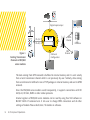
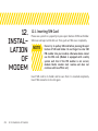
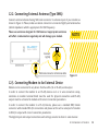
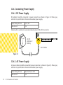
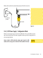
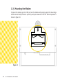
USER
MANUAL
BSC9000 SERIES
GSM/GPRS MODEMS
Energy Meters:
www.metermeter.net
Converters and Modems:
www.convertermodem.net
Optical Probes:
www.opticalprobe.net
Company Website:
www.bluskyelectronics.com
CONTENTS
1. About This Document........................................... 4
2. Safety Precautions................................................. 5
2.1. Usage of Modem in a Vehicle ...................... 5
2.2. Protection of Modem..................................... 6
3. Applied Terms and Abbreviations .....................7
4. Usage of Device...................................................... 8
5. Principle of Operation........................................... 9
6. Structure of BSC9000 Series Modem.............. 12
7. Software.................................................................. 14
7.1. Firmware........................................................... 14
7.2. Management Software: Troll .................... 14
7.2.1. Troll Main Window and Functions..... 15
7.2.2. Troll: Connection with Modem............ 16
7.2.3. Troll: Reading and Writing
Configuration of Modem...................... 18
7.2.4. Troll: Saving Configurations and
Reading Saved Configurations............22
7.2.5. Troll: Issues That Must be
Considered Before Usage.....................22
8. Communication Interfaces................................24
9. Digital Inputs/Outputs and Additional
Power Output.......................................................26
10. Notation LEDs.....................................................28
11. SMS.........................................................................29
12. Installation of Modem.......................................30
12.1. Inserting SIM Card.......................................30
12.2. Connecting External Antenna (Type
SMA)............................................................... 31
12.3. Connecting Modem to An External
Device............................................................. 31
12.4. Connecting Power Supply.........................32
12.4.1. DC Power Supply...................................32
12.4.2. AC Power Supply..................................32
12.4.3. USB Power Supply - Configuration
Mode..........................................................33
12.5. Mounting the Modem................................34
13. Troubleshooting..................................................35
13.1. Power LED of Modem is not ON..............35
13.2. GSM LED of Modem is not ON.................35
13.3. GPRS LED of Modem is not ON................35
13.4. Modem does not respond to Troll
software.........................................................35
14. Document Version.............................................36
Contents
2
1.
ABOUT
THIS
DOCUMENT
3
1. About This Document
This document includes details about installation and using of BLUSKY
BSM9000 series GSM/GPRS modems. Aktif Enerji has rights to apply
changes that are not described in this document to the system.
Our company indicates that performances of products and accessories
depend on environmental conditions in usage area.
Complete or some of this document can not be used or publish without
permission of Aktif Enerji.
• Modem propagates radio frequency (RF) signals. When modem is
being used, Rules of usage and safety precautions about RF devices should
be considered.
• Please, pay attention not to use this device in planes, hospitals,
petrol stations or places that using of GSM devices is forbidden.
• Please be sure that modem does not do parasitic effects to nearby
devices. For instance: cardiac pacemaker, medical equipments. Antenna
of modem must be kept away from computers, office equipments, home
applications etc.
• An external antenna should be connected to modem for proper
operation. Please, use antenna which is approved to use with this modem, only.
When you need to choose a new antenna, please contact with our company.
• Antenna must be far away from human body at least 26.6cm.
Please do not put antenna in metal boxes.
2.
SAFETY
PRECAUTIONS
2.1. Usage of Modem in a Vehicle
• In case of modem will be used in a vehicle, before finishing the
installIn case of modem will be used in a vehicle, before finishing the
installation, please control relevant laws and regulations of your country
about usage GSM in vehicles.
• Please, get installation of modem done to qualified staff. Owing
to possibility of occurring parasitic effects on your vehicle’s electronics,
please take authorized service of your vehicle advice.
2. Safety Precations
4
• Modem should be connected to power supply system of your vehicle by using a fuseprotected terminal in your vehicle’s fuse box.
• Please, be careful when modem gets power from battery of your vehicle. Battery may
be discharged after a while. 2.2. Protection of Modem
• To be sure about correct usage, please install and switch on your modem carefully.
• Please do not use your modem in places which has high humidity and high
temperature and do not expose your modem to hazardous chemicals, water or dust.
• Please do not try to modify or disassembly your modem. There is no any part that can
be fixed by user. This process makes warranty void.
• Please do not drop, hit or shake your modem and do not use your modem in
extremely shaky environments.
• Please do not pull cable of antenna or power, attach/remove connector by holding it.
• Please use your modem according to user’s manual. Using modem unlike as described
in this user manual will make warranty of your device void.
5
2. Safety Precations
IP address
A special number that assigned to a device working on Internet
APN
“Access Point Name” – GPRS server name that provides data
transmission
GSM
“Global System for Mobile Communications” – Voice, data
and text message package transmission technology which is
commonly used in cell phone
GPRS
“General Packet Radio Service”, technology which is applied for
data package transmission in GSM networks
TCP
“Transmission Control Protocol” – A data transmission
flow control which is applied between devices working in a
network. Data is sent in packages. This protocol guarantees
data transmission correctness.
Package
Transmission
The transmission that data is not sent continuously, they are
sent in pieces which are named as package.
SIM
“Subscriber Identity Module” – An Identity card, special for
subscriber
SMS
“Short Message Service” – A service to send short text
message.
3.
APPLIED
TERMS
AND
ABBREVIATIONS
3. Applied Terms and Abbreviations
6
4.
USAGE
OF
DEVICE
BSC9000 series modems are multipurpose GSM/GPRS modems that make
data transmission possible by using any network of an operator which
works in 900/1800MHz or 850/900/1800/1900MHz bands. Modem is
designed to work with any device that has RS-232 or RS-485 type serial
interface.
Modem provides remote reading of electricity, water, gas meters and
other measuring devices having serial port by GPRS.
On the side of GPRS network, connection is performed in TCP/IP protocols.
On the side of device, connection is established with RS-232 and RS-485
type serial outputs.
BSC9000 series modems are also equipped with one digital input and one
digital output. By using this features, BSC9000 series modems can get
signals from a door detector, alarm unit or any device that has a digital
output. Status of those signals can be reported as an SMS or they can be
read remotely by using GSM/GPRS communication protocol or locally by
using service connection.
7
4. Usage of Device
BSC9000 series modems work as TCP server or client in GPRS Networks.
IP address of modem is determined by used SIM card. Modem is started
as a server or client device according to its configuration, automatically.
When the modem is started, it controls SIM card, signal strength, and GSM
network availability then it logins to APN by using previously configured
login information. The relevant service is started by successful login to
APN.
Modem has features to provide data flow diagnostics. If the signal strength
is too low or the data cannot be transmitted for a certain period of time
or there is a time period which is previously defined by the user to restart
the modem, modem reinitiates the GPRS network connection and logins
to APN again.
BSC9000 series modems work transparently. It makes communication
possible independent from the connection’s protocol with all transmission
channels. Figure 1 shows all existing transmission channels.
The modem postpones the restart procedure if there is a data
transmission and/or USB configuration cable is actively connected.
5.
PRINCIPLE
OF
OPERATION
NOTE
The data coming from GPRS network is buffered in internal memory and it
is sent serially from a local transmission channel which is set previously by
user. Similarly, data coming from serial channel is buffered in size of TCP
packages in internal memory and sent to GPRS network.
5. Principle of Operation
8
Digital input/output
GPRS
Channel
RS-232
RS-485
Figure 1.
Existing Transmission
Channels in BSC9000
series modems
Database
USB Local
Configuration
SMS
Channel
The data coming from GPRS network is buffered in internal memory and it is sent serially
from a local transmission channel which is set previously by user. Similarly, data coming
from serial channel is buffered in size of TCP packages in internal memory and sent to GPRS
network.
Since the BSC9000 series modems work transparently, it supports connections with IEC
62056-21, IEC1142, DLMS or other similar protocols.
Internal registers of BSC9000 series modems can be read by using free Troll software or
BLUSKY ASCII AT command sets. It lets user to change GPRS connections and all other
settings of modem. Please check item 7 for details on software.
9
5. Principle of Operation
It is obligatory to authenticate to the modem with a valid username and password in order
to change or read settings. Also, five different IP address and Subnet Masks can be set as
black list or white list filter to improve security. Terminal block of the modem can also be
sealed and manipulations to terminal cover can be logged thus reliability of the modem is
maximized.
BSC9000 series modems can also send information by using SMS beside using the serial
interfaces. SMS messages can be sent according to any of events encountered below:
• Modem terminal cover is opened or closed
• Violation of white list or black list filter
• Authentication attempt by using wrong username or password
• A signal change is detected (ON or OFF) in digital input of modem
• GSM signal strength is below user defined threshold level
The digital input in BSC9000 series modems can be used to collect external alarm signals,
to cumulate the pulses of other gas or water meters, to detect instantly door or cubicle
openings or similar events. Also the digital output in modem lets user to control external
alarms, motors or similar devices or to generate clock synchronization pulses. It is settable
to give single pulse or continuous ON signal or continuous OFF signal.
5. Principle of Operation
10
6.
STRUCTURE OF
BSC9000
SERIES
MODEM
BSC9000 series modems can be mounted on a 35mm DIN Rail directly or
can be hanged on a wall. All connections, SIM card slot and connection
terminals are covered with a sealable terminal cover.
Design of modem provides easy connection, It is easy to reach all
connection terminals and SIM card slot without demounting the modem
by opening sealable terminal cover. Device has an SMA antenna connector
for external antenna connection. Long antenna cables can be used where
GSM signal strength is low to improve GSM signal strength.
Internal structure of BSC9000 series modems consists of the following
blocks: power supply, transmission section that provides data transmission
by using GSM/GPRS, RS-232 and RS-485 to communicate with a local
device, inputs/outputs, USB input for local configuration and ARM
Cortex-M3 processor unit that controls all processes in modem. Internal
GSM/GPRS module works at 900/1800Mhz or 850/900/1800/1900Mhz.
Figure 2.
Front view of GSM/GPRS
Communication Module
11
6. Structure of BSC9000 Series Modem
Figure 3.
Back view of GSM/GPRS
Communication Module
Figure 4.
Connector Connection
view of GSM/GPRS
Communication Module
Power input of modem accepts voltages between 9-54 DC or 265V AC, 50-60Hz. It provides
ease of use by working with different kind of power supplies according to user needs. Also,
modem supplies 12 Volt DC Voltage output which is isolated from the system galvanically.
This additional isolated voltage supply lets users to use digital inputs and outputs without
need of any additional power supply to complete the input and/or output circuit.
6. Structure of BSC9000 Series Modem
12
7.
SOFTWARE
7.1. Firmware
There is special software in nonvolatile memory of Modem. This
software is embedded on an army level stable operating system. Also
the configuration information are saved in two different memory areas in
modem for safety. This software executes all operational processes such
as GSM/GPRS connections, data transmission with serial ports, showing
operating status with LEDs and showing situations of inputs/outputs etc.
BSC9000 series modems executes all processes automatically once
the power supply is connected without giving additional commands.
Configuration status is controlled on every startup (disk check), if
original configuration is defected, configuration is reconstructed from a
backup and modem continues to work without any interruption. Device
configuration is saved in a nonvolatile memory so that in case of restart or
re-run of the device, all configurations remain unchanged.
7.2. Management Software: Troll
“Troll” software is used to display configuration and operation status of modem and to
change all operational parameters of BSC9000 series modems. It runs on computers
with Windows operating system and it is supplied with a modem free of charge. It
provides executing service commands, monitoring operation status of device, reading
and editing configurations, loading factory settings, restarting of device, updating
firmware etc. Also, this program lets user to set all parameters of modem.
13
7. Software
Troll can connect BSC9000 series modems by using USB service connection locally
(Communication Parameters: 115200 Baud, 8N1( 8 data bits, 1 stop bit, Parity None)) or
remotely via GPRS connection by using TCP/IP protocol.
7.2.1. Troll Main Window and Functions
Install Troll software like any other Windows ( it works on Win7, Win Vista, XP … both in
64bit and 32bit systems) based software and run it. The window on Figure 5 will appear.
Options on this screen is described below:
Serial, TCP selections
defines the connection
channel that will be used
to connect the modem
Device manager
can be opened
and devices with
COM ports can
be seen by using
See COM Ports
Configuration Settings Configurations
COM Port that
group helps to set or can be saved to a
will be used for If Communication read parameters of
file or previously
communication will be established modem. It is possible to saved configuis choosen from
over TCP, IP
rations can be
read or write settings
Connection COM address and Port on single page or all opened by using
Port
is entered here settings in software
this menu
Connection to modem
is realized according to
the given parameters by
using Connect button
Related settings are
displayed in Settings
tab pages
Information Bar gives
information about
current processes
Figure 5
7. Software
14
7.2.2. Troll: Connection with Modem
In Connection Details group, there are settings for starting a proper communication with the
modem. Options of this menu are shown in Figure 6:
Figure 6
In order to start a communication with the modem, a few basic settings should be done in
software.
• Local Configuration with Serial Communication: First of all, serial option should be
checked. After USB cable is connected and modem usb driver is installed, proper COM port
should be chosen. To choose proper COM port, please click on See COM Ports button and
view loaded COM ports on your computer. Available COM ports can be seen under Ports
(COM & LPT) title of Device Manager window as shown in Figure 7.
Please close the Device Manager window after being sure about COM port of the modem and
select the related COM port from Connection COM port combo box.
• Remote Configuration with TCP Communication: First of all, TCP option should be
checked. After that IP address and Port number of modem should be entered. IP address is
determined by inserted SIM card and APN information thus before setting up the modem
for the first usage, an IP address information cannot be achieved (IP info can also be get
from GSM SIM card provider). Port number can be set independent from IP address in
configuration. Default port number is 10001.
15
7. Software
Figure 7
In order to be able to connect the modem remotely by using TCP/IP
protocol, the modem must operate in server mode.
NOTE
7. Software
16
7.2.3. Troll: Reading and Writing Configuration of Modem
Once the modem connection is established by using the relevant login information,
configuration settings and identity information of modem can be read and settings that
are permitted to change can be updated. In order to realize those operations buttons in
Configuration Settings group can be used. Menu options are shown in figure 8:
Figure 8
With Read button all related information can be read. Read information are reported as tabs;
System Information Tab
The basic information about the modem can be seen in this tab. Additionally, signal strength
level can be monitored. Also the time of modem and name of modem can be set from this tab.
17
7. Software
Serial Port Settings Tab
In this tab, active local port of the modem and communication parameters of this port can
be set.
Network Settings Tab
PIN information of SIM card, APN settings, operation status of modem and restarting time of
modem when there is no data transmission can be determined in this tab.
7. Software
18
Security Settings Tab
White list or black list filter settings can be done in this tab. If black list is activated, devices that have
IP address and Subnet Mask which is defined in blacklist are not allowed to establish connection with
the modem. Also if white list is activated, only the devices having IP addresses and Subnet masks that
are defined in While List are allowed to establish connection with the modem.
SMS Settings Tab
The modem can send reports to the predefined telephone number via SMS according to the
predefined event occurrence during operation of the modem. User can get SMS from the
modem when the selected event in this tab occurred during operation.
19
7. Software
Input/Output Settings Tab
In this tab, digital inputs and outputs of modem can be controlled and related settings can be done.
Process Log Tab
In this tab, user can monitor the history of program usage and realized commands.
7. Software
20
7.2.4. Troll: Saving Configurations and Reading Saved
Configurations
Configurations can be saved into a file so that same configurations can be applied to multiple
modems easier and faster and also used configurations can be archived. Current settings of
modem can be saved in a file or previously saved configurations can be opened by options in
Save/Open Configuration menu group. Menu options are shown in Figure 9:
Figure 9
7.2.5. Troll: Issues That Must be Considered Before Usage
• For the first connection, the user must use local serial connection method. If the
network settings are done properly, the modem can get a valid IP and then it will be available
to connect the modem remotely over GPRS by using the IP and port information that are also
displayed in System Information tab. The modem cannot attach itself to GPRS channel and
get a valid IP address unless valid APN login information is set in the modem. Please contact
your SIM card supplier if you are not sure about your APN settings.
• APN name login info may be different according to SIM card operator that is used.
User should know the APN name to provide proper connection. APN name can be learned
from operator.
• There are two arrow under the Configuration Settings group buttons of Troll. User
can reach extra functions for reading and writing configurations by clicking them.
21
7. Software
Figure 10
• Modem can be restarted or factory settings can be restored by using the Admin
Tools tab.
• SIM PIN code consists of maximum 4 digits. User should pay attention to enter code
correctly. If the PIN is entered incorrectly, modem can detect it and blocks the initiation
process until correct PIN entrance, thus also avoid blocking SIM card.
• Modem (restart) Reset Time Period should be between 5 and 240 (4 Hour) minutes.
The modem reset procedure is postponed if USB local configuration is connected and active
and/or there is data transmission.
7. Software
22
8.
COMMUNICATION
INTERFACES
23
8. Communication Interfaces
To use with external serial devices, BSC9000 series modems are equipped
with RS-232 and RS-485 serial interfaces.
Modem enables connecting multiple devices. The number of devices to
be connected is defined by standards of serial ports. RS-485 allows to
connect up to 32 devices and RS-232 lest connecting single device to the
modem.
Single device or several addressable devices can be connected to BSC9000
series modems by using serial connections.
• RS-232 – asynchronous, bidirectional, five-wire ( RTS and CTS are
supported, they are not mandatory to connect if hardware flow control is
not used) serial interface
DB9M Pin # BSC9000 RS-232
1
NA
2
RXD (Data In)
3
TXD (Data Out)
4
NA
5
GND
6
NA
7
RTS (HW Flow Control Output)
8
CTS (HW Flow Control Input)
9
NA
1 2 3 4 5
6 7 8 9
• RS-485 – asynchronous, bidirectional, two-wire or four-wire interface in “half
duplex” mode
BSC9000 RS485
Connection
Serial Device
RX+
TX+
RX-
D−/Rx−
RX-
D+/Rx+
RX+
TX-
Tx−
TX+
Tx+
RS-422 or 4-wire RS-485 Mode
TX2-wire RS-485 Mode
D+
D+
D-
D-
There are also LEDs which visualize the transmission of data over serial interfaces in front
panel of modem. “TX” LED blinks when data is transmitted from the modem and “RX” LED
blinks when the modem receives data.
8. Communication Interfaces
24
BSC9000 series modems are equipped with digital input and outputs and
additional power output to be used with those input and outputs. The digital
input can be used to collect external alarm signals, to cumulate the pulses
of other gas or water meters, to detect instantly door or cubicle openings or
similar events. Also the digital output in modem lets user to control external
alarms, motors or similar devices or to generate clock synchronization pulses.
Input: Optomosfet: Works with 9 - 240 Volts AC/DC, 60mA
Output: Solid state relay: Works with 9 - 240 Volts AC/DC, 120mA
Power Output: 12VDC, max power 1W, galvanically isolated from the
system
Both input and output do not have any polarity.
I-1
I-1
O-1
O-1
Pow-12V DC
GND
Sample input connections:
I-1
I-1
O-1
O-1
Pow-12V DC
GND
9.
DIGITAL
INPUTS/
OUTPUTS
AND
ADDITIONAL
POWER
OUTPUT
Max 240 V AC-DC
Load
25
9. Digital Inputs/Outputs and Additional Power Output
Load
Load
I-1
I-1
O-1
O-1
Pow-12V DC
GND
I-1
I-1
O-1
O-1
Pow-12V DC
GND
Sample output connections:
Load
There are also LEDs which visualize the input and output contact states in front panel of
modem. «Input» LED turns on when signal is detected in input circuit and «Output” LED
turns on when output circuit is closed (set to ON (High) mode).
9. Digital Inputs/Outputs and Additional Power Output
26
10.
NOTATION
LEDS
LEDs are located on front panel of modem and they give information about
operation status. Following cases can be observed without connecting an
external device to the modem;
• Power input is detected
• Correct login to SIM card (Modem is ready to use, GSM connection
is ready)
• GPRS connection is established
• Data transmission to GPRS layer from serial input (data from
modem)
• Data transmission to serial input from GPRS layer (data to modem)
• Input circuit is closed
• Output circuit is closed
• Signal strength of GSM (3 LEDs)
When the related state occurs, related LEDs turn on and when the state
changes, related LEDs turn off. For signal strength, there are three LEDs;
• 1 led ON: Signal strength <= -93dbm ( %40)
• 2 led ON: Signal strength <= -69dbm ( %80)
• 3 led ON: Signal strength > -69dbm (%100)
Also there are 2 additional LEDs under the terminal cover in order to show:
• USB connection is ready to use
• USB connection is physically done
27
10. Notation LEDs
BSC9000 series modems lets user to get information from modem via SMS
messages. User can get SMS messages about following events:
•
•
•
•
•
Modem terminal cover is opened/closed
Violation of white list or black list filter
Authentication attempt by using wrong username or password
A signal change is detected (ON or OFF) in digital input of modem
GSM signal strength is below user defined threshold level
11.
SMS
Settings such as message center number, in which event the message will
be sent, telephone number which the message will be sent can be set by
using Troll software or BLUSKY ASCII AT commands.
11. SMS
28
12.
INSTALLATION
OF
MODEM
12.1. Inserting SIM Card
Please use a pencil or a paperclip to press eject button of SIM card holder.
SIM cover will eject a little bit out. Then, pull out SIM cover completely.
NOTE
Do not try to pull up SIM card before pressing the eject
button of SIM card holder. Do not forget to enter SIM
PIN number into your modem, otherwise device cannot
use the SIM card. (Modem is equipped with a safety
system such that if the PIN number is not correct,
modem blocks modem start routine and does not
continue until new PIN is set).
Insert SIM card to its holder and be sure that it is inserted completely.
Insert SIM connector to its slot again.
29
12. Installation of Modem
12.2. Connecting External Antenna (Type SMA)
Connect external antenna having SMA male connector to antenna input of your modem as
shown in Figure 11. Please, make sure about connector is connected tightly and antenna has
50ohm impedance which is appropriate for GSM frequency.
Please use antennas designed for GSM devices. Inappropriate antennas
will affect communication negatively and will damage your modem.
NOTE
Connect
tightly
SMA male connector of antenna cable
Figure 11
12.3. Connecting Modem to An External Device
Modem can be connected to any device that have RS-232 or RS-485 serial output.
In order to connect the modem to an RS-485 device via 2 or 4 wire connection setup,
notations on modem terminal block must be used for physical connection and RS-485
output must be activated in modem with correct connection parameters.
In order to connect the modem to a RS-232 device, please use a standard DB9 Female
connector with standard RS-232 connections and please set the active serial port of modem
to RS-232 output with correct connection parameters.
The digital input and output connections and settings can also be done in same manner.
12. Installation of Modem
30
12.4. Connecting Power Supply
12.4.1. DC Power Supply
DC adapter should be connected to power connector as shown in Figure 12. Please, pay
attention to specifications that are below about power supply.
Input Voltage Interval
9V – 56V
Max Current
2A
Modem will be switched on automatically and power LED will be turned on.
AC-DC
Adapter or
Battery
End of Cable
Figure 12
12.4.2. AC Power Supply
AC power cables should be connected to power connector as shown in Figure 13. Please, pay
attention to specifications that are below about power supply.
31
Input Voltage Interval
85-265V AC, 50-60Hz
Max Current
2A
12. Installation of Modem
Modem will be switched on automatically and power LED will be turned on.
85-265V AC,
50-60Hz
End of Cable
Figure 13
12.4.3. USB Power Supply - Configuration Mode
Modem can also be power by just connection the USB cable. In this case the GPRS connection
layer will not be functional. This mode is supplied to make easy and fast configurations via
just connecting USB cable.
Features related to GPRS module like reading signal strength, the IMEI
number and the message center number will not be available in this mode.
NOTE
12. Installation of Modem
32
12.5. Mounting the Modem
To mount the modem, put it to DIN rail, lean the module with springs against the lower edge
of DIN rail and lastly lift device up firmly and press towards to the rail. DIN rail aparatus is
shown in Figure 14:
Figure 14
33
12. Installation of Modem
13.1. Power LED of Modem is not ON
Check if the modem is connected to power supply properly and output
nominal values are covered.
13.2. GSM LED of Modem is not ON
Check if a valid SIM card is used and it is inserted properly.
Check if the SIM card is blocked or not.
Check if the SIM pin number is set properly or not.
13.3. GPRS LED of Modem is not ON
13.
TROUBLESHOOTING
Check if the external antenna is connected properly.
Check if the GSM network signal is available enough where the modem is
mounted.
Check if the APN parameters are entered correctly or not.
13.4. Modem does not respond to Troll software
Check if the USB cable is connected properly.
Check if the COM setting of software is done correctly and driver is installed.
Check if the USB cable is connected after the USB ready LEDs are ON.
13. Troubleshooting
34
14.
DOCUMENT
VERSION
Created: Mart 2012
Update: January 2013
Version: 2
Updates since last version
1. The changes with the new plastic mould and new PCB functionalities
has been added
For Questions, comments and suggestions, please contact us.
Aktif Enerji Insaat Sanayi ve Ticaret Ltd. Co.
Address: 2535 Sokak No:6 Umit Mah. Umitkoy/Yenimahalle/Ankara/TURKEY
Tel: +90 312 473 1840(pbx) Website: www.aktifenerji.com.tr
Fax: +90 312 473 1841
e-mail: [email protected]
29
14. Document Version