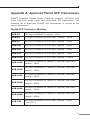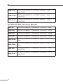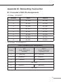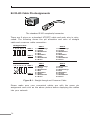
1
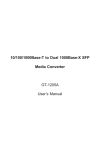
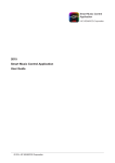
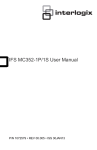
Industrial 10/100/1000BASE-T to 100/1000BASE-X SFP Media Converter IGT-805AT Industrial 10/100/1000BASE-T to 2 100/1000BASE-X SFP Media Converter IGT-1205AT User's Manual Trademarks Copyright © PLANET Technology Corp. 2015. Contents are subject to revision without prior notice. PLANET is a registered trademark of PLANET Technology Corp. All other trademarks belong to their respective owners. Disclaimer PLANET Technology does not warrant that the hardware will work properly in all environments and applications, and makes no warranty and representation, either implied or expressed, with respect to the quality, performance, merchantability, or fitness for a particular purpose. PLANET has made every effort to ensure that this User’s Manual is accurate; PLANET disclaims liability for any inaccuracies or omissions that may have occurred. Information in this User’s Manual is subject to change without notice and does not represent a commitment on the part of PLANET. PLANET assumes no responsibility for any inaccuracies that may be contained in this User’s Manual. PLANET makes no commitment to update or keep current the information in this User’s Manual, and reserves the right to make improvements to this User’s Manual and/or to the products described in this User’s Manual, at any time without notice. If you find information in this manual incorrect, misleading, or incomplete, we would appreciate your comments and suggestions. FCC Warning This equipment has been tested and found to comply with the limits for a Class A digital device, pursuant to Part 15 of the FCC Rules. These limits are designed to provide reasonable protection against harmful interference when the equipment is operated in a commercial environment. This equipment generates, uses, and can radiate radio frequency energy and, if not installed and used in accordance with the Instruction manual, may cause harmful interference to radio communications. Operation of this equipment in a residential area is likely to cause harmful interference in which case the user will be required to correct the interference at his own expense. CE Mark Warning This is a Class A product. In a domestic environment, this product may cause radio interference, in which case the user may be required to take adequate measures. WEEE Warning To avoid the potential effects on the environment and human health as a result of the presence of hazardous substances in electrical and electronic equipment, end users of electrical and electronic equipment should understand the meaning of the crossed-out wheeled bin symbol. Do not dispose of WEEE as unsorted municipal waste and have to collect such WEEE separately. Revision PLANET Industrial 10/100/1000BASE-T to 1/2 100/1000BASE-X SFP Media Converter User's Manual FOR MODELS: IGT-805AT / IGT-1205AT REVISION: 1.0 (MARCH, 2015) Part No: EM-IGT_805AT_1205AT_v1.0 (2350-AH1210-001) Table of Contents 1.Introduction............................................................................... 6 1.1 Package Contents................................................................ 6 1.2 Product Overview................................................................. 6 1.3 Product Features.................................................................. 7 1.4 Product Specifications.......................................................... 9 2. Hardware Description.................................................................11 2.1 Physical Dimensions............................................................11 2.2 Converter Front Panel.........................................................13 2.3 LED Indicators....................................................................14 2.4 Converter Upper Panel........................................................16 3.INSTALLATION..........................................................................17 3.1 Quick Installation Steps.......................................................17 3.2 Mounting Installation...........................................................18 3.2.1DIN-rail Mounting......................................................18 3.2.2Wall-mount Plate Mounting.........................................20 3.3 Wiring the Power Inputs......................................................21 3.4 Wiring the Fault Alarm Contact............................................22 3.5 Cable Connection................................................................23 3.6 Redundancy Overview (IGT-1205AT only).............................27 4.Applications..............................................................................28 5.Troubleshooting.........................................................................29 6. Cable Connection Parameters.....................................................30 Appendix A: Approved Planet SFP Transceivers..................................31 Appendix B: Networking Connection.................................................33 B.1 Converter’s RJ45 Pin Assignments.........................................33 B.2 RJ45 Cable Pin Assignments.................................................34 1.Introduction 1.1 Package Contents The term “Industrial Gigabit Media Converter” mentioned in this user’s manual also means the IGT-805AT / IGT-1205AT. Check the contents of your package for the following parts: zz Industrial Gigabit Media Converter x 1 zz User's Manual x 1 zz DIN Rail Kit x 1 zz Wall Mount Kit x 1 If any of these are missing or damaged, please contact your dealer immediately; if possible, retain the carton including the original packing material, and use them again to repack the product in case there is a need to return it to us for repair. 1.2 Product Overview Flexibility and Network Distance Extension Solution The IGT-805AT / IGT-1205AT Industrial Gigabit Media Converter is equipped with one 10/100/1000BASE-T auto-negotiation port and one / two 100/1000X SFP slots. The SFP slots are compatible with 1000BASE-X or 100BASE-FX through SFP (Small Form Factor Pluggable) fiber-optic transceiver. The IGT-805AT SFP slot automatically detects the 100BASE-FX or 1000BASE-X SFP transceiver while the IGT-1205AT’s two SFP slots allow changing the operation speed mode with its built-in DIP switch. The fiber optical uplink capability guarantees the throughput to all nodes hooked into the network and the Gigabit Ethernet distance can be extended from 550 meters (multi-mode fiber cable) up to 10/20/30/40/50/60/70/120 kilometers (single-mode fiber cable). Also, the Fast Ethernet distance can be extended from 2km (multi-mode fiber cable) up to 20/40/60 kilometers (single-mode fiber cable). They are well suited for applications within the factory data centers and distributions. 6 Environmentally Hardened Design With IP30 industrial metal case, the Industrial Gigabit Media Converter provides a high level of immunity against electromagnetic interference and heavy electrical surges which are usually found on plant floors or in curbside traffic control cabinets. It also possesses an integrated power supply source with a wide range of voltages (12 to 48V DC or 24V AC) for worldwide high availability applications requiring dual or backup power inputs. Being able to operate under the temperature range from -40 to 75 degrees C, the Industrial Gigabit Media Converter can be placed in almost any difficult environment. The compact IP30 standard metal case of Industrial Gigabit Media Converter allows either DIN rail or wall mounting for efficient use of cabinet space. Robust Gigabit Media Converter Performance The IGT-805AT / IGT-1205AT offers wire-speed packets transfer performance without risk of packet loss. The high data throughput of the device makes it ideal for most Gigabit environments. With a 4/6Gbps internal fabric and featuring auto negotiation support in its Gigabit port, the IGT-805AT / IGT-1205AT Industrial Gigabit Media Converter can handle large amounts of data in a secure topology linking to a backbone or high capacity servers. Adjustable 3-Port Switch Mode or 2 Fiber Port Redundant Mode (IGT-1205AT only) Via the built-in DIP-switch, the two SFP fiber interfaces of IGT-1205AT can be configured as Ethernet switch mode or fiber redundant mode. With the Ethernet switch mode, it can operate Store-and-Forward mechanism with high performance; with the 2-port fiber redundant mode, it provides redundancy of link for highly critical Ethernet applications. The redundant mode supports auto-recover function. If the destination port of a packet is link-down, it forwards the packet to the other port of the backup pair. 1.3 Product Features IGT-805AT Physical Port 1-port 10/100/1000BASE-T RJ45 with auto MDI / MDI-X function 1 SFP interface, 100/1000BASE-X dual mode (auto detection) 7 IGT-1205AT Physical Port 1-port 10/100/1000BASE-T RJ45 with auto MDI / MDI-X function 2 SFP interfaces, 100/1000BASE-X dual mode (DIP switch control) Layer 2 Features IEEE 802.3 / 802.3u / 802.3ab / 802.3z Ethernet standard compliant Supports auto-negotiation and 10/100Mbps half / full duplex and 1000Mbps full duplex mode Prevents packet loss with back pressure (hjalf-duplex) and IEEE 802.3x pause frame flow control (full-duplex) 9K jumbo frame size support Automatic address learning and address aging Industrial Case / Installation Slim type IP30 metal case DIN rail and wall-mount design Redundant power design - 12 to 48V DC, redundant power with polarity reverse protect function - AC 24V power adapter acceptable Supports EFT protection for 6000 VDC for power line Supports 6000 VDC Ethernet ESD protection -40 to 75 degrees C operating temperature Fiber Port Redundancy (IGT-1205AT only) Link status auto-detect and redundant on dual ports with the same connector type Only when primary port is activated, the backup port is blocked. When primary port link fails, the traffic will swap to backup port automatically. Once the primary port status is back to link up, the traffic will swap from backup port to primary port. 8 1.4 Product Specifications Model IGT-805AT IGT-1205AT Hardware Specifications Copper Interface Fiber Optic Interfaces 1 x 10/100/1000BASE-T 1 x 10/100/1000BASE-T RJ45 RJ45 1 x 1000BASE-SX/LX/ BX SFP interface. Compatible with 100BASE-FX SFP 2 x 1000BASE-SX/ LX/BX SFP interfaces (Port-1 and Port-2) Compatible with 100BASE-FX SFP Connector Removable 6-pin terminal block Pin 1/2 for Power 1; Pin 3/4 for fault alarm; Pin 5/6 for Power 2 Alarm Provides one relay output for power failure Alarm Relay current carry ability: 1A @ DC 24V Power Requirements DC 12~48V, Redundant power with polarity reverse protection function. AC 24V Power Adapter Power Consumption / Dissipation 3.3 watts/11BTU 4.8 watts/16BTU 32 x 87 x 135mm 32 x 87 x 135mm 458g 505g Dimensions (W x D x H) Weight Enclosure Installation IP30 type metal case DIN rail kit and wall-mount ear ESD Protection 6KV DC EFT Protection 6KV DC 9 Converter Specifications Processing Scheme Store-and-Forward Fabric Throughput (packet per second) 4Gbps 6Gbps 2.97Mpps 4.46Mpps Back pressure for half duplex. IEEE 802.3x pause frame for full duplex Flow Control Maximum Transmission Unit 9216bytes Standards Conformance Standards Compliance IEEE IEEE IEEE IEEE IEEE 802.3 Ethernet 802.3u Fast Ethernet 802.3ab Gigabit Ethernet 802.3z Gigabit Ethernet 802.3x full-duplex flow control Regulation Compliance FCC Part 15 Class A, CE Stability Testing IEC60068-2-32 (free fall) IEC60068-2-27 (shock) IEC60068-2-6 (vibration) Environment Temperature Operating: -40~75 degrees C Storage: -40~75 degrees C Humidity Operating: 5~95% (Non-condensing) Storage: 5~95% (Non-condensing) 10 Bottom View 10/100/1000T 100/1000X P2 FAULT IGT-805AT 1000 LNK/ACT LNK/ACT P1 Top View Rear View Mounting Kit DIN-Rail Kit Mounting Kit 2.Hardware Description 2.1 Physical Dimensions IGT-805AT dimensions (W x D x H): 32 x 87 x 135mm Side View Front View 11 Mounting Kit DIN-Rail Kit Rear View Mounting Kit IGT-1205AT dimensions (W x D x H): 32 x 87 x 135mm V1+ V2PWR2 V2+ 1 2 3 Mode ON Port 1 Port 2 Input DC 12~48V, AC 24V 1 2 3 4 5 6 V1PWR1 Fault ON 100FX Top View Side View OFF 1000X 100FX 1000X Redundant Switch IGT-1205AT 100 1000 LNK/ACT LNK/ACT 3 LNK / ACT SFP 1000X 10/100/1000T 2 1 SFP Bottom View 12 LNK / ACT 1000X P1 P2 FAULT Front View 2.2 Converter Front Panel Figures 2-1 and 2-2 show the front panels of the Industrial Gigabit Media Converter. P1 P1 P2 FAULT P2 FAULT 1000X 1 SFP LNK / ACT 1000X 100/1000X LNK/ACT 2 SFP LNK / ACT 10/100/1000T 3 10/100/1000T LNK/ACT 100 1000 LNK/ACT LNK/ACT 1000 IGT-805AT IGT-1205AT Figure 2-1: IGT-805AT Front Panel Figure 2-2: IGT-1205AT Front Panel 13 2.3 LED Indicators System LED Color Function P1 Green Lit: indicates power 1 has power. P2 Green Lit: indicates power 2 has power. FAULT Green Lit: indicates either power 1 or power 2 has no power. Per 10/100/1000BASE-T Port (IGT-805AT) LED Color Function Lit: indicates that the Gigabit Ethernet Port is successfully connecting to the network at 10/100/1000Mbps. LNK/ACT Green Blinking: indicates that the Gigabit Ethernet Port is actively sending or receiving data over that port. Lit: indicates the link through that port is successfully established at 1000Mbps. 1000 Green Off: indicates the link through that port is successfully established at 10/100Mbps. 14 Per 10/100/1000BASE-T Port (IGT-1205AT) LED Color Function Lit: indicates the link through that port is successfully established at 100Mbps or 10Mbps. 100 Orange LNK/ACT Blinking: indicate that the Switch is actively sending or receiving data over that port. Off: indicates the link through that port is successfully established at 1000Mbps. Lit: indicates the link through that port is successfully established at 1000Mbps. 1000 Green LNK/ACT Blinking: indicates that the Switch is actively sending or receiving data over that port. Off: indicates the link through that port is successfully established at 10/100Mbps. Per 100 / 1000BASE-X SFP Slot LED Color Function Lit: indicates the link through that port is successfully established at 100Mbps or 1000Mbps. LNK/ACT Green Blinking: indicates that the Converter is actively sending or receiving data over that port. 15 2.4 Converter Upper Panel The upper panel of the IGT-805AT and IGT-1205AT consist of one terminal block connector within two DC power inputs, and the IGT-1205AT also provides 3 DIP Switches for 100/1000X fiber support on two SFP slots and fiber redundant function. Figure 2-3 shows the upper panel of the IGT-1205AT V1+ Fault V2PWR2 V2+ 1 ON Port 1 Input DC 12~48V, AC 24V 1 2 3 4 5 6 V1PWR1 Port 2 2 Mode 3 ON OFF 100FX 1000X 100FX 1000X Redundant Switch Figure 2-3: IGT-1205AT Upper Panel The 3 DIP switch settings and descriptions 1 2 3 ON Port 1 (DIP 1) Port 2 (DIP 2) Fiber Mode (DIP 3) ON OFF 100FX 1000X 100FX 1000X Fiber Redundant Switch The fiber redundancy function explains in chapter 3.6 Redundancy Overview. 16 3.INSTALLATION This section describes the functionalities of the Industrial Gigabit Media Converter’s components and guides you to how to install it on the desktop. Basic knowledge of networking is assumed. Please read this chapter completely before continuing. 3.1 Quick Installation Steps Step 1: Unpack the Industrial Gigabit Media Converter. Step 2: Check whether the DIN-rail is screwed on the Industrial Gigabit Media Converter. (Please refer to DIN-rail Mounting section for DIN-rail installation if the DIN-rail is not screwed on the Industrial Gigabit Media Converter). If you want to wall-mount the Industrial Gigabit Media Converter, then please refer to the Wall-mount Plate Mounting section for wall-mount plate installation. Step 3:To hang the Industrial Gigabit Media Converter on the DIN-rail track or wall, please refer to the Mounting Installation section. Step 4: Power on the Industrial Gigabit Media Converter. (Please refer to the Wiring of the Power Inputs section for power input) The power LED on the Industrial Gigabit Media Converter will light up. Please refer to the LED Indicators section for the functions of LED lights. Step 5: Prepare the twisted-pair, straight-through Category 5 cable for Ethernet connection. Step 6: Insert one side of Category 5 cable into the Industrial Gigabit Media Converter Ethernet port (RJ45 port) while the other side of Category 5 cable into the network devices' Ethernet port (RJ45 port), e.g., switch, PC or server. The UTP port (RJ45) LED on the Industrial Gigabit Media Converter will light up when the cable is connected with the network device. Please refer to the LED Indicators section for the functions of LED lights. Step 7: When all the connections are all set and LED lights all show normally, the installation is complete. 17 3.2 Mounting Installation This section describes how to install the Industrial Gigabit Media Converter and makes connections to it. Please read the following topics and perform the procedures in the order being presented. Note In the installation steps below, this Manual uses IGS-801 (PLANET 8-port Industrial Gigabit Switch) as the example. However, the steps for PLANET Industrial Switch and Industrial Media Converter are similar. 3.2.1 DIN-rail Mounting The DIN-rail is screwed on the Industrial Gigabit Media Converter when is out of factory. When replacing the wall-mount application with DIN-rail application on Industrial Gigabit Media Converter, please refer to the following figures to screw the DIN-rail on the Industrial Gigabit Media Converter. To hang the Industrial Gigabit Media Converter, follow the following steps: Step 1: Screw the DIN-rail on the Industrial Gigabit Media Converter. 18 1 2 Step 2: Lightly insert the DIN-rail into the track. Step 3: Make sure the DIN-rail is tightly secured on the track. Step 4:Please refer to the following procedures to remove the Industrial Gigabit Media Converter from the track. 1 2 19 Step 5: Lightly pull out the bottom of the DIN-Rail from the track to remove. 3.2.2 Wall-mount Plate Mounting To install the Industrial Gigabit Media Converter on the wall, please follow the instructions described below. Step 1:Remove the DIN-Rail from the Industrial Gigabit Media Converter; loosen the screws to remove the DIN-rail. Step 2: Place the wall-mount plate on the rear panel of the Industrial Gigabit Media Converter. Step 3:Use the screws to screw the wall-mount plate on the Industrial Gigabit Media Converter. Step 4: Use the hook holes at the corners of the wall-mount plate to hang the Industrial Gigabit Media Converter on the wall. Step 5: To remove the wall-mount plate, reverse the steps above. 20 3.3 Wiring the Power Inputs The 6-contact terminal block connector on the top panel of Industrial Gigabit Media Converter is used for two DC redundant power inputs. Please follow the steps below to insert the power wire. 1.Insert positive / negative DC power wires into contacts 1 and 2 for POWER 1, or 5 and 6 for POWER 2. V1- V1+ V2- V2+ OFF 1000X 1000X Switch ON 100FX 100FX Redundant Input DC 12~48V, AC 24V 2 3 Mode 1 Port 2 1 2 3 4 5 6 Note V2+ Port 1 V2PWR2 Fault PWR1 V1- V1+ ON The above top panel is based on IGT-1205AT. The 6-contact terminal block connector is the same as that of IGT-805AT. But the IGT-805AT does not provide 3 DIP switches. 2.Tighten the wire-clamp screws for preventing the wires from loosening. 1 2 Power 1 + 3 Fault 4 5 6 Power 2 + 21 Note The wire gauge for the terminal block should be in the range between 12 and 24 AWG. 3.4 Wiring the Fault Alarm Contact The fault alarm contacts are in the middle of the terminal block connector as the picture shows below. When inserting the wires, the Industrial Gigabit Media Converter will detect the fault status of the power failure and then forms an open circuit. The following illustration shows an application example for wiring the fault alarm contacts. 1 2 Fault Alarm Contacts 3 4 Fault 5 6 The Fault Alarm Contacts are energized (CLOSE) for normal operation and will OPEN when failure occurs Insert the wires into the fault alarm contacts Note 22 The wire gauge for the terminal block should be in the range between 12 and 24 AWG. 3.5 Cable Connection Installing the SFP Transceiver The sections describe how to insert an SFP transceiver into an SFP slot. The SFP transceivers are hot-pluggable and hot-swappable. You can plug in and out the transceiver to/from any SFP port without having to power down the Industrial Gigabit Media Converter as Figure 3-1 shows MGB / MFB Series Transceiver Figure 3-1: Plug in the SFP Transceiver Note It is recommended to use PLANET SFPs on the Industrial Gigabit Media Converter. If you insert an SFP transceiver that is not supported, the Industrial Gigabit Media Converter will not recognize it. 1000BASE-SX/LX: Before connecting the other switches, workstation or Media Converter, please do the following: 1.On IGT-1205AT, set the DIP Switch of SFP Port 1 or Port 2 to the “OFF” position with fiber speed 1000BASE-X. ON OFF Port 1 (DIP 1) 100FX 1000X Port 2 (DIP 2) 100FX 1000X 23 2. Make sure both sides of the SFP transceiver are with the same media type; for example, 1000BASE-SX to 1000BASE-SX, 1000BASE-LX to 1000BASE-LX. 3.Check whether the fiber-optic cable type matches the SFP transceiver model. To connect to 1000BASE-SX SFP transceiver, use the multi-mode fiber cable with one side being the male duplex LC connector type. To connect to 1000BASE-LX SFP transceiver, use the single-mode fiber cable with one side being the male duplex LC connector type. Connecting the fiber cable 1. Attach the duplex LC connector on the network cable to the SFP transceiver. 2.Connect the other end of the cable to a device, switches with SFP installed, to fiber NIC on a workstation or a Media Converter. 3.Check the LNK/ACT LED of the SFP slot on the front of the Industrial Gigabit Media Converter. Make sure that the SFP transceiver is operating correctly. 100BASE-FX: Before connecting the other switches, workstation or Media Converter, please do the following: 1.On IGT-1205AT, set the DIP Switch of SFP Port 1 or Port 2 to the “ON” position with fiber speed “100FX”. ON OFF Port 1 (DIP 1) 100FX 1000X Port 2 (DIP 2) 100FX 1000X 2. Make sure both sides of the SFP transceiver are with the same media type or WDM pair; for example, 100BASE-FX to 100BASE-FX, 100BASE-BX20-U to 100BASE-BX20-D. 3.Check the fiber-optic cable type match the SFP transceiver model. To connect to MFB-FX SFP transceiver, use the multi-mode fiber cable with one side being the male duplex LC connector type. To connect to MFB-F20/F40/F60/FA20/FB20 SFP transceiver, use the single-mode fiber cable with one side being the male duplex LC connector type. 24 Connecting the fiber cable 1. Attach the duplex LC connector on the network cable to the SFP transceiver. 2.Connect the other end of the cable to a device, switches with SFP installed, to fiber NIC on a workstation or a Media Converter. 3.Check the LNK/ACT LED of the SFP slot of the switch / converter. Make sure that the SFP transceiver is operating correctly. Removing the Transceiver Module 1.Make sure there is no network activity by consulting or checking with the network administrator. Or through the management interface of the switch/converter (if available) to disable the port in advance. 2.Remove the Fiber Optic Cable gently. 3.Turn the lever of the MGB/MFB module to a horizontal position. 4.Pull out the module gently through the lever. MGB / MFB Series Transceiver 2 1 Figure 3-2: Pulling Out from the Transceiver Note Never pull out the module without pulling the lever or the push bolts on the module. Directly pulling out the module with effort could damage the module and SFP module slot of the Industrial Gigabit Media Converter. 25 10/100/1000BASE-T The 10/100/1000BASE-T port comes with auto-negotiation capability. It automatically supports 1000BASE-T, 100BASE-TX and 10BASE-T networks. Users only need to plug a working network device into the 10/100/1000BASE-T port, and then turn on the Industrial Gigabit Media Converter. The port will automatically runs in 10Mbps, 20Mbps, 100Mbps or 200Mbps and 1000Mbps or 2000Mbps after the negotiation with the connected device. Connecting the UTP cable The 10/100/1000BASE-T port uses RJ45 socket -- similar to phone jack -- for connection of unshielded twisted-pair cable (UTP). The IEEE 802.3 / 802.3u / 802.3ab Fast / Gigabit Ethernet standard requires Category 5 UTP for 100Mbps 100BASE-TX. 10BASE-T networks can use Cat3, 4, 5 or 1000BASE-T uses Cat5/5e/6 UTP (see table below). Maximum distance is 100 meters (328 feet). Note 26 Be sure the connected network devices support MDI/ MDI-X. If it does not support, then use the crossover Category 5 cable. 3.6 Redundancy Overview (IGT-1205AT only) The IGT-1205AT provides rapid fiber redundancy of link for highly critical Ethernet applications. The redundant-mode supports autorecover function. If the destination port of a packet is link down, it will forward the packet to the other port of the backup pair. The following figure shows the redundant function. Redundancy Main Primary Backup < Primary Port > Link Status : Up Traffic Flow : Forwarding < Backup Port > Link Status : Down Traffic Flow : Blocking Redundancy Main Primary < Primary Port > Link Status : Down Traffic Flow : N/A Backup < Backup Port > Link Status : Up Traffic Flow : Forwarding Traffic is changed from Primary -Port to Backup-Port Figure 3-3: Redundancy Behavior Topology zz Link status auto detect and redundant on dual ports with the same connector type. zz Only when primary port is activated, the backup port is blocked. zz When primary port link failure occurs, the traffic will swap to backup port automatically. zz Once the primary port status is back to link up, the traffic will swap from backup port to primary port. 27 4.Applications In this paragraph, we will describe how to install the Industrial Gigabit Media Converter. Transportation Networking Control Center Serial over IGT-1205AT Ethernet Device IGT-805AT PLC 20km 100 I/O IGT-805AT Outdoor IP Camera I/O I/O 50km 1000 Robot 1000 IGT-1205AT 120km Robot Subway 2 Maintenance Shop Outdoor IP Camera Subway 1 100BASE-TX UTP 100 100BASE-FX Fiber-optic 1000 1000BASE-SX/LX Fiber-optic I/O DI/DO Industrial Operating Environment Extending Ethernet Distance Outdoor IP Camera Outdoor IP Camera Ethernet up to 100 meters Ethernet up to 100 meters Network Video Recorder Gigabit Fiber Switch IGT-805AT Fiber Optic Cable up to 120km IGT-1205AT Fiber Optic Cable up to 120km 1000 1000 240km 1000BASE-T UTP 1000 28 1000BASE-SX/LX Fiber-optic 5.Troubleshooting This chapter contains information to help you solve issues. If the Industrial Gigabit Media Converter is not functioning properly, make sure the Industrial Gigabit Media Converter is set up according to instructions in this manual. The per port LED is not lit Solution: Check the cable connection of the Industrial Gigabit Media Converter. Performance is bad Solution: Check the speed duplex mode of the partner device. The Industrial Gigabit Media Converter is run at auto-negotiation mode and if the partner is set to half duplex, then the performance will be poor. Per port LED is lit, but the traffic is irregular Solution: Check that the attached device is not set to dedicate full duplex. Some devices use a physical or software switch to change duplex modes. Auto-negotiation may not recognize this type of full-duplex setting. Why the Industrial Gigabit Media Converter doesn’t connect to the network Solution: Check per port LED on the Industrial Gigabit Media Converter. Make sure the cable is installed properly. Make sure the cable is the right type. Turn off the power. After a while, turn on power again. Can I install MGB-SX or the other SFP module with non wide temperature feature into the SFP slot of Industrial Gigabit Media Converter? Solution: Yes, you can. However, the MGB-SX and the other SFP module with non wide temperature feature cannot operate under -40 to 75 degrees C. 29 6.Cable Connection Parameters The wiring details are shown below: 100FX Fiber Optic Cables: Standard Fiber Type Cable Specifications 100BASE-FX (1300nm) Multi-mode 50/125μm or 62.5/125μm Multi-mode 50/125μm or 62.5/125μm Single-mode 9/125μm Single-mode 9/125μm 100BASE-FX (1310nm) 100BASE-BX-U (TX :1310/RX :1550) 100BASE-BX-D (TX :1550/RX :1310) 1000X Fiber Optic Cables: Standard Fiber Type Cable Specifications 1000BASE-SX (850nm) Multi-mode 50/125μm or 62.5/125μm Multi-mode 50/125μm or 62.5/125μm Single-mode 9/125μm 1000BASE-LX (1300nm) Wiring Distances: Standard 1000BASE- SX 1000BASE- LX Note 30 Fiber Diameter (micron) Modal Bandwidth (MHz * km) Max. Distance (meters) MM 62.5 62.5 50 50 100 200 400 500 220 275 500 550 62.5 50 50 5 4 5 550 MM SM 9 N/A 5000* The single-mode port (1000BASE-LX port) of IGT-805AT / IGT-1205AT complies with LX 5 kilometers and provides an additional margin allowing for a 10/20/30/40/50/60/ 70/120 kilometer Gigabit Ethernet link on single mode fiber. Appendix A: Approved Planet SFP Transceivers PLANET Industrial Gigabit Media Converter supports 100/1000 dual mode with both single mode and multi-mode SFP transceivers. The following list of approved PLANET SFP transceivers is correct at the time of publication: Gigabit SFP Transceiver Modules MGB-GT SFP-Port 1000BASE-T module - 100m MGB-SX SFP-Port 1000BASE-SX mini-GBIC module - 550m MGB-LX SFP-Port 1000BASE-LX mini-GBIC module - 10km MGB-L30 SFP-Port 1000BASE-LX mini-GBIC module - 30km MGB-L50 SFP-Port 1000BASE-LX mini-GBIC module - 50km MGB-L70 SFP-Port 1000BASE-LX mini-GBIC module - 70km MGB-L120 SFP-Port 1000BASE-LX mini-GBIC module - 120km MGB-LA10 SFP-Port 1000BASE-LX (WDM,TX:1310nm) mini-GBIC module - 10km MGB-LB10 SFP-Port 1000BASE-LX (WDM,TX:1550nm) mini-GBIC module - 10km MGB-LA20 SFP-Port 1000BASE-LX (WDM,TX:1310nm) mini-GBIC module - 20km MGB-LB20 SFP-Port 1000BASE-LX (WDM,TX:1550nm) mini-GBIC module - 20km MGB-LA40 SFP-Port 1000BASE-LX (WDM,TX:1310nm) mini-GBIC module - 40km MGB-LB40 SFP-Port 1000BASE-LX (WDM,TX:1550nm) mini-GBIC module - 40km MGB-TSX SFP-Port 1000BASE-LX mini-GBIC module - 550m (-40~75°C) 31 MGB-TLX SFP-Port 1000BASE-LX mini-GBIC module - 10km (-40~75°C) MGB-TL30 SFP-Port 1000BASE-LX mini-GBIC module - 30km (-40~75°C) MGB-TL70 SFP-Port 1000BASE-LX mini-GBIC module - 70km (-40~75°C) Fast Ethernet SFP Transceiver Modules MFB-FX SFP-Port 100BASE-FX Transceiver (1310nm) - 2km MFB-F20 SFP-Port 100BASE-FX Transceiver (1310nm) - 20km MFB-F40 SFP-Port 100BASE-FX Transceiver (1310nm) - 40km MFB-F60 SFP-Port 100BASE-FX Transceiver (1310nm) - 60km MFB-FA20 SFP-Port 100BASE-BX Transceiver (WDM,TX:1310nm) 20km MFB-FB20 SFP-Port 100BASE-BX Transceiver (WDM,TX:1550nm) 20km MFB-TFX SFP-Port 100BASE-FX Transceiver (1310nm) - 2km (-40~75°C) MFB-TF20 SFP-Port 100BASE-FX Transceiver (1310nm) - 20km (-40~75°C) 32 Appendix B: Networking Connection B.1 Converter’s RJ45 Pin Assignments 1000Mbps, 1000BASE-T Contact MDI MDI-X 1 BI_DA+ BI_DB+ 2 BI_DA- BI_DB- 3 BI_DB+ BI_DA+ 4 BI_DC+ BI_DD+ 5 BI_DC- BI_DD- 6 BI_DB- BI_DA- 7 BI_DD+ BI_DC+ 8 BI_DD- BI_DC- 10/100Mbps, 10/100BASE-TX RJ45 Connector pin assignment Contact MDI Media Dependent Interface MDI-X Media Dependent Interface-Cross 1 Tx + (transmit) Rx + (receive) 2 Tx - (transmit) Rx - (receive) 3 Rx + (receive) Tx + (transmit) 4, 5 6 7, 8 Not used Rx - (receive) Tx - (transmit) Not used 33 B.2 RJ45 Cable Pin Assignments The standard RJ45 receptacle/connector There are 8 wires on a standard UTP/STP cable and each wire is colorcoded. The following shows the pin allocation and color of straight cable and crossover cable connection: Straight Cable 1 2 3 4 5 6 7 8 SIDE 1 1 2 3 4 5 6 7 8 SIDE 2 SIDE 1 1 = White/Orange 2 = Orange 3 = White/Green 4 = Blue 5 = White/Blue 6 = Green 7 = White/Brown 8 = Brown SIDE 2 1 = White/Orange 2 = Orange 3 = White/Green 4 = Blue 5 = White/Blue 6 = Green 7 = White/Brown 8 = Brown SIDE 1 1 = White/Orange 2 = Orange 3 = White/Green 4 = Blue 5 = White/Blue 6 = Green 7 = White/Brown 8 = Brown SIDE 2 1 = White/Green 2 = Green 3 = White/Orange 4 = Blue 5 = White/Blue 6 = Orange 7 = White/Brown 8 = Brown Cross Over Cable 1 2 3 4 5 6 7 8 SIDE 1 1 2 3 4 5 6 7 8 SIDE 2 Figure B-1: Straight-through and Crossover Cable Please make sure your connected cables are with the same pin assignment and color as the above picture before deploying the cables into your network. 34 EC Declaration of Conformity For the following equipment: *Type of Product : Industrial 10/100/1000BASE-T to 2 100/1000BASE-X SFP Media Converter (-40~75 degrees C) : IGT-1205AT *Model Number * Produced by: Manufacturer Name Manufacturer Address : Planet Technology Corp. : 10F., No.96, Minquan Rd., Xindian Dist., New Taipei City 231, Taiwan (R.O.C.) is herewith confirmed to comply with the requirements set out in the Council Directive on the Approximation of the Laws of the Member States relating to Electromagnetic Compatibility Directive on (2004/108/EC). For the evaluation regarding the EMC, the following standards were applied: EN 55022 EN 61000-3-2 EN 61000-3-3 EN 55024 EN 61000-4-2 EN 61000-4-3 EN 61000-4-4 EN 61000-4-5 EN 61000-4-6 EN 61000-4-8 EN 61000-4-11 (Class A: 2010) (2006 + A1:2009 + A2:2009) (2008) (2010) (2009) (2006 + A1:2008 + A2 :2010) (2004 + A1:2010) (2006) (2009) (2010) (2004) Responsible for marking this declaration if the: Manufacturer Authorized representative established within the EU Authorized representative established within the EU (if applicable): Company Name: Planet Technology Corp. Company Address: 10F., No.96, Minquan Rd., Xindian Dist., New Taipei City 231, Taiwan (R.O.C.) Person responsible for making this declaration Name, Surname Kent Kang Position : Product Manager Taiwan Place 3, June, 2013 Date Legal Signature PLANET TECHNOLOGY CORPORATION e-mail: [email protected] http://www.planet.com.tw 10F., No.96, Minquan Rd., Xindian Dist., New Taipei City, Taiwan, R.O.C. Tel:886-2-2219-9518 Fax:886-2-2219-9528 EC Declaration of Conformity For the following equipment: *Type of Product: *Model Number: Industrial 10/100/1000BASE-T to 100/1000BASE-X SFP Media Converter (-40~75 degrees C) IGT-805AT * Produced by: Manufacturer‘s Name : Manufacturer‘s Address: Planet Technology Corp. 10F., No.96, Minquan Rd., Xindian Dist., New Taipei City 231, Taiwan (R.O.C.) is herewith confirmed to comply with the requirements set out in the Council Directive on the Approximation of the Laws of the Member States relating to Electromagnetic Compatibility Directive on (2004/108/EC). For the evaluation regarding the EMC, the following standards were applied: EN55022 EN 61000-3-2 EN 61000-3-3 EN55024 IEC 61000-4-2 IEC 61000-4-3 IEC 61000-4-4 IEC 61000-4-5 IEC 61000-4-6 IEC 61000-4-8 IEC 61000-4-11 (CLASS A: 2010+AC:2011) (2006+A1:2009+A2:2009) (2008) (2010) (2008) (2006+A1:2007+A2:2010) (2012) (2005) (2013) (2009) (2004) Responsible for marking this declaration if the: Manufacturer Authorized representative established within the EU Authorized representative established within the EU (if applicable): Company Name: Planet Technology Corp. Company Address: 10F., No.96, Minquan Rd., Xindian Dist., New Taipei City 231, Taiwan (R.O.C.) Person responsible for making this declaration Name, Surname Kent Kang Position / Title : Product Manager Taiwan Place 2 April, 2015 Date Legal Signature PLANET TECHNOLOGY CORPORATION e-mail: [email protected] http://www.planet.com.tw 10F., No.96, Minquan Rd., Xindian Dist., New Taipei City, Taiwan, R.O.C. Tel:886-2-2219-9518 Fax:886-2-2219-9528