1
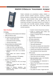
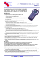
E1 TRANSMISSION ANALYZER
XG2125
This E1 service tester is a multi-functional digital transmission system
test device, designed for the installation test, engineering check and
acceptance, daily maintenance of the E1 PCM line (G.703 2Mbit/s),
mainly performing channel test, alarm analysis, fault finding and
signaling analysis of the E1 (2Mb/s) line. This instrument mainly has
following functions:
Basic Functions
¾ Support interface test of unbalanced 75Ω and balanced 120Ω.
¾ Support HDB3 and AMI line coding.
¾ Framed test under TX/RX mode (Out-of-service test).
√ Framed/unframed end-to-end 2Mb/s BER testing.
√ N×64Kb/s BER testing.
√ Can monitor signal loss , AIS, frame loss, remote alarm, remote multiframe alarm,
CRC multiframe loss, CAS multiframe loss, pattern loss alarm and bit, CODE, FAS,
E-BIT error and so on.
√ Clock slip measurement.
¾ Online BER monitoring and timeslot analysis under RX HI-Z (high
impedance) and through (bridge) mode.
√ Performance test of bit error, coding error, FAS error, CRC4 error and E bit error.
√ FAS and MFAS word analysis, timeslot busy or idle status display.
√ Timeslot content monitoring, monitoring and display of 8-bit digital code word in any selected timeslot.
√ Any 64kb/s tone channel monitoring.
√ CAS (channel associated signaling) ABCD code monitoring and CCS (common channel signaling) TS16 timeslot monitoring.
¾ Framed/unframed Round Trip Delay measurement.
¾ 2M or 64kb/s signal of SDH transmission network automatic protection switching (APS) delay measurement.
¾ PCM simulation mode:
√ Simulate PCM terminal to perform various error insertion and alarm insertion.
√ Transmit editable Si, Sa, A, FAS, CRC-4, MFAS, NMFAS and E- bit.
√ Insert idle codes into one or more timeslots, and the idle code pattern is programmable.
√ Insert single audio signals whose signal frequency and voltage are adjustable in one or more timeslots.
√ Monitor any voice channel in the receiving terminal, single audio channel can measure signal voltage and frequency at the same
time.
√ CAS (channel associated signaling) ABCD code programming, CCS (common channel signaling) TS16 content programmable;
¾ 2M signal level, frequency, offset measurement.
¾ Transmission clock maximum deviation ±999ppm, effectively assess the clock restoration capability of the tested
¾
¾
¾
¾
¾
¾
¾
circuit.
Transmission clock: internal, interface, external 2M clock/signal (optional).
Test code type pattern: pseudorandom binary sequence (PRBS), fixed code and 16BIT user programmable code.
Bit, rate and other types of error insertion modes.
Real time display open circuit and short circuit status of the transmission circuit, effectively identify cable fault.
Has automatic test function at fixed time.
Perform the error analysis according to the G.821, G.826 and M.2100 standard of ITU-T.
Use the TestManager software for measurement result analysis, clean up, archiving and print output on PC via the
serial port;
Main Features
¾ Handheld structure, durable design, suitable for carrying around and on-spot measurements.
¾ High resolution backlight LCD, smart navigation mode operation displays in English.
¾ Combine BERT, time-slot analysis, signalling testing, signal analysis, and other functions together.
¾ Synchronization performance measurements give references to the more and more important system
synchronization problem.
¾ Up to 99 days continuance test performance.
¾ High storages capacity, can store 4 groups of test results including settings and results information.
¾ Built-in NiMH rechargeable batteries and embedded with smart fast charger circuit. Can be charged with
automobile cigarette lighter battery adapter.
¾ Real-time clock and storages could be kept during a long time by power supply of the second spare
battery without AC adapter and built-in NiMH battery module.
¾ By using TestManager software, upgrading the embedded software of the instruments via the serial port
to perfect the functionalities of the instrument and protect your investment.
CNS Srl – www.cnssrl.it email: [email protected]
Via A.Manzoni 9 -20010 Pregnana Milanese – Tel 02 9329 0697 Fax 02 9329 0790
E1 TRANSMISSION ANALYZER
XG2125
Standard Configuration
Hardware
Qty.
Software
Qty.
XG2120 E1 Service Tester
1
Embedded Software
1
AC Power Adapter
1
TestManager Setup CD
1
Automobile Cigarette Lighter Battery
1
Others
75OHM Unbalanced Test Cable
2
Waterproof Package
1
120 OHM balanced Test Cable
1
User’s Manual
1
RS232 Communication Cable
1
Maintenance Card
1
AA NiMH Rechargeable Batteries
5
Quality Certificate Card
1
Packing List
1
Adapter Cable
Options
¾ G.703 CO Datacom Interface Testing
¾ Level Measurement
Specifications
Item
Description
internal Clock
2048Kb/s ± 10ppm
Tx Frequency deviation
±999ppm
Rx Rate
2048Kb/s±999ppm
75ohm, Unbalanced, 120ohm, balanced; High Input
Interfaces
Impedance >2KΩ
Line Code
HDB3,AMI
Frame Structure
Unframed , PCM30, PCM30CRC, PCM31, PCM31CRC
Input Sensitivity
0~-43dB
Rx Frequency offset
Accuracy: ±1Hz, range: -999ppm~+999ppm
Transmission clock source
Insert Audio Signal
Generated from inside, interface extract, external 2M clock/
signal (optional)
Frequency range: 200Hz~3400Hz
Voltage range: -60.00dB~+3.14dB
Receiving frequency range: 200Hz~3400Hz
Measurement frequency accuracy: ±1Hz
Single Audio Signal Test
Receiving voltage range: -60.00dB~+3.14dB
Measurement voltage accuracy:
-60.00dB~-21.00dB range: ±2.87dB
-20.00dB~+3.14dB range: ±0.21dB
CNS Srl – www.cnssrl.it email: [email protected]
Via A.Manzoni 9 -20010 Pregnana Milanese – Tel 02 9329 0697 Fax 02 9329 0790
E1 TRANSMISSION ANALYZER
XG2125
“E1” Specifications
General
Measuring interface
Alarm LEDs
E1 standards
Test Pattern
Test Period
Result Analysis
Transmitter
Line Code
Impedance
Pulse Shape
Jitter
Tx Clock Source
Internal Tx Clock
2048Kb/s
Signal Loss, AIS, Frame Loss, MFrame Loss (CAS and CRC)
Remote Alarm (RDI and Remote MF), Pattern Loss
Errors, Clock Slip
• Comply with G.703, G.706, G.732
• PCM30: G.704 with CAS multiframe
• PCM31: G.704 with no multiframe
• PCM30CRC: G.704 with CAS and CRC4 multiframe
• PCM31CRC: G.704 with CRC4 multiframe
• PRBS: 223-1(O.151), 215-1(O.151), 211-1(O.153), 29-1
• Fixed Code: 1111, 0000, 1010
• 16BIT: Fully programmable 16-bit word
• PRBS Polarity: “Normal” or “Inverted”
Manual, Auto, Timer
G.821, G.826, M.2100 Analysis
HDB3, AMI
75Ω unbalanced, 120Ω balanced
Conforms to ITU-T G.703 Table 6
Meets ITU-T G.823 Section 2
Internal, Interface, External source
• Frequency: 2.048 MHz
• Stability: ±10 ppm temperature 0~40℃
• Ageing: ±2 ppm per year (typical)
• Deviation: ±999 ppm
External Tx Clock 2.048 MHz ± 200 ppm binary clock or 2 Mbit/s HDB3 signal
Error Add
BIT, CODE, FAS, CRC4, E-BIT
Error Add Rate
Single, 1E-N, N=2~7
Receiver
Rate
Line Code
Pulse Shape
Jitter Tolerance
Impedance
2.048 Mbit/s ± 999 ppm (G.703 specs ±50 ppm)
HDB3, AMI
Conforms to ITU-T G.703 Table 6
Meets ITU-T G.823 Section 3
• “TX/RX”: 75Ω unbalanced, 120Ω balanced
• “RX HI-Z”: >2KΩ unbalanced, balanced
• “Through”: 75Ω unbalanced, 120Ω balanced
Receive Sensitivity > -43dB
External Clock Input
• Binary Clock Input: 2.048 MHz, Square ware, TTL
• 2M bit/s Signal Input: HDB3, 75Ω unbalanced
VF Tone Measurement
• Frequency Measurement: 200Hz ~ 3400Hz
• Frequency Accuracy: ± 1Hz
• Level Measurement: -60 dB ~ +3.14 dB
• Level Accuracy:
-60 dB ~ -21 dB: ± 2.87 dB
-20 dB ~+3.14 dB: ±0.21 dB
Delay Measurement Accuracy: ± 1 µs
CNS Srl – www.cnssrl.it email: [email protected]
Via A.Manzoni 9 -20010 Pregnana Milanese – Tel 02 9329 0697 Fax 02 9329 0790
E1 TRANSMISSION ANALYZER
XG2125
“Datacom” Specifications (Option)
General
V.24, V.35, V.36, X.21, RS-449, RS-485, EIA-530, EIA-530A
DTE or DCE
PRBS: 220-1(O.153), 215-1(O.151), 211-1(O.153), 29-1(O.153), 26-1
Fixed Code: 1111, 0000, 1010
16BIT: Fully programmable 16-bit word
PRBS Polarity: “Normal” or “Inverted”
G.821 Analysis
Measuring interface:
Terminal Emulation
Test Pattern
Result Analysis
Transmitter
¾ Synchronous Mode
General
Clock Source
Synthesizer Rates
Synthesizer Accuracy
Interface Clock Source
Clock Output
Provided for all datacom interfaces
Internal synthesizer
Datacom interface. May be inverted,
Allowing selectable clock/data phase relationship
X.21 operation limited as follows:
DTE: datacom interface
DCE: internal
1.2 Kb/s, 2.4 Kb/s, 4.8 Kb/s, 7.2 Kb/s, 9.6 Kb/s, 19.2 Kb/s, 38.4 Kb/s,
N×64 Kb/s (N=1~32)
±30 ppm
Ageing ±2 ppm per year typical
Minimum rate: 50 bit/s
Maximum rate: 2.048 Mb/s
Datacom interface. May be inverted, allowing selectable clock/data
phase relationship.
No clock output on X.21 interface when configured as DTE.
¾ Asynchronous Mode
Not provided for X.21 operation.
50 b/s, 75 b/s, 150 b/s, 300 b/s, 600 b/s, 1.2K b/s, 2.4 Kb/s, 4.8 Kb/s,
7.2 Kb/s, 9.6 Kb/s, 19.2 Kb/s.
· Character length: 5, 6, 7 or 8 bits.
· Parity: odd, even, 0, 1 or none.
· Stop bits: 1 or 2 (character length 6, 7 or 8 bits);
1.5 (character length 5 bits).
Normal or inverse polarity may be selected.
Same as “E1”. (Bit error only)
General
Rates
Character Format
Data Polarity
Error Add
Receiver
¾ Synchronous Mode
Rates
Clock Sources
Maximum rate 2.048 Mbit/s
Datacom interface.
Internal (DCE mode only).
Data is clocked coincident with the transmitter output clock.
Both sources may be inverted, allowing selectable clock/data phase
relationship.
X.21 operation limited as follows:
DTE: datacom interface.
DCE: internal.
¾ Asynchronous Mode
General
Rates
Character Format
Data Polarity
Not provided for X.21 operation.
As selected for transmitter.
As selected for transmitter.
Normal or inverse polarity may be selected.
CNS Srl – www.cnssrl.it email: [email protected]
Via A.Manzoni 9 -20010 Pregnana Milanese – Tel 02 9329 0697 Fax 02 9329 0790
E1 TRANSMISSION ANALYZER
XG2125
“G.703 CO” Specifications (Option)
General
Measuring Interface
Standard
Line Code
Test Pattern
Test Period
Result Analysis
Physical Interface
G.703 co-directional
G.703
AMI
Same as “E1”
Manual, Auto, Timer
G.821 Analysis
DB44 (G.703 CO test cable)
Transmitter
Impedance
Pulse Shape
Tx Clock Source
Internal Tx Clock
Octet Timing
Error Add
120 Ohm balanced (Nominal)
Conform to with ITU-T G.703 Table 1
Internal, Interface (Loop timing)
· Frequency: 64 kHz
· Stability: ± 30 ppm temperature 0~40
· Ageing: ±2 ppm per year (typical)
Comply with ITU-T G.703, can be disabled.
Same as “E1”
Receiver
Rate
Input Impedance
Pulse Shape
Interference
Jitter Tolerance
Alarm Detection
Serial Port
64 kbit/s ± 150 ppm
(G.703 specs ± 100 ppm)
120 Ohm balanced (Nominal)
Conforms to ITU-T G.703 Table 1
Typically meets G.703
Meets ITU-T G.823 Section 3
Signal Loss, Octet Loss
Other Specifications
RS-232
Baud Rate: 19.2 Kb/s
Character Length: 8 bit
Parity: None
Stop Bits: 1 bit
Battery
5×1.2V AA NiMH rechargeable battery, GP180AAHC, 1800 mAH
AC Power Adapter Input: AC 100V~240V ±10% 50/60 Hz 0.45A
Output: DC12V/1.5A
Dimension
249mm×90/128mm×60mm (L×W×H)
Weight
760g
Operating Temperature 0~40℃
Storage Temperature
-30~+70℃
Humidity
5%~90% no condensation
CNS Srl – www.cnssrl.it email: [email protected]
Via A.Manzoni 9 -20010 Pregnana Milanese – Tel 02 9329 0697 Fax 02 9329 0790