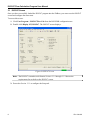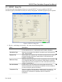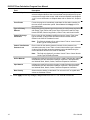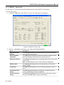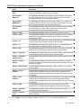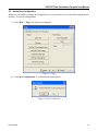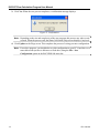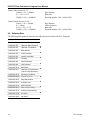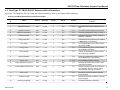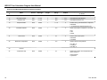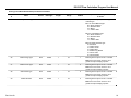
1
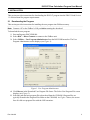
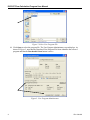
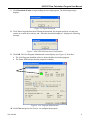
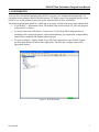
Remote Automation Solutions ISO5167 Flow Calculation Program (For the FloBoss 103) User Manual (QER 04Q017) Form A6160 November 2009 ISO5167 Flow Calculation Program User Manual Revision Tracking Sheet November 2009 This manual may be revised periodically to incorporate new or updated information. The revision date of each page appears at the bottom of the page opposite the page number. A change in revision date to any page also changes the date of the manual that appears on the front cover. Listed below is the revision date of each page (if applicable): Page All Pages All Pages Initial Issue Revision Nov-09 Oct-04 May-04 NOTICE “Remote Automation Solutions (“RAS”), division of Emerson Process Management shall not be liable for technical or editorial errors in this manual or omissions from this manual. RAS MAKES NO WARRANTIES, EXPRESSED OR IMPLIED, INCLUDING THE IMPLIED WARRANTIES OF MERCHANTABILITY AND FITNESS FOR A PARTICULAR PURPOSE WITH RESPECT TO THIS MANUAL AND, IN NO EVENT SHALL RAS BE LIABLE FOR ANY INCIDENTAL, PUNITIVE, SPECIAL OR CONSEQUENTIAL DAMAGES INCLUDING, BUT NOT LIMITED TO, LOSS OF PRODUCTION, LOSS OF PROFITS, LOSS OF REVENUE OR USE AND COSTS INCURRED INCLUDING WITHOUT LIMITATION FOR CAPITAL, FUEL AND POWER, AND CLAIMS OF THIRD PARTIES. Bristol, Inc., Bristol Canada, BBI SA de CV and Emerson Process Management Ltd, Remote Automation Solutions division (UK), are wholly owned subsidiaries of Emerson Electric Co. doing business as Remote Automation Solutions (“RAS”), a division of Emerson Process Management. FloBoss, ROCLINK, Bristol, Bristol Babcock, ControlWave, TeleFlow and Helicoid are trademarks of RAS. AMS, PlantWeb and the PlantWeb logo are marks of Emerson Electric Co. The Emerson logo is a trademark and service mark of the Emerson Electric Co. All other trademarks are property of their respective owners. The contents of this publication are presented for informational purposes only. While every effort has been made to ensure informational accuracy, they are not to be construed as warranties or guarantees, express or implied, regarding the products or services described herein or their use or applicability. RAS reserves the right to modify or improve the designs or specifications of such products at any time without notice. All sales are governed by RAS’ terms and conditions which are available upon request. RAS does not assume responsibility for the selection, use or maintenance of any product. Responsibility for proper selection, use and maintenance of any RAS product remains solely with the purchaser and end-user.” © 2004-2009 Remote Automation Solutions, division of Emerson Process Management. All rights reserved. ii Rev. Nov-09 ISO5167 Flow Calculation Program User Manual Contents Page 1 INTRODUCTION 1 1.1 SCOPE AND ORGANIZATION .....................................................................................................1 1.2 PRODUCT OVERVIEW...............................................................................................................1 1.3 PROGRAM REQUIREMENTS ......................................................................................................2 2 INSTALLATION 3 2.1 DOWNLOADING THE PROGRAM .................................................................................................3 3 CONFIGURATION 7 3.1 ISO5167 SCREEN ...................................................................................................................8 3.1.1 ISO5167 – SETUP TAB ................................................................................................9 3.1.2 ISO5167 – VALUES TAB ............................................................................................11 3.2 SAVING THE CONFIGURATION .................................................................................................13 4 REFERENCE 15 4.1 ISO5167 FLOW TASK LIMITS OF USE .....................................................................................15 4.2 SOFTPOINT DATA ..................................................................................................................16 4.3 POINT TYPE 22: FB103 ISO5167 SETUP AND VALUES PARAMETERS ......................................17 Rev. Nov-09 iii ISO5167 Flow Calculation Program User Manual [This page is intentionally left blank.] iv Rev. Nov-09 ISO5167 Flow Calculation Program User Manual 1 INTRODUCTION 1.1 Scope and Organization This document serves as the user manual for the ISO5167 Flow Calculation Program (QER 04Q017), which is intended for use in a FloBoss™ 103 (FB103). This manual describes how to download and configure this program (referred to as the “ISO5167 program” or “the program” throughout the rest of this manual). You access and configure this program using ROCLINK™ 800 Configuration Software (version 1.83 or greater) loaded on a personal computer (PC) running Windows® 2000 (with Service Pack 2), Windows XP, or Windows Vista. The sections in this manual provide information in a sequence appropriate for first-time users. Once you become familiar with the procedures and the software running in a FB103, the manual becomes a reference tool. This manual has the following major sections: Section 1 – Introduction Section 2 – Installation Section 3 – Configuration Section 4 – Reference This manual assumes that you are familiar with the FB103 and its configuration. For more information, refer to the following manuals: FloBoss 103 and 104 Flow Manager Instruction Manual (Form A6114) ROCLINK 800 Configuration Software User Manual (Form A6121) 1.2 Product Overview The ISO5167 program allows a FB103 to calculate an instantaneous flow rate for orifice, nozzle and venturi installations. The program calculates flowing density, gas expansion factor and coefficient of discharge for current flowing conditions to be used in the instantaneous flow rate calculation. Instantaneous rates are corrected to base conditions and provided in CF/HR (M3/HR) and MCF/DAY (kM3/DAY). The flow calculations are based on Standards ISO5167-1991, ISO5167-1998 and ISO5167-2003. The program provides flow rates, integrate volumes, and archive historical values for installations implementing an orifice with corner, flange or D/D2 taps, an ISA1932 or long radius nozzle, a venturi tube or nozzle. It has calculations for the 1991, 1998 and 2003 editions of the ISO Standard. Gas compressibility calculations are implemented using FloBoss firmware and AGA8 1992 standards or installed properties user program. The standard AGA3 flow rate calculation is replaced by the ISO5167 instantaneous rate calculation performed by the user program. The composition ranges and fluids that the program is designed for are natural gas and other related hydrocarbons as defined in AGA Report #8, 1992 editions. Alternatively, the program can be run with a second User Program to replace the AGA8 firmware to calculate the gas properties. The FloBoss 103 reads flow inputs (differential pressure, static pressure, and temperature) once every second. Also, it performs an AGA8 1992 calculations (including compressibility values, gas constants and base density values), accumulates volumes, and integrates the volumes into the historical archive at a user-configured scan period. The ISO5167 instantaneous flow calculation is performed once a second. Configuration is accomplished through the standard meter run configuration display and ISO5167 user display. Rev. Nov-09 1 ISO5167 Flow Calculation Program User Manual 1.3 Program Requirements You download the ISO5167 program to—and then run it from—the Flash and RAM memory on the FloBoss 103 with firmware version 2.14 (or greater). Download and configure the program using the ROCLINK 800 Configuration software version 1.83 (or greater). The downloadable program is: File Name ISO5167.bin Unit FloBoss 103 Task UserCalc1 Code Space 790000-79FFFF Data Space 46C000-46CFFF UDP 22 Note: You must connect a PC to the FloBoss’s LOI port before starting the download. For information on viewing the memory allocation of user programs, refer to the ROCLINK 800 Configuration Software User Manual (Form A6121). 2 Rev. Nov-09 ISO5167 Flow Calculation Program User Manual 2 INSTALLATION This section provides instructions for downloading the ISO5167 program into the FB103. Read Section 1.3 of this manual for program requirements. 2.1 Downloading the Program This section provides instructions for installing the user program into FloBoss memory. Note: Connect a PC to the FloBoss’s LOI port before starting the download. To download the user program: 1. Start and logon to ROCLINK 800. 2. Select ROC > Direct Connect to connect to the FloBoss unit. 3. Select Utilities > User Program Administrator from the ROCLINK menu bar. The User Program Administrator screen displays (see Figure 1): Figure 1. User Program Administrator 4. Click Browse in the Download User Program File frame. The Select User Program File screen displays (see Figure 2). 5. Select the path and user program file to download from the CD-ROM. (Program files are typically located in the Program Files folder on the CD-ROM). As Figure 2 shows, the screen lists all valid user program files with the .BIN extension: Rev. Nov-09 3 ISO5167 Flow Calculation Program User Manual Figure 2. Select User Program File 6. Click Open to select the program file. The User Program Administrator screen displays. As shown in Figure 3, note that the Download User Program File frame identifies the selected program and that the Download & Start button is active: Figure 3. User Program Administrator 4 Rev. Nov-09 ISO5167 Flow Calculation Program User Manual 7. Click Download & Start to begin loading the selected programs. The following message displays: Figure 4. Confirm Download 8. Click Yes to begin the download. During the download, the program performs a warm start, creates an event in the event log, and—when the download completes—displays the following message: Figure 5. ROCLINK 800 Download Confirmation 9. Click OK. The User Program Administrator screen displays (see Figure 6). Note that: The User Programs Installed in Device frame identifies the loaded program. The Status field indicates that the program is running. Figure 6. User Program Administrator 10. Click Close and proceed to Section 3 to configure the program. Rev. Nov-09 5 ISO5167 Flow Calculation Program User Manual [This page is intentionally left blank.] 6 Rev. Nov-09 ISO5167 Flow Calculation Program User Manual 3 CONFIGURATION After you have downloaded and started the ISO5167 program, you configure the program and view calculation results using the ROCLINK 800 software. To do this, you use one program-specific screen (ISO5167) to set the parameters and view results from the ISO5167 flow calculations. The following parameters should be verified and, if necessary, altered in the meter setup configuration: Go to the ROC > Information screen. The default Units selected will be US. The user program will permit US or Metric. Go to the General tab of the Meter > Setup screen. Verify all the Meter Setup parameters (including orifice and pipe diameters, input point definitions, gas composition, compressibility method, base conditions and absolute/gauge tap type). Go to the Configure > History Points screen. The first eight points are pre-defined. Typical gas flow applications will utilize these eight points. The user may configure others if the application requires. Figure 7. ROCLINK 800 Rev. Nov-09 7 ISO5167 Flow Calculation Program User Manual 3.1 ISO5167 Screen Once you have successfully loaded the ISO5167 program into the FloBoss, you can access the ISO5167 screen and configure the meter runs. To access this screen: 1. Click User Program > ISO5167 Flow Calc from the ROCLINK configuration tree: 2. Double-click Display #23, ISO5167. The ISO5167 screen displays: Figure 8. ISO5167 Screen Note: The ISO5167 screen has a tab format. Sections 3.1.1 through 3.1.2 discuss the requirements for each tab on the ISO5167 screen. 3. Proceed to Section 3.1.1 to configure the Setup tab. 8 Rev. Nov-09 ISO5167 Flow Calculation Program User Manual 3.1.1 ISO5167 – Setup Tab Use the Setup tab (which displays when you access the ISO5167 screen) to enable the ISO5167 calculation, specify calculation revision year used by the program, and define program-specific options. Figure 9. ISO5167, Setup Tab 1. Review—and change as necessary—the values in the following fields: Field Description Run Status Enables or disables the ISO5167 program to perform the flow calculations for the selected meter run. Valid selections are Enabled or Disabled. Calculation Type Select the revision date of the ISO5167 calculation used. Valid values are 1991, 1998, and 2003. Pressure Tap Select location of the pressure tap. This field must match how the sensor or transmitter actually measures the static pressure. Valid selections are Upstream or Downstream. Reference Temp Select the reference temperature and the corresponding value for density of air (ISO6976-1998) used in the calculation of base density and flowing density when there is not a properties user task. Valid values are 0 Deg. C, 15 Deg. C, and 20 Deg. C. Use Limit Checks Enables limits of the use checks on the process data defined for the ISO5167 calculations. If the checks are not satisfied, an alarm condition is met and the program stops the calculation. Temperature Tap Select the location of the temperature measurement for the meter run. Valid values are Upstream and Downstream. If downstream is selected, the temperature is corrected to an upstream value for the ISO5167 calculations. Rev. Nov-09 9 ISO5167 Flow Calculation Program User Manual Field Description Save to Softpoints Click ▼ to select a softpoint to use when storing calculated data. The selected softpoint allows a host to access data from the softpoint if they can not access it through other means. Valid values are Disabled, and Softpoint 1-16. For more information on Softpoint data, refer to Section 4.2, Softpoint Data. Force Recalc Forces the program to immediately recalculate the flow without waiting for the next normal recalculation period. Select Set and click Apply to force the recalculation. Type of Primary Element Selects the primary element type for the meter run. Valid values are Orifice with Flange Type, Orifice with Corner Taps, Orifice with D and D/2 Taps, Nozzle ISA7932, Nozzle Long Radius, Venturi Tube, and Venturi Nozzle. Venturi Discharge Coefficient Enter a value for the discharge coefficient when the Venturi Tube meter type is selected. A value of 0 in this field means the default value as defined in the ISO5167 Standard is used. Note: This field only displays if you select Venturi Tube or Venturi Nozzle as the Type of Primary Element. Venturi Tube Relative Pressure Loss Enter a value for the relative pressure loss ratio for the pressure loss calculation when the Venturi Tube or Venturi Nozzle meter type is selected. A value of 0 in this field means the pressure loss is calculated using the orifice calculation defined in the ISO5167 Standard. Note: This field only displays if you select Venturi Tube or Venturi Nozzle as the Type of Primary Element. Orifice Material Indicates the material from which the orifice is made. Selecting the material automatically sets the associated expansion coefficient. Valid selections are Stainless Steel, Monel, Carbon, and Enter Expansion Coefficient. Pipe Material Indicates the material from which the pipe is made. Selecting the material automatically sets the associated expansion coefficient. Valid selections are Stainless Steel, Monel, Carbon, and Enter Expansion Coefficient Base Density Selects how the density is calculated. The units are Lb/CF or Kg/M3.Valid values are Calculate or Enter. 2. Click Apply to save any changes, and proceed to Section 3.1.2 to view the Values tab. 10 Rev. Nov-09 ISO5167 Flow Calculation Program User Manual 3.1.2 ISO5167 – Values Tab Use this screen to view the results and calculation factors used in ISO5167 calculations. To access this screen: 1. Select the Values tab on the ISO5167 screen. The following screen displays: Figure 10. ISO5167, Values Tab 2. Review—and change as necessary—the values in the following fields: Field Description Program Title and Revision This read-only field displays the name and revision level of the ISO5167 Flow Calculation user program. Active Properties Calculation This read-only field displays the properties calculation standard currently performing properties calculations for the selected meter run. Differential Pressure This read-only field displays the current differential pressure. The units are InH2O or kPa. Note: This field displays only if the meter’s input type is differential. Static Pressure This read-only field displays the current static pressure in PSIG, PSIA, kPa(g) or kPa(a). Temperature This read-only field displays the current flowing temperature in Deg F or Deg C. Current Flow Rate – Volume This read-only field displays the current hourly and daily flow rates in CF/Hour and MCF/Day or M3/hr and kM3/Day. Current Flow Rate – Energy This read-only field displays the current hourly and daily energy rates in BTU/Hour and MMBTU/Day or MJ/Hour and GJ/Day. Rev. Nov-09 11 ISO5167 Flow Calculation Program User Manual Field Description Current Flow Rate – Mass This read-only field displays the current hourly and daily mass rates in Lb/Hour and Mlb/Day or Kg/Hour and Tonnes/Day. Accumulation – MCF/km3 This read-only field displays the total flow in MCF or kM3 for the current day, the previous day, the current month, the previous month, and the accumulated total since the accumulator last reset. Accumulation – MMBTU/GJ This read-only field displays the total energy in MMBTU or GJoules for the current day, the previous day, the current month, the previous month, and the accumulated total since the accumulator last reset. Accumulation – Minutes This read-only field displays the flowing time in Minutes for the current day, the previous day, the current month, the previous month, and the accumulated total since the accumulator last reset. Factors – hwPf This read-only field displays pressure extension in SQRT of HW * PF. Factors – CdFT This read-only field displays the coefficient of discharge (CdFT), calculated based on the average flowing conditions during the previous integral multiplier period (IMP). Factors – Ev This read-only field displays the velocity of approach (Ev), calculated based on the average flowing conditions during the previous IMP. Factors – Y This read-only field displays the expansion factor (Y), calculated based on the average flowing conditions during the previous IMP. Factors – IMV This read-only field displays the integral multiplier value (IMV), calculated based on the average flowing conditions during the previous IMP. Factors – Reynolds This read-only field displays the Reynolds number (ReD), calculated based on the average flowing conditions during the previous IMP. Factors – Upstream Static Pressure This read-only field displays the upstream absolute static pressure in PSIA or kPa(A). Factors – Flowing Density This read-only field displays the density at flowing conditions, calculated based on the average flowing conditions during the previous IMP. The units are Lb/CF or Kg/M3. Factors – Base Density This read-only field displays the density at base conditions. The units are Lb/CF or Kg/M3. Factors – Orifice Diameter This read-only field displays the actual orifice plate bore diameter at flowing conditions as calculated based on the specified orifice diameter and the average flowing temperature during the previous IMP. The units are inches or millimeters. Factors – Pipe Diameter This read-only field displays the actual inside diameter of the pipe at flowing conditions as calculated based on the specified pipe diameter and the averaging flowing temperature during the previous IMP. The units are inches or millimeters. Factors – Beta This read-only field displays the ratio of the orifice or nozzle to pipe diameters at the average flowing temperature during the previous IMP. Factors – Upstream Temperature This read-only field displays the live flowing temperature reading in °F or °C, converted to upstream conditions. Factors – Pressure Loss This read-only field displays the calculated Pressure Loss for the current flowing conditions. 3. Click Apply to save any changes, and proceed to Section 3.2 to save the configuration. 12 Rev. Nov-09 ISO5167 Flow Calculation Program User Manual 3.2 Saving the Configuration Whenever you modify or change the configuration, it is a good practice to save the final configuration to memory. To save the configuration: 1. Select ROC > Flags. The Flags screen displays: Figure 11. Flags 2. Click Save Configuration. A verification message displays: Figure 12. Save Verification Rev. Nov-09 13 ISO5167 Flow Calculation Program User Manual 3. Click Yes. When the save process completes, a confirmation message displays: Figure 13. Confirmation Note: Depending on the size and complexity of the user program, this process may take several seconds. When the process ends, the Status field on the Flags screen displays Completed. 4. Click Update on the Flags screen. This completes the process of saving your new configuration. Note: For archive purposes, you should also save this configuration to your PC’s hard drive or a removable media (such as a diskette or a flash drive) using the File > Save Configuration option on the ROCLINK 800 menu bar. 14 Rev. Nov-09 ISO5167 Flow Calculation Program User Manual 4 REFERENCE This section provides the reference for the calculations and tables of parameters for the user-defined points used by the ISO5167 Flow Calculation program. ISO5167 Flow Tasks Limits of Use Softpoint Data Point Type 22: FB103 ISO5167 Setup and Values Parameters 4.1 ISO5167 Flow Task Limits of Use The calculations are valid for the following conditions. Checks can be enabled by setting the LimCheck flag on the ISO5167 screen. Corner and D-D/2 taps Section 8.3.1: d >= 12.5mm 50mm <= D <= 1000mm 0.1 <= B <= 0.75 Re > 5000 for 0.2 <= B <= 0.45 Re > 10000 for B > 0.45 Re > 4000 for 0.1 <= B <= 0.5 Re > 16000 B * B for B > 0.5 Re > 5000 for 0.1 <= B <= 0.56 Re > 16000 B * B for B > 0.56 Flange taps Section 8.3.1: d >= 12.5mm 50mm <= D <= 1000mm 0.1 <= B <= 0.75 Re >= 1260 B * B * D Re >= 4000 Re >= 170 B * B * D Re >=5000 Re >= 170 B * B * D Orifice diameter Pipe diameter Beta ratio Reynolds number 1991 Reynolds number 1998 Reynolds number 2003 Orifice diameter Pipe diameter Beta ratio Reynolds number 1991 Reynolds number 1998 Reynolds number 2003 ISA 1932 Nozzles Section 9.1.6: 50mm <= D <= 500mm Pipe diameter 0.3 <= B <= 0.8 Beta ratio 70000 <= Re <= 107 for 0.3 <= B <= 0.44 Reynolds number 7 1991, 1998 & 2003 20000 <= Re <= 10 for 0.44 <= B <= 0.8 Long radius Nozzles Section 9.2.6: 50mm <= D <= 630mm 0.2 <= B <= 0.8 10000 <= Re <= 107 Rev. Nov-09 Pipe diameter Beta ratio Reynolds number 1991, 1998 & 2003 15 ISO5167 Flow Calculation Program User Manual Venturi Tube Section 10.1.5: 100mm <= D <= 800mm 0.3 <= B <= 0.75 200000 <= Re <= 2000000 Pipe diameter Beta ratio Reynolds number 1991, 1998 & 2003 Venturi Nozzle Section 10.2.4: 65mm <= D <= 500mm d >= 50mm 0.316 <= B <= 0.775 150000 <= Re <= 2000000 Pipe diameter Orifice diameter Beta ratio Reynolds number 1991, 1998 & 2003 4.2 Softpoint Data The following data points are stored to the softpoint selected on the ISO5167, Setup tab. Softpoint Data Data Point # 1 Differential Pressure Data Point # 2 Upstream Static Pressure Data Point # 3 Upstream Temperature Data Point # 4 Base Density Data Point # 5 Flowing Density Data Point # 6 Specific Heat Ratio Data Point # 7 Viscosity Data Point # 8 Orifice Diameter Data Point # 9 Pipe Diameter Data Point # 10 Beta Ratio Data Point # 11 Upstream Temp Exponent (calc from Sp Heat Ratio) Data Point # 12 Discharge Coefficient Data Point # 13 Expansion Factor Data Point # 14 Reynolds Number Data Point # 15 Pressure Loss Data Point # 16 Mass Flowrate Data Point # 17 Base Compressibility Data Point # 18 Flowing Compressibility Data Point # 19 Not Used Data Point # 20 Not Used 16 Rev. Nov-09 ISO5167 Flow Calculation Program User Manual 4.3 Point Type 22: FB103 ISO5167 Setup and Values Parameters Point type 22 contains the ISO5167 setup and values parameters. There is one logical of this point type. Point Type 22: FB103 ISO5167 Setup and Values Parameters Parm # Name Access Data Type Length Range Default 0 Flow Calculation Enable R/W UINT8 1 0 or 1 1 1 Differential Pressure R/O FLOAT 4 N/A 0.0 Live differential pressure reading in H2O or kPa. 2 Upstream Pressure R/O FLOAT 4 N/A 0.0 Live static pressure reading in PSIA or kPa. 3 Upstream Temperature R/O FLOAT 4 N/A 0.0 Live flowing temperature in Deg. C or Deg. F. 4 Volume Flow Rate R/O FLOAT 4 N/A 0.0 Instantaneous flow rate at base conditions in MCF/Day or kM3/Day. 5 Energy Flow Rate R/O FLOAT 4 N/A 0.0 Instantaneous energy rate at base conditions in MMBTU/Day or GJoules/Day. 6 Flow Today R/O FLOAT 4 N/A 0.0 Accumulated volume in the current contract day in MCF or kM3. 7 Energy Today R/O FLOAT 4 N/A 0.0 Accumulated energy in the current contract day in MMBTU or GJoules. 8 Flow Yesterday R/O FLOAT 4 N/A 0.0 Volume accumulated the previous contract day in MCF/Day or kM3/Day. 9 Energy Yesterday R/O FLOAT 4 N/A 0.0 Energy accumulated the previous contract day in MMBTU/Day or GJoules/Day. 10 Sample Time R/O FLOAT 4 N/A 0.0 Flow calculation period in seconds 11 Venturi Discharge Coefficient R/W FLOAT 4 N/A 0.0 Discharge Coefficient when a Venturi Tube meter type is selected. 12 Venturi Relative Pressure Loss R/W FLOAT 4 N/A 0.0 Relative pressure loss ratio for the pressure loss calculation when the venture Tube or Venturi Nozzle meter type is selected. 13 Base Density R/W FLOAT 4 N/A 0.0 Gas density as base conditions. Units are lbm/ft3 or kg/m3. 14 Upstream Density R/O FLOAT 4 N/A 0.0 Gas density at flowing conditions. . Units are lbm/ft3 or kg/m3. 15 Discharge Coefficient R/O FLOAT 4 N/A 0.0 Calculated coefficient of discharge. Rev. Nov-09 Description of functionality and meaning of values Enables ISO5167 Flow Calculations. 17 ISO5167 Flow Calculation Program User Manual Point Type 22: FB103 ISO5167 Setup and Values Parameters Parm # Name Access Data Type Length Range Default 16 Expansion Factor R/O FLOAT 4 N/A 0.0 Calculated expansion factor of discharge. 17 Reynolds Number R/O FLOAT 4 N/A 0.0 Calculated Reynolds Number. 18 Pressure Loss R/O FLOAT 4 N/A 0.0 Calculated Pressure Loss. 19 Softpoint Enable R/W UINT8 1 0 - 16 0 Description of functionality and meaning of values Enables saving calculated data to softpoints. 0=disabled. 1-16 indicates the softpoint logical to use. 20 Calculation Method R/W UINT8 1 0-2 2 Select which edition of ISO5167 to be used. 0=91. 1=98. 2=2003 21 Limit Checks R/W UINT8 1 0-1 0 Perform limit checks option. 0=disabled. 1=enabled. 22 Reference Temperature R/W UINT8 1 0-2 0 Selects reference temperature. 0=15 Deg. C. 1=0 Deg. C. 2=20 Deg. C. 23 Unused 24 Temperature Tap R/W UINT8 1 0-1 0 Selects the location of the temperature tap for the meter run. 0=downstream. 1=upstream. 18 Rev. Nov-09 ISO5167 Flow Calculation Program User Manual Point Type 22: FB103 ISO5167 Setup and Values Parameters Parm # Name Access Data Type Length Range Default 25 Primary Element Type R/W UINT8 1 N/A 0x71 Description of functionality and meaning of values Primary Element option, orifice and pipe material type: Bits 7-6: Orifice Material type: 00 = Enter coefficient 01 = Stainless Steel 10 = Monel 11 = Carbon Steel Bits 5-4: Pipe Material type: 00 = Enter coefficient 01 = Stainless Steel 10 = Monel 11 = Carbon Steel Bits3-0: Primary Element type: 0 = Not Used 1 = Orifice Flange 2 = Orifice Corner 3 = Orifice D/D2 4 = Nozzle Long Radius 5 = Venturi Tube 6 = Venturi Nozzle 26 Orifice Flange Type R/W UINT8 1 0-1 1 Metering device option. Set to 1 to enable. Note: this is not used in version 1.05 or greater except for display purposes. 27 Orifice Corner Type R/W UINT8 1 0-1 0 Metering device option. Set to 1 to enable. Note: this is not used in version 1.05 or greater except for display purposes. 28 Orifice D/D2 Type R/W UINT8 1 0-1 0 Metering device option. Set to 1 to enable. Note: this is not used in version 1.05 or greater except for display purposes. 29 Nozzle ISA1932 R/W UINT8 1 0-1 0 Metering device option. Set to 1 to enable. Note: this is not used in version 1.05 or greater except for display purposes. Rev. Nov-09 19 ISO5167 Flow Calculation Program User Manual Point Type 22: FB103 ISO5167 Setup and Values Parameters Parm # Name Access Data Type Length Range Default 30 Nozzle Long Radius R/W UINT8 1 0-1 0 Description of functionality and meaning of values Metering device option. Set to 1 to enable. Note: this is not used in version 1.05 or greater except for display purposes. 31 Venturi Tube R/W UINT8 1 0-1 0 Metering device option. Set to 1 to enable. Note: this is not used in version 1.05 or greater except for display purposes. 32 Venturi Nozzle R/W UINT8 1 0-1 0 Metering device option. Set to 1 to enable. Note: this is not used in version 1.05 or greater except for display purposes. 33 Enter Density R/W UINT8 1 0-1 0 Option to allow the user to enter the flowing density. 0=calculate. 1=manual. 20 34 Pipe Expansion Coefficient R/W FLOAT 4 N/A 0.0 Used to correct the pipe diameter for temperature effects. 35 Orifice Expansion Coefficient R/W FLOAT 4 N/A 0.0 Used to correct the orifice diameter for temperature effects. 36 Mass Flowrate R/O FLOAT 4 N/A 0.0 Flow rate in Mass. Units are kg/s. 37 Properties Calc R/O AC 20 N/A “” This string indicates the active properties program. 38 Unused 1 R/W UINT8 1 N/A 0 Unused. 39 Unused 2 R/W UINT8 1 N/A 0 Unused. 40 Force Recalc R/W UINT8 1 0-1 0 Forces the properties program to immediately re-calculate meter factors. 1=force. 41 Mass Flow Hour R/O FLOAT 4 N/A 0.0 Flow rate in Mass. Units are lb/hour or kg/hour 42 Mass Flow Day R/O FLOAT 4 N/A 0.0 Flow rate in Mass. Units are mlbs/day or tonnes/day. 43 Program Title R/O AC 40 N/A “” ISO5167 title and revision string. Rev. Nov-09 ISO5167 Flow Calculation Program User Manual [This page is intentionally left blank.] Rev. Nov-09 21 ISO5167 Flow Calculation Program User Manual If you have comments or questions regarding this manual, please direct them to your local sales representative or contact: Emerson Process Management Remote Automation Solutions Marshalltown, Iowa 50158 USA Houston, TX 77065 USA Pickering, North Yorkshire UK Y018 7JA Website: www.EmersonProcess.com/Remote