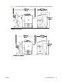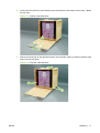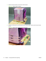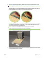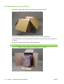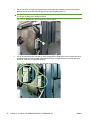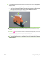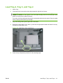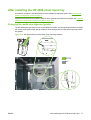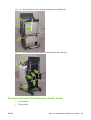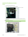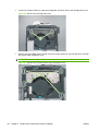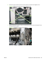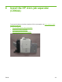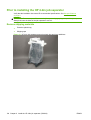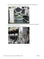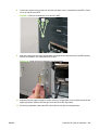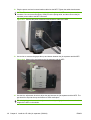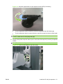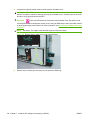
1
HP CM8060/CM8050 Color MFP
with Edgeline Technology
Install Guide
Syst
strat
HP CM8060/CM8050 Color MFP with Edgeline
Technology
Install Guide
Copyright and License
Safety information
Trademarks
© 2009 Copyright Hewlett-Packard
Development Company, L.P.
Potential Shock Hazard. Always follow basic
safety precautions when using the MFP to
reduce risk of injury from fire or electric
shock. Do not touch the contacts on the end
of any of the sockets on the MFP. Replace
damaged cords immediately. Use only a
grounded electrical outlet when connecting
the MFP to a power source. If you do not
know whether the outlet is grounded, check
with a qualified electrician.
All products mentioned herein may be
trademarks of their respective companies.
Reproduction, adaptation, or translation
without prior written permission is prohibited,
except as allowed under the copyright laws.
The information contained herein is subject
to change without notice.
The only warranties for HP products and
services are set forth in the express warranty
statements accompanying such products
and services. Nothing herein should be
construed as constituting an additional
warranty. HP shall not be liable for technical
or editorial errors or omissions contained
herein.
Edition 5.0, 2/2009
The power cord provides grounding for the
MFP and the accessories. To avoid
electrostatic buildup when connecting the
accessories to the MFP during installation,
make sure that the power cord is plugged into
the MFP and a grounded electrical
receptacle. If the power cord is unavailable,
you must use a suitable auxiliary ground
connection from the MFP chassis to a ground
source to protect the MFP and accessories
from electrostatic discharge (ESD) damage.
When the device is connected to a 110-127V
or 120V source, it must be connected to a
dedicated 20 Amp outlet.
AC Delta and AC Wye power system
statement: The MFP is designed to use an IT
power system.
Install the MFP on a stable surface. Install the
MFP in a protected location where no one
can step on or trip over the power cord and
where the power cord will not be damaged.
If the MFP does not operate normally, see
the service manual. Observe all warnings
and instructions marked on the MFP.
Always use the Fax line cord that is supplied
with the MFP. If you must use a replacement
line cord, make sure that it is a 26 AWG
telecommunications line cord.
WARNING! Risk of injury from moving parts.
Do not reach into stapler. Do not reach below
moving trays.
Document history
Version
Date
Content changes
1.0
01/2007
N/A
1.1
02/2007
Content changes reflect software and
hardware updates.
1.2
03/2007
Content changes reflect software and
hardware updates.
1.3
04/2007
Content changes reflect software and
hardware updates.
1.4
05/2007
Content changes reflect software and
hardware updates and additions
including but not limited to:
●
HP 4-bin job separator (C5964A)
◦
Unpacking
◦
Installation
●
System, operator, and service
dimension requirements
●
CDFT-E install configuration
◦
3.0
3.1
11/2007
12/2007
●
Pen packaging
●
SVC Kit-Reship, 4-Bin Job
Separator (C5964-67035)
Content changes reflect software and
hardware updates and additions
including but not limited to:
●
Environmental and electrical
specifications
●
Shipping kits
●
Space requirements
●
Engine calibrations
●
Acclimation information
●
Long grain media updates
Content changes reflect software and
hardware updates and additions
including but not limited to:
●
ENWW
Power setting (200-240V AC
systems only)
Space requirements
iii
Version
Date
Content changes
4.0
03/2008
Content changes reflect software and
hardware updates and additions
including but not limited to:
●
5.0
02/2009
Content changes reflect software and
hardware updates and additions
including but not limited to:
●
iv
Document history
Space requirements
Removed references to "Media
Gloss"
ENWW
Table of contents
1 Site preparation and unpacking
Before you begin .................................................................................................................................. 2
Tools used in this guide ....................................................................................................... 2
Electrostatic discharge connectors ...................................................................................... 3
Recycle ................................................................................................................................................. 5
Handling and disposing of service parts and consumables ................................................. 5
Site specifications ................................................................................................................................. 6
Weight and size specifications ............................................................................................. 6
System configuration dimensions ........................................................................................ 8
Operator space requirements ............................................................................................ 11
Service space requirements .............................................................................................. 12
Environmental and electrical specifications ....................................................................... 13
Unpacking .......................................................................................................................................... 14
Guidelines .......................................................................................................................... 14
Recommended tools (unpacking) ...................................................................................... 14
Unpack space requirements .............................................................................................. 15
HP CM8050/8060 MFP (C5958A/5957A) .......................................................................... 16
HP 4000-sheet input tray (C5961A) ................................................................................... 20
HP multifunction finisher (C5959A) .................................................................................... 21
HP 4-bin job separator (C5964A) ...................................................................................... 24
Narrow passageway .......................................................................................................... 27
2 Install the HP CM8050/8060 MFP (C5958A/5957A)
Prior to installing the HP CM8050/8060 MFP ..................................................................................... 34
Remove shipping materials ............................................................................................... 35
Recommended tools (HP CM8050/8060 MFP install) ....................................................... 36
Required installation components ...................................................................................... 36
Acclimate the system ......................................................................................................................... 37
Printhead and ink cartridge acclimation ............................................................................. 37
MFP acclimation ................................................................................................................ 37
Accessory acclimation ....................................................................................................... 37
Power cable ........................................................................................................................................ 38
ADF .................................................................................................................................................... 40
Scanner lock ....................................................................................................................................... 44
ENWW
v
Control-panel overlay ......................................................................................................................... 45
Ink cartridges ...................................................................................................................................... 46
Pens (printheads) ............................................................................................................................... 48
Pen care ............................................................................................................................ 48
Pen installation .................................................................................................................. 51
Load Tray 2, Tray 3, and Tray 4 ......................................................................................................... 61
After installing the HP CM8050/8060 MFP ......................................................................................... 62
3 Install the HP 4000-sheet input tray (C5961A)
Prior to installing the HP 4000-sheet input tray .................................................................................. 64
Remove shipping materials ............................................................................................... 64
Check elevator cables ....................................................................................................... 64
Recommended tools (HP 4000-sheet input tray install) .................................................... 64
Required installation components ...................................................................................... 64
Install HP 4000-sheet input tray ......................................................................................................... 65
After installing the HP 4000-sheet input tray ...................................................................................... 71
Changing the media size alignment guides ....................................................................... 71
4 Install the HP single output bin (C5963A)
Prior to installing the HP single output bin .......................................................................................... 76
Recommended tools (HP single output bin install) ............................................................ 76
Required installation components ...................................................................................... 76
Install the HP optional single output bin ............................................................................................. 77
After installing the standard output bin ............................................................................................... 82
5 Install the HP multifunction finisher (C5959A)
Prior to installing the HP multifunction finisher ................................................................................... 84
Remove shipping materials ............................................................................................... 84
Recommended tools (HP multifunction finisher install) ..................................................... 85
Required installation components ...................................................................................... 86
Install the HP multifunction finisher .................................................................................................... 87
Finisher .............................................................................................................................. 87
After installing the HP multifunction finisher ....................................................................................... 98
Change the stapler position ............................................................................................... 99
6 Install the HP 4-bin job separator (C5964A)
Prior to installing the HP 4-bin job separator .................................................................................... 104
Remove shipping materials ............................................................................................. 104
Recommended tools (HP 4-bin job separator install) ...................................................... 105
Required installation components .................................................................................... 105
Install the HP 4-bin job separator ..................................................................................................... 106
Job separator ................................................................................................................... 106
After installing the HP 4-bin job separator ........................................................................................ 113
vi
ENWW
7 Install the HP analog fax accessory (C5954A)
Prior to installing the HP analog fax accessory ................................................................................ 116
Recommended tools (HP analog fax accessory install) .................................................. 116
Required installation components .................................................................................... 116
Install the HP analog fax accessory ................................................................................................. 117
After installing the HP analog fax accessory .................................................................................... 121
8 Power-on calibrations, adjustments, settings, and tests
HP CM8050/8060 MFP .................................................................................................................... 124
Power on .......................................................................................................................... 125
Prevent startup calibrations ............................................................................................. 125
Set the control-panel display language ............................................................................ 126
Set the time zone, time, and date .................................................................................... 127
Scheduled calibration time ............................................................................................... 127
Set tray media type .......................................................................................................... 127
Set long-grain paper ........................................................................................................ 129
Configure the MFP for HP ink cartridges ......................................................................... 130
CDFT install configurations .............................................................................................. 130
EWS and AutoSend configuration .................................................................................................... 148
Configure and test the optional HP analog fax accessory ................................................................ 151
Configure the HP CM8050/8060 MFP fax function .......................................................... 151
Test the HP CM8050/8060 MFP fax function .................................................................. 151
Print a maintenance log .................................................................................................................... 152
Customer walkaround checklist ........................................................................................................ 153
9 Moving the HP CM8050/8060 MFP
Before you begin .............................................................................................................................. 156
Move guidelines ............................................................................................................... 156
Move requirements .......................................................................................................... 157
Local move ....................................................................................................................................... 158
Extended move ................................................................................................................................ 163
Decommission move ........................................................................................................................ 169
Pen packaging .................................................................................................................................. 175
Shipping tape and shipping restraint locations ................................................................................. 179
Narrow passageway ......................................................................................................................... 191
Appendix A Quick reference install checklists
HP CM8050/8060 MFP .................................................................................................................... 193
HP 4000-sheet input tray .................................................................................................................. 194
HP single output bin ......................................................................................................................... 194
HP multifunction finisher ................................................................................................................... 194
HP 4-bin job separator ..................................................................................................................... 195
ENWW
vii
HP analog fax accessory .................................................................................................................. 196
Power-on calibrations, adjustments, settings, and tests .................................................................. 197
Appendix B New pen install process flowchart
Appendix C Shipping kits
Shipping pens and restraints ............................................................................................................ 202
Pen single-use kit ............................................................................................................................. 203
Pen reshipment kit ............................................................................................................................ 204
MFP restraints kit ............................................................................................................................. 205
MFP (C5957A, C5958A) reshipment kit ........................................................................................... 206
Multifunction Finisher (C5959A) reshipment kit ................................................................................ 207
4-Bin Job Separator (C5964A) reshipment kit .................................................................................. 208
4000-Sheet Input Tray (C5961A) reshipment kit .............................................................................. 209
Appendix D Customer walkaround checklist
Overview of MFP features ................................................................................................................ 212
Product walkaround .......................................................................................................................... 213
Control panel overview ..................................................................................................................... 214
Printer driver ..................................................................................................................................... 215
Consumables ................................................................................................................................... 216
Media jams ....................................................................................................................................... 217
Authentication ................................................................................................................................... 217
Resources ........................................................................................................................................ 217
Wrap-up ............................................................................................................................................ 218
Appendix E HP C8050/8060 MFP DigitalSend worksheet
Appendix F Regulatory statements
FCC regulations ............................................................................................................................... 224
Emissions statements ...................................................................................................................... 225
Telecom statements ......................................................................................................................... 226
FCC Telecom statement .................................................................................................. 226
Industry Canada CS-03 requirements ............................................................................. 226
Telecom statement for New Zealand ............................................................................... 227
Telecom statement for Australia ...................................................................................... 227
Telecom statement for Japan .......................................................................................... 228
Environmental product stewardship program ................................................................................... 229
Paper use ........................................................................................................................ 229
Material safety data sheets .............................................................................................. 229
Energy consumption ........................................................................................................ 229
Acoustics ......................................................................................................................... 229
viii
ENWW
HP inkjet supplies recycling program ............................................................................... 229
Hardware recycling .......................................................................................................... 229
Battery disposal ............................................................................................................... 230
Fluorescent lamps ........................................................................................................... 230
Disposal of waste equipment by users in private households in the European Union .... 230
Declaration of conformity .................................................................................................................. 231
ENWW
ix
x
ENWW
1
ENWW
Site preparation and unpacking
●
Before you begin
●
Recycle
●
Site specifications
●
Unpacking
1
Before you begin
This guide describes the procedures for installing the HP CM8050/8060 MFP and accessories.
●
HP CM8050/8060 MFP with Edgeline (C5958A/C5957A)
◦
Automatic document feeder
●
HP single output bin (C5963A)
●
HP 4000-sheet input tray (C5961A)
●
HP multifunction finisher (C5959A)
◦
HP carpet slide kit
●
HP 4-bin job separator (C5964A)
●
HP analog fax accessory (C5954A)
NOTE: Orange colored materials are items that should be removed and then discarded. Blue colored
materials are items that can be opened or moved by technicians and customers. White colored materials
(for example, the nozzle cap portion of the pen shipping restraint) must be discarded and must not be
reused.
Tools used in this guide
2
●
T10 torx driver
●
T20 torx driver
●
T25 torx driver
●
4 mm hex-head driver (for mounting brackets)
●
5 mm hex-head driver
●
Small flat blade screwdriver
●
15 mm (5/8 inch) socket and socket driver (crate/uncrate)
●
ESD strap
●
Shipping tape (for repackaging)
●
Penlight (optional)
Chapter 1 Site preparation and unpacking
ENWW
Electrostatic discharge connectors
Some components are sensitive to electrostatic discharge (ESD). Look for the ESD reminder in this
guide when installing these components. Always use an ESD strap. If an ESD strap is not available,
ground yourself by touching the sheet-metal chassis before touching an ESD-sensitive part.
If a component is shipped in an ESD bag, protect the component by leaving it in the ESD bag until it is
installed.
ESD connectors are provided on the MFP chassis. If your ESD strap does not have a pin connector,
clip the ESD strap directly to the ESD connector.
Figure 1-1 Carriage ESD connector
Open the carriage. The ESD connector is located on the inside of the carriage structure.
Figure 1-2 Rear ESD connector
Remove the muffler cover and back cover. From the rear, the ESD connector is located to the left of the service station.
ENWW
Before you begin
3
Figure 1-3 Left-side ESD connector
Remove the lower left cover. The ESD connector is located along the left side of the MFP chassis.
4
Chapter 1 Site preparation and unpacking
ENWW
Recycle
Always dispose of packing materials in an approved environmentally safe and responsible manner.
Make sure that you follow all environmental laws and regulations for your country/region.
Handling and disposing of service parts and consumables
All service repair, preventive maintenance, replacement parts, and consumables, including wipes and
cleaning supplies, shall be removed from the customer’s site unless specifically instructed otherwise.
Service part handling and disposition will vary from country/region, and even by state or province. It is,
therefore, extremely important that you acquaint yourself with the specific requirements for your locale
to supplement this general overview.
Service parts shall be segregated into the following categories:
1.
Wet parts and assemblies, those containing liquids, ink or bonding agent contaminated absorbent
material or wipes used to clean up ink or bonding agent spills, shall be placed in a sealable bag or
container immediately following removal from the device, packaged, and labeled for handling in
accordance with the specific instructions for your locale for wet parts (these parts might be
considered hazardous waste in some countries/regions, state or province). Spent lubricants
(containers) should be included with this category.
2.
Individual batteries, liquid crystal displays (LCDs), and lamps used for scanning and backlighting
shall be segregated, packaged, and labeled for handling in accordance with the specific instructions
for your locale for hazardous or universal wastes. Assemblies containing these materials might be
included in category 3.
3.
Remaining parts and assemblies shall be packaged and labeled for return to the global operations
recycling centers or another designated vendor for your area per the specific instructions for
recyclable parts for your locale.
Specific contact information and instructions, including a list of parts that will be included in each
category for your locale, will be provided through the technical service bulletins and service operating
procedures. Keeping a service part waste log will be necessary with the information required by the
specific instructions for each category of materials.
For information about the disposal of batteries and the fluorescent lamp in the display LCD (which
contains mercury), see Battery disposal on page 230 and Fluorescent lamps on page 230.
ENWW
Recycle
5
Site specifications
Use this section to determine the site requirements for the HP CM8050/8060 MFP and accessories. All
measurements are approximate and should be used only as general guidelines. Space specifications
are defined as follows.
●
Size and weight specifications: the approximate size and weight of the MFP and individual
accessories. See Weight and size specifications on page 6.
●
System configurations dimensions: the approximate size of the MFP and accessories for
different system configurations.
●
Operator space requirements: the approximate space required around the MFP and accessories
for operator clearance. See Operator space requirements on page 11.
●
Service space requirements: the approximate space required around the MFP and accessories
for service access and service personnel clearance. See Service space requirements
on page 12.
Weight and size specifications
Figure 1-4 Individual unit weight and size information
Table 1-1 Individual unit weight and size information1
Device
HP 8050/8060 M
FP (C5957A and
C5958A)
Weight
unboxed
Weight
boxed
(net)
(gross)
322 kg
(708.4 lbs)
HP Automatic
15.88 kg
Document feeder
(34.9 lbs)
(ADF)
HP single output
bin (C5963A)
6
Dimensions2
Dimensions2
(boxed)
(unboxed)
422 kg
1170 mm (46 in) length
1070 mm (42 in) length
(928.4 lbs)
990 mm (39 in) width
840 mm (33 in) width
1270 mm (50 in) height
1250 mm (49 in) height
19 kg
760 mm (30 in) length
550 mm (22 in) length
(41.8 lbs)
680 mm (27 in) width
480 mm (19 in) width
320 mm (13 in) height
130 mm (5 in) height
1.6 kg
2.27 kg
460 mm (18 in) length
420 mm (17 in) length
(3.5 lbs)
(4.9 lbs)
460 mm (18 in) width
400 mm (16 in) width
120 mm (5 in) height
120 mm (5 in) height
Chapter 1 Site preparation and unpacking
ENWW
Table 1-1 Individual unit weight and size information (continued)
Device
HP 4000-sheet
input tray
(C5961A)
HP multifunction
finisher
(C5959A)
HP 4-bin job
separator
(C5964A)
Weight
unboxed
Weight
boxed
Dimensions2
Dimensions2
(net)
(gross)
(boxed)
(unboxed)
43 kg
54 kg
890 mm (35 in) length
470 mm (19 in) length
(94.6 lbs)
(118.8 lbs)
610 mm (24 in) width
520 mm (20 in) width
690 mm (27 in) height
750 mm (30 in) height
86 kg
127 kg
1390 mm (55 in) length
610 mm (24 in) length
(189.2 lbs)
(279.4 lbs)
810 mm (32 in) width
810 mm (32 in) width
980 mm (39 in) height
1250 mm (49 in) height
50 kg
91 kg
1220 mm (48 in) length
584 mm (23 in) length
(110.0 lbs)
(200.2 lbs)
830 mm (33 in) width
670 mm (26 in) width
830 mm (33 in) height
1050 mm (41 in) height
1
Weight and size information is approximate and for reference only.
2
Boxed and unboxed dimensions are not comparable. Some components are shipped lying down. When describing a boxed
component, “length” might refer to an end-to-end measurement. When describing an unboxed component, “length” might refer
to a front-to-back measurement.
ENWW
Site specifications
7
System configuration dimensions
Figure 1-5 HP CM8060/8050 MFP and the HP single output bin
Figure 1-6 HP CM8060/8050 MFP, HP single output bin, and the HP 4000-sheet input tray
8
Chapter 1 Site preparation and unpacking
ENWW
Figure 1-7 HP CM8060/8050 MFP, HP multifunction finisher, and the HP 4-bin job separator
ENWW
Site specifications
9
Figure 1-8 HP CM8060/8050 MFP, HP multifunction finisher, HP 4-bin job separator, and the HP 4000sheet input tray
10
Chapter 1 Site preparation and unpacking
ENWW
Operator space requirements
Figure 1-9 HP CM8050/8060 MFP operator space dimensions
NOTE: The maximum operator space on the sides allows for the finisher and Tray 5 to slide completely
away from the MFP for the best paper jam clearing access.
Table 1-2 HP CM8050/8060 MFP operator space dimensions1
1
ENWW
Configuration
Height
Width
Depth
HP CM8050/8060 MFP with
the HP single output bin
1620 mm (64 in)
1700 mm (67 in) to 2030
mm (80 in)
1600 mm (63 in)
HP CM8050/8060 MFP with
the HP single output bin and
HP 4000-sheet input tray
1620 mm (64 in)
1930 mm (76 in) to 2540
mm (100 in)
1600 mm (63 in)
HP CM8050/8060 MFP with a 1620 mm (64 in)
HP multifunction finisher
2540 mm (100 in) to 2870
mm (113 in)
1600 mm (63 in)
HP CM8050/8060 MFP with a 1620 mm (64 in)
HP 4-bin job separator
2290 mm (90 in) to 2620
mm (103 in)
1600 mm (63 in)
HP CM8050/8060 MFP with
HP 4000-sheet input tray and
a HP multifunction finisher
1620 mm (64 in)
2740 mm (108 in) to 3350
mm (132 in)
1600 mm (63 in)
HP CM8050/8060 MFP with
HP 4000-sheet input tray and
a HP 4-bin job separator
1620 mm (64 in)
2490 mm (98 in) to 3100
mm (122 in)
1600 mm (63 in)
The approximate space required around the HP CM8050/8060 MFP and accessories for operator clearance.
Site specifications
11
Service space requirements
Figure 1-10 HP CM8050/8060 MFP service space dimensions
NOTE: The preferred service space is defined as the maximum working area on all sides of the
installed equipment. This allows for the most efficient service times.
Table 1-3 HP 8050/8060 MFP service space dimensions1
1
Configuration
Height
Width
Depth
HP CM8050/8060 MFP with
the HP single output bin
2130 mm (84 in)
1700 mm (67 in) to 2210
mm (87 in)
1910 mm (75 in) to 2620 mm (103 in)
HP CM8050/8060 MFP with
the HP single output bin and
HP 4000-sheet input tray
2130 mm (84 in)
2080 mm (82 in) to 2720
mm (107 in)
1910 mm (75 in) to 2620 mm (103 in)
HP CM8050/8060 MFP with a 2130 mm (84 in)
HP multifunction finisher
2540 mm (100 in) to 3050
mm (120 in)
1910 mm (75 in) to 2620 mm (103 in)
HP CM8050/8060 MFP with a 2130 mm (84 in)
HP 4-bin job separator
2290 mm (90 in) to 2790
mm (110 in)
1910 mm (75 in) to 2620 mm (103 in)
HP CM8050/8060 MFP with
2130 mm (84 in)
HP 4000-sheet input tray and
a HP multifunction finisher
2900 mm (114 in) to 3530
mm (139 in)
1910 mm (75 in) to 2620 mm (103 in)
HP CM8050/8060 MFP with
2130 mm (84 in)
HP 4000-sheet input tray and
a HP 4-bin job separator
2640 mm (104 in) to 3280
mm (129 in)
1910 mm (75 in) to 2620 mm (103 in)
The approximate space required around the HP CM8050/8060 MFP and accessories for service access and service personnel
clearance.
12
Chapter 1 Site preparation and unpacking
ENWW
Environmental and electrical specifications
Table 1-4 Environmental and electrical specifications
Item
Specification
Temperature (operating)
10° to 30°C (50° to 86°F)
Temperature (operating, recommended)
15° to 25°C (59° to 77°F)
Temperature (non operating)
-40° to 60°C (-40° to 140°F)
Humidity (operating)
20 to 80% relative humidity (non condensing)
Humidity (operating, recommended)
40 to 55% relative humidity (non condensing)
Humidity (non operating)
Less than 90 percent relative humidity (non condensing)
Altitude
0 to 2438 meters (8,000 feet)
Electrical
110-127V AC (+6%; -10%) 20A 50/60Hz
200-240V AC (+6%; -10%) 12A 50/60Hz (10A in China,
Denmark, and Switzerland)
Dedicated circuit required
Power cord instructions
●
Make sure your power source is adequate for the product voltage rating. The voltage rating is on
the product label. The product uses either 110-127 Vac or 200-240 Vac and 50/60 Hz.
●
Connect the power cord between the product and a grounded AC outlet.
CAUTION: To prevent damage to the product, use only the power cord that is provided with the
product.
Printhead storage
ENWW
●
Printheads are sensitive to high temperature storage.
●
Degradation to internal components occurs at temperatures greater than 40° C (104° F) for long
durations (40° to 50° C [104° to 122° F] exceeding 10 days), shortening the life of the printhead.
●
A printhead should never be stored at more than 50° C (122° F) for any duration.
Site specifications
13
Unpacking
●
Guidelines
●
Recommended tools (unpacking)
●
Unpack space requirements
●
HP CM8050/8060 MFP (C5958A/5957A)
●
HP 4000-sheet input tray (C5961A)
●
HP multifunction finisher (C5959A)
●
HP 4-bin job separator (C5964A)
●
Narrow passageway
Guidelines
●
Check the site survey results for specific delivery requirements or obstacles.
●
Choose a flat area with a stable floor and sufficient vertical and horizontal space for unpacking the
HP CM8050/8060 MFP and accessories. See Unpack space requirements on page 15.
●
Always unpack the HP CM8050/8060 MFP and accessories in the receiving area (if possible),
before moving the devices to the installation site.
●
Unpack only the HP CM8050/8060 MFP and accessories. Do not unpack the pens, ink cartridges,
or other hardware and supplies until they are needed.
●
Shipping materials (for example, shipping cartons and protective plastic bags) must be removed
from the unpacking area with the following exceptions.
●
◦
Do not remove any shipping materials that the customer insists on keeping.
◦
Do not remove the protective plastic bag if the HP CM8050/8060 MFP or accessories will be
stored in a warehouse or receiving area, or be exposed to inclement weather before being
moved to the installation site.
◦
Do not remove shipping restraints, shipping tape, or bubble wrap from the outside or inside
of the HP CM8050/8060 MFP or accessories.
The logistics service provider can remove and recycle the crate, shipping cartons, corrugated
cardboard, foam padding, protective plastic bags, and strapping.
Recommended tools (unpacking)
●
14
15 mm (5/8 inch) socket and socket driver
Chapter 1 Site preparation and unpacking
ENWW
Unpack space requirements
Make sure that you have sufficient room to unpack the HP CM8050/8060 MFP and accessories.
NOTE:
Measurements are approximate and should be used only as general guidelines.
Figure 1-11 HP CM8050/8060 MFP and accessories unpacking space requirements
Ceiling
518 cm
(17 feet)
244 cm
(8 feet)
183 cm
(6 feet)
Horizontal space required
ENWW
Floor
Vertical space required
Unpacking
15
HP CM8050/8060 MFP (C5958A/5957A)
The MFP crate is designed to be reused if the MFP is decommissioned. Save all of the MFP crate
materials and store them together for reuse.
1.
Remove four bolts (callout 1) and lower the crate ramp.
WARNING! The HP CM8050/8060 MFP weighs 329 kg (725 lbs). Two people are required to
move the MFP down the ramp.
The hinge plates on the ramp and the crate are not captive. Make sure that the hinge plates are
properly connected before you attempt to move the MFP down the ramp.
NOTE: You can identify the ramp by locating the hinges (callout 2) along the bottom edge of the
crate.
Figure 1-12 Remove crate bolts and lower the ramp
1
2
16
Chapter 1 Site preparation and unpacking
ENWW
2.
Loosen two bolts (callout 3) and rotate the ramp extensions out and away from the ramp. Tighten
the two bolts.
Figure 1-13 Position ramp extensions
3
3.
Remove four bolts (two on the right side and two on the left side; callout 4), and then push the crate
shell off of the crate base.
Figure 1-14 Push the crate shell back
4
4
ENWW
Unpacking
17
4.
Remove two bolts (callout 5) and remove the front brace.
Figure 1-15 Remove the front brace
5
5.
Remove four bolts (two on the right side and two on the left side; callout 6) and remove the side
braces.
Figure 1-16 Remove the right-side and left-side braces
6
18
Chapter 1 Site preparation and unpacking
ENWW
6.
Remove the protective plastic bag from the MFP and carefully move the MFP down the ramp.
WARNING! The HP CM8050/8060 MFP weighs 329 kg (725 lbs). Two people are required to
move the MFP down the ramp.
The hinge plates on the ramp and the crate are not captive. Make sure that the hinge plates are
properly connected before you attempt to move the MFP down the ramp.
WARNING! The crate base can tip up when the MFP is fully on the ramp. HP recommends that
a third person be positioned near the crate base to make sure that it stays flat against the floor
while the MFP is moved down and off of the ramp.
NOTE:
Do not remove the cardboard covers or shipping tape from the MFP.
Visually check the device for damage caused during transportation.
Figure 1-17 Roll the HP CM8050/8060 MFP off of the crate platform
7.
ENWW
Replace the protective plastic bag if the MFP will be stored for an extended time or will be exposed
to inclement weather before it is installed.
Unpacking
19
HP 4000-sheet input tray (C5961A)
1.
Cut the carton sealing tape. Open the carton flaps and remove the inserts.
Figure 1-18 Open the HP 4000-sheet input tray shipping carton
2.
Carefully tip the HP 4000-sheet input tray shipping carton into the upright position.
The HP 4000-sheet input tray weighs 54 kg (118.8 lbs) in the box and can easily be tilted up by
one person.
3.
Roll the HP 4000-sheet input tray out of the shipping carton.
NOTE: Visually check the device for damage caused during transportation.
Figure 1-19 Stand the carton upright and roll the feeder out of the carton.
20
Chapter 1 Site preparation and unpacking
ENWW
HP multifunction finisher (C5959A)
1.
Remove the shipping carton strapping and shrink wrap.
WARNING! The finisher weighs 127 kg (279.4 lbs). Two people are required to safely place the
finisher shipping carton upright.
Figure 1-20 Remove the finisher shipping carton strapping and shrink wrap
2.
Carefully pull the bottom edge of the shipping carton forward until it is partially off of the pallet
(callout 1), and then cut the carton sealing tape.
Figure 1-21 Pull the finisher carton forward on the pallet
ENWW
Unpacking
21
3.
Grasp the hand holds and carefully tip the shipping carton up into the upright position.
CAUTION: Before tipping up the shipping carton, verify the position of the finisher inside the
carton so the finisher will be set on its casters.
Figure 1-22 Stand the finisher carton upright
4.
Cut the remaining carton sealing tape. Carefully open the carton.
Remove the shipping boxes from the carton and position the ramp in front of the carton.
NOTE: Make sure that you remove all of the shipping boxes and the HP carpet kit from the carton.
Figure 1-23 Open the finisher carton and remove loose items
22
Chapter 1 Site preparation and unpacking
ENWW
5.
Carefully roll the finisher out of the shipping carton.
CAUTION: To avoid damage to the finisher, do not grasp it at the top. Hold on to the sides of the
finisher when removing it from the carton.
NOTE:
Visually check the device for damage caused during transportation.
Figure 1-24 Roll the finisher out of the carton
ENWW
Unpacking
23
HP 4-bin job separator (C5964A)
1.
Remove the shipping carton strapping and shrink wrap.
WARNING! The job separator weighs 91 kg (200.2 lbs). Two people are required to safely place
the job separator shipping carton upright.
Figure 1-25 Remove the job separator shipping carton strapping and shrink wrap
2.
Carefully pull the bottom edge of the shipping carton forward until it is partially off of the pallet
(callout 1), and then cut the carton sealing tape.
Figure 1-26 Pull the job separator carton forward on the pallet
24
Chapter 1 Site preparation and unpacking
ENWW
3.
Cut the remaining carton sealing tape. Carefully open the carton.
Remove the shipping inserts from the carton.
Figure 1-27 Open the job separator carton and remove inserts
4.
Grasp the hand holds and carefully tip the shipping carton up into the upright position.
Figure 1-28 Stand the job separator carton upright
ENWW
Unpacking
25
5.
Position the ramp at the front of the carton. Carefully roll the job separator out of the shipping carton.
CAUTION: To avoid damage to the job separator, do not grasp it at the top. Hold on to the sides
of the job separator when removing it from the carton.
NOTE: Visually check the device for damage caused during transportation.
Figure 1-29 Roll the job separator out of the carton
26
Chapter 1 Site preparation and unpacking
ENWW
Narrow passageway
Use the following information to determine what components should be removed from the MFP.
MFP configuration
Component removal
MFP size
Recommended minimum
passageway1
Standard
Nothing removed
836 mm (32.9 in)
860 mm (34 in)
Partial removal
●
Muffler
787 mm (31 in)
810 mm (32 in)
●
ADF cable (disconnect)
●
Main front door
756 mm (29.8 in)
788 mm (31 in)
●
Upper-left door
●
Lower-left door
●
Tray 2, Tray 3, Tray 4
●
Muffler cover
●
ADF cable (disconnect)
Full removal
1
The recommended minimum passageway dimensions shown allow for approximately 13 mm (0.5 in) of clearance on each
side.
Remove some or all of the components using the following procedure depending on the size of the
opening that the MFP must pass through.
CAUTION: Do not remove any of the following device components unless it is absolutely necessary
to transport the device though a narrow passageway.
1.
Disconnect the ADF cable to the connector on the MFP (if the ADF is attached).
Figure 1-30 Disconnect the ADF cable
Continue with the next steps if you still need to reduce the size.
ENWW
Unpacking
27
2.
Unlatch the muffler cover and lift it up to remove it.
Figure 1-31 Remove the muffler cover
3.
Open the main front door and lift it straight up and off of the hinge pins.
Figure 1-32 Remove the main front door
28
Chapter 1 Site preparation and unpacking
ENWW
4.
Open the left-upper door and lift it straight up and off of the hinge pins.
Figure 1-33 Remove the upper-left door
ENWW
Unpacking
29
5.
Open the lower-left door and remove four screws. Remove the lower-left door.
Remove Tray 2, Tray 3, and Tray 4 (callout 1). On the left side of each tray, push the runner lever
down, and on the right side of each tray, push the runner lever up.
Figure 1-34 Remove the lower-left door (1 of 3)
Figure 1-35 Remove trays 2, 3, and 4 (2 of 3)
NOTE: Each tray needs to be reinstalled into its original position. Each tray has a number on the back
indicating the correct position (2, 3, or 4).
30
Chapter 1 Site preparation and unpacking
ENWW
Figure 1-36 Tray indentification numbers on the back of each tray (3 of 3)
ENWW
Unpacking
31
32
Chapter 1 Site preparation and unpacking
ENWW
2
Install the HP CM8050/8060 MFP
(C5958A/5957A)
To use a quick reference checklist to install the HP 8050/8060 MFP, see Quick reference install
checklists on page 193.
ENWW
●
Prior to installing the HP CM8050/8060 MFP
●
Acclimate the system
●
Power cable
●
ADF
●
Scanner lock
●
Control-panel overlay
●
Ink cartridges
●
Pens (printheads)
●
Load Tray 2, Tray 3, and Tray 4
●
After installing the HP CM8050/8060 MFP
33
Prior to installing the HP CM8050/8060 MFP
WARNING! The power cord provides grounding for the MFP and the accessories. To avoid
electrostatic buildup when connecting the accessories to the MFP during installation, make sure that
the power cord is plugged into the MFP and a grounded electrical receptacle. If the power cord is
unavailable, you must use a suitable auxiliary ground connection from the MFP chassis to a ground
source to protect the MFP and accessories from electrostatic discharge (ESD) damage.
CAUTION:
Some components are sensitive to electrostatic discharge (ESD). Look for the ESD
reminder in this guide when installing MFP components. Always use an ESD strap. If an ESD strap is
not available, ground yourself by touching the sheet-metal chassis before touching an ESD-sensitive
part. For more information, see Electrostatic discharge connectors on page 3.
If a component is shipped in an ESD bag, protect the component by leaving it in the ESD bag until it is
installed.
NOTE: It might be necessary to allow the MFP, accessories, ink cartridges, and pens to acclimate if
they have been subjected to extended periods of cold or heat during storage or transportation. See
Acclimate the system on page 37.
Verify that the installation site meets HP recommended specifications. See Site specifications
on page 6.
34
Chapter 2 Install the HP CM8050/8060 MFP (C5958A/5957A)
ENWW
Remove shipping materials
●
Remove shipping materials from the MFP and the ADF.
◦
Protective plastic bag
◦
Shipping tape
◦
Control panel and scanner glass cardboard
●
Remove the shipping tape and the cardboard inserts from the trays.
●
Remove the protective plastic films.
◦
Color printer insignia (located on the ink cartridge door)
◦
Single output bin full sensor window (located on the output bin door)
Figure 2-1 MFP shipping materials, front and right side
ENWW
Prior to installing the HP CM8050/8060 MFP
35
Figure 2-2 MFP shipping materials, front and left side
Recommended tools (HP CM8050/8060 MFP install)
●
T10 torx driver
●
T20 torx driver
●
Small flat blade screwdriver
Required installation components
Gather the following components before installing the MFP.
36
●
Pens (printheads)
●
ADF
●
Control-panel overlay
●
Ink cartridges
●
Media
●
Power cable
Chapter 2 Install the HP CM8050/8060 MFP (C5958A/5957A)
ENWW
Acclimate the system
It might be necessary to allow the MFP, printheads, ink cartridges, and accessories to adjust to
temperature change before installation if they have been subjected to extended periods of cold or heat
during storage or transportation.
Exposure to extended periods of heat usually requires a minimal amount of acclimation time.
Exposure to extended periods of cold can cause condensation in the devices when they are moved into
warmer areas. Condensation on any of the products indicates the need for an acclimation period until
the condensation disappears. Exposure to extended cold (below 0° C / 32° F) can cause the ink in the
MFP, ink cartridges, and printheads to freeze. The MFP, ink cartridges, and printheads are designed to
be exposed to freezing temperatures without being damaged. However, if the ink is frozen and cannot
flow properly during printing, the printheads will be starved of ink and this will destroy the printheads.
WARNING! If you are not sure if the MFP, printheads, ink cartridges, or accessories need to be
acclimated, always proceed as if these devices do need to be acclimated. Acclimation will not damage
these devices, but the failure to acclimate the MFP, accessories, ink cartridges, or printheads can cause
print quality issues or severe damage to the pens.
Printhead and ink cartridge acclimation
Unpack the ink cartridges and printheads first. It is important to remove the ink cartridges and printheads
from their packaging. Packaging can act as an insulation barrier and prevent frozen ink from thawing
quickly.
Printheads may need up to one hour to thaw if the ink is frozen solid.
Ink cartridges may need 2-3 hours to thaw if the ink is frozen solid.
NOTE: It is possible that the entire ink cartridge will not be thawed in the 2-3 hour period, however,
there will be enough thawed ink to complete system installation.
Moving the printheads and ink cartridges into a warmer area can accelerate the thawing.
CAUTION: Check each printhead and ink cartridge electrical connection for condensation before you
install them. Remove condensation by carefully blotting the electrical connections with a lint-free cloth.
Do not wipe or drag the cloth across the connections to prevent damaging them.
MFP acclimation
Open the doors on the MFP and pull out the trays. Leave the MFP in the installation area until there is
no visible condensation before proceeding with installation.
Accessory acclimation
Open the doors on the accessories. Leave the accessories in the installation area until there is no visible
condensation before proceeding with installation.
ENWW
Acclimate the system
37
Power cable
WARNING! The power cord provides grounding for the MFP and the accessories. To avoid
electrostatic buildup when connecting the accessories to the MFP during installation, make sure that
the power cord is plugged into the MFP and a grounded electrical receptacle. If the power cord is
unavailable, you must use a suitable auxiliary ground connection from the MFP chassis to a ground
source to protect the MFP and accessories from electrostatic discharge (ESD) damage.
Use only a grounded electrical outlet when connecting the device to a power source. If you do not know
whether the outlet is grounded, check with a qualified electrician.
NOTE: Do not turn the MFP power on if other accessories will be installed. Complete the installation
of the MFP and any other components before turning the power on.
Always use a dedicated circuit that meets the electrical specifications for this MFP. See Site
specifications on page 6.
1.
Install the warning label on the power cord within 152 mm (6 in) of the plug.
Figure 2-3 Install the power cable label
38
Chapter 2 Install the HP CM8050/8060 MFP (C5958A/5957A)
ENWW
2.
Plug the power cable into the connector on the lower-right side of the HP CM8050/8060 MFP and
into an electrical receptacle.
CAUTION: Make sure that the power switch is in the off position before connecting the power
cord.
Figure 2-4 Install the power cable
3.
Before turning the MFP on, follow the instructions in Power-on calibrations, adjustments, settings,
and tests on page 123.
NOTE: Do not turn the MFP power on if other accessories will be installed. Complete the
installation of the MFP and any other components before turning the power on.
ENWW
Power cable
39
ADF
1.
Remove the ADF from its box.
NOTE:
Make sure that you do not discard the ADF originals cover with the shipping materials.
Figure 2-5 Unpack the ADF
40
Chapter 2 Install the HP CM8050/8060 MFP (C5958A/5957A)
ENWW
2.
Remove the shipping materials.
NOTE: Make sure that you remove any shipping tape glue residue from the ADF hinges.
Adhesive residue might affect the positioning of the ADF which can cause image alignment
problems.
Figure 2-6 ADF shipping materials
ENWW
ADF
41
3.
Align the ADF hinges with the hinge slots on the MFP. Carefully lower the ADF onto the MFP.
NOTE: Tighten two screws (callout 1) along the right side of the flatbed glass. These screws are
purposefully left loose and must be tightened when the MFP is installed.
Figure 2-7 Position the ADF on the MFP
4.
Connect the ADF cable to the connector on the MFP and then use a flatblade screwdriver to tighten
the connector screws.
CAUTION:
Do not overtighten the screws.
Figure 2-8 Install the ADF cable
42
Chapter 2 Install the HP CM8050/8060 MFP (C5958A/5957A)
ENWW
5.
Open the ADF and place the originals cover on the scanner glass with the six hook-and-loop
attachments face up.
NOTE: Align the square corner of the cover with the upper left corner of the flatbed glass, and
then close the ADF to attach the originals cover to the ADF.
ENWW
ADF
43
Scanner lock
1.
Open the input/duplex/output (IDO) door on the left side of the device.
2.
Loosen, but do not remove, one screw (callout 1). Remove the plastic cover (callout 2).
Figure 2-9 Remove the scanner shipping lock cover
3.
Loosen two captive screws (callout 3). Push the metal scanner lock plate down to release the
scanner. Tighten the screws to secure the lock plate in the down position.
Figure 2-10 release the scanner shipping lock
4.
44
Reinstall the plastic cover and fasten with the screw. Close the IDO door.
Chapter 2 Install the HP CM8050/8060 MFP (C5958A/5957A)
ENWW
Control-panel overlay
NOTE: If the MFP shipping materials have not already been removed, see Remove shipping materials
on page 35 before proceeding.
1.
Place the tabs on the left side of the control-panel overlay into the slots on the control panel, and
rotate the overlay down onto the control panel.
Figure 2-11 Position the control-panel overlay on the MFP
2.
Gently push down on the overlay until it snaps into place.
Figure 2-12 Snap the control-panel overlay into place
ENWW
Control-panel overlay
45
Ink cartridges
WARNING! It might be necessary to acclimate the ink cartridges before installing them. If you are not
sure if the ink cartridges need to be acclimated, always proceed as if these devices do need to be
acclimated. Acclimation will not damage these devices, but the failure to acclimate the ink cartridges
can cause severe damage to the pens (because the frozen ink can not flow out of the cartridges).
See Acclimate the system on page 37.
CAUTION: Handle the ink cartridges carefully. Rough handling, or dropping the cartridges, can cause
the cartridge to leak.
1.
Take the ink cartridges out of the packaging.
2.
Open the front lower-left door and locate the ink cartridge slots.
Figure 2-13 Locate the ink cartridges slots
46
Chapter 2 Install the HP CM8050/8060 MFP (C5958A/5957A)
ENWW
3.
Place an ink cartridge into the appropriate cartridge slot, and push in on the cartridge until it snaps
into place. Repeat this step for the remaining ink cartridges.
NOTE: The ink cartridges are keyed and can only be installed in the appropriate slot. See the
locator diagram in the upper-right corner of the ink cartridge slot area to identify which cartridge
belongs in which slot.
TIP: To remove a ink cartridge, push the cartridge in, lift it up, and then pull the cartridge out of
the slot.
Figure 2-14 Install the ink cartridges
ENWW
Ink cartridges
47
Pens (printheads)
Pen care
WARNING! It might be necessary to acclimate the pens before installing them. If you are not sure if
the pens need to be acclimated, always proceed as if these devices do need to be acclimated.
Acclimation will not damage these devices, but the failure to acclimate the pens can cause severe
damage to the pens (from ink starvation).
See Acclimate the system on page 37.
Special care must be taken when handling and storing pens. The die material used for the pen nozzles
can easily crack or rip, resulting in electrical failures, print-quality (PQ) issues, or pen ink leaks. The dies
are especially sensitive to external contamination. Any residue on the die can clog the nozzles and
cause unrecoverable PQ issues.
NOTE: Make sure you understand and follow the guidelines for handling and disposal of service parts
and consumables before moving the MFP. See Handling and disposing of service parts and
consumables on page 5
Handling
48
●
Pens should always be stored or transported with the nozzles in the upward position.
●
Do not touch the surface of the die.
●
Do not shake the pens.
●
Do not drop the pens. Damage can occur if a pen falls over.
●
The color inks and bonding agent must never come in contact with each other in the nozzles. This
results in unrecoverable PQ issues.
●
When placing a pen on a work surface, hold the nozzles up and place one corner of the pen on
the surface, and then gently rock the pen forward until the pen is flat. This guards against pengulping, ingesting air that results in loss of back pressure.
●
Pen contacts are sensitive to electrostatic discharge (ESD). Do not touch the exposed contact pads
on the pen after removing the cap.
Chapter 2 Install the HP CM8050/8060 MFP (C5958A/5957A)
ENWW
●
When a pen is removed, use a dry, lint free cloth to wipe the bottom edge of the pen closest to the
interconnect pads to remove excess ink that might have built up from aerosol during printing (Do
not touch the surface of the dies). To avoid cross contamination of inks and the bonding agent, do
not reuse the cloth to wipe other pens.
Item
Description
1
Handle
2
Septum
3
Edge to be wiped after every pen removal.
CAUTION: The dies are very fragile and should not be wiped. Only wipe the edge of the pen body on
the side of the interconnect pads.
4
Die 5
5
Die 1
6
Interconnect pads
7
Acumen
8
MID label (a unique identifier for the pen)
Storage
●
ENWW
To reduce evaporation, do not leave pens uncapped for longer than 30 minutes.
◦
When storing pens, keep the nozzles in an upright position.
◦
If the pens are not returned to the cap position before power up, an extended servicing
algorithm will automatically begin at initialization as part of nozzle health recovery.
◦
If reinserting the pens into the MFP is not possible, store the pens in an airtight container.
Pens (printheads)
49
◦
Only recap a pen with a new, unused orange nozzle cap (callout 1) and needle plug
(callout 3). Place the supplied foam block (callout 2) between the finger handles to ensure the
cap is effective. If recapping a pen with a new, unused cap and plug for longer than three
weeks, the pen should also be packaged in an airtight container to prevent further evaporation.
NOTE:
◦
50
The orange nozzle cap is keyed for proper orientation.
Discard all used orange pen nozzle caps and needle plugs. Do not reuse the caps and plugs
except for repackaging failures. Reinstalling a used cap on a pen can damage the die and
cause pen drooling and PQ issues.
●
Pens are sensitive to high temperature storage. Degradation to internal components occurs at
temperatures greater than 40° C (104° F) for long durations (40° to 50° C [104° to 122° F] exceeding
10 days), shortening the life of the pen. A pen should never be stored at more than 50° C (122° F)
for any duration.
●
Remove the needle plug before removing the cap to reduce the chance of air being ingested in the
nozzle area.
Chapter 2 Install the HP CM8050/8060 MFP (C5958A/5957A)
ENWW
Pen installation
CAUTION:
There are ESD-sensitive PCAs in and around the pen access area. Be careful not
to contact ESD-sensitive components unless you are using an ESD strap or have grounded yourself by
touching the sheet-metal chassis. For more information, see Electrostatic discharge connectors
on page 3.
NOTE:
The ESD port on the right side of the carriage structure can be used to attach an ESD strap.
1.
Remove the main and upper-left front doors by lifting them straight up and off of the hinge pins.
2.
Lower the carriage structure locking bar (callout 1) to release the carriage structure.
Figure 2-15 Release the carriage structure
1
ENWW
Pens (printheads)
51
3.
Use a T10 driver to loosen one captive screw on the right-side carriage structure locking plate
and one screw on the left-side carriage structure locking plate (callout 2).
NOTE: There are two carriage locking plates: one on the right side of the carriage structure, and
one on the left side of the carriage structure.
Figure 2-16 Release the right- and left-side locking plates
4.
Lift up on the locking tabs (one tab on each locking plate on both sides of the carriage structure)
and then rotate the locking plates toward the front of the carriage structure to unlock them (the
plates will snap into the unlocked position).
Figure 2-17 Disengage the right- and left-side locking plates
52
Chapter 2 Install the HP CM8050/8060 MFP (C5958A/5957A)
ENWW
5.
Grasp the handles on the carriage structure and pull the carriage structure out of the MFP.
Figure 2-18 Pull the carriage structure out of the MFP
6.
Use a T10 torx driver to loosen two captive screws (callout 3) to release the carriage shipping lock
clips. Push the lock clips up and then tighten the screws.
Figure 2-19 Release the carriage shipping lock clips
ENWW
Pens (printheads)
53
7.
Look inside the carriage structure and make sure that the carriage lock clips are secured in the up
and unlocked position.
CAUTION: Failure to secure the locks in the up and unlocked position might result in carriage
position errors. If the clips are not properly secured, they can slip down and interfere with the correct
positioning of the carriage during MFP operation.
Figure 2-20 Make sure that the carriage lock clips are in the unlocked position
54
Chapter 2 Install the HP CM8050/8060 MFP (C5958A/5957A)
ENWW
8.
Unlatch and raise the pen cover to gain access to the pen shipping restraints.
CAUTION:
There are ESD-sensitive PCAs in and around the pen access area. Be careful
not to contact ESD-sensitive components unless you are using an ESD strap or have grounded
yourself by touching the sheet-metal chassis. For more information, see Electrostatic discharge
connectors on page 3.
CAUTION: Be careful not to touch or damage the Mylar encoder strips (near pen 1 and pen 4,
from left to right) when the carriage structure is open.
NOTE:
Be careful. The sheet-metal edges inside the carriage structure are sharp.
Figure 2-21 Unlatch and raise the pen cover
ENWW
Pens (printheads)
55
9.
Grasp the orange pen shipping restraint and carefully pull it straight up and out of the pen pocket.
The shipping pen (callout 4) portion of the shipping restraint is not captive. Make sure it is removed
with the shipping restraint.
CAUTION: If a shipping restraint drops down through the bottom of the pen pocket, push the
restraint down and out the bottom of the pen pocket to avoid damaging the pen contacts in the pen
pocket.
NOTE: The pen shipping restraints are recyclable components. See Recycle on page 5.
TIP: You might need to move the carriages to gain access to all of the shipping restraints. Use
the black handle on the underside of the carriage to move the carriage.
Figure 2-22 Remove the shipping pen and the shipping restraint
56
Chapter 2 Install the HP CM8050/8060 MFP (C5958A/5957A)
ENWW
10. It is important that the steps below be performed in the correct order to avoid air being ingested
into the pen carrier.
a.
Pull up on the pen needle cap (callout 5) to remove it. Discard the needle cap.
b.
Take a pen out of the packaging. Remove the foam block and squeeze the top of the plastic
nozzle cap (callout 6) and pull it off of the pen assembly. Discard the nozzle cap.
Figure 2-23 Remove the pen nozzle and needle caps
6
5
WARNING! Discard all pen nozzle and needle caps. Do not reinstall the caps. Reinstalling a cap
on a pen other than the one it was removed from will damage the pen and cause print-quality
problems.
CAUTION:
The pen contacts are sensitive to electrostatic discharge (ESD). Do not touch
the exposed side or bottom contacts on the pen after removing the cap.
The pen housing is fragile. Do not drop or impact the pen housing when installing the pen.
TIP: HP recommends that the pen be placed with the nozzle in the upright position if it will not be
installed immediately.
ENWW
Pens (printheads)
57
11. Identify the correct carriage pen pocket for the pen that is being installed.
Figure 2-24 Identify the carriage pen pockets
58
Item
Description
BA
Bonding agent pen pocket
K/Y
Black/yellow pen pocket
C/M
Cyan/magenta pen pocket
Chapter 2 Install the HP CM8050/8060 MFP (C5958A/5957A)
ENWW
12. Place a pen in the carriage pocket and gently push it straight down into the pocket until it is seated.
Do not snap it down hard. Then lift the pen straight up and reseat it firmly and gently a second time
to ensure proper seating in the carriage.
CAUTION: Push down firmly but gently. Snapping the pen too hard against the datums (pen
stops) can cause temporary missing nozzles.
Make sure that you push the pen straight down into the pocket until the pen is sitting on both the
front and back datums (pen stops). Ensure that you seat the pen; do not rely on the latch to seat
the pen. Close and latch the pen cover. Repeat this step for the remaining pens.
WARNING! To avoid damage to the pens, do not allow the carriage locking bar to be raised when
the carriage structure is out of the MFP.
CAUTION: Make sure that you push the pen straight down into the pocket. To avoid damage to
the pen contacts in the pen pocket, always use the pen handle (blue tab and wire) and your fingers
to steady the pen when installing it. If the pen does not install easily, pull the pen straight up and
out of the slot, and then reinstall it.
NOTE: The pens are keyed and can only be installed in the appropriate slot. If a pen is hard to
install, make sure that you are installing the correct pen in the appropriate slot.
NOTE:
You may need to move ink tubes out of the way.
NOTE: Refer to the New Pen Installation Process flowchart in the reference diagrams section of
the service manual.
Figure 2-25 Install the pen
ENWW
Pens (printheads)
59
13. Make sure that all of the pen latches are completely closed. Use the black plastic carriage handles
to push both of the pen carriages toward the rear of the MFP (make sure that you push the carriages
into the MFP as far as they will go).
Figure 2-26 Push the pen carriages into the MFP
14. Push the carriage structure into the MFP.
15. Place both of the carriage locking plates (one on each side of the carriage structure) in the latched
position and secure the plates with two screws.
16. Raise the carriage structure locking bar. Replace the main and left-upper doors.
NOTE: You can leave the main front door off if a HP 4000-sheet input tray will be installed.
60
Chapter 2 Install the HP CM8050/8060 MFP (C5958A/5957A)
ENWW
Load Tray 2, Tray 3, and Tray 4
1.
Open a tray.
2.
Load media into the tray with a short edge toward the right side of the tray.
NOTE: The media must be loaded with a short edge toward the right side of the MFP. A
MISMATCH TRAY # error will appear on the control-panel display when the MFP attempts to feed
paper from a tray that is loaded incorrectly.
Do not fan or flex the media stack (fanning can cause static electricity in the stack). Place the media
stack in the tray without fanning or flexing it.
3.
Adjust the sliding media guides against the media stack.
4.
Remove the clear plastic cover (callout 1) and insert the appropriate media-size label for the tray.
Reinstall the clear plastic cover.
Figure 2-27 Load Tray 2, Tray 3, and Tray 4
1
5.
ENWW
Close the tray. Repeat this procedure for the remaining trays.
Load Tray 2, Tray 3, and Tray 4
61
After installing the HP CM8050/8060 MFP
Install other accessories as necessary. After all of the optional accessories are installed, See Power-on
calibrations, adjustments, settings, and tests on page 123.
62
Chapter 2 Install the HP CM8050/8060 MFP (C5958A/5957A)
ENWW
3
Install the HP 4000-sheet input tray
(C5961A)
To use a quick reference checklist to install the HP 4000-sheet input tray, see Quick reference install
checklists on page 193.
ENWW
●
Prior to installing the HP 4000-sheet input tray
●
Install HP 4000-sheet input tray
●
After installing the HP 4000-sheet input tray
63
Prior to installing the HP 4000-sheet input tray
Verify that the installation site meets HP-recommended specifications. See Site specifications
on page 6.
WARNING! The power cord provides grounding for the MFP and the accessories. To avoid
electrostatic buildup when connecting the accessories to the MFP during installation, make sure that
the power cord is plugged into the MFP and a grounded electrical receptacle. If the power cord is
unavailable, you must use a suitable auxiliary ground connection from the MFP chassis to a ground
source to protect the MFP and accessories from electrostatic discharge (ESD) damage.
Remove shipping materials
Remove shipping materials from the HP 4000-sheet input tray.
Check elevator cables
During Tray 5 shipment, the elevator cables can become dislodged from the cable pulleys. Verify the
cables are properly installed before powering up Tray 5.
Open the Tray 5 top cover and push down on each of the four corners of the elevator tray. If the elevator
tray moves up or down, or rocks, remove the rear and front covers and make sure the elevator lift cables
are properly installed on each of the pulleys. See your service manual for more information.
Recommended tools (HP 4000-sheet input tray install)
●
T20 torx driver
●
5 mm hex head driver
●
Small flat blade screwdriver
Required installation components
64
●
Mounting brackets
●
Media
Chapter 3 Install the HP 4000-sheet input tray (C5961A)
ENWW
Install HP 4000-sheet input tray
1.
Use a small flat blade screw driver to carefully release the HP 4000-sheet input tray input cover
from the MFP.
Figure 3-1 Remove the input cover from the MFP
2.
Open the paper input door on the MFP and use a small flat blade screwdriver to release the upperand lower-rear HP 4000-sheet input tray mounting bracket covers (callout 1).
Figure 3-2 Remove the upper- and lower-rear mounting bracket covers
ENWW
Install HP 4000-sheet input tray
65
3.
Loosen three captive screws (callout 2) until the right-upper cover is released from the MFP. Push
the cover up to remove it.
Figure 3-3 Remove the right-upper cover from the MFP
4.
Align the locator pins on the upper- and lower-rear HP 4000-sheet input tray mounting brackets
(callout 3) with the holes in the MFP chassis. Secure each of the brackets to the chassis with two
screws.
CAUTION: You must correctly position the brackets on the MFP chassis or the input tray might
not properly function. Verify that the brackets are correctly installed before proceeding.
Reinstall the right-upper cover.
Figure 3-4 Install the upper- and lower-rear mounting brackets
3
66
Chapter 3 Install the HP 4000-sheet input tray (C5961A)
ENWW
5.
Open the main front door and lift it straight up and off of the hinge pins. Repeat this step for the
upper-right door.
Figure 3-5 Remove the main front door and upper right door from the MFP
6.
Loosen two screws (callout 4), lower the carriage bar, and then remove the carriage plate cover.
Figure 3-6 Remove the carriage plate cover
4
ENWW
Install HP 4000-sheet input tray
67
7.
Remove only the middle screw on each of the four hinges (callout 5), open the IDS door, and then
pull out the upper integration cover.
NOTE: There are two alignment pins at the top of the cover.
Figure 3-7 Remove four screws and the upper integration cover
5
8.
Align the locator pins on the upper- and lower-front HP 4000-sheet input tray mounting brackets
(callout 6) with the holes in the chassis. Secure each of the brackets to the chassis with two screws.
Figure 3-8 Install the upper- and lower-front mounting brackets
9.
Reinstall the integration cover and screws, carriage plate cover, the main front door, and the upperright door.
TIP: Do not replace these components if a finisher will be installed.
68
Chapter 3 Install the HP 4000-sheet input tray (C5961A)
ENWW
10. Verify that the HP 4000-sheet input tray mounting brackets are installed correctly.
CAUTION: You must correctly position the brackets on the MFP chassis or the input tray might
not properly function. Verify that the brackets are correctly installed before proceeding.
Figure 3-9 Verify that the brackets are installed correctly
11. Remove the mounting pin from the upper rear HP 4000-sheet input tray mounting bracket. Align
the slide arm and upper-rear mounting bracket on the MFP, and fasten the slide arm to the MFP
with the mounting pin.
Figure 3-10 Fasten the slide arm to the MFP
ENWW
Install HP 4000-sheet input tray
69
12. Connect the HP 4000-sheet input tray cable to the connector on the MFP and tighten the connector
thumb screws.
Figure 3-11 Connect the cable to the MFP
13. Push the HP 4000-sheet input tray toward the HP CM8050/8060 MFP until the latches on the
HP 4000-sheet input tray snap onto the front and rear mounting brackets.
Figure 3-12 Push the input tray toward the MFP until it latches onto the mounting brackets
70
Chapter 3 Install the HP 4000-sheet input tray (C5961A)
ENWW
After installing the HP 4000-sheet input tray
If necessary, change the HP 4000-sheet input tray media size alignment guides. See Changing the
media size alignment guides on page 71.
Install other accessories as necessary. After all of the optional accessories are installed, see Power-on
calibrations, adjustments, settings, and tests on page 123.
Changing the media size alignment guides
The HP 4000-sheet input tray can use A4- and letter-size media. Use the following illustration to identify
the correct media guide screw and tab locations when changing the HP 4000-sheet input tray mediasize guides.
Figure 3-13 HP 4000-sheet input tray media guide mounting locations
=LETTER
=A4
ENWW
After installing the HP 4000-sheet input tray
71
To change the HP 4000-sheet input tray media size
NOTE: Make sure that the media length and width guides use the appropriate screw and slot
combinations. Misaligned media guides might cause media jams.
1.
Open the HP 4000-sheet input tray top cover.
2.
If the tray is in the raised position, push down on the tray until it is in the lowered position.
NOTE: The tray will not easily lower. It might take considerable force to move the tray into the
lowered position.
3.
Remove four screws (callout 1).
Figure 3-14 Release the media size alignment guides
1
4.
Position the media length guide into the slots (callout 2) in the HP 4000-sheet input tray lower
chassis. Make sure that you use the appropriate slots for A4- or letter-size media.
Figure 3-15 Position the media length guide
Ltr
A4
2
72
Chapter 3 Install the HP 4000-sheet input tray (C5961A)
ENWW
5.
Use two screws to fasten the top of the media length guide to the chassis. Make sure that you use
the appropriate threaded holes (callout 3) for A4- or letter-size media.
Figure 3-16 Secure the media length guide
3
Ltr
6.
A4
Position the media width guide into the slots (callout 4) in the HP 4000-sheet input tray lower
chassis. Make sure that you use the appropriate slots for A4- or letter-size media.
Figure 3-17 Position the media width guide
4
Ltr
A4
ENWW
After installing the HP 4000-sheet input tray
73
7.
Use two screws to fasten the top of the media width guide to the chassis. Make sure that you use
the appropriate threaded holes (callout 5) for A4- or letter-size media.
Figure 3-18 Secure the media width guide
5
Ltr
A4
8.
Load media in the HP 4000-sheet input tray.
NOTE: The HP 4000-sheet input tray media size is configured by using the control panel after all
other installations are complete. See CDFT install configurations on page 130.
74
Chapter 3 Install the HP 4000-sheet input tray (C5961A)
ENWW
4
Install the HP single output bin (C5963A)
To use a quick reference checklist to install the HP single output bin, see Quick reference install
checklists on page 193.
ENWW
●
Prior to installing the HP single output bin
●
Install the HP optional single output bin
●
After installing the standard output bin
75
Prior to installing the HP single output bin
Recommended tools (HP single output bin install)
●
T10 torx driver
●
4 mm hex-head driver (for mounting brackets)
Required installation components
76
●
Output bin full sensor
●
Output bin
●
Mounting brackets
Chapter 4 Install the HP single output bin (C5963A)
ENWW
Install the HP optional single output bin
1.
Open the output bin door.
NOTE: Make sure that the protective plastic film on the single output bin full sensor window was
removed earlier with the shipping materials.
Figure 4-1 Open the output bin door
2.
Remove two screws (callout 1) and remove the bin full sensor cover (callout 2).
Figure 4-2 Remove the bin full sensor cover
1
2
ENWW
Install the HP optional single output bin
77
3.
Secure the output bin full sensor to the door with one screw (callout 3) and connect one connector
(callout 4).
Figure 4-3 Secure the output bin full sensor to the door
3
4.
4
Place the two tabs on the sensor cover in the slots in the door bracket, and place the cover over
the sensor assembly. Secure the cover with two screws (callout 5).
CAUTION:
Do not pinch the sensor wires when the cover is installed.
Figure 4-4 Secure the output bin full sensor cover to the door
5
78
Chapter 4 Install the HP single output bin (C5963A)
ENWW
5.
Loosen one captive screw (callout 6).
Figure 4-5 Release the lower integration cover
6
6.
Carefully flex the lower integration cover away from the MFP and align the locator pins on the front
HP single output bin mounting bracket with the holes in the chassis. Secure the bracket with two
screws.
Figure 4-6 Install the front single output bin mounting bracket
ENWW
Install the HP optional single output bin
79
7.
Loosen two captive screws (callout 7) and remove the left-upper back cover.
Figure 4-7 Remove the left-upper back cover from the MFP
8.
Align the locator pins on the rear HP single output bin mounting bracket with the holes in the
chassis. Secure the bracket with two screws.
Figure 4-8 Install the rear single output bin mounting bracket
9.
80
Reinstall the left-upper back cover and tighten the lower integration cover mounting screw.
Chapter 4 Install the HP single output bin (C5963A)
ENWW
10. Position the HP single output bin so that the pins on the side of the bin align with the slots in the
mounting brackets on the MFP. Push down on the bin until it seats in the brackets.
Figure 4-9 Install the single output bin
ENWW
Install the HP optional single output bin
81
After installing the standard output bin
Install other accessories as necessary. After all of the optional accessories are installed, see Power-on
calibrations, adjustments, settings, and tests on page 123.
82
Chapter 4 Install the HP single output bin (C5963A)
ENWW
5
Install the HP multifunction finisher
(C5959A)
To use a quick reference checklist to install the HP multifunction finisher, see Quick reference install
checklists on page 193.
ENWW
●
Prior to installing the HP multifunction finisher
●
Install the HP multifunction finisher
●
After installing the HP multifunction finisher
83
Prior to installing the HP multifunction finisher
Verify that the installation site meets HP recommended specifications. See Site specifications
on page 6.
WARNING! Do not attempt to lift or move the finisher by grasping the top of the finisher. Always hold
onto the sides of the finisher to move it.
Remove shipping materials
●
Foam packing materials
NOTE: Make sure that you remove the foam shipping plugs from the staplers.
●
Protective plastic bag
●
Shipping tape
●
Accumulator shipping restraints (see Figure 9-7 HP multifunction finisher accumulator restraints
on page 183)
a.
Lift up the bearing bracket guide and guide bar assemblies.
b.
Pull the accumulator shipping restraints out of the finisher.
Figure 5-1 HP multifunction finisher protective plastic bag and foam stabilizers
84
Chapter 5 Install the HP multifunction finisher (C5959A)
ENWW
Figure 5-2 HP multifunction finisher shipping materials, front and MFP side
Figure 5-3 HP multifunction finisher shipping materials, back and output side
Recommended tools (HP multifunction finisher install)
ENWW
●
T10 torx driver
●
T20 torx driver
Prior to installing the HP multifunction finisher
85
●
T25 torx driver
●
Small flat blade screwdriver
●
4 mm hex-head driver
●
5 mm hex-head driver
Required installation components
86
●
Mounting brackets
●
Output bins
●
Stapler 2 media-size spacer (only required if the stapler 2 position must be changed)
Chapter 5 Install the HP multifunction finisher (C5959A)
ENWW
Install the HP multifunction finisher
Finisher
1.
Turn the MFP off and unplug the power cord.
2.
Open the output door (callout 1) on the left side of the MFP.
Figure 5-4 Open the output door and release the lower integration cover on the MFP
2
1
3.
Open the main front door and lift it straight up and off of the hinge pins. Repeat this step for the
upper-right door.
NOTE: The doors might have already been removed when the HP 4000-sheet input tray was
installed. Proceed to the next step.
Figure 5-5 Remove the main front door and upper right door from the MFP
ENWW
Install the HP multifunction finisher
87
4.
Loosen two screws (callout 2), lower the carriage bar, and then remove the carriage plate cover.
Figure 5-6 Remove the carriage plate cover
2
5.
Remove only the middle screw on each of the four hinges (callout 3), open the IDS door, and then
pull out the upper integration cover.
NOTE: There are two alignment pins at the top of the cover.
Figure 5-7 Remove four screws and the upper integration cover
3
88
Chapter 5 Install the HP multifunction finisher (C5959A)
ENWW
6.
Remove the trays, and then remove four screws (callout 4) and the lower integration cover.
Figure 5-8 Remove four screws and the lower integration cover
7.
Align the locator pins on the front finisher mounting bracket with the holes in the chassis. Secure
the bracket with two screws.
Figure 5-9 Install the front finisher mounting bracket
ENWW
Install the HP multifunction finisher
89
8.
Loosen two captive screws (callout 5) until the web-wipe cover is released from the MFP. Lift the
cover up and off of the MFP.
Figure 5-10 Remove the web-wipe cover from the MFP
9.
Align the locator pins on the rear finisher mounting bracket with the holes in the MFP chassis.
Secure the bracket to the chassis with two screws.
Figure 5-11 Install the rear finisher mounting bracket
10. Replace lower and upper integration covers, the trays, carriage plate cover, and the main front and
upper-right doors. Replace the web wipe cover and close the output door.
90
Chapter 5 Install the HP multifunction finisher (C5959A)
ENWW
11. HP carpet slide kit (If you are not installing the kit, skip this step.)
NOTE: The carpet slide kit does not need to be installed if the finisher will not be placed on carpet
flooring.
Remove four screws (callout 6) and the lower left cover. Remove two screws (callout 7) and the
wheel cover.
Figure 5-12 Remove the lower left cover and wheel cover
4
5
12. HP carpet slide kit (If you are not installing the kit, skip this step.)
Secure the carpet slide kit bracket (callout 8) to the MFP chassis with two screws (callout 9).
Figure 5-13 Install the optional carpet kit bracket
7
6
ENWW
Install the HP multifunction finisher
91
13. HP carpet slide kit (If you are not installing the kit, skip this step.)
Reinstall the lower left cover, and the wheel cover.
Figure 5-14 Reinstall the lower left cover and the wheel cover
14. HP carpet slide kit (If you are not installing the kit, skip this step.)
Place the carpet slide kit pan next to the MFP. Place the keyed mounting holes in the pan over the
pins on the bracket.
TIP: The slotted holes in the pan are keyed so that they will lock onto the bracket pins. Make sure
that you correctly position the pan on the bracket so that the pan will not move when the finisher
is rolled away from the MFP.
Figure 5-15 Install the carpet kit slide pan
92
Chapter 5 Install the HP multifunction finisher (C5959A)
ENWW
15. Move the multifunction finisher toward the HP CM8050/8060 MFP. Pull the finisher slide arm out
of the finisher.
Figure 5-16 Pull out the finisher slide arm
16. Remove the mounting pin from the rear finisher mounting bracket. Align the slide arm bracket with
the rear finisher bracket, and fasten slide arm to the MFP with the mounting pin.
Figure 5-17 Fasten the slide arm to the MFP
17. Push the finisher toward the MFP until it latches onto the mounting brackets.
ENWW
Install the HP multifunction finisher
93
18. Plug the power cord and communications cable into the MFP. Tighten the cable thumb screws.
NOTE: There is a small spiral ground spring protruding from the MFP near the power cable
connector. Do not remove this spring. Gently move the spring aside, and then connect the finisher
power cable to the MFP connector.
Figure 5-18 Connect the power cord and communications cable to the MFP
19. Use a ruler to measure the gap at the top and bottom between the finisher and the MFP.
Figure 5-19 Measure the gap between the finisher and the MFP
20. Use the blue adjustment wheels to adjust the gap between the finisher and the MFP. The gap
should be equal at the top and bottom to avoid media jams.
TIP: It might be easier to turn the adjustment wheels if you slightly elevate them to reduce the
weight of the finisher on the wheels.
94
Chapter 5 Install the HP multifunction finisher (C5959A)
ENWW
Figure 5-20 Adjust the gap between the finisher and the MFP (if necessary)
●
Turn the adjustment wheels clockwise to close the top gap and open the bottom gap.
●
Turn the adjustment wheels counterclockwise to open the top gap and close the bottom gap.
TIP: Make sure to turn both adjustment wheels in the same direction and use the same number
of turns on each wheel to evenly adjust the gap.
21. Fold out the black job support arm on the left side of the finisher.
WARNING!
finisher.
Be careful not to damage the job support arm when you are moving around the
Figure 5-21 Fold out the black job support arm
ENWW
Install the HP multifunction finisher
95
22. Before you install the output bins, make sure that the lower stapler is in the correct position (A4 or
letter) for your country/region. See Change the stapler position on page 99.
For output bin 5: align the tabs on the bottom output bin with the slots in the mounting bracket.
Push down on the bin until it seats on the mounting bracket.
Figure 5-22 Install the finisher bottom output bin
23. For output bins 1, 2, 3 and 4: snap the white plastic output bin tethers (one on each side of the
output bin) onto the finisher chassis.
TIP: To make the remaining output bins easier to install, install the lowest bin first.
Figure 5-23 Install the finisher upper output bin tethers
96
Chapter 5 Install the HP multifunction finisher (C5959A)
ENWW
24. Align the mounting slots in the output bin with the mounting tabs on the finisher, and then push the
bin onto the tabs until it snaps into place.
Repeat this step for the remaining upper output bins.
NOTE:
Make sure that the bins are full seated when they are installed.
Figure 5-24 Install the remaining finisher output bins
25. Install a staple cartridge in each stapler (remove the foam shipping plugs if installed).
Figure 5-25 Install the staple cartridges
26. Verify that the output bins are correctly installed, the black job support arm has not been damaged,
and that the gap between the finisher and the MFP is adjusted correctly.
ENWW
Install the HP multifunction finisher
97
After installing the HP multifunction finisher
If necessary, set the stapler 2 position. See Set the finisher stapler 2 paper-size setting (HP multifunction
finisher only) on page 133.
Install other accessories as necessary. After all of the optional accessories are installed, see Power-on
calibrations, adjustments, settings, and tests on page 123.
NOTE: If you change the stapler position, make sure that you configure the stapler by using the control
panel after all other installations are complete. See Set the finisher stapler 2 paper-size setting (HP
multifunction finisher only) on page 133.
98
Chapter 5 Install the HP multifunction finisher (C5959A)
ENWW
Change the stapler position
1.
Verify the stapler 2 position. If necessary, use the following procedure to reposition the stapler.
Figure 5-26 Stapler 2 installed in the letter position
Figure 5-27 Stapler 2 installed in the A4 position
2.
Remove or lower Bin 5 to access the rear of stapler 2.
NOTE:
ENWW
It might be easier to access the stapler if you remove the bottom output tray.
After installing the HP multifunction finisher
99
3.
Open the stapler 2 door and remove two screws (callout 1).
Figure 5-28 Release the stapler 2 front cover
1
4.
Remove one screw from the rear cover (callout 2). Remove the front and rear stapler 2 covers.
Figure 5-29 Release the stapler 2 rear cover
2
100 Chapter 5 Install the HP multifunction finisher (C5959A)
ENWW
5.
Remove two screws (callout 3) and the spacer plate (callout 4).
Figure 5-30 Release the stapler 2 spacer plate
3
4
6.
Remove one screw (callout 5) from the back side of the stapler base.
Figure 5-31 Remove one screw from the back side of the stapler
5
ENWW
After installing the HP multifunction finisher 101
7.
Remove one screw (callout 5) and push the stapler letter-size guide (callout 6) backward to release
it. Remove the guide.
Disconnect one connector (callout 7) and remove two screws (callout 8) from the stapler base.
NOTE: When you reinstall the stapler, make sure you replace the letter-size guide with the wider
A4-size guide.
Figure 5-32 Remove the letter-size guide and release the stapler 2 assembly
7
8
6
8.
5
Move the stapler to the A4 mounting holes and secure it to the bracket with the three screws
(callout 9; two screws on the front side shown, one screw on the back side not shown).
Install the A4-size guide (callout 10) and secure it to the bracket with one screw (callout 11).
Figure 5-33 Move the stapler to the A4 mounting holes
9
11
9.
10
Connect the wire harness connector and reinstall the spacer plate
10. Reinstall the stapler 2 front and rear covers. Close the stapler door.
102 Chapter 5 Install the HP multifunction finisher (C5959A)
ENWW
6
Install the HP 4-bin job separator
(C5964A)
To use a quick reference checklist to install the HP 4-bin job separator, see Quick reference install
checklists on page 193.
ENWW
●
Prior to installing the HP 4-bin job separator
●
Install the HP 4-bin job separator
●
After installing the HP 4-bin job separator
103
Prior to installing the HP 4-bin job separator
Verify that the installation site meets HP recommended specifications. See Site specifications
on page 6.
WARNING! Do not attempt to lift or move the job separator by grasping the top of the job separator.
Always hold onto the sides of the job separator to move it.
Remove shipping materials
●
Protective plastic bag
●
Shipping tape
Figure 6-1 HP 4-bin job separator protective plastic bag and foam stabilizers
104 Chapter 6 Install the HP 4-bin job separator (C5964A)
ENWW
Figure 6-2 HP 4-bin job separator shipping materials
Recommended tools (HP 4-bin job separator install)
●
T10 torx driver
●
T20 torx driver
●
T25 torx driver
●
Small flat blade screwdriver
●
4 mm hex-head driver
●
5 mm hex-head driver
Required installation components
●
ENWW
Mounting brackets
Prior to installing the HP 4-bin job separator 105
Install the HP 4-bin job separator
Job separator
1.
Turn the MFP off and unplug the power cord.
2.
Open the output door (callout 1) on the left side of the MFP.
Figure 6-3 Open the output door and release the lower integration cover on the MFP
2
1
3.
Open the main front door and lift it straight up and off of the hinge pins. Repeat this step for the
upper-right door.
NOTE: The doors might have already been removed when the HP 4000-sheet input tray was
installed. Proceed to the next step.
Figure 6-4 Remove the main front door and upper right door from the MFP
106 Chapter 6 Install the HP 4-bin job separator (C5964A)
ENWW
4.
Loosen two screws (callout 2), lower the carriage bar, and then remove the carriage plate cover.
Figure 6-5 Remove the carriage plate cover
2
5.
Remove only the middle screw on each of the four hinges (callout 3), open the IDS door, and then
pull out the upper integration cover.
NOTE:
There are two alignment pins at the top of the cover.
Figure 6-6 Remove four screws and the upper integration cover
3
ENWW
Install the HP 4-bin job separator 107
6.
Remove the trays, and then remove four screws (callout 4) and the lower integration cover.
Figure 6-7 Remove four screws and the lower integration cover
7.
Align the locator pins on the front job separator mounting bracket with the holes in the chassis.
Secure the bracket with two screws.
Figure 6-8 Install the front job separator mounting bracket
108 Chapter 6 Install the HP 4-bin job separator (C5964A)
ENWW
8.
Loosen two captive screws (callout 5) until the web-wipe cover is released from the MFP. Lift the
cover up and off of the MFP.
Figure 6-9 Remove the web-wipe cover from the MFP
9.
Align the locator pins on the rear job separator mounting bracket with the holes in the MFP chassis.
Secure the bracket to the chassis with two screws.
Figure 6-10 Install the rear job separator mounting bracket
10. Replace lower and upper integration covers, the trays, carriage plate cover, and the main front and
upper-right doors. Replace the web wipe cover and close the output door.
11. Push the job separator toward the MFP until it latches onto the mounting brackets.
ENWW
Install the HP 4-bin job separator 109
12. Plug the power cord and communications cable into the MFP. Tighten the cable thumb screws.
NOTE: There is a small spiral ground spring protruding from the MFP near the power cable
connector. Do not remove this spring. Gently move the spring aside, and then connect the job
separator power cable to the MFP connector.
Figure 6-11 Connect the power cord and communications cable to the MFP
13. Use a ruler to measure the gap at the top and bottom between the job separator and the MFP.
Figure 6-12 Measure the gap between the job separator and the MFP
14. Use the blue adjustment wheels to adjust the gap between the job separator and the MFP. The
gap should be equal at the top and bottom to avoid media jams.
TIP: It might be easier to turn the adjustment wheels if you slightly elevate them to reduce the
weight of the MFP on the wheels.
110 Chapter 6 Install the HP 4-bin job separator (C5964A)
ENWW
Figure 6-13 Adjust the gap between the job separator and the MFP (if necessary)
●
Turn the adjustment wheels clockwise to close the top gap and open the bottom gap.
●
Turn the adjustment wheels counterclockwise to open the top gap and close the bottom gap.
TIP: Make sure to turn both adjustment wheels in the same direction and use the same number
of turns on each wheel to evenly adjust the gap.
15. Snap the white plastic output bin tethers (one on each side of the output bin) onto the job separator
chassis.
TIP: To make the remaining output bins easier to install, install the lowest bin first.
Figure 6-14 Install the job separator output bin tethers
ENWW
Install the HP 4-bin job separator 111
16. Align the mounting slots in the output bin with the mounting tabs on the job separator, and then
push the bin onto the tabs until it snaps into place.
Repeat this step for the remaining upper output bins.
NOTE: Make sure that the bins are full seated when they are installed.
Figure 6-15 Install the remaining job separator output bins
17. Verify that the output bins are correctly installed and that the gap between the job separator and
the MFP is adjusted correctly.
112 Chapter 6 Install the HP 4-bin job separator (C5964A)
ENWW
After installing the HP 4-bin job separator
Install other accessories as necessary. After all of the optional accessories are installed, see Power-on
calibrations, adjustments, settings, and tests on page 123.
ENWW
After installing the HP 4-bin job separator 113
114 Chapter 6 Install the HP 4-bin job separator (C5964A)
ENWW
7
Install the HP analog fax accessory
(C5954A)
To use a quick reference checklist to install the HP analog fax accessory, see Quick reference install
checklists on page 193.
ENWW
●
Prior to installing the HP analog fax accessory
●
Install the HP analog fax accessory
●
After installing the HP analog fax accessory
115
Prior to installing the HP analog fax accessory
WARNING! The power cord provides grounding for the MFP and the accessories. To avoid
electrostatic buildup when connecting the accessories to the MFP during installation, make sure that
the power cord is plugged into the MFP and a grounded electrical receptacle. If the power cord is
unavailable, you must use a suitable auxiliary ground connection from the MFP chassis to a ground
source to protect the MFP and accessories from electrostatic discharge (ESD) damage.
CAUTION:
Some components are sensitive to electrostatic discharge (ESD). Look for the ESD
reminder in this guide when installing these components. Always use an ESD strap. If an ESD strap is
not available, ground yourself by touching the sheet-metal chassis before touching an ESD-sensitive
part. For more information, see Electrostatic discharge connectors on page 3.
If a component is shipped in an ESD bag, protect the component by leaving it in the ESD bag until it is
installed.
NOTE: Make sure that the fax driver, located on the product CD, is installed on the computer that is
used to send faxes.
Recommended tools (HP analog fax accessory install)
●
T20 torx driver
●
ESD strap
●
Penlight (optional)
Required installation components
●
Fax module PCA
●
FCC regulation sticker
●
Phone fax cable
116 Chapter 7 Install the HP analog fax accessory (C5954A)
ENWW
Install the HP analog fax accessory
1.
Turn the MFP off and unplug the power cord.
2.
Unlatch the muffler cover and lift it up to remove it.
Figure 7-1 Remove the muffler cover from the MFP
3.
Release the bottom edge of the black fabric cover and loosen six captive screws (callout 1).
Remove three screws (callout 2) and lift up the lower-back cover to remove it.
Connect an ESD strap to an ESD port (callout 3) on the MFP chassis (for more information, see
Electrostatic discharge connectors on page 3).
TIP: Tuck the fabric cover up and out of the way.
Figure 7-2 Remove the lower-back cover from the MFP
ENWW
Install the HP analog fax accessory 117
4.
Loosen three captive screws (callout 4) and open the formatter cover.
WARNING! The MFP companion is mounted to the inside of the formatter cover. Do not damage
the MFP companion cables by abruptly removing the formatter cover. Carefully remove the cover
and lay it on the ground close to the MFP.
CAUTION:
There are ESD-sensitive PCAs behind the formatter cover. Be careful not to
contact ESD-sensitive components unless you are using an ESD strap or have grounded yourself
by touching the sheet-metal chassis. For more information, see Electrostatic discharge connectors
on page 3.
NOTE: Be careful. The edges of the formatter cage and cover are sharp.
Figure 7-3 Remove the formatter cover (see warning above)
4
5.
Remove the HP analog fax accessory from its protective ESD bag.
118 Chapter 7 Install the HP analog fax accessory (C5954A)
ENWW
6.
Align the pins on the HP analog fax accessory with the connectors on the I/O PCA (J1, J2, J3, and
J4). Push the HP analog fax accessory down onto the PCA until it is seated in the connectors.
CAUTION: Make sure that you do not bend the pins on the HP analog fax accessory when it is
installed.
Figure 7-4 Install the HP analog fax accessory
7.
Peal the backing off of the FCC fax regulation sticker and affix it to the HP CM8050/8060 MFP.
Figure 7-5 Install the FCC fax regulation sticker
ENWW
Install the HP analog fax accessory 119
8.
Plug a fax phone cable into the MFP.
NOTE: You must remove the adhesive tape that covers the RJ-11 phone connector on the back
of the MFP before installing a fax cable.
CAUTION: Do not plug the fax phone cable into a wall receptacle until instructed to later in this
guide. See Connect a networking cable and fax phone cable to the MFP on page 147.
Figure 7-6 Connect the fax phone cable
9.
Replace the formatter cover, lower back cover, black fabric cover, and the muffler cover.
120 Chapter 7 Install the HP analog fax accessory (C5954A)
ENWW
After installing the HP analog fax accessory
Install other accessories as necessary. After all of the optional accessories are installed, see Power-on
calibrations, adjustments, settings, and tests on page 123.
ENWW
After installing the HP analog fax accessory 121
122 Chapter 7 Install the HP analog fax accessory (C5954A)
ENWW
8
ENWW
Power-on calibrations, adjustments,
settings, and tests
●
HP CM8050/8060 MFP
●
EWS and AutoSend configuration
●
Configure and test the optional HP analog fax accessory
●
Print a maintenance log
●
Customer walkaround checklist
123
HP CM8050/8060 MFP
Perform the following setup procedures, functional checks, and calibrations to make sure that the
HP CM8050/8060 MFP and accessories are operating correctly.
WARNING! Before turning the power on, it might be necessary to acclimate the MFP, accessories,
ink cartridges, and pens if they have been subjected to extended periods of cold or heat during storage
or transportation. The pens will be destroyed if you attempt to print from the MFP if the ink in the ink
cartridges or pens is frozen and cannot flow properly (ink starvation).
See Acclimate the system on page 37.
CAUTION: Perform the procedures in this section after all of the hardware installations are complete.
CAUTION: Do not plug a network cable or a fax phone cable into a wall receptacle until instructed
later in this guide.
NOTE: For information about network, HP Digital Send, and other software configurations not covered
in this guide, see the HP CM8060/CM8050 Color MFP with Edgeline Technology System Administrator
Guide.
Safety notes
●
Do not install a door interlock override device on the lower-left door before you remove and replace
a ink cartridge.
●
To prevent personal injury, do not install a door interlock override device before clearing a media
jam. The system will start up automatically once the jam is cleared.
●
To prevent personal injury, use caution when installing a door interlock override device. When the
system power is on and the last door is closed or a door interlock override device is installed, there
are only a few seconds before the carriages move. The moving carriages can create potential finger
or hand pinch points.
124 Chapter 8 Power-on calibrations, adjustments, settings, and tests
ENWW
Power on
1.
Open the MFP front door (the door should have already been removed in a previous step). The
MFP should be first powered on this way in preparation for printhead communications testing.
2.
Power on the MFP using the switch on the power supply. (It might also be necessary to press the
power switch on the control panel if the MFP does not turn on.)
NOTE: After the MFP powers up, ignore (hide) control panel messages to close the front door. The
door will be installed (closed) in a later installation step.
Figure 8-1 HP CM8050/8060 MFP power switch
Prevent startup calibrations
The following steps will disable any startup calibrations (such as dirty power-up) during the initial MFP
power-up operation. These steps only need to be done once during the first power-up.
1.
During MFP power up, press the Stop button on the control panel keypad when the first HP logo
appears on the control panel display.
2.
Highlight Sign In using the 2 or 8 button to scroll up or down.
3.
Press Start.
4.
Enter the service pass code.
5.
Press Start.
6.
Highlight Service Tools.
7.
Press Start.
8.
Highlight Skip Startup Calibrations.
9.
Press Start to place an X in the box.
10. Press Stop to continue.
ENWW
HP CM8050/8060 MFP 125
11. Highlight Continue Startup.
12. Press Start. The MFP should continue with the normal power-up operation.
Set the control-panel display language
NOTE: Ignore any control panel messages to close the front door. The door will be closed in a later
installation step.
1.
Touch Administration on the touchscreen.
2.
Touch Device Behavior.
3.
Touch Language.
4.
Use
5.
Touch Save to save the language setting. Touch Cancel to exit the language selection screen
without changing the settings.
to scroll to the desired language, and then touch the language name to select it.
<
<
or
126 Chapter 8 Power-on calibrations, adjustments, settings, and tests
ENWW
Set the time zone, time, and date
1.
Touch Administration on the touchscreen.
2.
Touch Time/Scheduling.
3.
Touch Time Zone.
Select the time zone for your country/region. Touch Adjust for Daylight Savings to configure the
MFP to automatically adjust the time setting to daylight savings time.
4.
Touch Save to accept the settings. Touch Cancel to exit the screen without changing the settings.
5.
Touch Date and Time.
6.
Touch the Date or Time fields to change the setting.
7.
Touch Save to accept the settings. Touch Cancel to exit the screen without changing the settings.
8.
Touch
to return to the main menu screen.
Scheduled calibration time
A new firmware addition adds a daily MFP scheduled calibration time of 3:00AM to perform printhead
servicing routines.
The calibration time can be set by the administrator using the control panel, Embedded Web Server or
Web Jet Admin. The recommendation is to select a time when the system is powered on and least likely
to be used so that the servicing routines do not interrupt customer usage of the MFP.
To change the scheduled calibration time from the default time of 3:00AM:
1.
Touch the Administration menu.
2.
Touch Time/Scheduling.
3.
Touch Calibration Time.
4.
Set the time to the desired calibration time.
5.
Touch the Save.
Set tray media type
NOTE: Tray 2, Tray 3, and Tray 4 media size is set automatically, using the tray width and length
guides in each tray. Make sure that you load each tray with media.
HP 4000-sheet input tray media size is set by using CDFT Settings menu.
ENWW
1.
Touch Supplies Status on the touchscreen.
2.
Touch Trays at the top of the screen to display.
3.
Touch Tray # to select a tray to configure.
4.
Touch Modify to change the media type as needed.
5.
Touch OK to accept the setting. Touch Cancel to exit the screen without changing the setting.
HP CM8050/8060 MFP 127
6.
Change the media type for the remaining trays as needed
7.
Touch OK to return to the main menu.
128 Chapter 8 Power-on calibrations, adjustments, settings, and tests
ENWW
Set long-grain paper
There are two paper grain setting choices in the MFP for 11x17 inch or A3 papers:
●
Short grain
●
Long grain
It is important that the correct choice be set for optimum MFP performance.
NOTE:
Nearly all 11x17 office paper in North America is now long grain.
Set the appropriate paper grain for customer paper use
Verify that the customer is using long grain for 11x17 or A3 paper (see “Verifying paper grain”).
Set the long grain paper type:
1.
Touch Administration.
2.
Touch Device Behavior.
3.
Touch Tray Behavior.
4.
Touch Grain Direction 11x17 and A3.
5.
Touch Long-grain paper.
6.
Touch Save.
Considerations
●
Configure the long grain setting if the customer is using 11x 17 and A3 LG media or SG (short
grain) 120 g/m2 or greater.
●
Do not select the long grain setting when using short grain 11x 17 and A3 media less than 120 g/
m2 because there is potential for pen damage and increased likelihood of jams in the finisher and
the MFP when printing high density images.
●
All paper that is 8½" (216mm) or less wide is assumed by the system to be long grain.
Verify the paper grain
ENWW
1.
Tear off a 4” square, noting which edges are associated with the long and short sides.
2.
Moisten one side of the square.
●
The paper should curl.
●
The curl axis will be parallel to the grain direction. Callout 1 is short grain paper. Callout 2 is
long grain paper. (The arrows in the photo indicate the grain direction.)
HP CM8050/8060 MFP 129
Configure the MFP for HP ink cartridges
NOTE: The MFP can be configured to use both HP and non-HP ink cartridges. HP recommends that
you use only HP supplies for optimum system performance. Use the following procedure to configure
the MFP to use HP supplies.
Service or repair required as a result of using non-HP ink cartridges is not covered by the HewlettPackard Company warranty.
1.
Touch Administration on the touchscreen.
2.
Touch Management.
3.
Touch Manage Supplies.
4.
Touch Use Non-HP Cartridges.
5.
Touch each cartridges name to remove the check mark next to it and disable the use of non-HP
supplies.
6.
Touch Save to accept the settings. Touch Cancel to exit the screen without changing the settings.
7.
Touch
to return to the main menu screen.
CDFT install configurations
Use CDFT-E to access the Service menu to perform the following procedures.
●
Printhead Communications test
●
Print a configuration page
●
Verify firmware version
●
Confirm line voltage (optional)
●
Power setting (200-240V AC systems only)
130 Chapter 8 Power-on calibrations, adjustments, settings, and tests
ENWW
●
Initialize preventive maintenance items
●
Set the finisher stapler 2 paper-size setting (HP multifunction finisher only)
●
Set the HP 4000-sheet input tray paper size
●
Set the scanner default media size
●
Set remote access password
●
Engine calibrations
●
Scanner and ADF alignment
●
Stapler alignment
●
Functional tests
●
NVM backups
●
Connect a networking cable and fax phone cable to the MFP
To start CDFT-E from the MFP control panel
1.
Touch Service on the touchscreen.
2.
Type in the service personal identification number (PIN) to log on to the MFP as a service user.
Touch Enter.
3.
The CDFT-E program is loaded in Full Service mode. The Home screen is disabled and hidden
while CDFT-E is running.
Printhead Communications test
This test checks that all printheads are electrically detected by the MFP. The test process allows the
pens to be tested and reseated (if needed) multiple times with power on without requiring an MFP reboot.
1.
Touch Subsystems.
2.
Touch Communication.
3.
Touch Start Tests.
4.
ENWW
●
If any pocket-to-pen test fails, carefully reseat the pen with the power on, and then run the
test again.
●
If the same pen fails again, swap the pen with the same color from the other carriage, and
then rerun the test.
●
If the communication failure follows the pen, replace the pen.
●
If the communications failure stays with the pen pocket position, check the wiring from the
Image Processing PCA to the pen.
●
If the failure continues, replace the Pocket PCA.
Install or close the front door before continuing.
HP CM8050/8060 MFP 131
Print a configuration page
1.
Touch Settings/Procedures.
2.
Touch Print Information Pages.
3.
Touch Clear All.
4.
Touch Configuration.
5.
Touch Print selected pages.
Verify firmware version
Locate the firmware version on the Configuration page or on the CDFT opening page. If a firmware
upgrade is necessary, see your service manual for more information.
NOTE:
Always perform an internal and external NVM backup after a firmware upgrade.
Confirm line voltage (optional)
Before proceeding, verify that the line voltage at the power source receptacle is within the specification
for the device. See Environmental and electrical specifications on page 13.
1.
Touch Subsystems on the CDFT-E screen.
2.
Touch Power Supply.
3.
Verify that the line voltage displayed on the screen is within the recommended specifications (see
Environmental and electrical specifications on page 13), and record the value on the maintenance
page. See Print a maintenance log on page 152.
Power setting (200-240V AC systems only)
For systems that operate using 200-240V AC, the power setting can be adjusted to better match the
installation site's available circuit breaker. The MFP default power setting is for a 12A circuit breaker.
There is a 10A optional power setting for sites that do not support a 12A circuit. Use the following
procedure to change the power setting for installation sites with a 10A circuit breaker.
1.
Touch Settings/Procedures on the CDFT-E screen.
2.
Touch Power Settings.
3.
Touch 10 amp in the 200-240 VAC configuration pane.
4.
Exit CDFT-E, and then turn the MFP power off and then on to activate the changed power setting.
132 Chapter 8 Power-on calibrations, adjustments, settings, and tests
ENWW
Initialize preventive maintenance items
Each preventive maintenance item has an associated internal counter. It is important that the PM items
are initialized at installation time. Failure to do so will not allow for accurate preventive maintenance
tracking and performance monitoring of the MFP.
NOTE: The preventive maintenance items only have to be initialized one time after the MFP and
accessories are installed. After the process is complete, the Initialize PM items button will no longer
be functional on the CDFT screen. Initializing PM items will not change or affect the individual PM usage
counters. Initialization only affects the projected PM interval calculation used to help predict future PM
needs.
1.
Touch Settings/Procedures on the CDFT-E screen.
2.
Touch Paper Size Settings.
3.
Touch Initialize PM items.
4.
Touch OK when the warning dialog box appears on the control-panel display.
A dialog box will appear with a message that the preventive maintenance items are being initialized.
When the process is complete, the dialog box and the Initialize PM items button will no longer be
functional.
Set the finisher stapler 2 paper-size setting (HP multifunction finisher only)
NOTE: Before setting the stapler position, look at stapler 2 and verify if it is installed in the A4 or A
(letter-size) position. See Change the stapler position on page 99.
1.
Touch Settings/Procedures on the CDFT-E screen.
2.
Touch Paper Size Settings.
3.
Touch < or > to change the finisher paper-size setting to A4 or A (letter). (The setting must match
the physical stapler 2 installed position.)
4.
Touch Commit Change to save the stapler-2 paper size setting.
NOTE: The finisher stapler-2 paper-size setting does not take effect until the MFP power is turned
off, and then on.
Set the HP 4000-sheet input tray paper size
1.
Touch Settings/Procedures on the CDFT-E screen.
2.
Touch Paper Size Settings.
3.
Touch < or > to change the Tray 5 paper-size setting.
4.
Touch Commit Change to save the HP 4000-sheet input tray paper size setting.
NOTE: The HP 4000-sheet input tray paper size setting does not take effect until the MFP power
is turned off, and then on.
ENWW
HP CM8050/8060 MFP 133
Set the scanner default media size
NOTE:
This setting determines the scan area for the flatbed and ADF.
For example, if the default media size is set to A4 (metric media sizes), the message Original size is
A4 will appear on the control panel-display even if an 8.5 X 11 inch original is placed on the flatbed glass
or in the ADF. The message Original size is A3 will appear on the control panel-display even if an
11 X 17 inch original is placed on the flatbed glass or in the ADF.
Make sure that you set the scanner default media size to the setting that matches the media sizes used
in your country/region.
1.
Touch Settings/Procedures on the CDFT-E screen.
2.
Touch Paper Size Settings.
3.
Touch < or > to change the Scanner Default Media Size setting to A for media sizes in inches (for
example, letter or 11 X 17 in), or A4 for metric media sizes (for example, A3 or A4)
4.
Touch Commit Change to save the scanner default media size setting.
Set remote access password
Use this procedure to set a password for remote servicing of this MFP. Only service personnel with the
correct password will be able to remotely access and service the MFP.
NOTE: To reset a remote access password, repeat this procedure and type in a new password when
prompted.
1.
Touch Settings/Procedures on the CDFT-E screen.
2.
Touch Set Remote Password and then type in a password.
3.
Touch Ok to save the password. Touch Cancel to exit the screen without changing the settings.
134 Chapter 8 Power-on calibrations, adjustments, settings, and tests
ENWW
Engine calibrations
NOTE: Always use plain letter- or A4-size paper when performing engine calibrations. Do not use
specially coated papers when performing an Automatic Pen Alignment calibration. Do not use any paper
containing HP Colorlok technology.
Access the CDFT program from the MFP control panel (or from a laptop computer) to perform the engine
calibrations described in this section. The engine calibrations optimize the MFP print quality. Engine
calibrations require about 60 minutes to complete.
Prepare the printheads for calibrations
The following steps are used to determine printhead quality prior to running calibrations.
Clear the Pen Health Database
1.
Touch Settings/Procedures in CDFT.
2.
Touch Calibrations.
3.
Touch Engine Calibration 1.
NOTE:
Ignore the Pen Health Gauge. It is not valid at this time for the newly installed printheads.
4.
Touch Reset NHDB.
5.
Touch Reset.
NOTE: This resets the Nozzle Health Database to allow all the printhead nozzles to print in the
next section, “Exercising the Printheads”.
Ignore the Pen Health Gauge. It has just been cleared and should be all gray.
6.
Touch Store NHDB.
7.
Touch Store.
Exercise the printheads
Print 30 blackout pages by completing the following steps:
1.
Touch Settings/Procedures in CDFT.
2.
Touch Printing Test.
3.
Select the Single Color Black (A4 or 8.5x11) test page.
4.
Select Double-Sided.
5.
Select 15 copies, and then touch Print.
Ignore the print quality, and then discard the printed pages.
NOTE:
During the printout the MFP will pause for pen servicing, and then continue printing.
Print 20 All colors pages by completing the following steps:
ENWW
1.
Touch Settings/Procedures.
2.
Touch Printing Test.
HP CM8050/8060 MFP 135
3.
Select the All colors (A4 or 8.5x11) test page.
4.
Select 20 copies, and then touch Print.
Ignore the print quality, and then discard the printed pages.
Update the Pen Health Database
1.
Touch Settings/Procedures.
2.
Touch Calibrations.
3.
Touch Engine Calibration 1.
4.
Touch New Pen Servicing.
5.
Touch OK.
NOTE: After New Pen Service completes, the Pen Health Gauge will display the correct pen
health data for the currently installed pens.
NOTE: New Pen Servicing should complete in 5 to 10 minutes. If the "Calibration Complete"
message returns immediately (no progress bar), do the following:
a. Touch OK.
b. Touch All Colors to cue up a print job. The All Colors page will print after completing the
calibration.
c. Touch the Engine Calibration 2 button at the bottom of the display.
d. Touch the Engine Calibration 1 button at the bottom of the display. (Exiting the Engine
Calibration 1 page and then re-entering it will update the Pen Health Gauge.)
Evaluation
1.
2.
Is the Drop Detect Beam button red?
●
No. Continue with the next step, "Are any printheads shown as red?"
●
Yes. This indicates the Drop Detect is uncalibrated. Press the Drop Detect Beam button to
run the calibration. If the Drop Detect Beam button remains red after the calibration, this may
indicate a carriage positioning problem or a Drop Detect assembly problem. Check the
Warning log for details. After correcting the problem, start again at the beginning of "Clear the
Pen Health Database" and skip the "Exercise the Printheads" section.
Are any printheads shown as red?
No. Continue to the next section, "Check for missing nozzles and streaks".
Yes. Print the Nozzle Health Test page with Error Hiding Off.
Were there any objectionable missing nozzles?
●
No. Have the printheads already been swapped?
◦
No . Carefully swap the printheads of the same color between carriages (even if they
both show red) with the power on (following the Service Manual procedures) and start
over again with "Clear the Pen Health Data base" but skip "Exercise the printheads".
136 Chapter 8 Power-on calibrations, adjustments, settings, and tests
ENWW
Yes. Did the Red status stay in the same pocket position?
--- No. Replace the printhead and start over with "Clear the Pen Health Data base".
--- Yes. Consider a hardware problem with either the Drop Detect assembly or a carriage
positioning problem. Resolve the problem and start over from "Clear the Pen Health Data
base" but skip the "Exercise the Printheads" section.
●
Yes. Decide if a Pen Cleaning is needed.
Has a "Pen cleaning" already been run on these printheads while the printheads were in these
same pen pocket positions?
◦
No. Press the "Pen Cleaning" button.
If the initial pen cleaning requests an additional L3 cleaning, continue by running the L3
cleaning.
After the Pen Cleaning has finished, go to the "Update the Pen Health Database"
Evaluation section titled "Is the Drop Detect Beam button RED?" and proceed from that
point.
◦
Yes. Carefully swap the printheads of the same color between carriages (even if they
both show red) with the power on (following the Service Manual procedures). This will
help identify if the problem is a printhead or pen pocket problem.
NOTE: Sometimes printheads may show massive number of nozzles out after
swapping them or re-inserting them, this is normal. Print 10+ “All colors” test page with
Error Hiding OFF to stabilize the printheads before evaluating whether a defect moved
with a printhead.
Print the Nozzle Health Test again with ERROR HIDING OFF and compare missing
nozzle patterns with the previous printout.
Did the missing nozzle pattern stay in the same position on the printout?
--- No. Replace the printhead that was causing the missing nozzle pattern and start over
with "Clear the Pen Health Database".
--- Yes. Consider a hardware problem with the pen pocket. Resolve the hardware
problem and then start over with "Clear the Pen Health Database" but skip the "Exercise
the Printheads" section.
Check for missing nozzles and streaks
ENWW
1.
Touch Enable Error Hiding on Engine Calibrations 1 page to place a checkmark in the box. Error
hiding will now be turned on.
2.
Touch All Colors to print one page.
HP CM8050/8060 MFP 137
Evaluation
1.
Examine the printed page for objectionable missing nozzles and streaks.
NOTE: The top of the All Colors page has printed "1 | 2 | 3 | 4 | 5 | 1 | 2 | 3 | 4 | 5". Ignore all lines
and streaks that vertically align with the "|" markings. These areas indicate where the carriage and
pen die boundaries are located and any vertical streaks here should disappear after running the
APA calibration in a later step.
2.
Are there any objectionable missing nozzles or streaks present?
●
No. Examine the Pen Health Gauge.
Is the Pen Health Gauge all green?
◦
Yes. Continue with the steps to run the Automatic Pen Alignment and Pen Density
Compensation calibrations.
◦
No. Decide if a Pen Cleaning is needed.
Has a Pen Cleaning already been run on these printheads while the printheads were in
these same pen pocket positions?
--- Yes. Continue with the steps to run the Automatic Pen Alignment and Pen Density
Compensation calibrations.
--- No. Press the Pen Cleaning button. After the Pen Cleaning has finished, go to the
"Update the Pen Health Database" evaluation section titled "Is the Drop Detect Beam
button red?", and then proceed from that point.
●
Yes. Print the All Colors page with Error Hiding Off.
Carefully swap the printheads of the same color between the two carriages with the MFP
powered on (following the Service Manual procedures).
NOTE: Sometimes printheads may show massive number of nozzles out after swapping
them or re-inserting them, this is normal. Print 10+ “All colors” test page with Error Hiding OFF
to stabilize the printheads before evaluating whether a defect moved with a printhead.
Press Print again to print another All Colors page with Error Hiding Off.
Compare the printouts. Did the missing nozzle pattern stay in the same position (with the pen
pocket)?
◦
No. Replace the printhead and start over with "Clear the Pen Health Database".
◦
Yes. Resolve the pen pocket hardware problem, and then start over with "Clear the Pen
Health Database" but skip the "Exercise the Printheads" section.
138 Chapter 8 Power-on calibrations, adjustments, settings, and tests
ENWW
Automatic pen alignment
1.
From the Engine Calibrations 1 screen, select a tray to feed media from in the Tray Selections
pane.
NOTE: Make sure you select a tray that is loaded with plain letter- or A4-size media. Calibrations
must be performed with the MFP covers installed. Do not use paper containing HP ColorLok
technology when performing the Automatic Pen Alignment.
2.
Touch Automatic Pen Alignment.
3.
Touch OK. This calibration will take from 20 to 40 minutes to complete. The first 0 to 20 minutes
is a warm-up period which will automatically occur depending on the internal MFP temperature. If
the first one to three pages output are blank, this indicates the warm-up period was needed before
the actual calibration began.
Pen density compensation
ENWW
1.
Touch Pen Density Compensation.
2.
Touch OK. This calibration will take approximately 13 minutes to complete.
HP CM8050/8060 MFP 139
Scanner and ADF alignment
The scanner image and ADF image alignment procedures use a scanner/ADF alignment target page.
Print a new target page each time an alignment procedure is performed.
Scanner alignments
NOTE:
1.
Use a ruler with millimeter increments to complete the scanner alignment procedure.
Touch Scanner Adjustments on the Calibrations page.
NOTE: Depending on the firmware version, you might need to touch Automatic Scanner
Adjustments for this step.
2.
Select a paper size of 11x17 or A3, depending on the paper available in the trays. (If these sizes
are not available, use 8.5x11 or A4.)
3.
Touch Print Target Page.
a.
Select one of the following images to match the previously selected paper sizes:
◦
Dimensional Image Quality 11x17
◦
Dimensional Image Quality A3
◦
Dimensional Image Quality 8.5x11
◦
Dimensional Image Quality A4
b.
Touch Print.
c.
Touch the Back button to return to the scanner adjustment page.
4.
Place the printed target page on the scanner glass with the top edge of the page facing left.
5.
Touch Copy Target Page.
6.
Vertical Magnification adjustment
7.
8.
a.
Measure the copied page from point A to D. If the measured value is 127 mm ± 1 mm (5.0 in
± 0.04 in), skip to the Leading Edge adjustment.
b.
Touch the Vertical Magnification field to select it.
c.
Using the keypad, enter the measured value.
d.
Touch Enter to update the setting.
e.
Touch Copy Target Page to make another copy and confirm the Vertical Magnification
adjustment.
Leading Edge adjustment
a.
Measure the distance from the top edge of the paper to point F. If the measured value is 20
mm ± 1 mm (0.79 in ± 0.04 in), skip to the Centerline adjustment.
b.
Touch the Leading Edge Adjustment field to select it.
c.
Using the keypad, enter the measured value. Press Enter.
Centerline adjustment
140 Chapter 8 Power-on calibrations, adjustments, settings, and tests
ENWW
a.
9.
ENWW
Measure the distance from the left edge of the paper to point E. If the measured value is within
the following specification, skip to Confirm adjustments.
Target page size
Centerline specification
Dimensional Image Quality 11x17
139.7 mm ± 1 mm (5.5 in +/- 0.04 in)
Dimensional Image Quality A3
148.5 mm ± 1 mm (5.85 in +/- 0.04 in)
Dimensional Image Quality 8.5x11
107.9 mm ± 1 mm (4.25 in +/- 0.04 in)
Dimensional Image Quality A4
105 mm ± 1 mm (4.13 in +/- 0.04 in)
b.
Touch the Centerline Adjustment field to select it.
c.
Using the keypad, enter the measured value.
d.
Touch Enter to update all the settings. (Entering a 0 [zero] value does not change a setting.)
Confirm adjustments by touching Copy Target Page.
HP CM8050/8060 MFP 141
ADF alignments
NOTE: Use a ruler with millimeter increments to complete the ADF alignment procedure.
1.
Touch ADF Adjustments on the Calibrations page.
NOTE: Depending on the firmware version, you might need to touch Automatic ADF
Adjustments for this step.
2.
Select a paper size of 11x17 or A3, depending on the paper available in the trays. (If these sizes
are not available, use 8.5x11 or A4.)
3.
Touch Print Target Page.
a.
Select one of the following images to match the previously selected paper sizes:
◦
Dimensional Image Quality 11x17
◦
Dimensional Image Quality A3
◦
Dimensional Image Quality 8.5x11
◦
Dimensional Image Quality A4
b.
Touch Print.
c.
Touch the Back button to return to the ADF adjustment page.
4.
Place the printed target page face up in the ADF input tray with the top edge of the page facing
left.
5.
Touch Single-Sided Copy.
6.
Vertical Magnification adjustment
7.
8.
a.
Measure the copied page from point A to D. If the measured value is 127 mm ± 1 mm (5.0 in
+/- 0.04 in), skip to the Leading Edge adjustment.
b.
Touch the Vertical Magnification field to select it.
c.
Using the keypad, enter the measured value.
d.
Touch Enter to update the setting.
e.
Load the original again.
f.
Touch Single-Sided Copy to make another copy and confirm the Vertical Magnification
adjustment.
Leading Edge adjustment
a.
Measure the distance from the top edge of the paper to point F. If the measured value is
20 mm ± 2 mm (0.79 in +/- 0.08 in), skip to the Centerline Simplex adjustment.
b.
Touch the Leading Edge Adjustment field to select it.
c.
Using the keypad, enter the measured value. Press Enter.
Centerline Simplex adjustment
142 Chapter 8 Power-on calibrations, adjustments, settings, and tests
ENWW
a.
9.
Measure the distance from the left edge of the paper to point E. If the measured value is within
the following specification, skip to Confirm adjustments.
Target page size
Centerline specification (Simplex or Duplex)
Dimensional Image Quality 11x17
139.7 mm ± 2 mm (5.5 in +/- 0.08 in)
Dimensional Image Quality A3
148.5 mm ± 2 mm (5.85 in +/- 0.08 in)
Dimensional Image Quality 8.5x11
107.9 mm ± 2 mm (4.32 in +/- 0.08 in)
Dimensional Image Quality A4
105 mm ± 2 mm (4.13 in +/- 0.08 in)
b.
Touch the Centerline Adjustment field to select it.
c.
Using the keypad, enter the measured value.
d.
Touch Enter to update all the settings. (Entering a 0 [zero] value does not change a setting.)
Confirm adjustments
a.
Place the printed target page face up in the ADF input tray with the top edge of the page
facing left.
b.
Touch Single-Sided Copy and confirm all adjustments.
10. Centerline Duplex Front adjustment
a.
Place the printed target page face up in the ADF input tray with the top edge of the page
facing left.
b.
Touch Double-Sided Copy.
c.
Measure the distance from the left edge of the paper to point E in the copy. If the measured
value is within the specification listed above, skip to Centerline Duplex Back adjustment.
d.
Touch the Centerline Duplex Front adjustment field to select it.
e.
Using the keypad, enter the measured value.
f.
Touch Enter to update the setting. (Entering a 0 (zero) value does not change a setting.)
11. Confirm adjustment
a.
Place the printed target page face up in the ADF input tray with the top edge of the page
facing left.
b.
Touch Double-Sided Copy to make another two-sided copy and confirm the adjustment.
12. Centerline Duplex Back adjustment
ENWW
a.
Place the printed target page face down in the ADF input tray with the top edge of the page
facing left.
b.
Touch Double-Sided Copy.
c.
Measure the distance from the left edge of the paper to point E in the copy. If the measured
value is within the specification listed above, stop here.
d.
Touch the Centerline Duplex Back adjustment field to select it.
HP CM8050/8060 MFP 143
e.
Using the keypad, enter the measured value.
f.
Touch Enter to update the setting. (Entering a 0 [zero] value does not change a setting.)
13. Confirm adjustment
a.
Place the printed target page face down in the ADF input tray with the top edge of the page
facing left.
b.
Touch Double-Sided Copy to make another two-sided copy and confirm the adjustment.
144 Chapter 8 Power-on calibrations, adjustments, settings, and tests
ENWW
Stapler alignment
If a multifunction finisher is attached, run the following stapler alignment check:
ENWW
1.
Touch Settings/Procedures.
2.
Touch Calibrations.
3.
Touch Stapler Alignment.
4.
Touch the paper size (8.5x11 or A4) to print the stapler alignment page. Adjust the stapling position
as needed.
HP CM8050/8060 MFP 145
Functional tests
NOTE: If a HP analog fax accessory is installed, see Test the HP CM8050/8060 MFP fax function
on page 151 for information about testing fax functions.
1.
Touch Home to return to the main CDFT-E screen.
2.
Touch Automatic below Exercise Device to test all input tray sources, output bins, and the stapler.
NOTE: The HP 4-bin job separator does not have a stapler.
3.
If installed, test Tray 5 by making fifty copies from the scanner. Be sure that you use Tray 5 as the
input source.
4.
Test the ADF by making twenty-five duplex copies using the ADF.
146 Chapter 8 Power-on calibrations, adjustments, settings, and tests
ENWW
NVM backups
NOTE:
Customer data is not included in a NVM backup.
Always perform an internal and external NVM backup after a firmware upgrade.
To enable automatic NVM backups
2.
Touch NVM and then touch Auto NVM Backup.
3.
Touch the Enable Automatic Backup check box.
4.
or
to select the Recurrence and Next Scheduled Backup settings and then adjust the
Use
settings as needed.
5.
Touch Save Settings.
<
Touch Settings/Procedures on the CDFT-E screen.
<
1.
Perform an internal and external NVM backup
NOTE: An external NVM backup requires using a USB mass storage device or a laptop computer.
The laptop computer can only be used if it is connected to the MFP through the CDFTI interface.
The external NVM backup data is stored in the mass storage device or in the laptop computer's memory
in a folder that uses the MFP's serial number as the name of the folder.
1.
Touch Settings/Procedures on the CDFT-E screen.
2.
Touch NVM and then touch Manual NVM Backup.
3.
Touch USB Mass Storage Device.
NOTE: If a USB mass storage device is not available, Touch Internal Location Only and then
touch Start Backup. Proceed to the last step in this procedure.
4.
Install a USB mass storage device in the external USB port on the MFP.
5.
Touch Start Backup to begin the internal and external NVM backup processes. NVM data will be
sent to the internal and external locations for storage.
6.
Touch Home to exit the NVM Backup screens.
7.
Move the external NVM backup data folder to a CD-ROM. Label the CD-ROM to identify which
MFP the data came from, so that it can be used for a future NVM data restore procedure. Store
the USB mass storage device and the CD-ROM containing the backup data in the compartment
located on the inside of the main front door (where the maintenance log is kept).
Connect a networking cable and fax phone cable to the MFP
ENWW
1.
Disconnect the CDFTI network cable from the MFP (if one is attached).
2.
Connect the customer's network cable to the MFP and the wall receptacle.
3.
If the fax phone cable was not connected to the MFP when the fax accessory was installed, remove
the adhesive cover from the RJ-11 phone connector on the MFP. Connect the fax phone cable to
the MFP and the wall receptacle.
HP CM8050/8060 MFP 147
EWS and AutoSend configuration
NOTE:
1.
Enabling AutoSend requires customer approval.
Access the Embedded Web Server (EWS) by using a laptop computer that is connected to the
MFP to start a web browser program.
a.
Open a web browser.
b.
In the Address field, type the IP address of the MFP.
NOTE:
c.
Click Go, or press Enter.
NOTE:
2.
The IP address of the MFP can be found on the configuration page.
A security alert popup window will appear, click Yes to accept the alert.
Set up the notification server.
NOTE: To complete this configuration, you will need the network address of an SMTP server.
You can obtain these from the customer, the network administrator, or the Digital Send worksheet.
If none of these are available, contact the customer or the network administrator and request that
they configure the notification server on the EWS. See the Setup the Notification Server section
in the HP CM8060/CM8050 Color MFP with Edgeline Technology System Administrator Guide for
more information.
a.
Select the Settings tab.
NOTE: If you do not see a Settings tab, the notification server might already be configured.
Proceed to step 3.
b.
Select Notification Server from the menu on the left side of the screen.
c.
Check the Enable Outgoing E-mail check box.
d.
In the SMTP Server field, type the network address (host name or IP address) of the
notification server.
e.
In the Domain Name field, type the name of the domain for the server.
NOTE: For example, if the SMTP server was mail.webservice.com, the domain name is
webservice.com.
f.
Check the Enable Incoming E-mail check box.
g.
In the Device POP3 User Name field, type the name of the device (for example,
MFPXXXBuilding1).
NOTE:
h.
Clear the Enable Incoming E-mail check box.
NOTE:
box.
i.
Make sure that you use a device name that you will remember.
This step is very important. You must uncheck the Enable Incoming E-mail check
Click Apply.
NOTE: If the notification server setup is not successful, contact the customer or network
administrator and request that they configure the notification server on the EWS.
148 Chapter 8 Power-on calibrations, adjustments, settings, and tests
ENWW
3.
Set up AutoSend.
AutoSend enables the MFP to automatically send XDM data to HP on a periodic basis. AutoSend
can send the XDM data at a specific time or page count interval. Customer private data is excluded
from the XDM data sent to HP.
a.
Log in as service by using the Log In link in the upper right corner of the screen.
NOTE: You must setup a remote password prior to performing this step. See Set remote
access password on page 134.
◦
User name: service
◦
Password: use the remote access password that you created when configuring the MFP.
See Set remote access password on page 134.
b.
Select the Settings tab.
c.
Select AutoSend from the menu on the left side of the screen.
d.
Check the Enable AutoSend check box.
e.
Type 1 in the Send every field and select the weeks (1–4) radio button.
f.
For MFPs with an HP service level agreement only: select the Send to HP check box.
Type your HP e-mail address in the E-Mail destinations field.
NOTE: This step is very important, you must select the Send to HP check box for MFPs
with an HP service level agreement.
g.
Enter your e-mail address in the E-Mail destinations field.
h.
Click Test to test the AutoSend function.
i.
Access your e-mail account and confirm that you received an AutoSend e-mail from the MFP.
If you do not have access to your e-mail at this time, check for the AutoSend test message at
the next opportunity to access your e-mail.
NOTE: If an e-mail message is not sent to the address entered in this procedure, contact
the customer or network administrator and request that they configure the notification server.
You might have to wait a couple of minutes to receive the e-mail message. See the
HP CM8060/CM8050 Color MFP with Edgeline Technology System Administrator Guide for
more information about configuring the notification server.
j.
After a successful AutoSend e-mail test, you can save or remove your e-mail address from
the E-Mail destinations field. If the customer has given you permission to do so and you want
to receive XDM information weekly, do not remove your e-mail address.
NOTE: For MFPs with an HP service level agreement only: make sure that you do not
clear the Send to HP check box.
k.
4.
ENWW
Click Apply to save the AutoSend configuration.
Configure Alerts.
EWS and AutoSend configuration 149
NOTE: Configuring Alerts is optional. You must obtain permission from the customer to configure
the Alerts function. Only service information is included in the Alerts e-mail. Customer confidential
information is not included in an Alerts e-mail.
a.
Select Alerts from the left side of the screen.
b.
Click New Destination List.
c.
Follow the directions on the Alerts-Setup screen.
NOTE: Select the XML Data check box if you want to receive the warning log and preventive
maintenance information.
Alerts can be sent to an e-mail box, cell phone, or a Web server. See the instructions on the
Alerts-Setup screen.
d.
5.
Select Ok.
Configure Service Links and Ordering Information.
NOTE: Configuring Service Links and Ordering Information is optional.
a.
Select Ordering Information from the left side of the screen. Use the instructions on the
screen to type the ink cartridge and staples ordering information for the customer.
b.
Click Edit Other Links from the left side of the screen.
c.
Do one of the following:
◦
For MFPs with an HP service level agreement only: click the Show HP Instant
Support button.
◦
For non-HP service providers: type the universal resource locator (URL) for your
Website in the field at the bottom of the screen.
150 Chapter 8 Power-on calibrations, adjustments, settings, and tests
ENWW
Configure and test the optional HP analog fax accessory
You must remove the adhesive tape that covers the RJ-11 phone connector on the back of the MFP
before installing a fax cable.
Configure the HP CM8050/8060 MFP fax function
Before you can send a test fax, you must configure the fax date and time, fax location (country/region),
and fax header (the phone number and company name that will be printed on outgoing faxes).
NOTE: The fax icon on the control-panel display appears greyed out with the message Not
Configured until the MFP fax function is configured.
1.
Turn the MFP on.
2.
Touch Fax to open the fax menu.
3.
Touch Fax Setup Required to open the fax settings menu, and then touch Fax Header to open
the fax header menu.
4.
Touch the option you want to set and then touch OK to return to the fax header menu.
Fax header options
5.
●
Date/Time
●
Location
●
Phone Number
●
Company Name
Touch OK to save the settings and exit to the main menu.
Test the HP CM8050/8060 MFP fax function
NOTE: Make sure that the fax driver, located on the product CD, is installed on the computer that is
used to send faxes. For specific installation instructions, see the HP CM8060/CM8050 Color MFP with
Edgeline Technology System Administrator Guide.
To send a fax from the MFP, you need the fax phone number of a known working fax machine. Access
the fax function from the control-panel touchscreen, and follow the onscreen instruction to send a fax.
Verify that the fax arrives at the receiving fax device.
ENWW
Configure and test the optional HP analog fax accessory 151
Print a maintenance log
1.
Print a maintenance log page (see Figure 8-2 Maintenance log page on page 152) from CDFT by
following these steps:
●
Touch Settings/Procedures.
●
Touch Printing Test.
●
Touch HP Service Record Page (either 8.5x11 or A4).
●
Touch Print.
2.
Remove three screws from the plate on the inside of the front door.
3.
Place the maintenance log page behind the plate.
4.
Secure the plate to the front door with the three screws.
Figure 8-2 Maintenance log page
152 Chapter 8 Power-on calibrations, adjustments, settings, and tests
ENWW
Customer walkaround checklist
See Customer walkaround checklist on page 211 for information about familiarizing the customer with
the HP CM8050/8060 MFP.
ENWW
Customer walkaround checklist 153
154 Chapter 8 Power-on calibrations, adjustments, settings, and tests
ENWW
9
ENWW
Moving the HP CM8050/8060 MFP
●
Before you begin
●
Local move
●
Extended move
●
Decommission move
●
Pen packaging
●
Shipping tape and shipping restraint locations
●
Narrow passageway
155
Before you begin
Move guidelines
Before moving the MFP, make sure that you review and observe the following warnings, cautions, notes
and tips.
WARNING! To prevent damage to the pens and print-quality issues, you must handle the pens
carefully. Make sure you review the guidelines for pen handling and storage before installing or moving
the MFP. See Pen care on page 48.
CAUTION:
Some components inside the MFP and accessories are sensitive to electrostatic
discharge (ESD). Be careful when working around ESD-sensitive components.
Handle the ink cartridges carefully. Rough handling, or dropping the cartridges, can cause the cartridge
to leak.
NOTE: Make sure you understand and follow the guidelines for handling and disposal of service parts
and consumables before moving the MFP. See Handling and disposing of service parts and
consumables on page 5
TIP: For information about applying shipping tape and installing shipping restraints, see Shipping tape
and shipping restraint locations on page 179. For information about pen packaging, see Pen packaging
on page 175. For information about how to move the MFP through a narrow opening, see Narrow
passageway on page 27.
156 Chapter 9 Moving the HP CM8050/8060 MFP
ENWW
Move requirements
The type of move determines the amount of preparation needed to safely move the
HP CM8050/8060 MFP and accessories.
●
Local move: a short duration move. For example, moving the equipment and accessories from
one location to another within the same building or office campus.
See Local move on page 158.
●
Extended move: an expansive move. For example, a move that requires equipment transportation
by vehicle.
See Extended move on page 163.
●
Decommission move: a shipping move. For example, moving the equipment and accessories
from one city or country/region to another by vehicle, requiring complete repackaging.
See Decommission move on page 169.
Table 9-1 Kits used for moving the MFP
Kit1
Local move
Extended move
Decommission move
Pen reshipment kit
(C5956-67709)
MFP restraints kit
(C5956-67710)
ADF reshipment box
(C5962-67053)
Optional
4000-Sheet Input Tray (Tray
5) reshipment kit
(C5961-67090)
Optional
Multifunction Finisher
reshipment kit (C5959-67374)
Optional
4-Bin Job Separator
reshipment kit (C5964-67035)
Optional
MFP reshipment kit
(C5959-67708)2
Optional
1
For a description of components contained in each kit, see Shipping kits on page 201.
2
This kit is optional for an extended move. If this kit is used for an extended move, you will not need to order the pen reshipment
kit (C5956-67709), the MFP restraints kit (C5956-67710), or the ADF reshipment box (C5962-67053), as they are included in
the MFP reshipment kit (C5956-67708).
ENWW
Before you begin 157
Local move
A local move is a short duration move, for example, moving the equipment and accessories from one
location to another within the same building or office campus.
Before moving the MFP, make sure that you review and observe the warnings, cautions, notes and tips
in Move guidelines on page 156.
Kits required for a local move
●
Pen reshipment kit (C5956-67709)
●
MFP restraints kit (C5956-67710) (optional)
Tools recommended for a local move
●
T20 torx driver
●
Shipping tape (optional)
●
Box knife (optional)
Table 9-2 Power on action items (local move)
Item
Requirements and
recommendations
Special instructions
Erase customer-stored data.
Required only if the
HP CM8050/8060 MFP
will be installed for a
different customer.
1.
Touch Administration.
2.
Touch Resets.
3.
Touch Erase Private Data, and then follow the onscreen
instructions.
1.
Access CDFT-E (see CDFT install configurations
on page 130).
2.
Select Subsystems.
3.
Select Scanner.
4.
Select Park scanner head.
NOTE: This step might take
one or more hours to complete.
The customer should erase all
customer confidential data
before the MFP is moved.
Park the scanner head.
Required
Open and close the stapler
access door.
Required (if installed)
This initializes the finisher to accept a staple job, which places
the staple head in the correct position for shipping.
Remove the ink cartridges.
Optional
1.
Slightly push in on the ink cartridge and then lift it up to
release it.
2.
Pull the cartridge out and away from the MFP to remove
it.
CAUTION: Handle the ink
cartridges carefully. Rough
handling, or dropping the
cartridges, can cause the
cartridge to leak.
Turn the MFP off.
Required
158 Chapter 9 Moving the HP CM8050/8060 MFP
Use the power switch to turn the MFP off. Remove the power
cord.
ENWW
Table 9-3 Moving the HP CM8050/8060 MFP (local move)
Item
Requirements and
recommendations
Special instructions
Secure the scanner lock plate.
Optional
1.
Open the input duplex output (IDO) door.
2.
Remove one screw and the plastic cover.
3.
Loosen two captive screws. Push the metal scanner
shipping lock plate up to lock the scanner. Tighten the
screws to secure the lock plate in the locked position.
1.
Remove the carpet slide kit pan.
Remove the carpet slide kit
mounting bracket.
Required (if installed)
NOTE: When installed,
2.
this bracket limits the
3.
clearance between the
bottom of the MFP and the
floor. This bracket must be
removed to move the MFP
over uneven surfaces.
Remove the lower-left cover and the wheel cover.
Remove the carpet slide kit mounting bracket.
NOTE: The removal of this bracket is the reverse of
installation. For more information about removing this
bracket, see the carpet slide kit install instructions in Install
the HP multifunction finisher on page 87.
Fill Tray 2, Tray 3, and Tray 4
with media.
Required
Filling the trays with media will protect the pick heads from being
damaged.
Remove the ADF.
Optional
1.
Disconnect the ADF connector on the back of the MFP.
2.
Raise the ADF and lift it up and off of the MFP.
NOTE: If the ADF will not be removed, place a soft pad
between the ADF and the flatbed glass, and use shipping tape
to secure it in the closed position.
ENWW
Local move 159
Table 9-3 Moving the HP CM8050/8060 MFP (local move) (continued)
Item
Requirements and
recommendations
Special instructions
Remove the pens.
Required
WARNING! Make sure that the five black seals are present
in the orange nozzle cap before it is installed. To prevent air
from being ingested into the pen, install the blue needle cap
after installing the orange nozzle cap. Never touch the die area
of the pens.
Immediately package the
pens for storage. See Pen
care on page 48.
TIP: See Pen packaging
on page 175.
CAUTION: To avoid print-quality issues when the pens are
reinstalled, store the packaged pens with the nozzle in the up
position.
TIP: Use a marking pen to label the boxes for correct storage
and shipping (nozzle in the up position).
Install the pen pocket shipping
restraints.
Optional
1.
Lower the carriage structure locking bar and loosen the
locking screws on each side. Pull the carriage out of the
MFP.
2.
Remove a pen from the carriage.
3.
Install a nozzle cap on the pen and a foam block on the
nozzle cap.
4.
Install a needle cap on the pen.
5.
Place the pen in the protective bag and then seal the bag
with the adhesive flap.
6.
Place the pen and bag in the vapor barrier zip-lock pouch.
Secure the pouch with the zip-lock.
7.
Place the foam pad in the pen shipping box.
8.
Place the pouch in the box and close the flap.
9.
Repeat this procedure for the remaining pens.
1.
Open a pen cover, and place a pocket restraint in the pen
pocket. See Figure 2-22 Remove the shipping pen and the
shipping restraint on page 56.
2.
Close and latch the pen cover.
3.
Repeat this procedure for the remaining pen pockets.
NOTE: If you are not using the optional restraints reshipment
kit, use zip ties to secure the six pen latches in the closed and
latched position. These covers can shift when the MFP is
moved and become lodged against the chassis when opening
the carriage structure.
Lock the carriage assembly lock
clips.
Required
160 Chapter 9 Moving the HP CM8050/8060 MFP
1.
Lower the carriage structure locking bar and pull the
carriage structure out of the MFP.
2.
Pull the carriages out of the MFP (all of the way forward
to the front of the MFP) until they contact the inside edge
of the carriage structure.
3.
Loosen one screw to release a lock clip. Repeat for the
remaining lock clip (two screws and two clips total).
4.
Push the locking clips down to secure the carriages, and
then tighten the two screws.
ENWW
Table 9-3 Moving the HP CM8050/8060 MFP (local move) (continued)
Item
Requirements and
recommendations
Special instructions
Secure the right- and left-side
carriage structure latches.
Required
1.
Close the carriage structure.
2.
Rotate the right- and left-side carriage latches into the
locked position and tighten the latch retainer screws.
Verify that the dryer and
horizontal transport handles are
in the closed (left side) position.
Required
Make sure that Tray 1 (Bypass
Tray) is in the closed position.
Required
Install the flatbed glass and
control-panel display cardboard
cover (foam-side down).
Optional
NOTE: If you are not using the optional restraints reshipment
kit, cover the control-panel display to prevent it from being
scratched.
If the ADF has not been removed, place a soft pad between the
ADF and scanner glass to prevent the ADF from contacting the
flatbed glass when the MFP is moved.
If you are using the optional restraints reshipment kit, secure
the cover in place with shipping tape.
Tape the MFP doors closed.
Optional
Make sure that all of the doors and covers are taped closed.
TIP: See Shipping tape
and shipping restraint
locations on page 179.
Protect the
HP CM8050/8060 MFP during
the move.
Required
If possible, cover the device with a soft pad to prevent them
from being damaged or scratched.
Table 9-4 Moving the accessories (local move)
Item
Requirements and
recommendations
Special instructions
Remove media from the
HP multifunction finisher or HP 4bin job separator and the
HP 4000-sheet input tray.
Required
Fold in the HP multifunction
finisher job support arm.
Required (if installed)
Gently fold in the support arm.
Remove the HP multifunction
finisher output bin 5.
Optional
Push up on the bottom of the bin near the finisher until the bin
releases from the mounting bracket.
Optional
Starting with bin 4, push down on the bin until it snaps free of
the finisher and then release the bin tethers. Repeat for the
remaining bins.
Wrap the bin in a bubble wrap
bag, and place in a shipping box.
Remove the HP multifunction
finisher or HP 4-bin job separator
output bins 1, 2, 3, and 4.
Wrap the bins in bubble wrap
bags, and place in a shipping
box.
ENWW
Local move 161
Table 9-4 Moving the accessories (local move) (continued)
Item
Requirements and
recommendations
Special instructions
Install the HP multipurpose
finisher accumulator shipping
restraints.
Optional
If restraints are not available, fold a stack of 20-30 sheets of
paper in half, and then insert these into the accumulator.
See Shipping tape and shipping restraint locations
on page 179.
Tape the finisher doors closed.
Optional
NOTE: The 4,000-sheet input
feeder does not require any
taping.
TIP: See Shipping tape
and shipping restraint
locations on page 179.
Protect the HP multifunction
finisher or HP 4-bin job separator
and the HP 4000-sheet input
tray.
Required
162 Chapter 9 Moving the HP CM8050/8060 MFP
Make sure that all of the doors and covers are taped closed.
If possible, cover the devices with a soft pad to prevent them
from being damaged or scratched.
ENWW
Extended move
An extended move is an expansive move, for example, a move that requires equipment transportation
by vehicle.
Before moving the MFP, make sure that you review and observe the warnings, cautions, notes and tips
in Move guidelines on page 156.
Kits required for an extended move
●
Pen reshipment kit (C5956-67709)
●
MFP restraints kit (C5956-67710)
●
ADF shipping box (C5962-67053) (optional)
●
4000-Sheet Input Tray (Tray 5) reshipment kit (C5961-67090) (optional)
●
Multifunction Finisher reshipment kit (C5959-67374) (optional)
●
4-Bin Job Separator reshipment kit (C5964-67035) (optional)
●
MFP reshipment kit (C5959-67708) (optional)
Tools recommended for an extended move
●
T10 and T20 torx driver
●
2.5 mm hex-head driver
●
Shipping tape
●
Box knife (optional)
●
15 mm (5/8 inch) socket and socket driver (optional; used for the fasteners on the
HP CM8050/8060 MFP crate; optional)
Table 9-5 Power on action items (extended move)
Item
Requirements and
recommendations
Special instructions
Erase customer-stored data.
Required if the
HP CM8050/8060 MFP
will be installed for a
different customer.
1.
Touch Administration.
2.
Touch Resets.
3.
Touch Erase Private Data, and then follow the onscreen
instructions.
NOTE: This step might take
one or more hours to complete.
The customer should erase all
customer confidential data
before the MFP is moved.
ENWW
Extended move 163
Table 9-5 Power on action items (extended move) (continued)
Item
Requirements and
recommendations
Special instructions
Print the pen nozzle health and
information pages.
Recommended
To print the pen health page
1.
Access CDFT-E (see CDFT install configurations
on page 130).
2.
Touch Printing Test.
3.
Touch Nozzle Health Test.
4.
◦
Print one copy of the page with Error Hiding enabled
(write on the page that it was printed with Error
Hiding on).
◦
Print one copy of the page with Error Hiding disabled
(write on the page that it was printed with Error
Hiding off).
Place the pages behind the cover inside the main front door
(with the maintenance log) before shipping the MFP.
To print the information pages
1.
Access CDFT-E (see CDFT install configurations
on page 130).
2.
Touch Settings/Procedures.
3.
Touch Print Information Pages.
4.
Touch Select All.
5.
Touch Print Selected Pages.
6.
Place the pages behind the cover inside the main front door
(with the maintenance log) before shipping the MFP.
Open and close the stapler
access door.
Required (if installed)
This initializes the finisher to accept a staple job, which places
the staple head in the correct position for shipping.
Park the scanner head.
Required
1.
Access CDFT-E (see CDFT install configurations
on page 130).
2.
Select Subsystems.
3.
Select Scanner.
4.
Select Park scanner head.
Remove the HP multifunction
finisher output bin 5.
Required
Wrap the bin in a bubble wrap
bag, and place in a shipping box.
Block the bin 5 stack height sensor in order to lower bin 5
approximately 763 mm (3 in). Open the stapler 2 door to stop bin
5 movement, and then leave the bin 5 height at this position for
the move. Leave the stapler door open until after MFP power
shutdown.
Push up on the bottom of the bin near the finisher until the bin
releases from the mounting bracket.
164 Chapter 9 Moving the HP CM8050/8060 MFP
ENWW
Table 9-5 Power on action items (extended move) (continued)
Item
Requirements and
recommendations
Special instructions
Remove the ink cartridges.
Required
1.
Slightly push in on the ink cartridge and then lift it up to
release it.
2.
Pull the cartridge out and away from the MFP to remove it.
CAUTION: Handle the ink
cartridges carefully. Rough
handling, or dropping the
cartridges, can cause the
cartridge to leak.
Turn the MFP off and disconnect
cables.
Required
Use the power switch to turn the MFP off. Remove the power
cord. Disconnect cables.
Table 9-6 Moving the HP CM8050/8060 MFP (extended move)
Item
Requirements and
recommendations
Special instructions
Secure the scanner lock plate.
Required
1.
Open the input duplex output (IDO) door.
2.
Remove one screw and the plastic cover.
3.
Loosen two captive screws. Push the metal scanner
shipping lock plate up to lock the scanner. Tighten the
screws to secure the lock plate in the locked position.
Required (if installed)
1.
Remove the carpet slide kit pan.
NOTE: When installed,
this bracket limits the
clearance between the
bottom of the MFP and
the floor. This bracket
must be removed to
move the MFP over
uneven surfaces.
2.
Remove the lower-left cover and the wheel cover.
3.
Remove the carpet slide kit mounting bracket.
Fill Tray 2, Tray 3, and Tray 4 with
media.
Required
Filling the trays with media will protect the pick heads from being
damaged.
Remove the ADF.
Optional
NOTE: If the ADF will not be removed, place a soft pad
between the ADF and the flatbed glass, and use shipping tape
to secure it in the closed position.
CAUTION: Do not turn the
MFP on after securing the
scanner lock plate.
Remove the carpet slide kit
mounting bracket.
ENWW
NOTE: The removal of this bracket is the reverse of
installation. For more information about removing this
bracket, see the carpet slide kit install instructions in Install
the HP multifunction finisher on page 87.
1.
Disconnect the ADF connector on the back of the MFP.
2.
Raise the ADF and lift it up and off of the MFP.
3.
Place the ADF into its shipping box, if one was ordered.
Extended move 165
Table 9-6 Moving the HP CM8050/8060 MFP (extended move) (continued)
Item
Requirements and
recommendations
Remove the pens.
Required
Special instructions
WARNING! Make sure that the five black seals are present in
the orange nozzle cap before it is installed. To prevent air from
Immediately package the being ingested into the pen, install the blue needle cap after
pens for storage. See
installing the orange nozzle cap. Never touch the die area of the
Pen care on page 48.
pens.
TIP: See Pen
packaging on page 175.
CAUTION: To avoid print-quality issues when the pens are
reinstalled, store the packaged pens with the nozzle in the up
position.
TIP: Use a marking pen to label the boxes for correct storage
and shipping (nozzle in the up position).
Install the pen pocket shipping
restraint.
Lock the carriage assembly lock
clips.
Secure the right- and left-side
carriage structure latches.
Required
Required
Required
166 Chapter 9 Moving the HP CM8050/8060 MFP
1.
Lower the carriage structure locking bar and loosen the
locking screws on each side. Pull the carriage out of the
MFP.
2.
Remove a pen from the carriage.
3.
Install a nozzle cap on the pen and a foam block on the
nozzle cap.
4.
Install a needle cap on the pen.
5.
Place the pen in the protective bag and then seal the bag
with the adhesive flap.
6.
Place the pen and bag in the vapor barrier zip-lock pouch.
Secure the pouch with the zip-lock.
7.
Place the foam pad in the pen shipping box.
8.
Place the pouch in the box and close the flap.
9.
Repeat this procedure for the remaining pens.
1.
Open a pen cover, and place a pocket restraint in the pen
pocket. See Figure 2-22 Remove the shipping pen and the
shipping restraint on page 56.
2.
Close and latch the pen cover.
3.
Repeat this procedure for the remaining pen pockets.
1.
Lower the carriage structure locking bar and pull the
carriage structure out of the MFP.
2.
Pull the carriages out of the MFP (all of the way forward to
the front of the MFP) until they contact the inside edge of
the carriage structure.
3.
Loosen one screw to release a lock clip. Repeat for the
remaining lock clip (two screws and two clips total).
4.
Push the locking clips down to secure the carriages, and
then tighten the two screws.
1.
Close the carriage structure.
2.
Rotate the right- and left-side carriage latches into the
locked position and tighten the latch retainer screws.
ENWW
Table 9-6 Moving the HP CM8050/8060 MFP (extended move) (continued)
Item
Requirements and
recommendations
Special instructions
Verify that the dryer and
horizontal transport handles are
in the closed (left side) position.
Required
Make sure that Tray 1 (Bypass
Tray) is in the closed position.
Required
Install the scanner glass and
control panel display cardboard
cover (foam-side down).
Required
Secure the cover with shipping tape.
Fill out the maintenance log with
decommission information.
Replace the log page behind the
cover inside the main front door.
Required
Make sure that you include information about the accessories
that were installed with the MFP, a configuration page, MFP and
accessory serial numbers, and the pen health pages.
Tape the MFP doors closed.
Required
Make sure that all of the doors and covers are taped closed.
TIP: See Shipping tape
and shipping restraint
locations on page 179.
Protect the HP CM8050/8060
MFP during the move.
Recommended if the
If possible, cover the device with a soft pad to prevent them from
MFP will not be placed in being damaged or scratched.
a shipping crate.
Table 9-7 Moving the accessories (extended move)
Item
Requirements and
recommendations
Special instructions
Remove media from the
HP multifunction finisher or HP
4-bin job separator and the
HP 4000-sheet input tray.
Required
Remove the HP multifunction
finisher or HP 4-bin job separator
output bins 1, 2, 3, and 4.
Required
Starting with bin 4, push down on the bin until it snaps free of the
finisher and then release the bin tethers. Repeat for the
remaining bins.
Required
If restraints are not available, fold a stack of 20-30 sheets of
paper in half, and then insert these into the accumulator.
Wrap the bins in bubble wrap
bags, and place in a shipping
box.
Install the HP multipurpose
finisher accumulator shipping
restraints.
See Shipping tape and shipping restraint locations
on page 179.
ENWW
Fold in the HP multifunction
finisher job support arm.
Required (if installed)
Gently fold in the support arm.
Secure the HP multipurpose
finisher Stapler 1 with the
shipping restraint (foam block)
and tape the stapler door closed.
Optional
The stapler shipping restraint is part of the Multifunction Finisher
reshipment kit (C5959-67374).
Extended move 167
Table 9-7 Moving the accessories (extended move) (continued)
Item
Requirements and
recommendations
Special instructions
Tape the finisher doors closed.
Required
Make sure that all of the doors and covers are taped closed.
NOTE: The 4,000-sheet input
feeder does not require any
taping.
TIP: See Shipping tape
and shipping restraint
locations on page 179.
Protect the HP multifunction
finisher or HP 4-bin job separator
and the HP 4000-sheet input tray
during the move.
Recommended if the
accessory will not be
placed in a shipping box.
If possible, cover the devices with a soft pad to prevent them
from being damaged or scratched.
Place the HP multifunction
finisher or HP 4-bin job separator
and the HP 4000-sheet input tray
in the shipping boxes.
Optional
Cover the accessory with a protective plastic bag before boxing.
168 Chapter 9 Moving the HP CM8050/8060 MFP
Secure loose boxes with strapping or shrink wrap tape.
ENWW
Decommission move
A decommission move is a shipping move, for example, moving the equipment and accessories from
one city or country/region to another by vehicle, requiring complete repackaging.
Before moving the MFP, make sure that you review and observe the warnings, cautions, notes and tips
in Move guidelines on page 156.
Kits required for a decommission move
●
MFP reshipment kit (C5956-67708). See MFP (C5957A, C5958A) reshipment kit on page 206 for
complete content descriptions.
●
4000-Sheet Input Tray (Tray 5) (C5961-67090)
●
Multifunction Finisher reshipment kit (C5959-67374)
●
4-Bin Job Separator reshipment kit (C5964-67035)
Tools recommended for a decommission move
●
T10 and T20 torx driver
●
2.5 mm hex-head driver
●
15 mm (5/8 inch) socket and socket driver
●
Shipping tape
●
Box knife (optional)
Table 9-8 Power on action items (decommission move)
Item
Requirements and
recommendations
Special instructions
Erase customer-stored data.
Required if the
HP CM8050/8060 MFP
will be installed for a
different customer, or
returned to HP.
1.
Touch Administration.
2.
Touch Resets.
3.
Touch Erase Private Data, and then follow the onscreen
instructions.
NOTE: This step might take
one or more hours to complete.
The customer should erase all
customer confidential data
before the MFP is moved.
ENWW
Decommission move 169
Table 9-8 Power on action items (decommission move) (continued)
Item
Requirements and
recommendations
Special instructions
Print the pen nozzle health and
information pages.
Required
To print the pen health page
1.
Access CDFT-E (see CDFT install configurations
on page 130).
2.
Touch Printing Test.
3.
Touch Nozzle Health Test.
4.
◦
Print one copy of the page with Error Hiding enabled
(write on the page that it was printed with Error
Hiding on).
◦
Print one copy of the page with Error Hiding disabled
(write on the page that it was printed with Error
Hiding off).
Place the pages behind the cover inside the main front door
(with the maintenance log) before shipping the MFP.
To print the information pages
1.
Access CDFT-E (see CDFT install configurations
on page 130).
2.
Touch Settings/Procedures.
3.
Touch Print Information Pages.
4.
Touch Select All.
5.
Touch Print Selected Pages.
6.
Place the pages behind the cover inside the main front door
(with the maintenance log) before shipping the MFP.
Open and close the stapler
access door.
Required (if installed)
This initializes the finisher to accept a staple job, which places
the staple head in the correct position for shipping.
Park the scanner head.
Required
1.
Access CDFT-E (see CDFT install configurations
on page 130).
2.
Select Subsystems.
3.
Select Scanner.
4.
Select Park scanner head.
Remove the HP multifunction
finisher output bin 5.
Required
Wrap the bin in a bubble wrap
bag, and place in a shipping box.
Block the bin 5 stack height sensor in order to lower bin 5
approximately 763 mm (3 in). Open the stapler 2 door to stop
bin 5 movement, and then leave the bin 5 height at this position
for the move. Leave the stapler door open until after MFP power
shutdown.
Push up on the bottom of the bin near the finisher until the bin
releases from the mounting bracket.
170 Chapter 9 Moving the HP CM8050/8060 MFP
ENWW
Table 9-8 Power on action items (decommission move) (continued)
Item
Requirements and
recommendations
Special instructions
Remove the ink cartridges.
Required
1.
Slightly push in on the ink cartridge and then lift it up to
release it.
2.
Pull the cartridges out of the MFP and place them in the
shipping tray insert. See Figure 9-16 Ink cartridge shipping
tray insert on page 190. Place the shipping tray insert in a
shipping carton.
CAUTION: Handle the ink
cartridges carefully. Rough
handling, or dropping the
cartridges, can cause the
cartridge to leak.
NOTE: Make sure that the ink cartridges fit snugly in the
shipping tray insert so that they will not be damaged during
shipping.
Turn the MFP off and disconnect Required
all cables.
Use the power switch to turn the MFP off. Remove the power
cord. Disconnect cables.
Table 9-9 Moving the HP CM8050/8060 MFP (decommission move)
Item
Requirements and
recommendations
Special instructions
Secure the scanner lock plate
Required
1.
Open the input duplex output (IDO) door.
2.
Remove one screw and the plastic cover.
3.
Loosen two screws. Push the metal scanner shipping lock
plate up to lock the scanner. Tighten the screws to secure
the lock plate in the locked position.
1.
Remove the carpet slide kit pan.
CAUTION: Do not turn the
MFP on after securing the
scanner lock plate.
Remove the carpet slide kit
mounting bracket.
Required (if installed)
NOTE: When installed, 2.
this bracket limits the
3.
clearance between the
bottom of the MFP and
the floor. This bracket
must be removed to move
the MFP over uneven
surfaces.
ENWW
Remove the lower-left cover and the wheel cover.
Remove the carpet slide kit mounting bracket.
NOTE: The removal of this bracket is the reverse of
installation. For more information about removing this
bracket, see the carpet slide kit install instructions in Install
the HP multifunction finisher on page 87.
Remove media from Trays 2/3/4.
Required
Install cardboard shipping
restraints in Trays 2/3/4.
Required
Install cardboard shipping restraints in the trays to protect the
tray pick arms during shipment. For information about applying
shipping tape and installing shipping restraints, see Shipping
tape and shipping restraint locations on page 179.
Remove the ADF.
Required
1.
Disconnect the ADF connector on the back of the MFP.
2.
Raise the ADF and lift it up and off of the MFP.
3.
Place the ADF in the protective plastic bag, and put it into
the ADF shipping box.
Decommission move 171
Table 9-9 Moving the HP CM8050/8060 MFP (decommission move) (continued)
Item
Requirements and
recommendations
Special instructions
Remove the pens.
Required
WARNING! Make sure that the five black seals are present in
the orange nozzle cap before it is installed. To prevent air from
being ingested into the pen, install the blue needle cap after
installing the orange nozzle cap. Never touch the die area of the
pens.
Immediately package the
pens for storage. See
Pen care on page 48.
TIP: See Pen
packaging on page 175.
Install the pen pocket shipping
restraint.
Lock the carriage assembly lock
clips.
Secure the right- and left-side
carriage structure latches.
Verify that the dryer and
horizontal transport handles are
in the closed (left side) position.
Required
Required
Required
CAUTION: To avoid print-quality issues when the pens are
reinstalled, store the packaged pens with the nozzle in the up
position.
1.
Lower the carriage structure locking bar and loosen the
locking screws on each side. Pull the carriage out of the
MFP.
2.
Remove a pen from the carriage.
3.
Install a nozzle cap on the pen and a foam block on the
nozzle cap.
4.
Install a needle cap on the pen.
5.
Place the pen in the protective bag and then seal the bag
with the adhesive flap.
6.
Place the pen and bag in the vapor barrier zip-lock pouch.
Secure the pouch with the zip-lock.
7.
Place the foam pad in the pen shipping box.
8.
Place the pouch in the box and close the flap.
9.
Repeat this procedure for the remaining pens.
1.
Open a pen cover, and place a pocket restraint in the pen
pocket. See Figure 2-22 Remove the shipping pen and the
shipping restraint on page 56.
2.
Close and latch the pen cover.
3.
Repeat this procedure for the remaining pen pockets.
1.
Lower the carriage structure locking bar and pull the
carriage structure out of the MFP.
2.
Pull the carriages out of the MFP (all of the way forward to
the front of the MFP) until they contact the inside edge of
the carriage structure.
3.
Loosen one screw to release a lock clip. Repeat for the
remaining lock clip (two screws and two clips total).
4.
Push the locking clips down to secure the carriages, and
then tighten the two screws.
1.
Close the carriage structure.
2.
Rotate the right- and left-side carriage latches into the
locked position and tighten the latch retainer screws.
Required
172 Chapter 9 Moving the HP CM8050/8060 MFP
ENWW
Table 9-9 Moving the HP CM8050/8060 MFP (decommission move) (continued)
Item
Requirements and
recommendations
Special instructions
Make sure that Tray 1 (Bypass
Tray) is in the closed position
Required
Install the scanner glass and
control panel display cardboard
cover (foam-side down).
Required
Secure the cover with shipping tape.
Fill out the maintenance log with
decommission information.
Replace the log page behind the
cover inside the main front door.
Required
Make sure that you include information about the accessories
that were installed with the MFP, a configuration page, MFP and
accessory serial numbers, and the pen health pages.
Tape the MFP doors closed.
Required
Make sure that all of the doors and covers are taped closed.
TIP: See Shipping tape
and shipping restraint
locations on page 179.
Place the protective bag over the Required
HP CM8050/8060 MFP.
Table 9-10 Moving the accessories (decommission move)
Item
Requirements and
recommendations
Special instructions
Remove media from the
HP multifunction finisher or HP 4bin job separator and the
HP 4000-sheet input tray.
Required
Remove the HP multifunction
finisher or HP 4-bin job separator
output bins 1, 2, 3, and 4.
Required
Starting with bin 4, push down on the bin until it snaps free of the
finisher and then release the bin tethers. Repeat for the remaining
bins.
Install the HP multipurpose
finisher accumulator shipping
restraints.
Required
See Shipping tape and shipping restraint locations
on page 179.
Fold in the HP multifunction
finisher job support arm.
Required (if installed)
Gently fold in the support arm.
Secure the HP multipurpose
finisher Stapler 1 with the
shipping restraint (foam block)
and tape the stapler door closed.
Required
The stapler shipping restraint is part of the SVC Kit-Reship,
Multifunction Finisher (C5959-67292) kit.
Tape the finisher doors closed.
Required
Make sure that all of the doors and covers are taped closed.
NOTE: The 4,000-sheet input
feeder does not require any
taping.
TIP: See Shipping
tape and shipping
restraint locations
on page 179.
Wrap the bins in bubble wrap
bags, and place in a shipping box.
ENWW
Decommission move 173
Table 9-10 Moving the accessories (decommission move) (continued)
Item
Requirements and
recommendations
Place the protective bag over the
HP multifunction finisher or HP 4bin job separator and the
HP 4000-sheet input tray.
Required
Place the HP multifunction
finisher or HP 4-bin job separator
and the HP 4000-sheet input tray
in the shipping boxes.
Required
174 Chapter 9 Moving the HP CM8050/8060 MFP
Special instructions
Secure loose boxes with strapping or shrink wrap tape.
ENWW
Pen packaging
This section describes how to package the pens.
WARNING! To prevent damage to the pens and print-quality issues, you must handle the pens
carefully. Make sure you review the guidelines for pen handling and storage before installing or moving
the MFP. See Pen care on page 48.
WARNING! Orange colored parts are meant for one-time use only to prevent cross-contamination of
bonding agent and ink. Cross-contamination can permanently damage pens and the ink delivery system.
ENWW
1.
Turn the pen cap over and ensure all five black rubber seals are present. If a seal is missing, obtain
a new cap.
2.
Align the cap with the pen by holding the cap by its tabs and gently squeezing. Ensure all four snap
hooks of the pen cap are secured in the notches.
Pen packaging 175
3.
Insert the nozzle cap (callout 1) and place the polystyrene block (callout 2) between the tabs of the
pen cap.
4.
Place the capped pen in the bubble bag. Remove the adhesive backing, if present, fold the bag
flap, and then seal the bag.
176 Chapter 9 Moving the HP CM8050/8060 MFP
ENWW
5.
Place the bubble bag into the white foil bag, and then seal the bag.
NOTE:
6.
Place the bagged pen, with the pen nozzles facing front, between two foam pieces in the shipping
carton, and then close the carton. The carton holds a single pen.
NOTE:
box.
ENWW
The direction of the orange pen cap indicates the direction of the nozzles.
The direction of the nozzles must match the direction of the arrows on the outside of the
Pen packaging 177
7.
Place the pen shipping carton in the upright position.
NOTE: Pens should always be stored or transported with the nozzles in the upright position.
178 Chapter 9 Moving the HP CM8050/8060 MFP
ENWW
Shipping tape and shipping restraint locations
Use the figures in this section to determine where to apply shipping tape prior to moving the
HP CM8050/8060 MFP and accessories.
CAUTION:
brushes.
When applying shipping tape, do not let the adhesive side of the tape contact rollers or
Figure 9-1 HP CM8050/8060 MFP shipping tape and restraints (1 of 2)
ENWW
Shipping tape and shipping restraint locations 179
Figure 9-2 HP CM8050/8060 MFP shipping tape and restraints (2 of 2)
180 Chapter 9 Moving the HP CM8050/8060 MFP
ENWW
Figure 9-3 HP multifunction finisher shipping tape and restraints (1 of 4)
Figure 9-4 HP multifunction finisher shipping tape and restraints (2 of 4)
ENWW
Shipping tape and shipping restraint locations 181
Figure 9-5 HP multifunction finisher shipping tape and restraints (3 of 4)
Figure 9-6 HP multifunction finisher shipping tape and restraints (4 of 4)
182 Chapter 9 Moving the HP CM8050/8060 MFP
ENWW
Figure 9-7 HP multifunction finisher accumulator restraints
To install the finisher accumulator shipping restraints
ENWW
1.
Lift up the bearing bracket guide and the guide bar assemblies.
2.
Insert the accumulator shipping restraints under the bearing bracket guide and guide bar assemblies at the outer edge of
the accumulator opening.
3.
Align the shipping restraints with the notches in the bearing bracket. When correctly installed, the restraints fit under the
bearing bracket and guide bar assemblies.
Shipping tape and shipping restraint locations 183
Figure 9-8 HP multifunction finisher stapler 1 foam block
Insert the foam block (callout 1) into stapler 1 before taping the stapler 1 door closed.
Figure 9-9 HP multifunction finisher edge shipping foam
184 Chapter 9 Moving the HP CM8050/8060 MFP
ENWW
Figure 9-10 HP multifunction finisher top shipping foam
Figure 9-11 HP multifunction finisher box packaging foam
The plywood floor (callout 1) fits into the bottom of the box.
ENWW
Shipping tape and shipping restraint locations 185
Figure 9-12 HP multifunction finisher accessory repackaging
1
Bins 1-4 box
2
Bin 5 box
3
Accessory box
186 Chapter 9 Moving the HP CM8050/8060 MFP
ENWW
Figure 9-13 HP 4-bin job separator shipping tape
ENWW
Shipping tape and shipping restraint locations 187
Figure 9-14 Tray restraint installed
1
To install the tray shipping restraints
1.
Make sure that the front fold of the tray shipping insert is correctly folded (callout 1) so that it will properly fit in the tray.
2.
Position the tray restraint so that there is no gap between the tray restraint and the right edge of the tray.
CAUTION: Make sure that you do not install the tray shipping insert upside down. If the insert is installed upside down,
it might shift in the tray which can prevent the tray from being opened.
3.
Set the tray width guide to the A4 position and the tray length guide to the A5 position. There should be no gaps between
the tray guides and the tray restraint.
188 Chapter 9 Moving the HP CM8050/8060 MFP
ENWW
Figure 9-15 ADF shipping tape and restraints
ENWW
Shipping tape and shipping restraint locations 189
Figure 9-16 Ink cartridge shipping tray insert
CAUTION: Handle the ink cartridges carefully. Rough handling, or dropping the cartridges, can cause
the cartridge to leak.
190 Chapter 9 Moving the HP CM8050/8060 MFP
ENWW
Narrow passageway
To prepare to move the device through a narrow passageway, see Narrow passageway on page 27.
ENWW
Narrow passageway 191
192 Chapter 9 Moving the HP CM8050/8060 MFP
ENWW
A
Quick reference install checklists
HP CM8050/8060 MFP
Acclimate the system. See Acclimate the system on page 37.
Attach power cord label. See Power cable on page 38.
Install the power cable. See Power cable on page 38.
CAUTION: Do not turn the power on until instructed to in Power-on calibrations, adjustments,
settings, and tests on page 123.
Install the ADF. See ADF on page 40.
Release the scanner shipping lock. See Scanner lock on page 44.
Install the control-panel overlay. See Control-panel overlay on page 45.
Install the ink cartridges. See Ink cartridges on page 46.
Install the pens. See Pen installation on page 51.
WARNING! To prevent damage to the pens and print-quality issues, you must handle the pens
carefully. Make sure you review the guidelines for pen handling and storage before installing or
moving the MFP. See Pen care on page 48.
Load media. See Load Tray 2, Tray 3, and Tray 4 on page 61.
ENWW
HP CM8050/8060 MFP 193
HP 4000-sheet input tray
Install the HP 4000-sheet input tray mounting brackets on the HP CM8050/8060 MFP. See Figure
3-9 Verify that the brackets are installed correctly on page 69.
Connect the HP 4000-sheet input tray slide arm to the HP CM8050/8060 MFP. See Figure 3-10
Fasten the slide arm to the MFP on page 69.
Connect the HP 4000-sheet input tray cable to the HP CM8050/8060 MFP. See Figure 3-11
Connect the cable to the MFP on page 70.
Change the media size alignment brackets (if necessary). See Changing the media size alignment
guides on page 71.
HP single output bin
Install the output bin full sensor and output bin. See Install the HP optional single output bin
on page 77.
HP multifunction finisher
Install the front and rear HP multifunction finisher mounting brackets on the HP CM8050/8060 MFP.
See Figure 5-9 Install the front finisher mounting bracket on page 89 and Figure 5-11 Install the
rear finisher mounting bracket on page 90.
Install the optional carpet slide kit. See Figure 5-12 Remove the lower left cover and wheel cover
on page 91 to Figure 5-15 Install the carpet kit slide pan on page 92.
Connect the HP multifunction finisher slide arm to the HP CM8050/8060 MFP. See Figure 5-16
Pull out the finisher slide arm on page 93.
Connect the finisher cables to the HP CM8050/8060 MFP. See Figure 5-18 Connect the power
cord and communications cable to the MFP on page 94.
Adjust the gap between the HP multifunction finisher and the HP CM8050/8060 MFP (if needed).
See Figure 5-20 Adjust the gap between the finisher and the MFP (if necessary) on page 95.
Install the finisher output bins. See Figure 5-22 Install the finisher bottom output bin on page 96
and Figure 5-24 Install the remaining finisher output bins on page 97.
Install the staple cartridges. See Figure 5-25 Install the staple cartridges on page 97.
Change the stapler position (if necessary). See Change the stapler position on page 99.
194 Appendix A Quick reference install checklists
ENWW
HP 4-bin job separator
ENWW
●
Install the front and rear HP 4-bin job separator mounting brackets on the HP CM8050/8060 MFP.
See Figure 6-8 Install the front job separator mounting bracket on page 108 and Figure 6-10 Install
the rear job separator mounting bracket on page 109.
●
Connect the job separator cables to the HP CM8050/8060 MFP. See Figure 6-11 Connect the
power cord and communications cable to the MFP on page 110.
●
Adjust the gap between the HP 4-bin job separator and the HP CM8050/8060 MFP (if needed).
See Figure 6-13 Adjust the gap between the job separator and the MFP (if necessary)
on page 111.
●
Install the job separator output bins. See Figure 6-14 Install the job separator output bin tethers
on page 111 and Figure 6-15 Install the remaining job separator output bins on page 112.
HP 4-bin job separator 195
HP analog fax accessory
Remove the formatter cover (behind the muffler and lower back covers). See Figure 7-3 Remove
the formatter cover (see warning above) on page 118.
Install the HP analog fax accessory. See Figure 7-4 Install the HP analog fax accessory
on page 119.
Install the FCC fax regulation sticker and the fax phone cable. See Figure 7-5 Install the FCC fax
regulation sticker on page 119 and Figure 7-6 Connect the fax phone cable on page 120.
CAUTION: Do not plug the fax phone cable into a wall receptacle until instructed to in this guide.
See Connect a networking cable and fax phone cable to the MFP on page 147.
196 Appendix A Quick reference install checklists
ENWW
Power-on calibrations, adjustments, settings, and tests
Turn the power on. See Figure 8-1 HP CM8050/8060 MFP power switch on page 125.
WARNING! It might be necessary to acclimate the MFP, accessories, ink cartridges, and pens
before turning the power on. See Acclimate the system on page 37.
Set the control-panel language. See Set the control-panel display language on page 126.
Set the time zone, time, and date. See Set the time zone, time, and date on page 127.
Set tray media type. See Set tray media type on page 127.
Configure the HP CM8050/8060 MFP for HP ink cartridges. See Configure the MFP for HP ink
cartridges on page 130.
Print a configuration page. See Print a configuration page on page 132.
Verify firmware version. See Verify firmware version on page 132.
Perform CDFT configurations.
Confirm the line voltage. See Confirm line voltage (optional) on page 132.
Power setting (200-240V AC systems only). See Power setting (200-240V AC systems only)
on page 132.
Initialize preventive maintenance counters. See Initialize preventive maintenance items
on page 133.
Set the stapler 2 paper-size setting. See Set the finisher stapler 2 paper-size setting (HP
multifunction finisher only) on page 133.
Set the HP 4000-sheet input tray paper size. See Set the HP 4000-sheet input tray paper size
on page 133
Set the scanner default media size. See Set the scanner default media size on page 134.
Set remote password. See Set remote access password on page 134.
Engine calibrations. See Engine calibrations on page 135.
Scanner alignment (includes the ADF). See Scanner and ADF alignment on page 140.
Stapler alignment. See Stapler alignment on page 145.
Functional tests. See Functional tests on page 146.
NVM backups. See NVM backups on page 147.
Connect a network cable and fax phone cable to the MFP. See Connect a networking cable and
fax phone cable to the MFP on page 147.
Configure the EWS and AutoSend functions. See EWS and AutoSend configuration
on page 148.
Configure and test the optional HP analog fax accessory. See Configure and test the optional
HP analog fax accessory on page 151.
ENWW
Power-on calibrations, adjustments, settings, and tests 197
NOTE: Make sure that the fax driver, located on the product CD, is installed on the computer that
is used to send faxes.
Print a maintenance log. See Print a maintenance log on page 152.
198 Appendix A Quick reference install checklists
ENWW
B
New pen install process flowchart
Figure B-1 New pen install process flowchart
ENWW
199
200 Appendix B New pen install process flowchart
ENWW
C
Shipping kits
The type of move determines the kits that are required to safely prepare the HP CM8050/8060 MFP
and accessories for moving.
NOTE: For information about moving the HP CM8050/8060 MFP and accessories, see Moving the
HP CM8050/8060 MFP on page 155 in this guide.
ENWW
●
Shipping pens and restraints
●
Pen single-use kit
●
Pen reshipment kit
●
MFP restraints kit
●
MFP (C5957A, C5958A) reshipment kit
●
Multifunction Finisher (C5959A) reshipment kit
●
4-Bin Job Separator (C5964A) reshipment kit
●
4000-Sheet Input Tray (C5961A) reshipment kit
201
Shipping pens and restraints
The shipping pens and restraints are installed into each pen pocket when moving the MFP. The
restraints help keep the pen pocket latches locked down. The shipping pens will absorb a small amount
of ink that might be forced out of the ink tubes due to freezing temperatures or atmospheric pressure
changes during the move.
Figure C-1 Shipping pens and restraints
Table C-1 Shipping pens and restraints (C5957-67144)
Item
Component description
Qty
1
Restraints, shipping pen pocket (keeps pen latches locked down)
6
2
Shipping pens
6
WARNING! Orange colored parts are meant for one-time use only to prevent cross-contamination of
bonding agent and ink. Cross-contamination can permanently damage pens and the ink delivery system.
202 Appendix C Shipping kits
ENWW
Pen single-use kit
The pen single-use kit provides the pieces needed to temporarily cap one to six pens when servicing
the MFP.
Figure C-2 Pen single-use kit
Table C-2 Pen single-use kit (C5956-67785)
Item
Component description
Qty
1
Cap, nozzle
6
2
Block, foam (for the nozzle cap)
6
3
Cap, needle
6
WARNING! Orange colored parts are meant for one-time use only to prevent cross-contamination of
bonding agent and ink. Cross-contamination can permanently damage pens and the ink delivery system.
ENWW
Pen single-use kit 203
Pen reshipment kit
The pen reshipment kit provides the pieces needed to package the pens for extended storage or pen
shipping, and prepare the MFP pen carriages for shipping.
Figure C-3 Pen reshipment kit
Table C-3 Pen reshipment kit (C5956-67709)
Item
Component description
Qty
1
Bag, bubble wrap
6
2
Pouch
6
3
Foam
6
4
Carton
6
5
Shipping pens and restraints (C5957-67144)
1
6
Pen single-use kit (C5956-67785)
1
WARNING! Orange colored parts are meant for one-time use only to prevent cross-contamination of
bonding agent and ink. Cross-contamination can permanently damage pens and the ink delivery system.
204 Appendix C Shipping kits
ENWW
MFP restraints kit
The MFP restraints kit provides the shipping restraint pieces needed when moving the MFP.
Figure C-4 MFP restraints kit
Table C-4 MFP restraints kit (C5956-67710)
ENWW
Item
Component description
Qty
1
Tape
1
2
Restraint, scanner glass (covers the scanner glass and the control panel display)
1
3
Restraint, SIT drawer Tray 2, Tray 3, and Tray 4 (prevents the pick arm from bouncing
during shipment)
3
MFP restraints kit 205
MFP (C5957A, C5958A) reshipment kit
The MFP reshipment kit provides all the shipping pieces needed to re-crate and reship the MFP.
Table C-5 MFP reshipment kit (C5956-67708)
Component description
Qty
ADF package
1
Bag, MFP
1
Box sealing tape
1
MFP crate (base and shell)
1
Carton, ink cartridge with inserts
1
Pen reshipment kit (C5956-67709)
1
MFP restraints kit (C5956-67710)
1
206 Appendix C Shipping kits
ENWW
Multifunction Finisher (C5959A) reshipment kit
The Multifunction Finisher reshipment kit provides all the shipping pieces needed to rebox and reship
the Multifunction Finisher.
Table C-6 Multifunction Finisher reshipment kit (5959-67292)
Component description
Qty
Carton, shipping
1
Bag, finisher
1
Foam block (stapler restraint)
1
Bubble bags
5
Lock-accumulator shipping
2
Carton, output bins 1, 2, 3, 4
1
NOTE:
Place bin 1, bin 2, bin 3, and bin 4 in this carton.
Carton, output bin 5
NOTE:
Place bin 5 in this carton.
Staple cartridge box
ENWW
1
1
Multifunction Finisher (C5959A) reshipment kit 207
4-Bin Job Separator (C5964A) reshipment kit
The 4-Bin Job Separator reshipment kit provides all the shipping pieces needed to rebox and reship the
4-Bin Job Separator.
Table C-7 4-Bin Job Separator reshipment kit (C5964-67035)
Component description
Qty
Carton, shipping
1
Bag, finisher
1
Bubble bags
4
Carton, output bins
1
208 Appendix C Shipping kits
ENWW
4000-Sheet Input Tray (C5961A) reshipment kit
The 4000-sheet input tray reshipment kit provides all the shipping pieces needed to rebox and reship
the 4000-sheet input tray.
Table C-8 4000-Sheet Input Tray reshipment kit (C5961-67090)
ENWW
Component description
Qty
Carton, shipping
1
Bag, feeder
1
4000-Sheet Input Tray (C5961A) reshipment kit 209
210 Appendix C Shipping kits
ENWW
D
Customer walkaround checklist
This appendix provides a checklist that you can use when familiarizing new customers on the MFP.
Rather than serving as a script, it should be used as a reminder of the points that you should cover with
customers. Customize your walkaround based on your customers' usage of the MFP. For example, if
they will not be using the digital send functions, do not spend time during the walkaround on digital send.
Before you begin:
ENWW
●
Determine whether the MFP will be used for faxing, scanning to email, scanning to network folders,
and printing
●
Determine whether users will need to sign in to use the MFP
●
Determine whether any users will be restricted to black-and-white copies and prints
●
Determine typical jobs for the MFP
●
Verify typical paper sizes and types that the customers will use
●
Determine whether the users will store forms for ongoing use, or will print private jobs
●
Print the Users Training Guide, one for each user (available from the service portal)
●
Load the Users Training Guide, into Stored Jobs in the Public folder on the MFP
211
Overview of MFP features
Describe the key features of the MFP
●
Functionality:
Copy from ADF or scanner glass
Print from your PC
Fax (if enabled)
Scan to email
Scan to a network folder
Job storage and retrieval
●
Edgeline technology:
Edgeline inkjet technology uses six printheads to lay down ink across the page width
Five ink cartridges (cyan, magenta, yellow, black, bonding agent)
Bonding agent improves image sharpness and durability
Prints pages at different speeds, depending on the page content
Printed pages are cool to the touch
212 Appendix D Customer walkaround checklist
ENWW
Product walkaround
ENWW
1
On/off button
2
Document feeder
3
Control panel
4
Front door
5
Tray 1 (manual feed; holds 80 sheets of standard paper)
6
Tray 5 (optional high-capacity tray; holds 4,000 sheets of standard paper)
7
Tray 4 (holds 500 sheets of standard paper)
8
Tray 3 (holds 500 sheets of standard paper)
9
Tray 2 (holds 500 sheets of standard paper)
10
Ink cartridge door
11
Optional finisher
●
Bin 1 (400 sheets of standard paper)
●
Bin 2 (400 sheets of standard paper)
●
Bin 3 (200 sheets of standard paper)
●
Bin4 (200 sheets of standard paper)
●
Bin 5 (2500 sheets of standard paper)
Product walkaround 213
Control panel overview
Demonstrate the following functionality, using the control panel:
Navigation
◦
Demonstrate the Home key
◦
Explain that touching Home or a timeout resets all settings
◦
Demonstrate how to access and use the built-in Help system
Copy
◦
Copy from the ADF
◦
Copy from the scanner glass
◦
Show all of the Copy menu choices (scroll down through the complete list)
◦
Demonstrate how to enter the number of copies (using both soft keys and hard keys)
◦
Demonstrate how to make stapled copies (1 staple and 3 staples) (if customer has the HP
Multifunction Finisher)
◦
Demonstrate how to make double-sided copies
◦
Describe Job Build feature
◦
Ask one of the users to describe a typical job, then select those settings and make a copy
Scan to email (if set up)
◦
Demonstrate how to scan and send to an email address
Scan to network folder (if set up)
◦
Demonstrate how to scan to a network folder
◦
Show Quick Access folders
◦
Demonstrate how to name the file
◦
Describe the document file type that the file will be saved as (set up by the system
administrator) and explain that the user can override the default
◦
Point out the other options available
Fax
◦
Demonstrate how to send a fax
◦
Describe some of the fax options
◦
Show how to move to the second page of fax options
Store jobs
◦
Demonstrate how to store jobs at the MFP
◦
Demonstrate printing the User Training Guide
214 Appendix D Customer walkaround checklist
ENWW
◦
Describe some common uses of stored jobs (personnel forms, calendars, timesheets,
accounting forms)
◦
Describe how to retrieve stored jobs at the MFP
Printer driver
If the MFP will be used for printing jobs, demonstrate the printer driver on your laptop or other networked
PC. You do not need to review all of the features, but be sure to point out the following:
Describe the Printing Shortcuts tab and how settings can be changed there and elsewhere for
common printing tasks
Duplex
Page size/paper type
Output bin
Staple
Job storage
Ask one of the users to describe a typical job, then select those settings and send a sample job to
the printer
ENWW
Printer driver 215
Consumables
Demonstrate how to replace consumables. Explain that when consumables need replacing, a message
will appear on the control panel. Users can also check consumables status using the Supplies Status
function on the control panel's screen. This screen shows ink size, type and status of all of the media
trays, and shows ink levels for the ink cartridges.
Media
◦
Demonstrate how to load media into the different trays (short edge of the media should be
the leading edge (where the media is picked)
◦
Demonstrate how to fan glossy media before loading (glossy media is the only media that
needs fanning)
◦
Explain that trays are configured for specific media types and sizes, and different media
shouldn't be moved from tray to tray
◦
Point out that Tray 1 is the only tray that can hold glossy media or card stock
◦
Explain the list of MFP approved media in the quick reference guide (Device Basics section),
pointing out that the only glossy media supported is HP paper developed specifically for this
MFP
◦
Describe media types and sizes (highlight the new paper developed specifically for the MFP)
◦
Point out that larger media (A3 and 11x17 inch) must be long-grain paper (speed and reliability
can be improved by using an approved long-grain paper type)
◦
Mention that using non-approved media can affect image quality and reliability of the MFP
◦
Ask if they have any special or unusual media that they often need to print on, and talk them
through any related issues
Ink cartridges
◦
Demonstrate how to load ink cartridges
◦
Explain that cartridges are keyed and must go in their designated slots (do not force them)
◦
Explain how to return used HP cartridges to HP for recycling
Staple cartridges (if customer purchased the HP Multifunction Finisher)
◦
Point out the locations of stapler 1 and stapler 2
◦
Demonstrate how to remove and insert staple cassettes
◦
Demonstrate how to insert a staple cartridge into a cassette
NOTE: There is an error in the MFP's firmware regarding printing on preprinted paper from Trays 1 or
5. The illustrations on Trays 1 and 5 show that preprinted paper should be inserted face up. Instead, it
should be inserted face down. This problem will be corrected in the next release of the MFP.
216 Appendix D Customer walkaround checklist
ENWW
Media jams
Demonstrate all of the access points to the media path of the MFP and its accessories for jam
removal
Describe the autonav feature
Describe the flushing action of the MFP when a jam occurs (what happens to sheets in the MFP
both before and after the jam)
Insert a jam and demonstrate autonav feature
Show the video feature, which appears on the screen automatically after you insert the jam
Authentication
Depending on the way the system administrator configure the MFP, users may need to sign in to use
some functions. If authentication is required, demonstrate how to sign in:
1.
Touch the Sign In button on the control panel's screen.
2.
Select User Access from the drop-down menu.
3.
Touch OK.
Explain that they will need to sign in if they need to use a feature that has a lock beside it (on the screen).
Resources
Product support information is available at www.hp.com.
●
Wall poster
●
Quick Reference Guide
●
System Administration Guide
Manuals on HP's Business Support Center site:
●
www.hp.com/support/cm8060edgeline
Edgeline MFP simulations on HP's Use My MFP site:
●
ENWW
www.hp.com/go/usemymfp
Media jams 217
Wrap-up
When you are done with the walkaround, allow time and encourage the customers to ask questions, or
provide sample jobs they would like you to explain and demonstrate.
218 Appendix D Customer walkaround checklist
ENWW
E
HP C8050/8060 MFP DigitalSend
worksheet
NOTE: This section is included for your convenience and is a copy of the DS worksheet that is provided
in the HP CM8060/CM8050 Color MFP with Edgeline Technology System Administrator Guide. This
information should have already been provided to you prior to the installation of the MFP and
accessories.
If you would like the HP-authorized support representative to assist you with setting up the digital-send
features, print these pages, fill out the information, and give them to the representative. To find some
information, you might need to contact other administrators within your organization.
If you set up the digital-send features without the help of the HP-authorized support representative, you
can use this page to record the necessary information for setting up these features.
NOTE: The HP-authorized support representative is not responsible for resolving problems if the
information you provide is incorrect.
Table E-1 Digital-send setup worksheet
Security setup
Minimum Security
Indicate the option that applies to your
system. This refers to setting up which
users have access to the device.
The device does not track users or where
jobs are sent.
Custom Access Control
Local security. You will configure
usernames and passwords for people
who are allowed to use the device or
certain device features. Users must sign
in to the device before using it or before
using certain features.
Maximum Security
Integration with Microsoft's Active
Directory. The device uses the Active
Directory to authenticate all users.
ENWW
219
Table E-1 Digital-send setup worksheet (continued)
Send to E-mail
If you want the HP-authorized support
representative to assist you with setting
up this feature, provide the information in
this section.
Contact the administrator for the SMTP
server if you need to find this information.
What is the host name of the SMTP
server?
Do you want all e-mails sent from the
device to use the same “From” address?
If so, what is that address?
Does the SMTP server require
authentication?
If so, what is the username and
password for the SMTP server?
Send to Folder
If you want the HP-authorized support
representative to assist you with setting
up this feature, provide the information in
this section.
What are the share names for the first,
second, and third folders where scanned
files will be sent?
Use the following format:
\\Servername\Sharename
Contact the network administrator for
your organization if you need to find this
information. The network administrator
might need to create a shared directory
for this feature.
LAN Fax
If you want the HP-authorized support
representative to assist you with setting
up this feature, provide the information in
this section.
Contact the network administrator for
your organization if you need to find this
information.
What is the IP address or server name
for the LAN Fax server?
What is the path to the folder on the LAN
Fax server where the device should send
the scanned images? (Use UNC format.)
What is the domain for the LAN Fax
server?
What are the username and password
that are required to access the LAN Fax
server?
What operating system does the LAN
Fax server use?
If the LAN Fax server name is not in the
list of third-party LAN Fax servers that
are supported by HP, provide answers to
the questions in this section.
What is the maximum transmission
speed for the LAN Fax server?
Do you want the LAN Fax server to
generate a cover page for each fax?
Does the LAN Fax server support errorcorrection mode?
What is the maximum number of times
that the LAN Fax server should attempt
to redial?
How many minutes should the LAN Fax
server wait between redial attempts?
What is the default resolution for images
that are sent to the LAN Fax server?
220 Appendix E HP C8050/8060 MFP DigitalSend worksheet
ENWW
Table E-1 Digital-send setup worksheet (continued)
For all LAN Fax servers, complete the
information in this section.
If the LAN Fax server supports
notifications, what length of time should
be used for the notification timeout?
If you plan to use billing codes, what is
the default billing code?
What is the minimum length for the billing
code?
Do you want users to be able to edit the
billing codes from the device control
panel?
Internet Fax
If you want the HP-authorized support
representative to assist you with setting
up this feature, provide the information in
this section.
Contact the network administrator for
your organization and the Internet Fax
service provider if you need to find this
information.
What is the domain name for the Internet
Fax service provider?
What e-mail address do you want to use
for the default “from” address?
Do you want to use the e-mail address
for the user who is signed in as the “Sent
from Fax” address?
What is the T37 Prefix for the Internet
Fax provider?
If you want to use auto-complete for the
fax number, based on the North
American Dialing plan, what is the area
code?
If you plan to use billing codes, what is
the default billing code?
What is the minimum length for the billing
code?
Do you want users to be able to edit the
billing codes from the device control
panel?
ENWW
221
222 Appendix E HP C8050/8060 MFP DigitalSend worksheet
ENWW
F
Regulatory statements
This appendix contains information about the following topics:
ENWW
●
FCC regulations
●
Emissions statements
●
Telecom statements
●
Environmental product stewardship program
●
Declaration of conformity
223
FCC regulations
This equipment has been tested and found to comply with the limits for a Class A digital device, pursuant
to Part 15 of the FCC rules. These limits are designed to provide reasonable protection against harmful
interference in a residential installation. This equipment generates, uses, and can radiate radio
frequency energy, and if not installed and used in accordance with the instruction manual, may cause
harmful interference to radio communications. Operation of this equipment in a residential area is likely
to cause harmful interference in which case the user will be required to correct the interference at his
own expense.
NOTE: Any changes or modifications to the printer that are not expressly approved by HP could void
the user’s authority to operate this equipment.
Use of a shielded interface cable is required to comply with the Class A limits of Part 15 of FCC rules.
224 Appendix F Regulatory statements
ENWW
Emissions statements
Canadian DOC statement
Complies with Canadian EMC Class A requirements.
« Conforme à la classe A des normes canadiennes de compatibilité électromagnétiques. « CEM ». »
EMI statement for China
Japanese VCCI statement
Korean EMI statement
Japan power cord statement
EMI statement (Taiwan)
ENWW
Emissions statements 225
Telecom statements
FCC Telecom statement
This equipment complies with Part 68 of the FCC rules and the requirements adopted by the ACTA. On
the back of this equipment is a label that contains, among other information, a product identifier in the
format US:AAAEQ##TXXXX. If requested, this number must be provided to the telephone company.
The REN is used to determine the quantity of devices, which may be connected to the telephone line.
Excessive RENs on the telephone line may result in the devices not ringing in response to an incoming
call. In most, but not all, areas, the sum of the RENs should not exceed five (5.0). To be certain of the
number of devices that may be connected to the line, as determined by the total RENs, contact the
telephone company to determine the maximum REN for the calling area.
This equipment uses the following USOC jacks: RJ11C.
An FCC-compliant telephone cord and modular plug is provided with this equipment. This equipment is
designed to be connected to the telephone network or premises wiring using a compatible modular jack,
which is Part 68 compliant. This equipment cannot be used on telephone company-provided coin
service. Connection to Party Line Service is subject to state tariffs.
If this equipment causes harm to the telephone network, the telephone company will notify you in
advance that temporary discontinuance of service may be required. If advance notice is not practical,
the telephone company will notify the customer as soon as possible. Also, you will be advised of your
right to file a complaint with the FCC if you believe it is necessary.
The telephone company may make changes in its facilities, equipment, operations, or procedures that
could affect the operation of the equipment. If this happens, the telephone company will provide advance
notice in order for you to make the necessary modifications in order to maintain uninterrupted service.
If trouble is experienced with this equipment, please see the numbers in this manual for repair and (or)
warranty information. If the trouble is causing harm to the telephone network, the telephone company
may request you remove the equipment from the network until the problem is resolved.
The customer can do the following repairs: Replace any original equipment that came with the device.
This includes the ink cartridge, the supports for trays and bins, the power cord, and the telephone cord.
It is recommended that the customer install an AC surge arrestor in the AC outlet to which this device
is connected. This is to avoid damage to the equipment caused by local lightning strikes and other
electrical surges.
Industry Canada CS-03 requirements
Notice: The Industry Canada label identifies certified equipment. This certification means the equipment
meets certain telecommunications network protective, operational, and safety requirements as
prescribed in the appropriate Terminal Equipment Technical Requirement document(s). The
Department does not guarantee the equipment will operate to the user’s satisfaction. Before installing
this equipment, users should ensure that it is permissible for the equipment to be connected to the
facilities of the local telecommunications company. The equipment must also be installed using an
acceptable method of connection. The customer should be aware that compliance with the above
conditions may not prevent degradation of service in some situations. Repairs to certified equipment
should be coordinated by a representative designated by the supplier. Any repairs or alterations made
by the user to this equipment, or equipment malfunctions, may give the telecommunications company
cause to request the user to disconnect the equipment. Users should ensure for their own protection
that the electrical ground connections of the power utility, telephone lines, and internal metallic water
pipe system, if present, are connected together. This precaution can be particularly important in rural
areas.
226 Appendix F Regulatory statements
ENWW
CAUTION: Users should not attempt to make such connections themselves, but should contact the
appropriate electric inspection authority, or electrician, as appropriate. The Ringer Equivalence Number
(REN) of this device is 0.7.
Notice: The Ringer Equivalence Number (REN) assigned to each terminal device provides an indication
of the maximum number of terminals allowed to be connected to a telephone interface. The termination
on an interface may consist of any combination of devices subject only to the requirement that the sum
of the Ringer Equivalence Number of all the devices does not exceed five (5.0). The standard connecting
arrangement code (telephone jack type) for equipment with direct connections to the telephone network
is CA11A.
Telecom statement for New Zealand
General conditions
The grant of a Telepermit for any item of terminal equipment indicates only that Telecom has accepted
that the item complies with minimum conditions for connection to its network. It indicates no endorsement
of the product by Telecom, nor does it provide any sort of warranty. Above all, it provides no assurance
that any item will work correctly in all respects with another item of Telepermitted equipment of a different
make or model, nor does it imply that any product is compatible with all of Telecom's network services.
Some parameters required for compliance with Telecom's Telepermit requirements are dependent on
the equipment (PC) associated with this modem. The associated equipment shall be set to operate
within the following limits for compliance with Telecom's Specification:
For automatically initiated calls to the same number
(a) There shall be no more than 10 call attempts to the same number within any 30 minute period for a
single manual call initiation, and the equipment shall go on-hook for a period of not less than 30 seconds
between the end of one attempt and the beginning of the next attempt.
For automatically initiated calls to the different numbers
The equipment shall go on-hook for a period of not less than 5 seconds between the end of one attempt
and the beginning of the next attempt.
Auto-answering incoming calls
Incoming calls shall be answered between 3 and 30 seconds of receipt of ringing.
For correct operation of the ringers in each device, the total of the RN's of all devices connected to a
single line at any time should not exceed 5. The RN (Ringer Number) can be found printed on the
Telepermit Label.
Telecom statement for Australia
In Australia, the fax modem must be connected to the Telecommunication Network through a line cord
which meets the requirements of the Technical Standard AS/ACIF S008.
ENWW
Telecom statements 227
Telecom statement for Japan
228 Appendix F Regulatory statements
ENWW
Environmental product stewardship program
Hewlett-Packard is committed to providing quality products while minimizing the environmental footprint
throughout the life cycle. This device has been designed to comply with the HP General Specification
for the Environment and meet specific design for the environment objectives, including material
selection, material reduction, system longevity, and component reuse and recycling at the end of product
life. For more information on environmental programs, please visit the HP Commitment to the
Environment Web site at www.hp.com/hpinfo/globalcitizenship/environment/.
Paper use
This device is suited for the use of recycled paper. The automatic duplex feature on this device can
reduce paper usage.
Material safety data sheets
Material Safety Data Sheets (MSDS) can be obtained from the HP Web site at www.hp.com/go/msds.
Energy consumption
This device is designed to reduce power consumption and save natural resources without compromising
product performance. Specifically, it has been designed to achieve stringent global energy-use
requirements and guidelines. Specific information on power consumption can be found in the device
specifications. Information on environmental label certifications can be found in the box inserts.
Acoustics
The noise emissions from this device have been tested in accordance with recognized international
procedures. Imaging equipment of this speed generally should be set up in a separate room to reduce
workplace noise levels. Specific information on noise levels can be found in the device specifications.
HP inkjet supplies recycling program
The HP inkjet supplies recycling program is available in many countries/regions to recycle used ink
containers and cartridges free of charge. For more information, please see this Web site: www.hp.com/
hpinfo/globalcitizenship/environment/recycle/.
Hardware recycling
HP offers a number of product return and recycling programs in many countries/regions to recycle used
copiers and printers. For more information, please see this Web site: www.hp.com/hpinfo/
globalcitizenship/environment/recycle/.
ENWW
Environmental product stewardship program 229
Battery disposal
This HP device contains two lithium-manganese dioxide coin-cell batteries that are located on the
primary printed circuit board assemblies. These batteries might require special handling at end-of-life.
The Netherlands
Taiwan
California
Attention California users: The battery that is supplied with this device may contain perchlorate
material. Special handling may apply. See www.dtsc.ca.gov/hazardouswaste/perchlorate for
information.
Fluorescent lamps
This HP product contains the following materials that might require special handling at end of life:
Mercury (in the fluorescent lamp in the display LCD). Disposal of mercury can be regulated because
of environmental considerations. For disposal or recycling information, please contact your local
authorities or the Electronic Industries Alliance (EIA) (http://www.eiae.orgwww.eiae.org).
Disposal of waste equipment by users in private households in the
European Union
This symbol on the product or on its packaging indicates that this product must not be disposed of with
your other household waste. Instead, it is your responsibility to dispose of your waste equipment by
handing it over to a designated collection point for the recycling of waste electrical and electronic
equipment. The separate collection and recycling of your waste equipment at the time of disposal will
help to conserve natural resources and ensure that it is recycled in a manner that protects human health
and the environment. For more information about where you can drop off your waste equipment for
recycling, please contact your local city office, your household waste disposal service or the shop where
you purchased the product.
230 Appendix F Regulatory statements
ENWW
Declaration of conformity
Declaration of Conformity
according to ISO/IEC Guide 22 and EN 45014
Manufacturer’s Name:
Manufacturer's Address:
Hewlett-Packard Company
60 Alexandria Terrace,
#07-01 The Comtech
Singapore, 118502,
declares, that the product
Product Name:
HP CM8060/CM8050 MFP
Regulatory Model:
Product Options:
VCVRA-0609
All
conforms to the following Product Specifications:
SAFETY:
IEC 60950-1:2001 / EN60950-1: 2001
IEC 60825-1:1993 +A1+A2 / EN 60825-1:1994 +A1 +A2 (Class 1 for LEDs)
EMC:
EN55022: 1998 +A1 +A2 / Class A / CISPR 22:1997 +A1 +A2 Class A
EN 55024:1998 / A1:2001 / A2:2003 / CISPR 24:1997
EN 61000-3-2:2000
EN 61000-3-3:1995 +A1
FCC Title 47 CFR, Part 15 Class A
Supplementary Information:
The product herewith complies with the requirements of the Low Voltage Directive 73/23/EEC and the EMC Directive 89/336/EEC, and carries
the CE-Marking accordingly.
The product was tested in a typical configuration.
This Device complies with Part 15 of the FCC Rules. Operation is subject to the following two Conditions: (1) This device may not cause
harmful interference, and (2) this device must accept any interference received, including interference that may cause undesired operation.
For regulatory purposes, this product is assigned a Regulatory Model Number (RMN). This number should not be confused with the product
name or number.
Pursuant to Part 15.21 of the FCC Rules, any changes or modifications to this equipment no expressly approved by Hewlett-Packard Company
may cause harmful interference, and void your authority to operate this equipment.
For Regulatory Topics Only:
European Contact
Hewlett-Packard Gmbh, Department HQ-TRE, Herrenberger Strasse 140, Böblingen, D-71034, Germany
USA Contact
Product Regulations Manager, Hewlett-Packard Company, PO Box 8906 Vancouver, WA 98668-8906, USA
ENWW
Declaration of conformity 231
232 Appendix F Regulatory statements
ENWW
© 2009 Hewlett-Packard Development Company, L.P.
www.hp.com