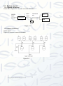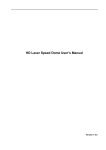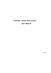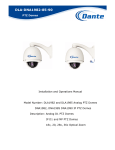
1
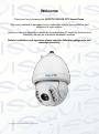
APOPTZ-18IR IR High Definition Speed Dome User’s Manual V1.0 07 / 2013 © Copyright Qvis® All documentation rights reserved. i Welcome Thank you for purchasing the APOPTZ-18IR HD PTZ Speed Dome. This user’s manual is designed to be a reference tool for the installation and operation of your system. Here you can find information about the corresponding IP camera’s features and functions, as well as a detailed installation method. Before installation and operation please read the following safeguards and warnings carefully! © Copyright Qvis® All documentation rights reserved. ii Table of Contents 1 FEATURES AND FUNCTIONS ................................................................................................ 1 1.1 General Introduction .......................................................................................................................................................... 1 1.2 Features .............................................................................................................................................................................. 1 1.2.1 On-Screen Menu ........................................................................................................................................................... 1 1.2.2 Support multiple protocols ........................................................................................................................................... 1 1.2.3 Proportional Pan and Tilt.............................................................................................................................................. 1 1.2.4 On-screen Tips .............................................................................................................................................................. 1 1.2.5 Preset Setup and Call................................................................................................................................................... 1 1.2.6 Auto Scan ....................................................................................................................................................................... 2 1.2.7 Auto Touring .................................................................................................................................................................. 2 1.2.8 Auto Pattern ................................................................................................................................................................... 2 1.2.9 Privacy Masking ............................................................................................................................................................ 2 1.2.10 Action on Alarm ........................................................................................................................................................ 2 1.2.11 Auto Flip ..................................................................................................................................................................... 2 1.2.12 Self-diagnosis............................................................................................................................................................ 2 1.2.13 Day/Night Mode (B/W & Color Mode) ................................................................................................................... 2 1.2.14 Auto Focus ................................................................................................................................................................ 2 1.2.15 Backlight Compensation .......................................................................................................................................... 3 1.2.16 Pan Tilt and Zoom .................................................................................................................................................... 3 1.2.17 3D Intelligent Location ............................................................................................................................................. 3 1.2.18 Idle Status .................................................................................................................................................................. 3 1.2.19 Image Stabilizer/Flip ................................................................................................................................................ 3 1.3 Specifications ..................................................................................................................................................................... 4 1.3.1 Performance Specifications ......................................................................................................................................... 4 1.3.2 Technical Specifications ............................................................................................................................................... 5 2 QUICK CONFIGURATION TOOL ............................................................................................. 6 2.1 Overview ............................................................................................................................................................................. 6 2.2 Operation............................................................................................................................................................................. 6 3 WEB OPERATION ................................................................................................................... 9 © Copyright Qvis® All documentation rights reserved. iii 3.1 Network Connection .......................................................................................................................................................... 9 3.2 Login and Logout ............................................................................................................................................................... 9 4 MENU ..................................................................................................................................... 12 4.1 Screen Menu Index ........................................................................................................................................................ 12 4.2 Self-diagnosis System Information ................................................................................................................................ 13 4.3 Main Menu ........................................................................................................................................................................ 13 4.4 Menu Operation .............................................................................................................................................................. 14 4.4.1 System Information ........................................................................................................................................ 14 4.4.2 Display Setting ............................................................................................................................................... 16 4.4.3 Camera Setting .............................................................................................................................................. 16 4.4.4 Function Setting ............................................................................................................................................. 21 4.5 Dome Troubleshooting................................................................................................................................................. 30 4.5.1 Restore to Factory Default Setup ............................................................................................................................. 30 4.5.2 PTZ Movement is not smooth ................................................................................................................................... 30 5 CABLE CONNECTION ........................................................................................................... 31 5.1 System Layout ................................................................................................................................................................ 33 5.1.1 System Connection ..................................................................................................................................................... 33 5.1.2 Alarm Connection ........................................................................................................................................................ 33 6 FAQ ........................................................................................................................................... 34 1.1 Daily Maintenance ......................................................................................................................................................... 34 1.2 Problems and Solutions............................................................................................................................................... 34 7 APPENDIX Ⅰ THUNDER PROOF AND SURGE PROTECTION ............................................. 35 8 APPENDIX 2 TOXIC OR HAZARDOUS MATERIALS OR ELEMENTS ................................. 36 © Copyright Qvis® All documentation rights reserved. iv © Copyright Qvis® All documentation rights reserved. v Important Safeguards and Warnings 1.Electrical safety All installation and operation here should conform to your local electrical safety codes. We assume no liability or responsibility for all the fires or electrical shock caused by improper handling or installation. We are not liable for any problems caused by unauthorized modification or attempted repair. 2.Transportation Security No heavy stress, violent vibration or contact with water is allowed during transportation, storage and installation. Please use the original packing material (or the material of the same quality) when you ship it back to the manufacturer. 3.Installation Do not apply power to the product before completing installation. Do not put object(s) on the product. 4.Environment This product should be installed in a cool, dry place away from direct sunlight, inflammable, explosive substances and etc. Please keep it away from environments that contain electromagnetic radiation or objects that produce it. Please keep sound ventilation around the device at all times. Do not allow the water and other liquid to penetrate into the device if casing has been compromised. This series product complies with the IP66 standard specified in the Degrees of Protection Provided by Enclosure. Please make sure the CCD (CMOS) component is away from the radiation of the laser beam device. Otherwise it may result in CCD (CMOS) optical component damage. 5. Daily Maintenance Current series product has no power button. Please unplug all corresponding power cables before your begin installation or daily maintenance work. Please keep the dustproof cap back to protect the CCD or CMOS part if the device does not work for a long time. Do not touch CCD (CMOS) component. You can use the blower to clean the dust on the surface of the device. You can use the dry cloth with some alcohol or mild detergent to clear if necessary. Do not use volatility solvent such as the benzene or thinner, or detergent with strong abradability. It may result in lens damage or it may adversely affect the device performance. © Copyright Qvis® All documentation rights reserved. vi If there is too much dust, please use the water to dilute the mild detergent first and then use it to clean the device. Finally use the dry cloth to clean the device. 6. About Accessories Always use all the accessories recommended by manufacturer. Before installation, please open the package and check that all the components are included in the package. Contact your local retailer ASAP if something is missing in your package. © Copyright Qvis® All documentation rights reserved. vii 1 Features and Functions 1.1 General Introduction The six-inch megapixel high speed smart network dome camera integrates the functions of network-based remote surveillance and integrated high-speed smart dome, which makes it convenient to install and easy to use. This product incorporates a megapixel level resolution, which meets the customers' needs for surveillance at HD level. This product is also qualified with intelligent identification ability, privacy masking settings, alarm activation, WDR and some other functions. In addition, one can transmit audio/video and control data via internet in a safe way. Thus, the surveillance is free from the restriction caused by the changes of time and places to realize a real-time surveillance. With the built-in high-speed PTZ, this product can operate as a quick and accurate, fixedpositioning surveillance, which is also very convenient to use. 1.2 Features This series speed dome has the following features: 1.2.1 On-Screen Menu This series product menu supports multiple languages. It is easy for you to view dome information and configure dome, camera parameters. 1.2.2 Support multiple protocols You can use various devices (such as matrix, control keyboard and DVR) and protocols to operate speed dome. 1.2.3 Proportional Pan and Tilt This function keeps the image from moving too fast when there is a large amount of zoom. The quick-installed high definition speed dome continually decreases or increases pan and tilt speeds in proportion to depth of zoom. When zooms speed is increasing, the camera moving speed becomes slow. When zooms speed is decreasing, the camera moving speed becomes fast. 1.2.4 On-screen Tips Here you can view: Dome title and system version (Software and hardware) Dome system temperature. (Optional. You can disable this function) Dome pan/tilt coordinates, preset ID. 1.2.5 Preset Setup and Call Preset function is to save the address information (such as PTZ pan/tilt, focus, etc) to the memory so that you can quickly adjust the dome and PTZ to the correct position. This series quick-installed high definition speed dome supports 255 presets. 1 © Copyright Qvis® All documentation rights reserved. 1.2.6 Auto Scan Camera scans back and forth regularly in a horizontal field. Here you need to set left and right limit and scan speed. You can set 5 scanning paths. 1.2.7 Auto Touring Add addresses into a routine and desired order and then set time and stop duration for each address. The dome will begin an auto touring between these addresses. Each touring path can contain max 32 presets. 1.2.8 Auto Pattern Memorise dome operation such as pan, tilt, and zoom to repeat. You can call it to repeat the previous operation. 1.2.9 Privacy Masking Privacy masking is a user-defined, four-sided area that cannot be viewed by you. The masking area will move with pan and tilt functions and automatically adjust in size as the lens zooms. 1.2.10 Action on Alarm System can connect 7-channel NO/NC input and 2-channel NO alarm output via the socket connector. Alarms can be individually programmed to initiated pattern, or go to an associated preset, scanning, touring when received. Dome will return to a previously programmed state after alarm acknowledgement or to its previous position before alarm. 1.2.11 Auto Flip As long as you continue to hold the keyboard joystick in the down position, the dome rotates 180 degrees and repositions itself for uninterrupted viewing of any subjects that passes directly beneath the dome. 1.2.12 Self-diagnosis There is a self-diagnosis procedure when dome boots up. Tilt and vertical engine check Camera diagnostics Display dome information and diagnosis information such as address, protocol, baud rate, type. 1.2.13 Day/Night Mode (B/W & Color Mode) Auto/manual switches in low illumination. Auto: camera will automatically adjust CCD light level. Manual: use menu or function keys to select day/night mode. This function needs the speed dome driver (camera) supported. 1.2.14 Auto Focus Auto focus allows the lens to remain in focus during zoom-in, zoom-out and motion functions to get vivid image. You can use FAR or NEAR button to adjust focus manually. 2 © Copyright Qvis® All documentation rights reserved. 1.2.15 Backlight Compensation Balance the brightest and darkest sections of a scene to produce a more vivid picture. 1.2.16 Pan Tilt and Zoom Supports zoom in and zoom out during tilt and pan movement. In this period focus and iris are both in auto mode to get clear image. 1.2.17 3D Intelligent Location Working with DVR, just click part of the current scene will be displayed in the central window and automatically zooms. All of these allow you to trace precisely. 1.2.18 Idle Status When there is no available order, you can use the menu to set dome idle status after specified duration. The idle status includes turn to specified preset or go to scan, tour or pattern function. 1.2.19 Image Stabilizer/Flip You can enable image stabilizer function and flip in the menu. When there is vibration, this IS function can guarantee video stability and when flip, you can view the video more clearly. This function needs speed dome driver (camera) supported. 3 © Copyright Qvis® All documentation rights reserved. 1.3 Specifications 1.3.1 Performance Specifications All digital design. All data are in the connection board. No data loss when power off occurs. Built-in Decode Built-in PTZ Built-in zoom lens, high sensitive, high resolution integrated digital process color camera. Fine stepper driver, stable performance, react quickly, precisely positioning. Integrated design, tight structure. Elegant mechanical driver device. Support 360 degrees continuous rotation, no monitor blind spot. 0.1°/s rotation speed while maintain stable image. 180 degrees tilt continuous monitor. Auto focus Auto BLC Auto brightness control Auto white balance Auto day/night switch (Auto B/W & color switch) OSD Integrated design, high stability. Quick-installed high definition speed dome max support 255 presets. Support 8 auto touring. Each touring max has 32 presets. Low and medium speed dome max support 80 presets. 5 auto scan. 5 auto pattern. Each pattern can max support 400 commands and the interval shall be less than 60s. Built-in direction indicator. Support max 24 privacy mask zones(Depends on the camera type) 7-channel alarm input, 2-channel alarm output. Preset title display View dome initial setup information Modify camera parameter Set preset Set auto scan Set auto patter Set 2-channel alarm input and 1-channel alarm output. Set auto day/night switch (Auto B/W & color switch) Set privacy mask zones 4 © Copyright Qvis® All documentation rights reserved. 1.3.2 Technical Specifications Power Camera Driver Consumption Decoder Engine Preset Auto Tour Auto Pattern Auto Scan Privacy Mask Alarm Input/Output Information Lens Auto Rotation Auto Pan Manual Pan Motion Speed Preset Maximum Speed Manual Tilt Motion Manual Tilt Scan Section PTZ Scan Accuracy Signal Format S/N Ratio Humidity Environment It depends on the product your purchase. 12W Built-in Stepper motor 255(PELCO-D protocol). 80 (In industrial protocol) Please note the value may vary due to different protocols. 8 5 5 8 zones in one-window. The different series products support different amount. It depends on the camera type. 7-channel alarm input and 2-channel alarm output. (Default setup is 2-channel alarm input and 1-channel output.) Time, address, dome title, dome coordinates, temperature, alarm and etc. Adjust speed in accordance with lens Tilt 92º auto rotates to pan 180 º 0 º -360º continuously 0.1º—300º/S 400º 0.1º—120º/S 0º—180º 0.06 ± 0.015º PAL/NTSC (Camera mode) > 50dB <90% -40℃—60℃(outdoor) 5 © Copyright Qvis® All documentation rights reserved. 2 Quick Configuration Tool 2.1 Overview Quick configuration tool can search the current IP address or/and modify IP address. At the same time, you can use it to upgrade the device. Please note the tool only applies to the IP addresses in the same segment. 2.2 Operation Double click the ‘ConfigTools.exe’ icon; you can see an interface is shown as in Figure 2-1. In the device list interface, you can view device IP address, port number, subnet mask, default gateway, MAC address and etc. Figure 2-1 Select one IP address and then right click mouse, you can see an interface is shown as in Figure 2-2. Figure 2-2 6 © Copyright Qvis® All documentation rights reserved. Select the ‘Open Device Web’ item; you can go to the corresponding web login interface. See Figure 2-3. Figure 2-3 If you want to modify the device IP address without logging in the device web interface, you can go to the configuration tool’s main interface to set. In the configuration tool search interface (Figure 2-1), please select a device IP address and then double click it to open the login interface. Or you can select an IP address and then click the Login button to go to the login interface. See Figure 2-4. In Figure 2-4, you can view device IP address, user name, password and port. Please modify the corresponding information to login. Please note: the port information here shall be identical with the port value you set in TCP port in Web Network interface. Otherwise, you cannot login to the device. If you are using the device background upgrade port 3800 to login, other setups all become invalid. Figure 2-4 7 © Copyright Qvis® All documentation rights reserved. After you logged in, the configuration tool main interface is shown as below. See Figure 2-5. Figure 2-5 8 © Copyright Qvis® All documentation rights reserved. 3 Web Operation This series product supports the Web access and management via PC. Web includes several modules: live view, PTZ, set, alarm, logout and etc. IP camera factory default setup: IP address: 192.168.1.108. User name: admin Password: admin 3.1 Network Connection Please follow the steps listed below for network connection. Make sure the IPC has connected to the network properly. IPC IP address and PC IP address shall be in the same network segment. IPC default IP address is 192.168.1.108. If there is router, please set the corresponding gateway and subnet mask. Use order ping ***.***.***.***(* IP camera address) to check connection is OK or not. 3.2 Login and Logout Open IE and input IP camera address in the address bar. For example, if your camera IP is 192.168.1.108, then please input http:// 192.168.1.108 in IE address bar. See Figure 3-1. Input your IP address here Figure 3-1 System pops up warning information to ask you whether install control webrec.cab or not. Please click OK button, system can automatically install the control. When system is upgrading, it can overwrite the previous Web too. If you can’t download the ActiveX file, please check whether you have installed the plug-in to disable the control download. Or you can lower the IE security level. See Figure 3-2. 9 © Copyright Qvis® All documentation rights reserved. Figure 3-2 After installation, the interface is shown as below. See Figure 3-3. 1. Please input your user name and password. 2. Default factory name is admin and password is admin. 3. Select the network connection type. 4. The login type includes: TCP/UDP/Multicast. Note: For security reasons, please modify your password after you first login. Figure 3-3 10 © Copyright Qvis® All documentation rights reserved. After you logged in, you can see the main window. See Figure 3-4. Figure 3-4 11 © Copyright Qvis® All documentation rights reserved. 4 Menu 4.1 Screen Menu Index Note: ERR means current setup is invalid. … means there is submenu. SYSTEM INFORMATION DISPLAY SETTING INITIAL INFORMATION… ADDR INFORMATION… SYSTEM TIME SETTING… SET NORTH LANGUAGE :ENGLISH FACTORY DEFAULT RESTART BACK EXIT PRESET TITLE : ON (ON/OFF) AZIMUTH DISP : ON (ON/OFF) TIME DISP : OFF (ON/OFF) POSITION : OFF (ON/OFF) ZOOM DISP : OFF (ON/OFF) INSIDE TEMP : ℃ (℃/F/OFF) TITILE DISPLAY :OFF BACK EXIT CAMERA SETTING WB SETTING EXPOSURE SETTING DAY/NIGHT SETTING PICTURE ADJUST FOCUS SETUP ZOOM SPEED : 08 (01-08) APERTURE : 06 (01-16) NEXT PAGE BACK EXIT FUNCTION SETTING EXIT PRESET AUTO PAN AUTO SCAN CRUISE PATTERN IDLE MOTION AUTO RUN NEXT PAGE BACK EXIT The above diagram illustrates the overall structure of the speed dome setup menu. Note: ERR means current setup is invalid. Please make sure all the cable connections are right. 12 © Copyright Qvis® All documentation rights reserved. 4.2 Self-diagnosis System Information ADDR BAUD RATE PARITY PROTOCOL SOFTWARE : : : :V1.04.3 After installation, please connect speed dome to power. The system goes on a self-diagnosis, and then it pops up the above interface to show the system information. If there is anything wrong during the self-diagnosis, system pops up error code. The above interface disappears after speed dome received the first command (or the display time lasts for 4 minutes.) ADDR: Here you can view dome address information. For example, 001-H, 1 is the address number, -H is hard address mode. –S is software address mode. Baud rate: Dome communication baud rate. Parity: Communication parity bit format. PROTOCOL:System can auto recognize industrial protocol, PELCOD, PELCOP. Software: Dome software version of the control firmware. When you are using the control keyboard or the matrix host to control the device, please make sure the control parameter of the keyboard or the matrix host is the same with the speed dome OSD (including address, baud rate, parity). Please make sure the cable connection is OK. 4.3 Main Menu You can open the IP dome menu via monitor platform, web, control keyboard, matrix, or speed dome control terminal. SYSTEM INFORMATION DISPLAY SETTING CAMERA SETTING FUNCTION SETTING IR LIGHT SETTING EXIT SYSTEM INFORMATION:Dome self-diagnosis information, address information, system time setup, set north direction, language, factory default setup, reboot and so on. DISPLAY INFORMATION: Display dome preset title, azimuth display, time, direction, dome internal temperature and etc information. CAMERA PARAMETERS:Display dome white balance setup, camera function setup, day/night setup, shutter setup and etc. FUNCTION SETTING: Set preset, pan, scan, auto cruise, pattern, idle motion, time task and privacy mask function. EXIT: Log out the system menu. 13 © Copyright Qvis® All documentation rights reserved. 4.4 Menu Operation In the speed dome main menu, you can use the left/right button on the keyboard or in the speed dome terminal menu to configure the system menu. Before setup, please move the cursor to the current item you want to configure. In main menu, please click confirm button to go to the sub menu or use left/right key to configure setup. Use up/down button to select back option and then click confirm button to go back to the previous menu. Use up/down button to select exit option and then click confirm button to log out system menu. All setup here will not lose when encounter power failure. 4.4.1 System Information INITIAL INFORMATION ADDR INFORMATION SYSTEM TIME SETTING SET NORTH LANGUAGE : ENGLISH FACTORY DEFAULT RESTART BACK EXIT INITIAL INFORMATION: Move the cursor to INITIAL INFORMATION and then click confirm button to go to the third submenu. ADDR INFORMATION: Move the cursor to SITE INFORMATION and then click confirm button to go to the third submenu. SYSTEM TIME SETTING: Move the cursor to SYSTEM TIME SETTING and then click confirm button to go to the third submenu. SET NORTH DIRECTION: Set dome benchmark direction so that you can know the angel between the benchmark and then current location. Please move the cursor to the option and then click confirm button until you see O.K. Now you have set north direction. LANGUAGE: The dome menu language. There are several languages for you to select. Please use the left/right button on the keyboard or in the speed dome terminal menu to set. FACTORY DEFAULT: Restore dome factory default setup. Please move the cursor to the option and then click confirm button until you see O.K. Now you can see the IP dome begin rebooting to restore factory default setup. RESTART: Reboot the speed dome. BACK: Go back to the previous menu. EXIT: Log out system menu. 14 © Copyright Qvis® All documentation rights reserved. 4.4.1.1 Initialisation information ADDR BAUD RATE PARITY SOFTWARE BACK EXIT : 001-H :9600 :NONE :vX.XX.XX Move the cursor to INITIAL INFORMATION and then click confirm button, you can see the above interface. Here you can view dome basic information. 4.4.1.2 Address Information ADDR TYPE ADDR-HARD ADDR-SOFT BACK EXIT : HARD : 001 : 001 Move the cursor to SITE INFORMATION and then click confirm button. ADDR TYPE: There are two options: soft and hard. Please use the left/right button on the keyboard or in the speed dome terminal menu to set. Please click the OK button to confirm ADDR-HARD: It is an address you set in the dial switch. You cannot modify it through software. ADDR-SOFT: You can set address via software. It is to say, you can use menu to modify dome address. The value ranges from 1 to 255. BACK: Go back to the previous menu. EXIT: Log out system menu. 4.4.1.3 System Time Setting YEAR : 2009 MONTH : 001 DATE : 017 WEEK : SUNDAY HOUR : 013 MINU: : 052 SAVE BACK EXIT Move the cursor to SYSTEM TIME SETING and then click confirm button, you can go to the third submenu. Please use the left/right button on the keyboard or in the speed dome terminal menu to set. After completed setup, please click confirm button to save current setup. After you see speed dome menu displays OK, you can see the setup is valid now. 15 © Copyright Qvis® All documentation rights reserved. 4.4.2 Display Setting PRESET TITLE AZIMUTH DISP TIME DISP POSITION ZOOM DISP INSIDE TEMP TITLE DISP BACK EXIT :ON :ON :OFF :OFF :OFF :℃ :OFF Move the cursor to DISPLAY SETUP and then click confirm button, you can go to the third submenu. Please use the left/right button on the keyboard or in the speed dome terminal menu to set. After completed setup, please click save button to save current setup. PRESET TITLE: Display dome preset title or not. Please use the left/right button on the keyboard or in the speed dome terminal menu to set. You can go to Function Setup->Preset section to set corresponding preset value and preset title. AZIMUTH DISP: Display dome current coordinates or not. Please use the left/right button on the keyboard or in the speed dome terminal menu to set TIME DISP: Display dome system time or not. Please use the left/right button on the keyboard or in the speed dome terminal menu to set. POSITION: Display the angel between the benchmark and then current location. Please use the left/right button on the keyboard or in the speed dome terminal menu to set. ZOOM DISP: Display speed dome zoom speed or not. Please use the left/right button on the keyboard or in the speed dome terminal menu to set. INSIDE TEMPERATURE: Display dome internal temperature or not. There are three options: ℃/F/Off. Please use the left/right button on the keyboard or in the speed dome terminal menu to set. TITLE DISPLAY: Here you can set to display speed dome position information and etc. You can use the speed dome control terminal to set the detailed title information. Please use the left/right button to set. BACK: Go back to the previous menu. EXIT: Log out system menu. 4.4.3 Camera Setting WB SETTING EXPOSURE SETTING DAY/NIGHT SETTING FOCUS SETUP PICTURE ADJUST ZOOM SPEED : 08 APERTURE : 09 NEXT PAGE BACK EXIT Move the cursor to CAMERA SETTING and then click confirm button, you can go to the submenu. WHITE BALANCE SETUP: Move the cursor to current option and then click confirm button, you can go to the third menu. 16 © Copyright Qvis® All documentation rights reserved. EXPOSURE SETTING: Move the cursor to current option and then click confirm button, you can go to the third menu. DAY/NIGHT: Set day/night mode. Move the cursor to current option and then click confirm button, you can go to the third menu. There are three options: auto/manual/off. Please use the left/right button on the keyboard or in the speed dome terminal menu to set. Please make sure your product supports this function. FOCUS SETUP: It is to set camera focus mode, focus limit and etc. Please use the left/right button on the keyboard or in the speed dome terminal menu to set. PICTURE ADJUSTMENT: It is to set the camera hue, saturation, color control, gamma, contrast, brightness. There is the third menu. Please move the light to highlight current item and then click the OK button to go to the next level menu. FOCUS LIMIT: It is to set the distance between the camera and the object. It can prevent the focus distance is too small which may result in focusing on the enclosure. At the same time, you can change the distance to change the focus speed. ZOOM SPEED: The bigger the value, the faster the speed. Please use the left/right button on the keyboard or in the speed dome terminal menu to set. APERTURE: It is to adjust the lens to achieve clear video. Please use the left/right button on the keyboard or in the speed dome terminal menu to set. NEXT PAGE: It includes the following options: APERTURE RESTRAIN. DIGITAL ZOOM, PICTURE FLIP, FREEZE FUNCTION, AF SENSITIVITY, CAMERA FACTORY DEFAULT SETUP, CAMERA RESTART. Please use the left/right button on the keyboard or in the speed dome terminal menu to set. BACK: Go back to previous menu. EXIT: Log out system menu. 4.4.3.1 White Balance Setup WB MODE : AUTO R GAIN : 001 B GAIN : 001 BACK EXIT Move the cursor to WHITE BALANCE MODE and then click confirm button, you can go to the submenu. WHITE BALANCE MODE: Set white balance adjustment mode. There are two modes: auto/manual. Please use the left/right button on the keyboard or in the speed dome terminal menu to set. R GAIN: Before you set R GAIN option, please note the mode shall not be auto. Please use the left/right button on the keyboard or in the speed dome terminal menu to set. B GAIN: Before you set B GAIN option, please note the mode shall not be auto. Please use the left/right button on the keyboard or in the speed dome terminal menu to set. BACK: Go back to previous menu. EXIT: Log out system menu. 17 © Copyright Qvis® All documentation rights reserved. 4.4.3.2 Exposure Setting AE MODE GAIN SETTING SHUTTER IRIS SETTING EXPOSURE COMP SLOW AE SLOW SHUTTER NEXT PAGE BACK EXIT : AUTO : 02 : 1/50 : 11 : 08 : 01 ON AGC GAIN LIMIT SLOW SHUTTER LIMIT NOISE REDUCTION BLC WDR ENABLE BACK EXIT : 03 : 1/25 : 03 : ON : ON AE MODE: Here you can set the camera exposure mode. It includes: auto/manual/AV (iris priority)/TV (shutter priority). Please use the left/right button on the keyboard or in the speed dome terminal menu to set. o Auto: It becomes valid after you set the exposure compensation, backlight compensation (BLC), slow shutter, wide dynamic region (WDR). o Manual: It becomes valid after you set the gain setting, shutter, iris setting, wide dynamic region (WDR). o AV: It becomes valid after you set the exposure setting, iris setting, wide dynamic region (WDR). o TV: It becomes valid after you set the shutter setting, exposure compensation, wide dynamic region (WDR). GAIN SETTING: Please use the left/right button on the keyboard or in the speed dome terminal menu to set. SHUTTER: Please use the left/right button on the keyboard or in the speed dome terminal menu to set. IRIS SETTING: Please use the left/right button on the keyboard or in the speed dome terminal menu to set. EXPOSURE COM: Please use the left/right button on the keyboard or in the speed dome terminal menu to set. SLOW AE: In the strong light environment, you can lower the camera exposure speed to capture the image and enhance the definition. Please use the left/right button on the keyboard or in the speed dome terminal menu to set. SLOW SHUTTER: In lower illumination environment, you can lower the cameras auto exposure time to capture the image and enhance the definition. Please use the left/right button on the keyboard or in the speed dome terminal menu to set. NEXT PAGE: It includes: AUTO GAIN LIMIT, AUTO SLOW SHUTTER LOW LIMIT, NOISE CONTROL, 3D NOISE REDUCTION, BLC, WDR, BACK, and EXIT. Move the cursor to the item and then click the left/right button to set. o AUTO GAIN LIMIT: Please click the left/right button to set. o SLOW SHUTTER LOW LIMIT: Please click the left/right button to set. o NOISE REDUCTION: There may noise when the camera is monitoring the low illumination environments. You can use the digital filter to process the noise to guarantee the clear video. o 3D NOISE REDUCTION o BLC: It is an abbreviation for back light compensation. System can compensate the object in the dark light to achieve a clear video. Please use the left/right button on the keyboard or in the speed dome terminal menu to set. o WDR ENBALE: It is an abbreviation for wide dynamic region. Please make sure your camera supports current function. This function can adjust the video brightness when the contrast 18 © Copyright Qvis® All documentation rights reserved. between the strong light and the dark light is too high. Please use the left/right button on the keyboard or in the speed dome terminal menu to set. BACK: Go back to previous menu. EXIT: Log out system menu. 4.4.3.3 Day/Night Setting Move the cursor to DAY/NIGHT SETTING and then click confirm button, you can go to the submenu. DAY/NIGHT DAY TIME NIGHT TIME THRESHOD SAVE BACK EXIT :AUTO :07H 00M : 19H 00M :4 DAY/NIGHT: Please use the left/right button on the keyboard or in the speed dome terminal menu to set. DAY TIME: Current setup becomes valid when day/night mode is Time. Move the cursor to DAY TIME item and then click confirm button to go to setup. Please user up/down button to set the value. After completed setup, please click confirm button to exit and move the cursor to Save button to save current setup. NIGHT TIME: Current setup becomes valid when day/night mode is Time. Move the cursor to DAY TIME item and then click confirm button to go to setup. Please user up/down button to set the value. After completed setup, please click confirm button to exit and move the cursor to save button to save current setup. THRESHOLD: The speed dome can switch the day/night mode when it reached the threshold you set here. SAVE: This button is for DAY TIME and NIGHT TIME setup. After you set the day time (or night time), you need to move the cursor here and then click confirm button to save current time setup. For other setups, you do not need to use this button. BACK: Go back to previous menu. EXIT: Log out system menu. 4.4.3.4 Picture Adjustment HUE : SATURATION : COLOR CONTROL: GAMA: CONTRAST : HIGH LIGHT: BACK EXIT HUE: It is to set the video hue. Please use the left/right button on the keyboard or in the speed dome terminal menu to set. SATURATION: It it to set the video saturation. Please use the left/right button on the keyboard or in the speed dome terminal menu to set. 19 © Copyright Qvis® All documentation rights reserved. COLOR CONTROL: It is to set the video color control. Please use the left/right button on the keyboard or in the speed dome terminal menu to set. GAMA: It is to set the video gama. Please use the left/right button on the keyboard or in the speed dome terminal menu to set. CONTRAST: It is to set the video contrast. Please use the left/right button on the keyboard or in the speed dome terminal menu to set. HIGH LIGHT: It is to set the video high light. Please use the left/right button on the keyboard or in the speed dome terminal menu to set. BACK: Go back to previous menu. EXIT: Log out system menu. 4.4.3.5 Focus Setup FOCUS MODE : FOCUS LIMIT: FOCUS SENSITIVITY : IR LIGHT FOCUS CORRECTION: BACK EXIT FOCUS MODE: It is to set the camera focus mode. It includes several modes such as auto, manual, semiautomatic. FOCUS LIMIT: It is to set the camera focus limit. Please use the left/right button on the keyboard or in the speed dome terminal menu to set. FOCUS SENSITIVITY: It is to set the camera focus sensitivity. Please use the left/right button on the keyboard or in the speed dome terminal menu to set. IR LIGHT FOCUS CORRECTION: It is to set the camera IR light focus correction. Please use the left/right button on the keyboard or in the speed dome terminal menu to set. BACK: Go back to previous menu. EXIT: Log out system menu. 4.4.3.6 Next Page Move the cursor to NEXT PAGE and then click confirm button, you can go to the submenu. APERTURE RESTRAIN 16 : DIGITAL ZOOM : OFF PICTURE FLIP : OFF FREEZE FUNC : OFF AF SENSITIVITY: : NORMAL CAMERA FACTORY DEFAULT CAMERA RESTATRT BACK EXIT APERTURE RESTRAIN: It can automatically control the aperture in the low illumination environments. It can reduce the noise. DIGITAL ZOOM: You can use the left/right button to enable/disable the digital zoom function. 20 © Copyright Qvis® All documentation rights reserved. PICTURE FLIP: This function allows you to turn the image rotation 180 degrees. There are two options: on/off. Please use the left/right button on the keyboard or in the speed dome terminal menu to set. FREEZE FUNCTION: This function allows the system from one preset to another preset, without showing the video during the PTZ movement. There are two options: on/off. Please use the left/right button on the keyboard or in the speed dome terminal menu to set. AF SENSITIVITY: You can set the auto focus threshold value here. CAMERA FACTORY DEFAULT SETTING: Move the cursor to current item and then click confirm button to restore factory default setup. CAMERA RESTART: Move the cursor to current item and then click confirm button to reboot the camera. BACK: Go back to previous menu. EXIT: Log out system menu. 4.4.4 Function Setting PRESET PAN AUTO SCAN AUTO CRUISE AUTO PATTERN IDLE MOTION TIME TASK NEXT PAGE BACK EXIT Please go back to main menu and move the cursor to FUNCTION SETTING, click confirm button. You can see the above interface. PRESET: Move the cursor to PRESET and then click confirm button to go to the third submenu. PAN: Move the cursor to PAN and then click confirm button to go to the third submenu. AUTO SCAN: Move the cursor to SCAN and then click confirm button to go to the third submenu. AUTO CRUISE: Move the cursor to AUTO CRUISE and then click confirm button to go to the third submenu. AUTO PATTERN: Move the cursor to PATTERN and then click confirm button to go to the third submenu. IDLE MOTION: Move the cursor to IDLE MOTION and then click confirm button to go to the third submenu. TIME TASK: Move the cursor to TIME TASK and then click confirm button to go to the third submenu. NEXT PAGE: It includes: PRIVACY MASKING, PTZ SPEED, SET ZERO, POWER UP, MENU PASSWORD, MENU IDEL, PTZ AUTO STOP, and HEATER. Move the cursor to the item and then click the confirm button to set. . BACK: Go back to previous menu. EXIT: Log out system menu. 21 © Copyright Qvis® All documentation rights reserved. 4.4.4.1 Preset Setup PRESET NO :001 TITLE :PRESET001 SETTING CALL BACK EXIT Move the cursor to PRESET button and then click confirm button to go to set interface. PRESET NO: Please use left/right key to modify preset number. The different protocols support different preset values. The PELCOD and PELCOP support 1 to 255. For the industrial protocol, the value ranges from 1 to 80. TITLE:Title text is the label used for you to identify the camera. System will automatically name a title for the camera. SETTING: Please input preset number first and then select the monitor zone. Please move the cursor to setting and click confirm button. The system will pop up a message: PRESET: ***. Here *** means preset number. And the SETTING column pops up an OK. Now you successfully added a preset. Please note, you need to enable display preset title function first (Main menu->display setting->preset title).Repeat the above procedures to set more presets. Once you want to modify a preset, you can input the preset number you want to modify and then follow the above steps to set the preset. You can successfully modify a preset content. CALL: Here is to recall preset. Move the cursor to PRESET NO and then input corresponding preset value. Then move the cursor to CALL and then click confirm button to go to a preset. BACK: Go back to previous menu. EXIT: Log out system menu. For PELCO protocol user, please refer to the following special functions: Call preset: Call preset 28 or preset 95 to go to dome menu. Call preset 29 or preset 99 to go to scan. Call preset 24 or preset 81 to go to pattern. Call preset 25 or preset 82 to go to cruise (tour). Call preset 30 or preset 96 to stop scan or pattern. Call preset 31 or preset 83 to begin rotation. Call preset 33 to enable PTZ 180 degrees rotation. Call preset 34 to set dome position as 0. Set preset: Set preset 26 or 92 to set scan left limit. Set preset 27 or 93 to set scan right limit. Set preset 22 or 79 to begin record. Set preset 23 or 80 to stop record. 22 © Copyright Qvis® All documentation rights reserved. 4.4.4.2 Pan PAN SPEED RUN STOP BACK EXIT :160 Move the cursor to PAN button and then click confirm button to go to setup interface. PAN SPEED: Set dome rotation speed. Please use the left/right button on the keyboard or in the speed dome terminal menu to set. RUN: Move the cursor to call item and then click confirm button. The dome begins 360 degrees continuous rotation. STOP: Highlight stop item and then click confirm button. The dome stops rotation. BACK: Go back to previous menu. EXIT: Log out system menu. 4.4.4.3 Scan SCAN NO : 001 SET LEFT LIMIT SET RIGHT LIMIT SCAN SPEED :160 RUN STOP BACK EXIT Move the cursor to SCAN button and then click confirm button. SCAN NO:Here is to set auto scan number. Please use the left/right button on the keyboard or in the speed dome terminal menu to set. SET LEFT LIMIT:Here is to set camera left address. Click confirm button to save current setup. SET RIGHT LIMIT:Here is to set camera right address. Click confirm button to save current setup. SCAN SPEED: Please use the left/right button on the keyboard or in the speed dome terminal menu to set. RUN: Please input auto scan number first, and then please move the cursor to RUN and click confirm button to activate auto scan function. STOP: Here is to terminate auto scan function. BACK: Go back to previous menu. EXIT: Log out system menu. 23 © Copyright Qvis® All documentation rights reserved. 4.4.4.4 Cruise (Touring) CRUISE NO: : 001 CRUISE SETTING DELETE CRUISE RUN STOP BACK EXIT Move the cursor to highlight CRUISE item and then click confirm button to go to set interface. CRUISE NO :Here is to set the tour number. Please use the left/right button on the keyboard or in the speed dome terminal menu to set. CRUISE SETTING: Move the cursor to cruise setting item and then click confirm button. You can see the following interface. Here you can add or remove the preset, and set the corresponding dwell time and call speed. NO 01 02 03 … 32 PRESET DWELL 000 005 000 005 000 005 … … 000 005 SPEED 013 013 013 … 013 DWELL: Here is to set the dwell time. Please use the left/right button on the keyboard or in the speed dome terminal menu to set. SPEED: Here you can set the speed value. When you move the cursor to one cruise number, you can use left/right button to turn the page. When you move the cursor to one cruise number, please click confirm button to set the cruise. Please use up/down button to set preset number, dwell time and speed. Use the left/right button to go to the next cruise. Click confirm button you can exit the setup. After you completed the setup, move the cursor to back button to go to the previous interface. DELETE CRUISE:This deletes a cruise. Input cruise number in CRUISE NO and then move the cursor to DELETE cruise, click confirm button to delete. CALL: Here is to activate cruise. Input touring number in touring NO and highlight CALL, click confirm button to activate touring. STOP: Here is to terminate touring. BACK: Go back to previous menu. EXIT: Log out system menu. 24 © Copyright Qvis® All documentation rights reserved. 4.4.4.5 Pattern PATTERN NO: 001 PROGRAM START PROGRAM STOP RUN STOP BACK EXIT Pattern function can memory PTZ operation and camera focus zoom in and zoom out. From the start position, dome begins auto movement repeatedly. This series IP dome supports maximum 5 patterns and one pattern can max support 400 commands. Move the cursor to PATTERN and click confirm button. PATTERN NO: Here is to set pattern number. The value ranges from 1 to 5. Please click left/right key to configure. PROGRAM START: Here is to memorize pattern starting point. An icon OK pops up in screen to prompt you system begins memory pattern. PROGRAM STOP:Here is to set pattern stop point. After all the movement, move the cursor to PROGRAM STOP and then click confirm button. Now you have set one pattern. System pops up an icon OK to prompt you system has memories one pattern. RUN:Here is to activate pattern. Input pattern number, move the cursor to RUN and click confirm button, system begins running pattern. STOP: Here is to stop current pattern. Input pattern number, move the cursor to STOP and click confirm button. System stops current pattern. BACK: Go back to previous menu. EXIT: Log out system menu. Note: The dwell time between two orders should be less than one minute, otherwise system will set to default value as one minute. After click PROGRAM STOP, do not click CALL button before icon “●” disappears completely. Any manual operation during the pattern procedure will terminate current dome pattern operation. 25 © Copyright Qvis® All documentation rights reserved. 4.4.4.6 Idle Motion IDLE FUNC :OFF IDLE TIME :010MIN IDLE ACTION :PRESET SN: SAVE BACK EXIT When there is no available command for specified time, dome automatically goes on the previous set functions. IDLE FUNCTION :There are two modes ON/OFF. Please use left/right key to set. IDLE TIME: System idle period. Please use the left/right button on the keyboard or in the speed dome terminal menu to set. IDLE ACTION:There are several functions you can select: NONE/PRESET/SCAN/TOURING/PATTERN. Please use the left/right button on the keyboard or in the speed dome terminal menu to set. SN: It is the serial number of the None/preset/scan/tour/pattern when the system is idle. SAVE:Move the cursor to SAVE and click confirm button to save current setup. BACK: Go back to previous menu. EXIT: Log out system menu. 4.4.4.7 Auto Run (Schedule task) TASK NO :1 TIME TASK :OFF TASK SETTING TASK INFORMATION DELETE TASK BACK EXIT TASK NO: Here you can set task number. Please use the left’/right button to set. TIME TASK: The schedule task allows the speed dome to implement corresponding setup during the specified time. There are two options: on/off. Please use the left/right button on the keyboard or in the speed dome terminal menu to set. TASK SETTING: Here you can set task time, operation, operation SN and etc. Please click the confirm button to go to the fourth menu to set. TASK INFORMATION: Here you can view the corresponding task information. Please click the confirm button to go to the fourth menu to set. DELETE TASK: Please input the task number to be deleted in the TASK NO, and then move the cursor to the current item. Click the confirm button, you can remove all the setups in the current schedule task. Now current task is null. BACK: Go back to the previous menu. EXIT: Log out the system menu. 26 © Copyright Qvis® All documentation rights reserved. Task Setting Move the cursor to the TASK SETTING and then click the confirm button, you can set the task begin time, end time, action and etc. :1 :OFF WEEK START TIME END TIME RUN ACTION PRESET NO SAVE BACK EXIT WEEK: Here you can set the week information. Please use the left/right button to set. You can set for one day, or you can set for the whole week. START TIME: Here you can set the task begin time. Move the cursor to current item and then click confirm button to set the time. Please use the up/down button to set the detailed value and then use left/right button to go to the next setup item. After you completed the setup, please click confirm button to exit start time setup and then move the cursor to the SAVE button to save current setup. END TIME: Here you can set the task end time. Move the cursor to current item and then click confirm button to set the time. Please use the up/down button to set the detail value and then use left/right button to go to the next setup item. After you completed the setup, please click confirm button to exit end time setup and then move the cursor to the SAVE button to save current setup. TASK ACTION: The option here includes: none/tour/scan/preset/patter and etc. Please use left/right button to set. OPERATION NO: It is the corresponding serial number of the schedule task. The number here may vary due to different action types. BACK: Go back to the previous menu. EXIT: Log out the system menu. Task Information Move the cursor to the TASK INFORMATION and then click the confirm button to go to the following interface. Here you can see the corresponding task information. Click the confirm button again, you can exit current interface. NO TIME ACTION 1 ALL 00:00-00:00 SC001 OFF 2 ALL 00:00-00:00 SC001 OFF 3 ALL 00:00-00:00 SC001 OFF 4 ALL 00:00-00:00 SC001 OFF 5 ALL 00:00-00:00 SC001 OFF 6 ALL 00:00-00:00 SC001 OFF 7 ALL 00:00-00:00 SC001 OFF 8 全星期 00:00-00:00 线扫 1 关 27 © Copyright Qvis® All documentation rights reserved. 4.4.4.8 Next Page Move the cursor to the NEXT PAGE and then click the confirm button, you can go to the third menu to set the PTZ SPEED, SET ZERO, POWER UP, etc. PRIVACY MASK PTZ SPEED SET ZERO POWER UP MENU PASSWORD MENU IDLE PTZ AUTO STOP SAVE BACK EXIT :1 :OFF PRIVACY MASK: Here you can set the privacy mask number, etc. It includes the third menu. Please move the cursor to the current item and then click the confirm button to go to the next interface. PTZ SPEED: It is to set PTZ speed. Please use the left/right button to set. SET ZERO: It is to set the PTZ initial position. Please move the PTZ to the corresponding position and then click the confirm button to complete the setup. POWER UP: It is to set the PTZ action when the speed dome boots up. Click the confirm button to go to the next interface. MENU PASSWORD: It is to set the password to go to the PTZ menu. Click the confirm button to go to the next interface. MENU IDLE: If current setup is ON, once you open the menu and leave it idle for specified period, the menu may automatically disappear. If current setup is OFF, the menu is always there and will not disappear. Please use the left/right button to set. PTZ AUTO STOP: The speed dome will stop all the PTZ operations when there is no command for the specified time. It includes various setups. Please use the left/right button to set. BACK: Go back to the previous menu. EXIT: Log out the system menu. Privacy Mask Move the cursor to PRIVACY MASK and click confirm button, system goes to privacy mask setup interface. PRIVACY :001 NO ACTIVATE : OFF RESIZE :↑ DELETE SAVE BACK EXIT 28 © Copyright Qvis® All documentation rights reserved. Note: For security reasons, please set privacy zone a little bit larger than the privacy object size. Each time, after modifications you need to move the cursor to SAVE button and then click confirm button to get all setup activated. Otherwise, privacy zone may not move correspondingly with the object. 1. Please enter privacy mask menu, now all the privacy zones are closed. 2. Move the cursor to PRIVACY NO, please use left/right key to set different privacy zones. 3. For example, shift to 001 section and then move the cursor to ACTIVATE. 4. Secondly, use left/right key to select ON mode. Now there is a privacy zone in the screen centre. 5. Thirdly, use PTZ to move camera so that privacy object fit well with screen centre. 6. Fourthly, move the cursor to RESIZE and then click left and right key to adjust privacy zone direction and size. 7. Fifthly, move the cursor to SAVE and then click confirm button to exit. PRIVACY NO:Here is to set privacy mask zones. Please use the left/right button on the keyboard or in the speed dome terminal menu to set. The value ranges from 1 to 24. Please note the value here may vary due to different protocols. ACTIVATE: There are two settings: on and off. When activate function is on, the privacy mask function will be activated and displays in the screen. When activate function is off, the privacy mask function will be closed and the blank will not displayed in the screen. RESIZE:It is to adjust the privacy zone size. Please continue pressing direction button to widen or narrow zone size. ← is to narrow the horizontal width and → is to widen the horizontal width. ↑ is to widen vertical height and ↓ is to narrow the vertical height. SAVE:Here is to save user setup. DELETE: Here is to delete setup and restore default setting. BACK: Go back to previous menu. EXIT: Log out system menu. Power Up Move the cursor to the POWER UP item and then click the confirm button, you can go to the fourth menu. POWER UP PARAMTER BACK EXIT :1 :OFF POWER UP: It is to set the PTZ operation when the speed dome boots up. The option includes: NONE/AUTO/SCAN/PRESET/PATTERN/TOUR and etc. Please use the left/right button to set. PARAMTER: Here you can set the serial number of the corresponding operation such as the scan, preset, pattern, tour. Please use the left/right button to set. BACK: Go back to the previous menu. EXIT: Log out the system menu. 29 © Copyright Qvis® All documentation rights reserved. Menu Password Move the cursor to the MENU PASSWORD and the click the confirm button to go to the fourth menu. PASSWORD: 1 2 3 4 5 SETTING 6 7 8 9 0 BACK → SAVE : PASSWORD BACK : EXIT PASSWORD: It is to set the speed dome menu password. Please use the left/right button to set. SETTING: Click the confirm button to go to the password setup interface. Please use the left/right button to set the value and then click the confirm button to confirm current option. Move the cursor to the SAVE button and then click the confirm button to save current setup. Click the BACK button to go to the previous menu. BACK: Go back to the previous menu. EXIT: Log out the system menu. If you have forgot your password. After three times of login failure, system may pop up an 8-digit internal code. Please contact our technical engineer for help. 4.5 Dome Troubleshooting 4.5.1 Restore to Factory Default Setup From main menu-> SYSTEM INFORMATION, move cursor to FACTORY DEFAULT and click confirm button. Dome will reboot and all the setups restore to factory default setup. 4.5.2 PTZ Movement is not smooth From menu to SYSTEM INFORMATION, move cursor to RESTART and click confirm button. This reboot will not modify all activated setup (such as preset, tour and pattern). 30 © Copyright Qvis® All documentation rights reserved. 5 Cable Connection Multiple-function combination cable consists of network cable, audio/video port, RS485 port, alarm input, output cable port. Please refer to the label for detailed information. 1) RS485 and audio/video port, power port and network port information is shown below: Name 485 A B Function 485-A port. It is to control the speed dome built-in PTZ. 485-A port. It is to control the speed dome built-in PTZ. GND Ground end. GND Ground OUT Video output port. You can connect this port if you want to use the analog video output. VIDEO Name Function POWER Power port. Please refer to the label for detailed information. EARTH Ground port. LAN Network port. Connect to the network cable. Please refer to the label instruction for the alarm connection information of the multiple-function combination cable. You can connect 485 port if you want to use the RS485 to control the network speed dome. Otherwise, you do not need to connect. 2.) Relay in/out interfaces is shown below: Name Alarm out;1-2 GND Alarm in:1-7 Function When there is an alarm from current channel, system activates relay or not. Device default setup is NO. NO:Normal open alarm output. For the default setup: 1-channel alarm input and 2-channel alarm output is optional. Alarm input ground end. 2-channel alarm input. It is to receive relay signal from the external alarm source. You can go to dome menu to activate specified preset or patter. When the activation mode is NO (normal open), dome alarms when there is low voltage. High voltage will not activate the alarm. When the activation mode is NC (normal close), dome alarms when there is high voltage. Low voltage will not activate the alarm. 31 © Copyright Qvis® All documentation rights reserved. Note: Dome alarm input message is ground mode. Dome alarm input signal are two modes: normal open and normal close. For the default setup: 2-channel alarm input and 7-channel alarm input is optional. 32 © Copyright Qvis® All documentation rights reserved. 5.1 System Layout 5.1.1 System Connection Please refer to Figure 5-1 for system connection information. AC24V Input Power Initialisation Output Info PC Transformer DVR Figure 5-1 5.1.2 Alarm Connection Please refer to Figure 5-2 for alarm connection information. Figure 5-2 33 © Copyright Qvis® All documentation rights reserved. 6 FAQ 1.1 Daily Maintenance Please clean dome cover regularly to continue receiving clear images. Handle the cover with care. Use water to wash. Don’t use cloth to clean. Use mild detergent to clean if there is too much dust. Note: Please take care not to touch plating surface with uncovered hands or any bare skin, as this my transfer bodily perspiration upon it and may erode it. Uncovered hands may cause nail scratches to the dome cover when handling. This will result in blurred images and impaired visual monitoring using the device. 1.2 Problems and Solutions SYMPTOM 1) No self-diagnosis, no video signal when I connect dome to power. 2) No self-diagnosis. There is a noise 3) Video signal loss occurs in high speed rotation. 4)Video signal is not successive 5) Video is not clear. 6) During camera switch, there is a tilt movement in the monitor. CAUSE Red LED is not on. Your power supplying does not apply to the power. Or connection is too loose. Power off or transformer problem. Red LED light on the power board is on Power supplying is low Something wrong with power board. Power supplying is inadequate. Mechanical malfunction. Power supplying is not sufficient SOLUTION Check power is connected or properly earthed. Check power supply condition or check transformer. Circuit connection is too loose. Video switch or power problem Focus is in manual mode. Dome cover is dirty. Camera power is not in the same Phase. Connect tightly. Need electrical engineer help. Control manually. Wash dome cover When several domes are connected to one transformer, please connect the transformer output cable to the domes’ same side. 34 © Copyright Qvis® All documentation rights reserved. Use multimeter to check dome load. Please contact retailer to replace power board. Replace power supplying. Need electrical engineer help. Replace power supplying. 7 Appendix Ⅰ Thunder Proof and Surge Protection This series speed dome adopts TVS lighting protection technology. It can effectively prevent damages from various pulse signals below 1500W, such as sudden lighting and surge. While maintaining your local electrical safety code, you still need to take necessary precaution measures when installing the speed dome in the outdoor environment. The distance between the signal transmission cable and high-voltage device (or high-voltage cable) shall be at least 50 meters. Outdoor cable layout shall go under the penthouse if possible. For vast land, please use sealing steel tube under the land to implement cable layout and connects one point to the earth. Open floor cable layout is forbidden. In case of strong thunderstorms occurring or it is installed near high sensitive voltage (such as near highvoltage transformer substation), you will need to install additional high-power thunder protection device or lightning rod. The thunder protection and earth of the outdoor device and cable shall be considered in the building whole thunder protection and conform to your local national or industry standard. System shall adopt equal-potential wiring. The earth device shall meet anti-jamming and at the same time conforms to your local electrical safety code. The earth device shall not short circuit to N (neutral) line of high voltage power grid or mixed with other wires. When connect the system to the earth alone, the earth resistance shall not be more than 4Ω and earth cable cross-sectional area shall below 25 mm2. (See Figure 7-1). Figure 7-1 35 © Copyright Qvis® All documentation rights reserved. 8 Appendix 2 Toxic or Hazardous Materials or Elements Toxic or Hazardous Materials or Elements Component Name Pb Hg Cd Cr VI PBB PBDE Sheet Metal ○ ○ ○ ○ ○ ○ Plastic Parts ○ ○ ○ ○ ○ ○ PCB ○ ○ ○ ○ ○ ○ Housing ○ ○ ○ ○ ○ ○ ○ ○ ○ ○ ○ ○ Bearing ○ ○ ○ ○ ○ Connection Cable ○ ○ ○ ○ ○ ○ Motor (If possible) ○ ○ ○ ○ ○ ○ Power (If possible) ○ ○ ○ ○ ○ ○ Bracket (If possible) ○ ○ ○ ○ ○ ○ Accessories ○ ○ ○ ○ ○ ○ Camera Driver ○ Note O: Indicates that the concentration of the hazardous substance in all homogeneous materials in the parts is below the relevant threshold of the SJ/T11363-2006 standard. X: Indicates that the concentration of the hazardous substance of at least one of all homogeneous materials in the parts is above the relevant threshold of the SJ/T11363-2006 standard. During the environmental-friendly use period (EFUP) period, the toxic or hazardous substance or elements contained in products will not leak or mutate so that the use of these (substances or elements) will not result in any severe environmental pollution, any bodily injury or damage to any assets. The consumer is not authorized to process such kind of substances or elements, please return to the corresponding local authorities to process according to your local government statutes. 36 © Copyright Qvis® All documentation rights reserved. Note This manual is for reference only. Slight difference may be found in the user interface. All the designs and software here are subject to change without prior written notice. All trademarks and registered trademarks are the properties of their respective owners. If there is any uncertainty or controversy, please refer to the final explanation of us. Please visit our website or contact your local service engineer for more information. 37 © Copyright Qvis® All documentation rights reserved. For more information about our DVRs and available cameras & accessories, please visit our website: www.adata.co.uk Alternatively scan this QR code with your smart phone to be directed instantly to our website: 38 © Copyright Qvis® All documentation rights reserved.