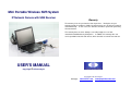
1
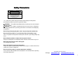
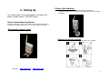
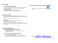
Mini Portable Wireless NVR System
IP Network Camera with USB Receiver
Warranty
The warranty is for one year from the date of purchase. During the one-year
warranty period, the product is eligible for replacement in case of defects in material
and workmanship. In such cases, the defective unit will be repaired or replaced by
the manufacturer.
This warranty does not cover damages caused by improper use or from
unauthorized modifications by third parties. In addition, this warranty does not
cover expendable materials and defects, which constitute as normal wear and tear.
USER’S MANUAL
Copy Right © IA Technologies
Copy Right © IA Technologies
Webpage : www.iat101.com ; www.peephole-store.com
Federal Communication Commission Interference Statement
This equipment has been tested and found to comply with the limits for a Class B
digital device, pursuant to Part 15 of the FCC Rules. These limits are designed to
provide reasonable protection against harmful interference in a residential
installation.
The antennas used for this transmitter must be installed to provide a separation
distance of at least 20 cm from all persons and must not be co-located or operating in
conjunction with any other antenna or transmitter.
This equipment generates, uses and can radiate radio frequency energy and, if not
installed and used in accordance with the instructions, may cause harmful
interference to radio communications. However, there is no guarantee that
interference will not occur in a particular installation. If this equipment does cause
harmful interference to radio or television reception, which can be determined by
turning the equipment off and on, the user is encouraged to try to correct the
interference by one of the following measures:
. Reorient or relocate the receiving antenna.
. Increase the separation between the equipment and receiver.
. Connect the equipment into an outlet on a circuit different from that to which the
receiver is connected.
. Consult the dealer or an experienced radio/TV technician for help.
FCC Caution: To assure continued compliance, any changes or modifications not
expressly approved by the party responsible for compliance could void the user's
authority to operate this equipment. (Example - use only shielded interface cables
when connecting to computer or peripheral devices).
FCC Radiation Exposure Statement
This equipment complies with FCC RF radiation exposure limits set forth for an
uncontrolled environment. This equipment should be installed and operated with a
minimum distance of 20 centimeters between the radiator and your body.
This transmitter must not be co-located or operating in conjunction with any other
antenna or transmitter.
Copy Right © IA Technologies
Webpage : www.iat101.com ; www.peephole-store.com
1
Safety Precautions
Precautions
CAUTION
RISK OF ELECTRIC SHOCK.
DO NOT OPEN!
CAUTION :
TO REDUCE THE RISK OF ELECTRICAL SHOCK,
DO NOT OPEN COVERS (OR BACK).
NO USER SERVICEABLE PARTS INSIDE.
REFER SERVICING TO QUALIFIED
SERVICE PERSONNEL.
** It is advised to read the Safety Precaution Guide through carefully before
operating the product, to prevent any possible danger.
WARNING: This symbol is intended to alert the user to the presence of un-insulated
“dangerous voltage”.
CAUTION: This symbol is intended to alert the user to presence of important
operating and maintenance (Servicing) instructions in the literature accompanying
the appliance.
Do not Plug and unplug the power cord, it may result product malfunction.
Do not install the product in an environment where the humidity is high.
Unless the product is waterproof or weatherproof, otherwise poor image quality may
occur.
Do not drop the product or subject them to physical shocks.
Except for vandal-proof or shockproof product, otherwise malfunctions may occur.
Never keep the product to direct strong light.
It can damage the product.
Do not spill liquid of any kind on the product.
If it gets wet, wipe it dry immediately. Alcohol or beverage can contain minerals that
corrode the electronic components.
Do not install the product in extreme temperature conditions.
Use the camera under conditions where temperatures are ventilation when operating
under high temperatures.
Copy Right © IA Technologies
Webpage : www.iat101.com ; www.peephole-store.com
2
About This Manual
This manual is designed to assist users to operate the Wireless IP USB Camera –
NVR (read carefully). Information in this document has been carefully checked for
accuracy; however, no guarantee is given as to the correctness of the contents.
The information contained in this document is subject to change without notice
1-- Getting started
Congratulations on your purchase of the network camera system. Use this system
to monitor locations wireless, as stand-alone solution.
Checking the packing list
Table of Contents
Safety Caution……………………………………………………………………2
1- Getting Start…………………………………………………………..……….3
Checking the Packing List……………………………………………...…3
USB Receiver……………………………………………………………4
Camera…………………………………………………………………...4
PC System Requirements…………………………………………………4
2- Setting Up………………………………………………………………………5
Camera………………………………………………………………………5
Positioning the Camera…………………………………………………5
Power Supply…………………………………………………………….6
USB Receiver……………………………………………………………….6
Fine Tuning…………………………………………………..…...………6
Installing Supplied Software…………………………………………….6
3- Operation…………………………………………………………………….....7
Viewing Page……………………………………………………………….7
Pairing……………………………………………………………………… 8
System Setting…...……………………………………………….….…….9
Remote Monitoring.……………………………………………………....10
Basic Setting……………………………………………………………....10
Image Adjust…………………………………………………………..…...11
Record Setting ……………………………………………………..…......11
Motion Detect……………………………………………………………....14
Alert Setting……………………………………………………................15
Play Back…………………………………………………………..………15
Appendix…………………………………………………………………………..16
Cleaning.………………………………………………………….……….16
Troubleshooting.…….……………………………………...…………….16
Technical Specification………………………….………….…………….16
Carefully unpack the network camera system and check the following items are
included:
Wireless Camera x 1
USB Receiver x 1
Mounting Bracket x 1
Switching Power Adaptor 5V DC 1A x 1
1.5m USB Extension Cable x 1
NVR software/ User’s Manual CD ROM x 1
Copy Right © IA Technologies
Webpage : www.iat101.com ; www.peephole-store.com
3
Identifying Parts
PC System Requirements
Refer to the following section to identify components of the camera and receiver.
USB Receiver
CPU: Pentium 1.6 GHz or higher (recommended)
RAM: 512 MB or higher (recommended)
Network: Ethernet Port
Resolution: 800 x 600 or 1024 x 768 (recommended)
Operating Software: Windows 2000, XP, Vista or Window 7
Windows Media Player 9 or higher (recommended)
One available USB port
CD-ROM Drive (For software installation)
Noun Definition
•IP Address Setting (IP Assignment): Camera Network Connection
•Account: PPPoE Account
•Password: PPoE Password
•Video Port: Remote Video Port
•Audio Port: Remote Audio Port
Wireless Camera
1 Chain hole
6 Power On/Off
2 Microphone
7 Pairing Button
3 Camera
8 LED Indicator
4 Mounting Socket
9 DC IN
5 Foldable Stand
10 Antenna
Copy Right © IA Technologies
Webpage : www.iat101.com ; www.peephole-store.com
4
2-- Setting Up
- Ceiling / Wall installation
. Fix the camera to the wall or ceiling using the bracket supplied.
. The bracket used must fit securely in the mounting socket to ensure proper
installation.
This section explains the mounting options and setup of the
wireless network camera – USB NVR system.
Wireless Camera Mounting Options
Using the supplied accessories, the camera can be placed on the platform,
mounted on a ceiling or wall, It also can be stuck in a discreet location.
- Put down the camera’s stand
The camera can be placed on a platform.
- Sticking in a discreet location
Stick the camera to a discreet location using the Blue -Tack supplied.
Webpage :
www.iat101.com ; www.ia-tecs.com
5
Power Supply
3. Click “Finish” to complete the software installation.
- Connect the Power Adapter
Connect one end of the AC adapter to the DC IN jack of the camera the other
end to the wall outlet. Make sure power plug is pushed all the way in.
- Battery Recharge
When the software is well installed, you can find
desktop.
on the
The charging starts when the LED turns red. Charging is
finished when the LED turns off (after approx. 4 hours max.)
USB Receiver Setup
There is a driver / NVR software (WUSB Camera) CD in the package. Install
the WUSB Camera software before inserting the USB Receiver into one USB
port of PC.
Make sure the OS of PC is in line with requirements.
Fine Tuning
- Adjust the camera’s viewing angle according to the illustrations.
- Move the camera to make adjustment.
- To keep the USB receiver position above the desktop for best result. You can
connect USB receiver to the USB extension cable supplied to adjust the position
of USB receiver.
Installing supplied software
1. Insert CD-ROM with supplied software.
The setup menu will start.
• Double-click “My Computer” on the desktop, double-click “set up”,
install the software on C:
2. Click on the “Recommended Installation”.
•All necessary software will be installed.
•Only the software compatible with the PC in use will be displayed.
•Proceed with installation according to messages appearing on the screen.
Copy Right © IA Technologies
Webpage : www.iat101.com ; www.peephole-store.com
6
3-- Operation
:
:
Viewing Page
This icon indicates that the camera is monitoring
This icon indicates that the camera is in standby mode
:
:
Insert the USB Receiver to one USB port of PC and double-click
This icon indicates that the camera is recording
This icon indicates that the camera’s audio is enabled
on the desktop, the viewer screen will display as shown below
Main Screen
3.
Option Menu:
4.
This area allows you to do the following:
Snapshot: Built-in snapshot function allows user to capture
images they would like
Detect: Controls the view to go into detection mode or standby
mode
Web Server: Enables web server mode for remote viewer
Setup: This system built-in web interface offers more advanced
settings. On the viewing page, click the SETUP icon to enter
server settings page. It is a toggle button to switch between config
and view pages.
Playback: Enters the playback mode to view recorded videos
Camera/Screen Control:
:
:
:
:
then turn on the camera.
1.
Monitoring Screen:
This will display the camera’s view.
Depending on the configuration, you can have different type of viewing
methods on this screen.
2. Channel Status: This will display the status of each individual
camera.
This area controls the following:
Displays the signal strength of wireless cameras
Cruise camera to let it automatically move on its own
Opens the snapshot folders to view captured pictures
Adjusts the screen size on the monitoring screen
:
Displays one channel on the monitoring screen
:
Displays multiple channels on the monitoring screen
:
Cycles the camera to see all area
Copy Right © IA Technologies
Webpage : www.iat101.com ; www.peephole-store.com
7
5.
Channel Information:
Displays the current channel’s information
Pairing
1. Make sure the camera is turned on, the power LED of the camera will
Blink if it is power on.
2. Click
for match setting, select a camera which you want to match, then
press and hold the pairing button on the side of the camera for about 6
seconds. If the pairing is successful, you can find “Match complete a
camera had been connected.” on the screen as shown below.
4.
3
Press
According to the previous method, to set cameras on other channels.
The monitor will display quad-view window as shown below.
for full view on the screen as shown below
8
System Setting
Press “web server” icon of the main screen to enter “System Setting”.
This section covers the main setup of the network camera system
6. Web Service: Configuration settings for the web server
Network status such as current IP and related details are clearly shown.
IP address: The IP address of the web service for the viewer
This system will log automatically the IP location of where
the current computers. If you use a router or dynamic IP,
refer to note 2 and 3.
Web Server Port: The port for the web service
Web Server Account: Default is “user”
Web Server Password: Password for the web service
You can set password, which is changeable
MMS Server Port: The port for the MMS service
MMS Server Channel: The channel for the MMS service
Select Enable for MMS function
Note: If you require a dynamic IP, you will need to configure your network to
allow access to your camera. First you will need to open the required port for
the computer attached to the camera (default port: 7788). You will then need
to configure you dynamic IP to forward correctly to your external IP address.
We recommend using the service offered by dyndns
(http://www.dyndns.com/support/kb/dvrs.html). Once your hostname has
been configured, install the update client software
(http://www.dyndns.com/support/clients/).
1. Language Support: Changes the interface of the system to the
language selected
2. Mail Server: The mail server settings for users who wish to use the
e-mail notification when detection occurs
3. Start Up Options: Allows user to pre-determine start up options
including:
Start Detecting: Starts the viewer in detection mode
Start Web Server: Starts the viewer web server
4. Recurring Recording: Tick Enable, to records over older files to save
space for the hard disk
5. Record: Locations of where the files are being saved for recorded
videos and captured images. If it appears “Path of save to file not
exist”, you have to click both Default at the Record and Snapshot.
Copy Right © IA Technologies
Webpage : www.iat101.com ; www.peephole-store.com
9
Remote Monitoring
When the correct IP address is set in the web service, press “web server” icon of
main screen; then open the IE or Mozilla Firefox browser to input http://IP
address:7788, will appear the below dynamic image; or input mms://IP
address:8080 on mobile phone, which has mms features, can monitor this image
as well as shown below.
1. Input http://IP address:7788/
2. Display dynamic image of video channel
3. Indicates the disk total capacity and available capacity
Copy Right © IA Technologies
Webpage : www.iat101.com ;
www.peephole-store.com
Basic Settings
This section of the wireless network camera system viewer allows users to
display custom information on the main screen.
Channel: Defines a personal name and description of the camera
Text Display: Allows customization of what information can be displayed on
the channel’s screen
Channel Information: Check it to show channel number and/or channel
name
Date and Time: Check to show date, time, and/or week
Font Size: Adjusts the size of the font being displayed
Text color: The text’s color on the screen
Background: The text’s background color on the screen
Watermark: Check for attaching a watermark image on the screen
10
Image Adjust
Record Setting
If the camera is mounted in a special way, the section can adjust the image
accordingly.
This section sets up how recording will be performed under recording mode.
Choose from the following to adjust image:
Image Quality: Adjust the quality of the recording format
Flip Horizontal: Flips the image horizontally
Select the icon of “Flip Horizontal”, and then display the flip dynamic image
Flip Vertical: Flips the image vertically
Select the icon of “Flips Vertical”, and then display the flip dynamic image
Rotate: Rotates the image accordingly with rotation angle and direction
Select the icon of “rotate”, and the next, “Counter-Clockwise\clockwise”,
then fine tune the rotation angle, and then display the rotate dynamic
image.
Source Adjustment
Adjust video parameters to process brightness, saturation and gamma
Resolution: Adjust the recording image size
Quality: How detailed the recording of the image
Surveillance Mode: Adjusts the type of recording it would be trigged with
First Selection Details:
- Schedule: Will go into detection mode and record on user’s configured
schedule
-Record-at-click: Once in detection mode, it will record in either full time
or on detection
- Non-record: Will record a time frame when viewer detects movement
11
Schedule Base: If “Schedule” is chosen from mode, user can preset a
Select Daily
time to record.
Add new Schedule: To add a schedule
Select the icon “recording”, and click “Add new Schedule”, then appear the
below images
Select Periodically
1. Setup the start time of Scheduling Type “daily”
2. Setup the end time of Scheduling Type “daily”
3. Select the icon “Operative Period” to specific period
1. Setup the start date and time of Scheduling Type “Periodically”
2. Setup the end date and time of Scheduling Type “Periodically”
Copy Right © IA Technologies
Webpage : www.iat101.com ; www.peephole-store.com
12
Select Weekly
1.
2.
3.
4.
Choose the start time of Scheduling Type “Weekly”
Choose the end time of Scheduling Type “Weekly”
Select the icon “Operative Period” to specific period
Select the icon to setup weekday of weekly Scheduling
Select Monthly
1.
2.
3.
4.
Choose the start time of Scheduling Type “Monthly”
Choose the end tine of Scheduling Type “Monthly”
Select the icon “Operative Period” to specific period
Select the icon to setup month day of monthly scheduling
Edit Schedule: To edit an existing schedule
Delete Schedule: Deletes a selected schedule
Copy Right © IA Technologies
Webpage : www.iat101.com ; www.peephole-store.com
13
Motion Detect
a. Full-area detection: Detects all areas on the screen
This section will be available if the recording is set to “Triggered”, this particular
area allows users to customize sections of detection and the sensitivity.
Display Screen: Hit the “Refresh View” button to refresh the image
Detection Settings: Allows custom areas to detect on the displayed screen
b. Custom detection: Detects user created detection blocks
Add new area: Select the icon “Add new Area” to add new area
to detect, do this by holding down the right mouse button over the
displayed screen area to create a new block.
Delete Area: Select a block on the displayed screen and hit this
button to delete it
Delete All Areas: Deletes all blocks on the displayed screen
Test Detection: Test the detection by moving an object in front of
the camera, the blocks should change color when it detect motion
c. Sensitivity: Adjust the sensitivity of the detection
Copy Right © IA Technologies
Webpage : www.iat101.com ; www.peephole-store.com
14
Alert Setting
This section will be available if the recording option is set to “Triggered”, this
particular area allows the user to set notification options in the even the viewer
detects motion.
e. Vibration alert: When enabled, it vibrates the whole viewer when motion is
detected
f. Message alert: When enable, it prompts a message alert on viewer when
motion is detected
g. Sound alert: When enabled it will playback the chosen sound when motion
is detected
h. E-mail alert: When enabled, a message will be sent based on the
information filled out
1. Main display screen: This area will display the video output from the recording
2. Intelligent search: not available
3. Time and channel selection: This filters out when and which channel to be
listed in the “Record List”, click the “Query” button to bring up the list once
selected the proper times and channel
4. Record list: This area is where you choose the video and have the option to
delete it and open the file directory of your videos
5. Video tracker: Use this to track through your video
6. Playback controls: (Front left to right)
. Play /Pause
. Stop
. Previous track
. Rewind
. Fast forward
. Next track
Playback
This section allows users to playback and search through the recorded videos
Press the “Playback“ on the main screen
. Playback speed (1x, 2x, 4x, 8x, 16x)
7. Capture options: Use the camera to capture a picture on the main display
screen and use the folder to access the captured pictures.
15
bad network setup, make sure that your network is configured correctly.
Appendix
This appendix describes cleaning and troubleshooting procedures.
covered are technical specifications, and warranty information.
Cleaning
The lens can be wiped with a soft optical cleaning cloth.
be cleaned with glass cleaner.
Also
The dome cover can
Troubleshooting
If you experience problems operating the wireless network camera – usb nvr
system, make sure that you have tried the list of procedures in this section before
you contact your distributor.
Why are some of the camera and/or screen control not accessible?
Some of the controls can only be accessed when in single screen mode.
Also, you’ll need to be out of the detection mode in order to access them
as well.
Why can I not access the settings and playback?
You need to be out of detection mode in order to access these settings.
I don’t have static IP address, can I used DDNS?
This program supports DDNS, but you can still access it through IP
address or DNS address.
Why does the viewer not start recording after going into detection mode?
Double check the channel’s recording setup. Make sure that the
recording options you set are the correct ones. If it’s full-time, it should
record all the time. If triggered, it will record only when camera detects
movement.
When I enabled the web server, I can’t preview the image of the camera
from other PCs.
Please check if the local area connection has the firewall blocking that
particular program and that the IP address is correct.
What does “Can not connect to following channel(s): CH**” mean?
It means the viewer can not detect the IP camera. It could be caused by a
What does “Can not import to the following channel(s): CH**” mean?
It means that another web server is conflicting with another IP address.
Double check your IP address assignment on all your network devices.
What does “No buffer space error” and “Virtual RAM insufficient” mean?
It means your computer is running low on resources (typically means that
your RAM is insufficient). Upgrading your memory will most likely address
this issue. Again, we strongly recommend systems to be equipped with 1
GB of RAM
Technical Specifications
Frequency
Antenna
Modulation
Spread Spectrum
Image Sensor
Lens
Anti Interference
Data Rate
Frame Rate
Channel Bandwidth
Format
Dimensions
Weight
Power
Operating
temperature
2.4 GHz
Chip Dielectric
GFSK
FHSS
1/5 inch sensor
F/ 2.0, diagonal: 63.3 degrees
Clean Channel Dynamic Select
1.3 Mbps
1CH - 10 ~15 fps, VGA 640 x 480
4CH - 15~20 fps, QVGA 320 x 240
2MHz
Wmv (Video), JPG (Photo)
Camera: 70 x 40 x 20mm ( L x W x H )
Receiver: 68 x 24 x 11mm ( L x W x H )
Camera (ACT-867 T): 58g (including battery)
Receiver (ACT-867 R): 15g
DC 5V 1A; Power Adapter
Rechargeable Li-ion Battery
-10℃ ~ 50℃
16
Edition
1st Edition
Copyright
This publication contains information that is protected by copyright. No
part of it may be reproduced, transmitted, transcribed, stored in a retrieval
system, or translated into any language without permission from the
copyright holders.
Copyright © 2
All rights reserved
WEEE Directive & Product Disposal
.
At the end of its serviceable life, this product should not be treated as
household or general waste. It should be handed over to the
applicable collection point for the recycling of electrical and electronic
equipment, or returned to the supplier for disposal.
THIS DEVICE COMPLIES WITH PART 15 OF THE FCC RULES. OPERATION IS SUBJECT TO
THE FOLLOWING TWO CONDITIONS:
(1) THIS DEVICEMAY NOT CAUSE HARMFUL
INTERFERENCE AND (2) THIS DEVICE MUST ACCEPT ANY INTERFERENCERECEIVED,
INCLUDING INTERFERENCE THAT MAYCAUSE UNDESIRED OPERATION.
Copy Right © IA Technologies
Webpage : www.iat101.com ; www.peephole-store.com
17