1
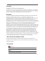
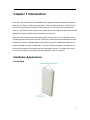
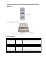
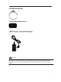
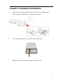
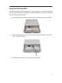
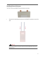
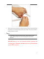
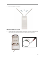
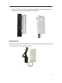
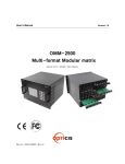
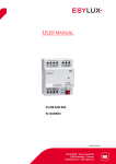
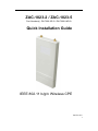
ZAC-1023-2 / ZAC-1023-5
Part Number(s): ZN-7200-2EI-O / ZN-7200-2AEI-O
Quick Installation Guide
IEEE 802.11 b/g/n Wireless CPE
Version: 0.5
1
Copyright
Copyright © 2015 Zcomax Technologies, Inc.
All rights reserved. No part of this publication may be reproduced, distributed, or transmitted in
any form or by any means, including photocopying, recording, or other electronic or mechanical
methods, without the prior written permission of Zcomax Technologies, Inc.
Disclaimer
THE SPECIFICATIONS AND INFORMATION REGARDING THE PRODUCTS IN THIS MANUAL ARE
SUBJECT TO CHANGE WITHOUT NOTICE. ALL STATEMENTS, INFORMATION, AND
RECOMMENDATIONS IN THIS MANUAL ARE BELIEVED TO BE ACCURATE BUT ARE PRESENTED
WITHOUT WARRANTY OF ANY KIND, EXPRESS OR IMPLIED. USERS MUST TAKE FULL
RESPONSIBILITY FOR THEIR APPLICATION OF ANY PRODUCTS. THE SOFTWARE LICENSE AND
LIMITED WARRANTY FOR THE ACCOMPANYING PRODUCT ARE SET FORTH IN THE INFORMATION
PACKET THAT SHIPPED WITH THE PRODUCT AND ARE INCORPORATED HEREIN BY THIS
REFERENCE. IF YOU ARE UNABLE TO LOCATE THE SOFTWARE LICENSE OR LIMITED
WARRANTY, CONTACT YOUR ZCOMAX REPRESENTATIVE FOR A COPY. NOTWITHSTANDING ANY
OTHER WARRANTY HEREIN, ALL DOCUMENT FILES AND SOFTWARE OF THESE SUPPLIERS ARE
PROVIDED “AS IS” WITH ALL FAULTS. ZCOMAX AND THE ABOVE-NAMED SUPPLIERS DISCLAIM
ALL WARRANTIES, EXPRESSED OR IMPLIED, INCLUDING, WITHOUT LIMITATION, THOSE OF
MERCHANTABILITY, FITNESS FOR A PARTICULAR PURPOSE AND NONINFRINGEMENT OR
ARISING FROM A COURSE OF DEALING, USAGE, OR TRADE PRACTICE IN NO EVENT SHALL
ZCOMAX OR ITS SUPPLIERS BE LIABLE FOR ANY INDIRECT, SPECIAL, CONSEQUENTIAL, OR
INCIDENTAL DAMAGES, INCLUDING, WITHOUT LIMITATION, LOST PROFITS OR LOSS OR DAMAGE
TO DATA ARISING OUT OF THE USE OR INABILITY TO USE THIS MANUAL, EVEN IF ZCOMAX OR
ITS SUPPLIERS HAVE BEEN ADVISED OF THE POSSIBILITY OF SUCH DAMAGES.
About the Quick Installation Guide
This Quick Installation Guide is intended to guide professionals in the installation and
configuration of the ZAC-1023 series CPE. It covers procedures that will assist you in avoiding
unforeseen problems.
Conventions
Warning:
This sign indicates a warning or caution.
Note:
This sign indicates an important note.
2
Chapter 1 Introduction
Zcomax’s ZAC-1023 series of 2x2 MIMO CPE’s support multiple operational modes in
either the 2.4 GHz or 5 GHz frequency band. These models also come with Zcomax’s
Virtual Access Controller firmware, which offers a low cost zero-touch management
solution. The ZAC series is suitable for small business and large enterprise wireless ISP
applications where multiple network devices are required.
What truly sets this wireless LAN solution apart from the others is its versatility. When
operating as an access point, the ZAC-1023 can provide centralized management and
monitoring of all the managed Aps on the network without the additional expense of a
separate WLAN controller. Additionally, The ZAC-1023 series can be configured as a
point-to-point bridge, solving last mile communications needs. This product is truly an
out of the box solution requiring minimal knowledge or skill to configure.
Hardware Appearance
Front View
3
Back View
Inside the Bottom Cover
LED Indicators
LED
COLOR
STATUS
DESCRIPTION
PWR
Green
On
The device is powered on
Off
The device is not receiving power
On
The device has Ethernet connection
Off
The device has no Ethernet connection
Blinking
Transmitting/receiving data
On
The W LAN is active
Off
The W LAN is inactive
Blinking
Transmitting/receiving wireless data
3 LED On
Excellent signal strength
2 LED On
Good signal strength
1 LED On
Weak signal strength
LAN
WLAN
Signal*3
Green
Green
Green
4
Chapter 2 Installation Safety Precautions
Here are extremely important safety factors to consider. Learning and following simple safety
precautions can quite literally save your life. Following safety procedures also helps prevent costly
damage to your equipment and property.
No list of safety guidelines can cover every potential hazard. Consequently, careful planning,
common sense, and good judgment must be used at all times.
1. Locate and avoid power lines and other wires in the work area.
2. Do not climb on a wet or icy roof. Do not attempt high installations on windy days.
3. Do not position ladders at angles steeper than 70˚.
4. Dig the base of the ladder into the ground if possible.
5. Do not climb on roofs that have curled or worn shingles. (Old shingles break easily or pull out.)
6. Wear clothing that is not too tight or too loose. Wear rubber soled shoes or boots.
7. Carefully survey the job before beginning the installation to locate secure handholds,
dangerous conditions (such as power lines and weak roofs), and the safest and most convenient
placements for ladders.
8. Do not climb onto a roof when there is no one else around. Be sure all of your helpers know
and follow safe procedures.
9. Do not install antennas under large, over- hanging tree branches if it can be avoided.
10. Antennas must be installed away from power lines at a distance equal to at least twice the
combined length of the mast and antenna. Thoroughly plan every installation. Carefully think
through the job, and don’t take dangerous shortcuts.
5
Installation Precautions
Zcomax recommends following these precautions while installing your ZAC-1023
series CPE.
1. Do not touch or move the antenna while the unit is transmitting or receiving.
2. Do not hold any transmitting antenna or radio-containing component close to
any exposed parts of the body, especially the face or eyes.
3. Do not operate the radio or attempt to transmit data unless the antennas are
connected; otherwise, the radio will be damaged.
4. Use a good known ground and power surge protector, all outdoor installations
are subject to lightning and power transients.
• ESD (Lightning) DAMAGE IS NOT COVERED UNDER WARRANTY.
Installers MUST use the manufacturer’s power supply & POE injector shipped
with the ZAC-1023 series, or the radio will be damaged and warranty voided.
Product Package
The package you received should contain the following items. If any item is missing or
damaged, please contact your vendor for support.
IEEE 802.11n ZAC-1023 CPE
X1
Detachable 5dBi antennas
X2
Pole Mounting Ring
X2
24 VDC POE Injector
X1
AC Power cord
X1
Ferrite Suppression Core
X1
Grounding Wire
X1
Product CD
X1
Note:
Product CD contains the Quick Installation Guide and User Manual.
6
Pole Mounting Ring
Ferrite Suppression Core
24VDC Power Cord & POE Injector
Warning:
Installers MUST use the manufacturer’s power supply & POE injector shipped with the ZAC1023 CPE, use of a non-factory approved power supply will destroy the device and void the
warranty.
7
Chapter 3 Hardware Installation
1.
The bottom of the ZAC-1023 CPE has a removable cover. Remove the
retaining screw and slide the cover off as shown below.
2.
Insert an Ethernet cable from the POE into the RJ45 port.
3.
Slide the cover back to seal the bottom of the ZAC-1023.
8
Using the Grounding Wire
The ZAC-1023 series CPE is equipped with a grounding wire. It is important that both
the CPE and POE Injector are properly connected to earth ground during normal use
to protect against surges or ESD.
1. Remove the screw on the ground terminal point at the bottom of the ZAC 1023.
2. Put the grounding wire on the grounding terminal at the bottom of the ZAC
1 0 2 3 . Tighten the screw.
3. Connect the ground wire to a good known earth ground.
9
Installing External Antennas
The ZAC 1023 has two SMA-RP external antenna connectors.
1.
Connect the included external antennas to the SMA-RP connectors on top of the
CPE.
Warning:
Installers MUST power off the ZAC 1023 before connecting the external
antennas. Do not power on the device without the antennas attached. Doing so will
damage the unit.
10
2.
Tighten the antenna connectors by turning clockwise. Zcomax recommends fixing
one antenna in a horizontal position and the other vertical. This will give 30 dBi of
isolation between the radios.
Note:
The polarization of antennas should be properly aligned. Maximum signal
strength between bridges occurs when both bridges are using identical
polarization.
DO NOT bend or turn the antennas without loosening the
connector joint. Otherwise, damage may occur to the antennas
and/or SMA terminals .
11
3
Antenna installation is complete.
Mount the CPE onto a Pole
1.
Unlock each pole mounting ring with a screwdriver. Slide each ring through the
two mounting foot channels located on the back of the unit as shown.
12
2.
Mount the ZAC 1 0 2 3 to the antenna mast; tighten hose clamps firmly. Overtightening the screws will damage the mounting foot.
Powering Up
Connect the power cord to the POE injector. Connect an Ethernet cable from the CPE
to the “Data & Power Out” port of the Injector.
13
Connecting the ZAC-1023 to your Network
Follow these instructions for configuration and management:
1.
Open the ferrite core by unsnapping the connector latches. The core will open,
revealing a concave surface.
2.
Lay the Ethernet cable into the core, usually within 2 to 3 inches of the
connector. You may have to experiment with the final location depending on the
effectiveness of the high frequency abatement.
3.
Loop the cable around and through the core. This may be required in
circumstances with severe interference.
14
4.
Close the core and snap the assembly back together.
5.
Insert the Ethernet cable into the “Data In” port of the POE injector.
6.
Connect the Ethernet cable to a PC, switch or hub.
15
7.
Plug the power cord into an A/C power outlet. The unit will immediately
boot. You can begin the device configuration described below.
Note:
The Ethernet port on the ZAC-1023 series is auto configured. There is no need for
cross-over cabling.
16
Chapter 4 Configuration
1.
Connect the ZAC-1023 CPE to your PC with an Ethernet cable, plugged into the
LAN port of the POE injector.
2.
Assign a static IP address to your PC’s TCP/IP IPv4 Properties. It should be in the
same subnet as the ZAC-1023. The default IP address is 192.168.1.1, so you
may choose from 192.168.1.2 ~ 192.168.1.254. Use a Class-C subnet mask. No
default gateway configuration is needed.
17
3. Open the web browser on your PC, type in the d e f a u l t IP address
(192.168.1.1) of the ZAC-1023 CPE in the address bar, and then hit Enter.
4. Enter the default username and password on the log-in w e b page of the ZAC
1 0 2 3 Access Point. The defaults are “admin” and “password.” Click Login.
Configuring ZAC-1023 Operation Mode
The ZAC-1023 CPE is a versatile wireless networking device supporting multiple
operational modes. This quick installation guide covers; “Thin AP mode”, “AC+Thin AP
mode”, and “FAT AP mode”. For further information covering operational modes not
discussed here, refer to the user’s manual.
18
Virtual Access Point Controller Mode
To operate as AC + Thin AP, go to Basic Settings. From the Device Mode drop-down
list, select “Virtual AC” mode. If you would like the Access Point to perform as a
virtual controller and access point concurrently, select “Virtual AC + Thin AP” mode.
Then assign an IP address to the ZAC-1023 CPE and specify subnet mask, gateway,
and DNS addresses respectively. Click Apply. It will take approximately 50 seconds for
the change to take effect.
Note:
AC + Thin AP mode allows the ZAC 1023 CPE to operate as access controller and thin AP
concurrently.
19
For Virtual Controller + Thin AP mode, you will need to configure the SSID and
encryption method settings for the ZAC-1023 CPE. Go to Wireless Settings >
Wireless Networks and click on #1 Wireless SSID for configuration. After the
configuration is made, click Save.
The ZAC-1023 will allow you to configure up to 8 virtual networks and encryption levels.
20
A dialog message will pop up to confirm the changes. Select Apply to save the
values to all the managed Thin APs.
To make profile settings on the ZAC-1023 VAP controller take effect, you will need to
reboot. Go to Management > Configuration File and click the Reboot button. The
process will take approximately 50 seconds to complete.
21
Firmware Upgrade for ZAC-1023 in AC Mode
To upgrade the firmware for the ZAC-1023 in AC mode, go to Management >
Firmware Upload and select Upgrade AC Firmware, then browse to the location of
the firmware file on your computer. Hit Upload to start the upgrade process. It will
take approximately 2 minutes to complete.
Install the Managed Thin AP
Install and connect the rest of the managed ZAC-1023 CPEs in your network via
Ethernet cables. When powered on, they will automatically discover the ZAC-1023
controller and register themselves to the network.
22
To verify if the thin APs have been successfully registered, enter the web page of the
ZAC 1023 Access Point master access controller and go to Management > AP
Management. You will see “Registered” in the Status column. Besides registration
status, other information is available; such as the device name, MAC address, IP
address, FW version, the number of clients that associate to each thin AP, and
upload/download speed.
Moving the mouse over t h e MAC address of each managed AP will display
relevant RF information such as channel mode, current channel, the type of antenna
being used, and transmit output power.
23
Configure and Manage Thin APs:
Enter the web page of the ZAC Access Point in AC mode and go to Management
> AP Management.
The configured AP in Virtual AC + Thin AP mode is highlighted in bold on the list.
By selecting it and hitting the Radio button, you can configure the channel
bandwidth, channel antenna, and output power.
AP Management also allows you to reboot the managed AP, change its IP address,
and perform firmware upgrades.
24
Firmware Upgrade for Managed Thin APs
For firmware upgrades, you may choose to upgrade the selected Thin AP by clicking
Upgrade Selected or the entire group by clicking Upgrade All. First you need to locate
the new firmware for the ZAC-1023 CPE. Go to Management > Firmware Upload,
browse the firmware file location on your PC, click Upload and OK.
When this window appears, you have successfully updated your firmware.
You can now go back to Management > AP Management for a single or
group update.
25
Monitor Managed Thin APs
To view each managed CPE’s status, go to Status > Managed Aps. Here you can
view device information: CPE Name, MAC address, IP address, and Firmware version.
You can also monitor the wireless CPEs that are currently associated with the managed
VAP along with transmission and packets statistics.
Configuring Fat AP mode
The Fat AP mode is used for to configure ZAC-1023 series CPE as;
1. A single access point, wireless gateway.
2. A Wireless Client / Station.
3. A P2P (Point 2 Point) bridge.
4. A P2MP (Point 2 Multi Point)
26
Login using the instructions provided earlier. Select the Basic Settings tab, and then
for the “Device Mode” choose Fat AP.
A confirmation window will appear. Click “OK” and the CPE will reboot.
27
If your CPE was previously configured in virtual access mode, it can be switched to Fat
AP mode. Go to Management > System Settings. From the Device Mode drop-down
list, select “Fat AP” and click YES to make the change take effect.
The CPE will write your selection to the firmware, which takes 60 seconds. After the
changes are made, the device will reboot.
The Fat AP covers these modes; “AP”, “Wireless Client”, “Bridge”, and “AP
Repeater.”
28
Setting Networking Parameter
From the Status Page, select SYSTEM, then the Network Settings tab. This will open the
network settings for the Ethernet port on the CPE.
AP Mode
1. Choose Wireless > Basic Settings. The default mode is AP. Here, you
can change wireless parameters such as SSID, operating channel, transmit
output power, etc. After the configuration is made, click Apply to save.
29
Note:
To keep the CPE within the legal transmit power regulations for your country, please enter
known gain value of the antenna(s). The firmware will compensate for that value and adjust
the power levels on the ZAC-1023 CPE.
1.
If security is required, open Wireless > Profile Settings and click on “Profile 1”
as shown below.
30
2.
You may configure parameters such as “Network Authentication” and “Data
Encryption” for more secure network communication. After the configuration is
made, click Apply to save.
To improve data transmission at long distances, the ZAC-1023 CPE can automatically
adjust proper ACK timeout values by specifying t h e distance between the nodes. To
set the distance, go to Wireless > Advanced Settings and e n t e r the value in the
Distance field. If the distance is less than 1000 meters, leave the field unchange
31
Wireless Client Mode
1. Go to Wireless > Basic Settings and choose “Wireless Client” from Wireless
Mode. Specify the SSID for the Access Point. Then enter the gain of the external
antennas. Click Apply to save the configuration.
2. Besides specifying the SSID manually, you may select a preferred Access Point
to connect to by clicking the “Site Survey” button beside Wireless Mode.
32
3. The wireless client will then scan all the available access points within the
coverage area. Make your selection, then click Select AP to establish the
connection.
4. If the AP you connected to requires authentication or encryption, click Profile
Settings in the left column. Select the corresponding authentication and
encryption options, and click “Apply” to save.
5. To check if the association with the Access Point has been successfully made, go
to Status > Connections. If the connection is established, it will display
association information of the Access Point: MAC address, wireless mode,
signal strength, and connection time.
33
Bridge Mode
1. Go to Wireless > Basic Settings. Choose “Bridge” from Wireless Mode and
choose a clear channel. Next, enter the gain of the external antennas. Click
Apply to save the configuration.
2. Go to “WDS Settings” in “Wireless”, input the MAC address of the
remote bridge i n to the “Remote AP MAC Address 1” field and click “Apply”.
34
Note:
Bridge uses the W DS protocol that is not defined as the standard thus compatibility issues
between equipment from different vendors may arise. Moreover, Tree or Star shape
network topology should be used in all W DS uses-cases (i.e. if AP2 and AP3 are specified
as the W DS peers of AP1, AP2 should not be specified as the W DS peer of AP3 and AP3
should not be specified as the W DS peer of AP2 in any case). Mesh and Ring network
topologies are not supported by W DS and should be avoided in all uses.
3.
Repeat the above procedures to configure the remote ZAC-1023 Bridge.
4.
Enter the actual distance in the Distance field. For example, if the distance
between the two ZAC-1023 bridges is 3 kilometers, enter “ 3000” in the field.
Click Apply to save configuration.
5. Use ping to verify the link between the two bridges.
35
6. To check the wireless connectivity, go to Status > Connections.
If the
connection is established, it will display association information of the remote
bridge, including the MAC address, wireless mode, signal strength, and
connection time.
AP Repeater Mode
Go to Wireless > Basic Settings. Choose “AP Repeater” from Wireless Mode, and
click Apply to save.
To establish a point-to-point bridge connection, please follow the procedures described
in Bridge mode. To connect the wireless client to the AP, please follow the procedures
described in Wireless Client mode.
36