1
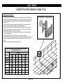
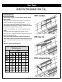
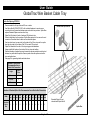
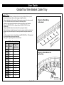
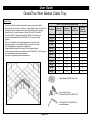
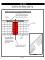
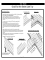
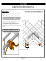
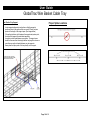
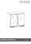
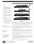
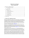
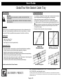
User Guide
GlobalTrac Wire Basket Cable Tray
Safety Information
Cutting Recommendations
WARNING:
DO NOT USE AS A WALKWAY, LADDER, OR SUPPORT FOR
PERSONNEL.
USE ONLY AS A MECHANICAL SUPPORT FOR CABLES, TUBING
AND RACEWAY.
•
•
•
•
•
Intended Use
Install this tray only in a restricted service environment, such as a data center. Use
indoors only, in environmentally controlled areas; do not use outdoors, or in harsh
environments. Allow only qualified service personnel to install or use this tray.
•
Use cable tray cutting tool to cut tray wires. Use side action bolt cutter to
prevent sharp wires from protruding past the cut intersection.
Angle cuts beyond cross wire (See Offset Cut image below).
Concentrate on making smooth, clean cuts to prevent sharp edges.
Cut bottom wires first, in the order shown below, starting the first cut at
1 and continuing in numerical order (see Bottom Cutting Order image).
Cut side wires next, starting at the top and working down (see Side
Cutting Order image).
Examine all cuts and smooth out any sharp edges.
Tools Required
•
•
•
Cable Tray Cutting Tool
10mm Socket Wrench
Sand Paper (for removal of painted finish)
Recommended Tools:
•
•
•
•
•
•
•
•
Any tools needed for mounting the tray should be identified before installation.
A metal file may be used to chamfer rough edges after cutting tray.
Handheld rotary sanding tools speed up paint removal.
Marking tools for marking wire cut locations reduce mistakes and ease planning.
Electric nut drivers reduce assembly time of fittings.
A plumb bob or laser level may be used to verify effectiveness of mounting points.
A level may be used to check consistency of tray runs.
A vacuum may be useful for cleanup of metal and paint shavings.
Offset Cut
(Recommended)
Center Cut Blades are
NOT Recommended
6
5
4
3
1
2
2
1
4
1
3
Available outside of the US and Canada.
Bottom Cutting Order
Side
1
5
1
Cutting
1
6
1
1
Order
84811-GlobalTrac User Manual, 08/20/13, Rev. 1, CPI/PEH MKT-60020-592
+86 21 6880-0266 • www.chatsworth.com.cn
This drawing contains proprietary and confidential information and is protected by U.S. and international law. Unauthorized
reproduction, disclosure or use of the drawing or the information therein is expressly forbidden except as agreed to in writing by
Chatsworth Products, Inc.
Page 1 of 10
User Guide
GlobalTrac Wire Basket Cable Tray
End-to-End Splicing OPTION 1
•
•
•
•
•
•
•
Use Standard Splice Kit (P/N 84738-X01) or Spacer Splice Kit (P/N 84728-X01) to
connect sections of wire mesh cable tray together end-to-end, at intersections and
turns. Spacer Splice Kit includes features to evenly space tray sections together
end-to-end.
Refer to table below for the number of splices required to form an end-to-end
connection. Quantities listed in table are for individual splices.
Use two splices (one per side) on the sides of the 50 mm tray and four splices
(two per side) on the sides of the 100 mm and 150 mm trays; use the rest of the
splices evenly spaced on the bottom of the tray.
The two halves of the splice wrap around adjacent wires on the tray connecting
the tray wires together.
Always install bolt heads on the inside of the tray to protect cables.
Electrical bonding of painted trays and connectors requires metal-to-metal contact
between tray wires and the splice. Remove paint where the splices contact the
trays.
See page 9 for grounding details and instructions.
Number of Standard Splices Recommended to Form an
End-to-End Connection
Tray Width
Height
50
mm
100
mm
150
mm
200
mm
300
mm
400
mm
150 mm
2
N/A
N/A
2
4
N/A
4
5
6
4
6
6
4
6
6
4
7
7
450
mm
500
mm
600
mm
700
mm
800
mm
900
mm
50 mm
4
5
5
5
6
6
100 mm
7
7
8
8
8
8
150 mm
7
7
8
8
8
8
50 mm
100 mm
Page 2 of 10
P/N 84738-X01: Standard Splice
User Guide
GlobalTrac Wire Basket Cable Tray
End-to-End Splicing OPTION 2
•
•
•
•
•
•
•
•
•
STEP 1: Insert Splice
Use Spring Splice (P/N 84834-X01) to connect sections of wire mesh cable tray
together end-to-end.
Refer to table below for the number of splices required to form an end-to-end
connection. Quantities listed in table are for individual splices.
Use two splices (one per side) on the sides of the 50 mm tray and up to four
splices (two per side) on the sides of the 100 mm and 150 mm trays; use the rest
of the splices evenly spaced on the bottom of the tray.
The splice wraps around adjacent wires on the tray connecting the tray wires
together.
Insert splice as shown and use installation tool to pull splice into place.
Ensure that the splice is installed with the middle tab facing in the tray and the flat
edges are facing away from the tray.
The tray will not be stable until splices are installed on both sides of the tray.
Electrical bonding of painted trays and connectors requires metal-to-metal contact
between tray wires and the splice. Remove paint anywhere the splices contact the
trays.
See page 9 for grounding details and instructions.
STEP 2: Align Tool
Number of Spring Splices Recommended to Form an
End-to-End Connection
Tray Width
Height
50
mm
100
mm
150
mm
200
mm
300
mm
400
mm
150 mm
2
N/A
N/A
2
2
N/A
2
2
4
2
2
4
2
4
6
2
4
6
450
mm
500
mm
600
mm
700
mm
800
mm
900
mm
50 mm
4
4
4
4
4
4
100 mm
6
6
6
7
7
7
150 mm
7
7
8
8
8
8
50 mm
100 mm
STEP 3: Lock splice into place
Page 3 of 10
User Guide
GlobalTrac Wire Basket Cable Tray
End-to-End Splicing OPTION 3
•
•
•
•
•
•
•
•
•
Recommended for all trays that are 450 mm or wider
Use Splice Bar Kit (P/N 84739-X01) with included hardware to create a more
secure end-to-end connection between wire mesh cable tray sections. Splice Bars
replace Standard Splices used on side of tray.
Splice Bar Kit includes 3 each of washers, M6 bolts and nuts.
Refer to table below for the number of Splice Bars required to form an end-to-end
connection. Quantities listed in table are for individual splices.
Use two splice bars (one per side) on the sides of the 50 mm tray and four splice
bars (two per side) on the sides of the 100 mm and 150 mm trays.
Splice Bar attaches to the side of the tray using provided hardware.
Always install bolt heads on the inside of the tray to protect cables.
Electrical bonding of painted trays and connectors requires metal-to-metal contact
between tray wires and the splices. Remove paint where the splices contact the
trays and splice bars.
See page 9 for grounding details and instructions.
Included with Splice Bar Kit
Number of Splice Bars
Recommended for an
End-to-End Connection
Height
Splice
Bars
50 mm
2
100 mm
4
150 mm
4
Number of Standard Splice Kits Recommended for an End-to-End Connection
Width
Standard
Splice
Kits
50
mm
100
mm
150
mm
200
mm
300
mm
400
mm
450
mm
500
mm
600
mm
700
mm
800
mm
900
mm
1
1
2
2
2
3
3
3
4
4
5
5
Page 4 of 10
Standard Splice Kits not
included with Splice Bar Kit
Splice Bar
User Guide
GlobalTrac Wire Basket Cable Tray
o
Smooth 90 Turn
• Refer to the table below to determine how many tray sections will be required to
be cut from the tray for the turn (See images on right for detail).
• Refer to table below for the number of hardware pieces required to form a smooth
90° turn. Quantities listed in this table are for individual splices.
•
Make one splice connection between each removed section. Use Standard
Splice Kits (P/N 84738-X01) or Spacer Splice Kit (P/N 84728-X01) for the
connections.
• Always install bolt heads on the inside of the tray to protect cables.
• Electrical bonding of painted trays and connectors requires metal-to-metal contact
between tray wires and the splice. Remove paint where the splices contact the
trays.
• Installing a ground conductor along fitting using P/N 84838-001 or -002 is required
to ensure bonding across removed sections.
• See page 9 for grounding details and instructions.
50mmH x 300mmW tray
before bend
Smooth 90° Turn Forming Guide
Tray
Width
Removed
Sections
P/N 84738-X01
or
P/N 84728-X01
50 mm
1
1
100 mm
2
2
150 mm
3
3
200 mm
4
4
300 mm
6
6
400 mm
7
7
450 mm
8
8
500 mm
10
10
600 mm
11
11
700 mm
12
12
800 mm
13
13
900 mm
14
14
50mmH x 300mmW bent and
spliced tray
P/N 84738-X01:
Standard Splice Kit
Page 5 of 10
User Guide
GlobalTrac Wire Basket Cable Tray
Tight 90° Turn
•
•
•
•
•
•
Refer to the table to the right to determine how many tray sections will be
required to be cut from the tray for the turn. Ensure that the side wire cuts and the
mid-section cuts are always symmetric (See cutting detail on the next page).
Bend the tray 90° around the center of the cuts. Use the 90° Splice Bar
Kit (P/N 84740-X01), Clamp Washer Kit (P/N 84746-X01) and bolt and
nut from the Standard Splice Kit (P/N 84738-X01) to secure the fitting
together.
Use the 90° Splice Bar with provided hardware to connect the inside
side edges together. Use the Clamp Washers, bolt and nut to clamp
the over-lapping mesh together (See image below).
Always install bolt heads on the inside of the tray to protect cables.
Installing a ground conductor along fitting using P/N 84838-001 or -002 is required
to ensure bonding across removed sections.
See page 9 for grounding details and instructions.
Tight 90 ° Turn Forming and Hardware Guide
Tray Width
50 mm
100 mm
150 mm
200 mm
300 mm
400 mm
450 mm
500 mm
600 mm
700 mm
800 mm
900 mm
Removed
Mid-Sections
Removed
Side Sections
Clamp
Washer Kits
Standard
Splice Kit
Bolt and Nut
1
1
1
2
2
2
2
2
2
2
2
2
1
3
3
4
6
8
8
10
10
10
16
18
1
1
1
1
3
3
3
3
3
4
4
4
1
1
1
1
3
3
3
3
3
4
4
4
Clamp Washer Kit (P/N 84746-X01)
Use bolt and nut from
Standard Splice Kit (P/N 84738-X01)
90º Splice Bar Kit (P/N 84740-X01)
includes hardware
Page 6 of 10
User Guide
GlobalTrac Wire Basket Cable Tray
Tight 90° Turn Cut Detail: Top View (50mmH x 300mmW Tray Shown)
Bottom Wire
CUT SIDE WIRES (6 sections removed
shown): Cut to inside of cross wires and
inside of bottom wires (See ISO View).
Cross Wire
CUT MID-SECTION WIRES
(2 sections removed shown):
Cut to inside of cross wires
and directly under side wires
(See ISO View).
Side Wire
Ensure mid section cut is in center
of side wire cut and not offset.
ISO View
Page 7 of 10
User Guide
GlobalTrac Wire Basket Cable Tray
T-Intersections and Crosses
•
•
•
•
•
•
•
•
Terminating Tray
Ensure that the side wire cuts are wider than the width of the intersecting tray
(See Continuous Tray cutting detail below).
Use the 90° Splice Bar Kit (P/N 84740-X01) to secure the fitting
together. One 90° Splice Bar Kit comes with enough hardware for one
side of the T fitting; you will need two kits for the T, and four for a tray
cross over.
To create a cross over, duplicate the T-fitting on the opposite side of
the continuous tray.
For extra strength you may cut the side wires from the tip of the
intersecting tray and clamp the extra length to the bottom of the
continuous tray. Clamp the mesh using Clamp Washer Kit (P/N 84746X01) and the bolt and nut from the Standard Splice Kit (P/N 84738X01).
Always install bolt heads on the inside of the tray to protect cables.
Bonding of painted trays and connectors requires metal-to-metal contact between
tray wires and the splice. Remove paint where the splices contact the tray and 90°
splice bar.
Installing a ground conductor along fitting using P/N 84838-001 or -002 is required
to ensure bonding across removed sections.
See page 9 for grounding details and instructions.
Continuous Tray
Cut away side wires wider
than intersecting tray.
Terminating Tray
(Cut for clamp washers)
Page 8 of 10
T-Intersection
T-Intersection with clamp washers
User Guide
GlobalTrac Wire Basket Cable Tray
Best Practice Grounding
•
•
•
•
Ground Conductor Installed on Tight 90° Turn
Install a continuous ground conductor along the full length of the
tray pathway.
Always install a grounding conductor across field cut fittings.
Run a ground wire from a secure grounding point to the cable tray and
use P/N 84838-001 with 3.5mm – 5.5mm wire, or P/N 84838-002 with
5.5mm – 6.0mm wire to ground the GlobalTrac cable tray. Check to
ensure that the size of ground wire used will be adequate for your
application (See images on this page for detail). For painted trays ensure that there is metal-to-metal contact by
removing the paint where the Split Bolt Grounding Clamp contacts the
cable tray.
P/N 84838-001 or -002: Split Bolt Grounding
Clamp
Page 9 of 10
User Guide
GlobalTrac Wire Basket Cable Tray
Best Practice Tray Support
•
•
•
•
Proper Splice Locations
Locate supports adjacent to each splice so that the support is
positioned close to the splice, within one mesh (100mm) and one
quarter of the length of the support span. (See image below)
If the splice joint does not lie between the support and quarter point,
the tray will not support the rated load capacities.
A support must be used between every splice. The support span
should not be more than the straight section tray length to ensure no
more than one splice is located between any two supports.
Never place the splice point of the tray directly on the support.
DO NOT PLACE TRAY JOINT ANY
CLOSER THAN ONE MESH (100MM)
AWAY FROM TRAY SUPPORT
Page 10 of 10