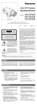
1
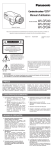
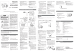
CCTV Cameras (Lens : option) Before attempting to connect or operate this product, please read these instructions completely. FRANÇAIS ENGLISH WV-BP330/WV-BP332/WV-BP334 CAUTION RISK OF ELECTRIC SHOCK DO NOT OPEN CAUTION: TO REDUCE THE RISK OF ELECTRIC SHOCK, DO NOT REMOVE COVER (OR BACK). NO USER SERVICEABLE PARTS INSIDE. REFER SERVICING TO QUALIFIED SERVICE PERSONNEL. SA 1965 The lightning flash with arrowhead symbol, within an equilateral triangle, is intended to alert the user to the presence of uninsulated "dangerous voltage" within the product's enclosure that may be of sufficient magnitude to constitute a risk of electric shock to persons. The exclamation point within an equilateral triangle is intended to alert the user to the presence of important operating and maintenance (servicing) instructions in the literature accompa-nying the appliance. For U.S.A Warning: This equipment generates and uses radio frequency energy and if not installed and used properly, i.e., in strict accordance with the instruction manual, may cause harmful interference to radio communications. It has been tested and found to comply with the limits for a Class A computing device pursuant to Subpart J of Part 15 of FCC Rules, which are designed to provide reasonable protection against such interference when operated in a commercial environment. The serial number of this product may be found on the top of the unit. You should note the serial number of this unit in the space provided and retain this book as a permanent record of your purchase to aid identification in the event of theft. Model No. Serial No. SA 1966 WARNING: TO PREVENT FIRE OR ELECTRIC SHOCK HAZARD, DO NOT EXPOSE THIS APPLIANCE TO RAIN OR MOISTURE. PREFACE ........................................................................................................................................................................ 2 FEATURES ...................................................................................................................................................................... 2 PRECAUTIONS ............................................................................................................................................................... 3 MAJOR OPERATING CONTROLS AND THEIR FUNCTIONS ......................................................................................... 4 CONNECTIONS .............................................................................................................................................................. 8 FOCUS OR FLANGE-BACK ADJUSTMENT .................................................................................................................. 13 INSTALLATION OF CAMERA ........................................................................................................................................ 14 PREVENTION OF BLOOMING AND SMEAR ................................................................................................................ 15 SPECIFICATIONS .......................................................................................................................................................... 16 STANDARD ACCESSORIES ......................................................................................................................................... 17 -1- ENGLISH CONTENTS PREFACE Panasonic’s WV-BP330 series digital cameras introduce a new level of high picture quality and high resolution through the use of a 1/3-inch frame interline transfer CCD image sensor having 768 horizontal pix- els (picture elements), and digital signal processing LSI’s. This model offers cutting-edge technology for advanced video surveillance. FEATURES 1. The following functions are built-in. (1) Auto Light Control (ALC)/Electronic Light Control (ELC) (2) Back Light Compensation (ON: Photometric weight is given to the center of the screen/OFF: Effective if the object is not in the center of the screen) (3) Various External Sync Functions, including Gen-Lock 2. Signal-to-noise ratio of 50 dB 3. Minimum illumination of 0.08 lux (0.008 foot-candle) with F1.4 lenses 4. Horizontal resolution of 570 lines 5. Shooting of shoot indoor scenes with fixed iris lens by use of Electronic Light Control (ELC) function 6. Selectable auto iris control signal for the lens from a video signal or DC control signal -2- PRECAUTIONS 5. Clean the CCD faceplate with care. Do not clean the CCD with strong or abrasive detergents. Use lens tissue or a cotton tipped applicator and ethanol. 1. Do not attempt to disassemble the camera. To prevent electric shock, do not remove screws or covers. There are no user serviceable parts inside. Ask a qualified service person for servicing. 6. Never face the camera towards the sun. Do not aim the camera at bright objects. Whether the camera is in use or not, never aim it at the sun or other extremely bright objects. Otherwise, blooming or smear may be caused. 2. Handle the camera with care. Do not abuse the camera. Avoid striking, shaking, etc. The camera could be damaged by improper handling or storage. 7. Do not operate the camera beyond the specified temperature, humidity or power source ratings. Use the camera under conditions where temperature is between –10°C - +50°C (14°F - 122°F), and humidity is below 90%. The input power source is 120V AC 60Hz for WV-BP330, 12V DC for WVBP332, and 24V AC 60Hz for WV-BP334. 3. Do not expose the camera to rain or moisture, or try to operate it in wet areas. Turn the power off immediately and ask a qualified service person for servicing. Moisture can damage the camera and also create the danger of electric shock. 4. Do not use strong or abrasive detergents when cleaning the camera body. Use a dry cloth to clean the camera when dirty. In case the dirt is hard to remove, use a mild detergent and wipe gently. Caution: To prevent fire or electric shock hazard, a UL listed wire (VW-1, style 1007) should be used for DC 12V or AC 24V Input Terminals. -3- MAJOR OPERATING CONTROLS AND THEIR FUNCTIONS <WV-BP330> LL OFF ELC OFF DC Hi-Z GEN-LOCK INT AGC ON ALC BLC ON VIDEO G/L 75 Ω VIDEO OUT WV- V. PHASE VIDEO LEVEL L H <WV-BP332> DC 12V IN OFF ELC OFF DC Hi-Z GEN-LOCK AGC ON ALC BLC ON VIDEO G/L 75 Ω VIDEO OUT VIDEO LEVEL L H <WV-BP334> AC 24V IN GND 1 2 GEN-LOCK LL OFF ELC OFF DC Hi-Z INT AGC ON ALC BLC ON VIDEO G/L 75 Ω VIDEO OUT V. PHASE VIDEO LEVEL L H -4- BP330 q Auto Iris lens Connector This connector is for connecting the auto iris lens by a 4-pin male connector supplied as a standard accessory (Part No. YFE4191J100). u AC 24V Input Terminal (AC 24V IN (only WV-BP334)) This terminal is for connecting the 24V AC 60Hz power supply cord. i Synchronization Mode Selector (INT, LL (only WV-BP330 and WV-BP334)) Selects the camera synchronization mode from internal sync mode (INT) or line-lock mode (LL). INT: When no signal is supplied to the GEN-LOCK connector, the camera synchronization mode is set to internal 2:1 interlace. Whenever the gen-lock video signal is supplied to the GENLOCK connector, the camera synchronization mode is automatically set to external synchronization. LL: The camera synchronization mode is set to line-lock even if the gen-lock video signal is supplied to the GEN-LOCK connector. Note: Set this selector to INT for gen-lock operation. w Flange-back Adjusting Ring This ring adjusts the back focal length or picture focus. Rotate this ring clockwise for a C-mount lens or counterclockwise for a CS-mount lens. e Lens (option) r Camera Mounting Screw Hole This hole for mounting the camera onto a mounting bracket. t Power Cord (only WV-BP330) Connect this power cord to an electrical outlet of 120V AC 60Hz. y DC 12 V Input Terminal (DC 12V IN (only WV-BP332)) This terminal is for connecting the 12V DC power supply cord. o AGC ON/OFF Selector (AGC ON, OFF) Selects the gain of the video amplifier as follows: AGC ON: When the lens iris is fully open under low light conditions, a clear picture is obtained by automatic increase of the gain. OFF: A natural and low-noise picture is obtained under low light conditions. -5- !0 Automatic Light Control / Electronic Light Control Selector (ALC , ELC) Lets you select the mode according to the lens type that is used with this camera. ALC: Select this mode when an auto iris lens (ALC lens) is used with this camera. ELC: Select this mode when a fixed iris lens or manual iris lens is used with this camera. DC: Select this mode if you are using the auto iris lens that requires a DC drive signal. !3 Gen-lock Termination Selector (Hi-Z, G/L75Ω) Set this selector to Hi-Z when a gen-lock video input signal is looped through. In all other cases, set this selector to 75Ω. !4 Vertical Phase Control (V. PHASE (only WV-BP330 and WV-BP334)) Allows you to adjust the vertical phase of the camera signal to match the vertical phase of the line powers. !1 Back Light Compensation Mode Selector (BLC ON, OFF) Lets you select the mode according to the position of the object and light conditions on the screen. BLC ON: More photometric weight is given to the center of the screen than to the edge of the screen. Select this mode if the background light is strong such as a spotlight. OFF: Select this mode if the main object is not located in the center of the screen and a source of bright light is located near the center of the screen. !5 Video Level Control (VIDEO LEVEL, H(High)L(Low)) Allows you to adjust the video level when the Lens Drive Signal Selector is set to DC and the auto iris lens requiring the DC drive signal is mounted on the camera. Note: The video level should be adjusted by the lens when the auto iris lens requiring the video drive signal is mounted on the camera. !2 Lens Drive Signal Selector (VIDEO, DC) Lets you select the mode according to the type of auto iris lens drive signal to be supplied to the lens from the auto iris lens connector. VIDEO: Select this mode if you are using the auto iris lens that requires a video drive signal. !6 Video Output Connector (VIDEO OUT) This connector is for connecting with the VIDEO IN connector of the monitor. -6- !7 Gen-lock Input Connector (GEN-LOCK) This connector is for connecting an external system for synchronization. Cautions: 1. Connect to 12V DC (10.5V-16V) or 24V AC (19.5V-28V) class 2 power supply only. Make sure to connect the grounding lead to the GND terminal when the power is supplied from a 24V AC power source. 2. To prevent fire or electric shock hazard, use a UL listed wire VW-1, style 1007 cable for the Input Terminal. -7- CONNECTIONS Resistance of copper wire [at 20°C (68°F)] A. WV-BP330 (120V AC 60Hz) Connect the power cord to an electrical outlet of 120V AC 60Hz. B. WV-BP332 (12V DC) Connect the power cord to the DC 12V IN terminal on the rear panel of the WV-BP332. Copper wire size (AWG) #24 (0.22mm2) #22 (0.33mm2) #20 (0.52mm2) #18 (0.83mm2) Resistance Ω/m 0.078 0.050 0.030 0.018 Resistance Ω/ft 0.026 0.017 0.010 0.006 • Calculation of maximum cable length between camera and power supply : 10.5V DC ≤ VA − (R x 0.42 x L) ≤ 16V DC L : Cable length (meters) @ ! R : Resistance of copper wire (Ω/meters) VA : DC output voltage of power supply unit 12 V DC (10.5 V - 16 V) L standard = L minimum = L maximum = -8- VA − 12 0.42 x R VA − 16 0.42 x R VA − 10.5 0.42 x R (meters) (meters) (meters) C. WV-BP334 (24V AC 60Hz) Video Cable Connect the power cable to the AC24V IN terminal on the rear panel of the WV-BP334. 1 1. It is recommended to use a monitor whose resolution is at least equal to that of the camera. 2. Set the termination switch to the 75Ω position on the last monitor. A. Use a 75Ω coaxial cable. B. Set the termination switch to the 75Ω position on the last monitor and to the Hi-Z position on the other monitors. Do not change the positions after setting. 2 24 V AC, 60 Hz (19.5 V - 28 V) Monitor Monitor VIDEO IN Recommended wire gauge sizes for 24V AC line Copper wire size (AWG) Length of Cable (Approx.) #24 (0.22mm2) #22 (0.33mm2) #20 (0.52mm2) #18 (0.83mm2) (m) 95 150 255 425 (ft) 314 495 842 1 403 OUT VIDEO 75 ¶ Hi-Z IN OUT 75 ¶ Hi-Z C. The maximum extensible coaxial cable length between the camera and the monitor is shown below. Caution: To prevent fire or electric shock hazard, a UL listed wire (VW-1, style 1007) should be used for DC 12V or AC 24V Input Terminals. -9- Type of coaxial cable Recommended maximum cable length RG-59/U (3C-2V) RG-6/U (5C-2V) RG-11/U (7C-2V) RG-15/U (10C-2V) (m) 250 500 600 800 (ft) 825 1 650 1 980 2 640 3. Wiring precautions: • Do not bend the coaxial cable into a curve whose radius is smaller than 10 times the cable’s diameter. • Never staple the cable, not even with circular staples. Impedance mismatching will occur. • Never crush or pinch the cable. All of the above will change the impedance of the cable and cause poor picture quality. -10- (2) After connection, assemble the lens connector as follows. Installation of Auto Iris Lens Connector Install the lens connector (YFE4191J100) when using a video drive ALC lens. The installation should be made by qualified service personnel or system installers. (1) Cut the iris control cable at the edge of the lens connector to remove the existing lens connector and then remove the outer cable cover as shown in the diagram below. The pin assignment of the lens connector is as follows: Pin 1: Power source; +9V DC, 50mA max. Pin 2: Not used Pin 3: Video signal; 1.3 V[p-p]/40 kΩ Pin 4: Shield, ground Pin 3 Connector Cover Heat Shrinkable Tubes Automatic Iris Lens Iris Control Cable Connector Note: When the iris control cable is too thick to lock the connector cover with the connector base, cut off the rib on the connector. (Set the Lens Drive Signal Selector to the VIDEO position.) Rib Pin 1 Pin 4 Pin 2 -11- Mounting the Lens Caution for Mounting the Lens Caution: Before you mount the lens, loosen the two screws on the ring, and rotate this ring clockwise until it stops. If the ring is not at the end, the inner lens or CCD image sensor may be damaged. The lens mount should be a C-mount or CS-mount (1”32UN) and the lens weight should be less than 450g (0.99 lbs). If the lens is heavier, both the lens and camera should be secured by using the supporter. The protrusion at the rear of the lens should be as shown below: 1. Mount the lens by turning it clockwise on the lens mount of the camera. 2. Connect the lens cable to the auto iris lens connector on the side of the camera. Screws 1 C-mount: Less than 11.5 mm (7/16”) CS-mount: Less than 7.2 mm (1/4”) 2 Flange-back Adjusting Ring -12- FOCUS OR FLANGE-BACK ADJUSTMENT The following adjustment should be made by qualified service personnel or system installers. 3. Tighten the screws on the flange-back adjusting ring. 1. Loosen the screws on the flange-back adjusting ring. Note: If the camera is connected to the Quad System, glare may appear at the edge of the camera picture on the monitor. If this bothers you, adjust the lens focus to reduce the glare. Focus adjustment for CS-mount lens Focus adjustment for C-mount lens Flange-back Adjusting Ring Screws 2. Turn the flange-back adjusting ring to the desired position. Caution: When the C-mount lens is mounted, do not rotate the ring counterclockwise by force after it stops. If the ring is rotated by force, the inner lens or CCD image sensor may be damaged. -13- INSTALLATION OF CAMERA • Mounting from the bottom • Mounting from the top This camera is designed to be mounted from the bottom, as shown below. The mounting hole is a standard photographic pan-head screw size (1/4” - 20). Remove the mount adapter from the bottom of the camera by removing the two fixing screws. Attach the mount adapter to the top as shown in the diagram, then mount the camera on the mounting bracket. Make sure that the two original fixing screws are used when mounting the mount adapter as longer length screws may damage inner components. <Mounting at top> Fixing Screws Mount Adapter <Mounting at bottom> -14- PREVENTION OF BLOOMING AND SMEAR When the camera is aimed at a bright light, such as a spot light, or a surface that reflects bright light, smear or blooming may appear. Therefore, the camera should be operated carefully in the vicinity of extremely bright objects to avoid smear or blooming. -15- , , , , , , Smear Bright object SPECIFICATIONS Pick-up Device: Scanning Area: Synchronization: Scanning System: Scanning: Horizontal: Vertical: Horizontal Resolution: Video Output: Signal-to-Noise Ratio: Electronic Light Control: Minimum Illumination: Gain Control: Lens Mount: Ambient Operating Temperature: Ambient Operating Humidity: Power Source and Power Consumption: 768 (H) x 494 (V) pixels, Interline Transfer CCD 4.9 (H) x 3.7 (V) mm (Equivalent to scanning area of 1/3” pick-up tube) Internal, External, Line-locked or Multiplexed vertical drive (VD2) selectable 2 : 1 interlace 525 lines / 60 fields / 30 frames 15.734 kHz 59.94 Hz 570 lines 1.0 V[p-p] EIA composite 75 Ω / BNC connector 50 dB (AGC OFF) Equivalent to continuous variable shutter speed between 1/60 s and 1/10 000 s 0.08 lx (0.008 footcandle) at F1.4, AGC ON AGC ON (+18 dB) or OFF selectable C-mount or CS-mount selectable −10°C - +50°C (14°F - 122°F) Less than 90% WV-BP330: 120V AC, 60 Hz, 3.5W WV-BP332: 12V DC, 250 mA WV-BP334: 24V AC, 60 Hz, 3.5W -16- Dimensions (without lens): Weights (without lens): 67 (W) x 55 (H) x 123 (D) mm [2-5/8” (W) x 2-3/16” (H) x 4-13/16” (D)] WV-BP330: 0.62kg (1.40lbs) WV-BP332: 0.445kg (0.98lbs) WV-BP334: 0.470kg (1.04lbs) Weights and dimensions indicated are approximate. Specifications are subject to change without notice. STANDARD ACCESSORIES Body Cap .....................................................................................1 pc. ALC Lens Connector (YFE4191J100) ..........................................1 pc. -17- Video Imaging Systems Company A Division of Panasonic Broadcast & Television Systems Company A Unit of Matsushita Electric Corporation of America Executive Office: One Panasonic Way 4H-2, Secaucus, New Jersey 07094 Regional Offices: Northeast: One Panasonic Way, Secaucus, NJ 07094 (201) 348-7303 Southeast: 1225 Northbrook Parkway, Suite 1-160, Suwanee, GA 30024 (770) 338-6838 Midwest: 1707 North Randall Road, Elgin, IL 60123 (847) 468-5211 Southwest: 8105 Beltsline Road, Suite 100, Irving, TX 75063 (927) 915-1334 Western: 6550 Katella Ave., Cypress, CA 90630 (714) 373-7840 PANASONIC CANADA INC. 5770 Ambler Drive, Mississauga, Ontario, L4W 2T3 Canada (905)624-5010 PANASONIC SALES COMPANY DIVISION OF MATSUSHITA ELECTRIC OF PUERTO RICO, INC. San Gabriel Industrial Park, 65th Infantry Ave. KM. 9.5 Carolina, P.R. 00630 (809)750-4300 N0398-1048 YWV8QA4916BN N 30 Printed in Japan Imprimé au Japon