1
Getting Started
11
- !'%"('"!
- ' & "' - "' &'% , '(%&
- "' ) , '(%&
- &&!! ' "' !#(' ! ('#(' %&&&
- "* ' #'& "' "!'&
- &+ '#& "% ''! # "' - %$(!'+ & (&'"!&
1–2
Getting Started
Getting Started
Introduction
The Purpose of
this Manual
Thank you for purchasing the remote I/O
system for the DL205. This manual shows
you how to install, program, and maintain
the equipment. It also helps you
understand the system operation
characteristics.
This
manual
contains
important
information for personnel who will install
remote I/O, and for the PLC programmer.
If you understand PLC systems our
manuals will provide all the information
you need to get and keep your system up
and running.
Since we constantly try to improve our product line, we occasionally issue addenda
that document new features and changes to the products. If an addendum is
included with this manual, please read it to see which areas of the manual or product
have changed.
Where to Begin
If you already understand the basics of remote I/O systems, you may only want to
skim this chapter, and move on to Chapter 2, “Designing the System”. Be sure to
keep this manual handy for reference when you run into questions. If you are a new
DL205 customer, we suggest you read this manual completely so you can
understand the remote modules, configurations, and procedures used. We believe
you will be pleasantly surprised with how much you can accomplish with
PLCDirect products.
Supplemental
Manuals
Depending on the products you have purchased, there may be other manuals
necessary for you application. You will need to supplement this manual with the
manuals that are written for those products.
Technical Support
We realize that even though we strive to be the best, we may have arranged our
information in such a way you cannot find what you are looking for. First, check these
resources for help in locating the information:
S
Table of Contents – chapter and section listing of contents, in the front
of this manual
S Quick Guide to Contents – chapter summary listing on the next page
S Appendices – reference material for key topics, near the end of this
manual
If you still need assistance, please call us at 800–633–0405. Our technical support
group is glad to work with you in answering your questions. They are available
Monday through Friday from 9:00 A.M. to 6:00 P.M. Eastern Standard Time. If you
have a comment or question about any of our products, services, or manuals, please
fill out and return the ‘Suggestions’ card that was shipped with this manual.
Getting Started
Chapters
1–3
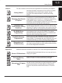
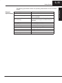
The main contents of this manual are organized into the following six chapters:
Getting Started
Designing Your Remote
I/O System
shows you how to design your system by using worksheets
to keep track of system parameters and the address and
range assignments for remote I/O, needed for programming
and hardware setup. It also gives you guidelines for
calculating a “power budget” to make sure your system does
not draw more than the allowable base current.
3
Installation and
Communication Wiring
Guidelines
shows you how to install your modules. This chapter
includes wiring information, shows you how to set the rotary
dials and DIP switch on each module, how to daisy chain the
remote units, and how to size and use termination resistors.
4
D2–RMSM Setup
Programming
5
DL250/DL350 Setup
Programming
shows you how to use DirectSoft to write the setup program
when using the DL250 or DL350 CPU bottom port as a
remote master. The examples take the information from your
worksheets and help you write a working setup program.
6
Diagnostics and
Troubleshooting
shows you how to interpret the status lights on the modules,
use certain internal relays to monitor communications status,
and monitor diagnostics information.
2
Appendices
shows you how to use DirectSoft to write the remote I/O
setup program when using the D2–RMSM. This chapter
takes the information developed from your worksheets and
helps you write a working setup program.
Additional reference information on remote I/O is in the following three appendices:
A
Remote I/O Worksheets
B
C
Reserved Memory
Tables
Determining I/O Update
Time
included are blank worksheets that you can copy and use to
design your system.
shows the reserved memory locations for the transfer of
remote I/O data. It is cross referenced by data type.
shows you how to calculate the amount of delay inherent
with the transfer of data back and forth between the master
and its remote slaves. Provides tables for all baud rates,
based on the protocol selected and number of I/O points
used.
Getting Started
1
introduces the basic components of the remote I/O system,
an explanation of who needs such a system, and an
overview of the steps necessary to develop a working
system.
1–4
Getting Started
Getting Started
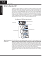
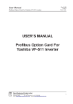
What is Remote I/O?
A remote I/O system allows you to locate I/O modules in bases at some remote
distance from the CPU base, but still under its control. These remote bases have no
CPU of their own, and are completely controlled by the CPU in the main base via a
special module called a remote master. Each remote base unit has a remote slave
that allows the exchange of data with the CPU in the main base via the master
module. The communications link between the master and its slaves is provided by
twisted-pair cable, with baud rates ranging between 19.2 to 614.4 kBaud, depending
on the configuration. Up to 2048 remote I/O points can be supported by the DL250
(896 points for the DL240). The DL230 does not support remote I/O.
One Master in CPU Base (one channel)
Remote Master
Local Base
Remote Slave
Remote Bases
When Do You Need For the DL205 series, the main advantage of remote I/O is that it expands the I/O
capability beyond the local CPU base. Remote I/O can also offer tremendous
Remote I/O?
savings on wiring materials and labor costs for larger systems in which the field
devices are in clusters at various locations. With the CPU in a main control room or
some other central area, only the remote I/O cable is brought back to the CPU base.
This avoids the use of a large number of field wires over greatly separated distances
to all the various field devices. By locating the remote bases and their respective I/O
modules close to the field devices, wiring costs are reduced significantly.
Another inherent advantage of remote I/O is the ability to add or remove slave bases,
or temporarily take a base off line without disrupting the operation of the remaining
system.
Getting Started
With the DL205 system, up to 896 (DL240) or 2048 (DL250) remote I/O points can be
supported, depending on the configuration. This is accomplished with the
D2–RMSM Remote Master module and D2–RSSS Remote Slave modules. The
DL230 does not support remote I/O.
The D2–RMSM remote master supports two different remote I/O communications
protocols:
S The Remote Master protocol (RM–NET) is the same protocol used by the
D4–RM and D4–RS (DL405 Remote Master and Slave) and the built in ports
on the DL250, DL350 and DL450 CPUs. This means that the remote I/O
bases connected to a D2–RMSM in a DL205 CPU base can be a combination
of D2–RSSS and D4–RS (DL405 Remote Slave) modules. Also, the DL405
series CPUs can use DL205 remote bases as remote I/O, for cost and space
savings. RM–NET does not support the use of the built in communications
port on the slave unit.
S The Slice Master protocol (SM–NET) is the same protocol used by the
D4–SM and D4–SS (DL405 Slice Master and Slave) units. This means that
the DL205 series can take advantage of the Slice I/O features by using a
D2–RMSM Master connected to D2–RSSS and/or Slice Slave units, up to the
maximum allowed number of remote units and I/O points, as well as operate
at a higher baud rate. Also, the DL405 Slice Master can use DL205 remote
bases as slaves. This protocol supports the built in RS–232 communications
port on the D2–RSSS.
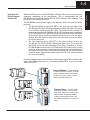
A remote master resides in the CPU base. Depending on the protocol selected, this
master (D2–RMSM) controls up to 7 remote slaves (RM–NET), or up to 31 remote
slaves (SM–NET).
Remote Master – The D2–RMSM
is mounted in the CPU base. Up to two
master modules can be used with the
DL240; up to seven master modules
can be used with the DL250
Remote Slave – The D2–RSSS
modules are placed in remote base
units. Each slave has the I/O circuitry
required to be linked to the master
module via twisted pair cable. One
D2–RSSS is required for each remote
base.
Getting Started
How Does the
DL205 Support
Remote I/O?
1–5
Getting Started
1–6
Getting Started
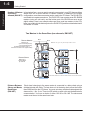
Number of Masters In its simplest form, you may want to use only one master in your CPU base and then
attach from one to seven remote I/O bases. However, in addition to the simple
and Slaves
Allowed (RM–NET) configuration, more than one master can be used in the CPU base. The DL240 CPU
can handle two masters maximum. The DL250 CPU can operate seven D2–RMSM
masters (using a 9–slot rack), and the bottom port of the DL250 can serve as an
eighth master. Here is an example where we have used two masters in the CPU
base (one of which is the bottom port on the DL250 CPU) and then attached a total of
six remote I/O racks.
Two Masters in the Same Base (two channels, RM–NET)
Remote Masters
Maximum of:
2 per CPU base (DL240)
7 per CPU base (DL250)
(for DL250, the bottom port of
the CPU can serve as an eighth master)
CH 1
CH 2
# " " Remote Slaves
Maximum of
7 remote bases
per channel
"
! Distance Between
Each slave belonging to the same master is connected in a daisy chain using a
Slaves and Master, shielded twisted pair cable. The last slave unit in the daisy chain cannot be further
than 3900 feet from the CPU base. You must set rotary switches that designate the
Baud Rates
slaves as No. 1, No. 2, etc. There is a DIP switch on each unit to set the baud rate for
(RM–NET)
communication. You have a choice of either 19.2 kB or 38.4 kB. The slaves and
master must be set to the same baud rate.
1–7
Getting Started
Two Masters in the Same Base (two channels, SM–NET)
CH 1
Remote Masters
Maximum of
seven per CPU base
(with DL250)
CH 2
# " " Remote Slaves
Maximum of
thirty one remote units
per channel
"
! Distance Between Each slave belonging to the same master is hooked together in a daisy chain using a
Slaves and Master, shielded twisted pair cable. At the lowest baud rate, the last slave unit in the daisy
chain cannot be further than 3900 feet from the CPU base. You set rotary switches
Baud Rates
that designate the slaves as No. 1, No. 2, etc. There is a DIP switch on each unit to
(SM–NET)
set the baud rate for communication. You have a choice of 19.2 kB, 38.4 kB,153.6
kB, 307.2kB, or 614.4 kB. The slaves and master must be set to the same baud rate.
Let’s now take a closer look at each of the remote I/O modules.
Getting Started
Number of Masters In the SM–NET mode, one master in your CPU base will allow you to attach from one
to 31 remote I/O units. You may use a maximum of two (with DL240) or seven (with
and Slaves
Allowed (SM–NET) DL250) masters per CPU base, all of which have to be the D2–RMSM module. Here
is an example where we have placed two masters in the CPU base and then
attached a total of eight remote I/O units, which can be a combination of rack and
Slice I/O. Slice I/O units can have unit addresses of 1 to 15 only.
1–8
Getting Started
Getting Started
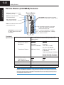
Remote Master (D2-RMSM) Features
RUN--Turns ON when the module
is operating correctly.
Remote Master
DIAG--Turns ON when there
is a hardware failure.
UNIT ADDRS--Rotary switches for setting
the module to be the master – always set to 0
I/O--Turns ON when the
setup program is wrong
LINK--Turns ON when there is a
communications error.
T-–Terminating point that is connected
to point 1 with a jumper at the master
and final slave base units.
1--1st wire of twisted pair (+ Txd/Rxd)
DIP SWITCH--On rear of module
for setting baud rate and other
parameters.
Functional
# of Masters (channels) per CPU
Specifications
Channel Specifications:
Maximum # of Slaves
Baud Rates
Transmission Distance
2--2nd wire of twisted pair (– Txd/Rxd)
3--Shield connection
2 max. for DL240, 7 + 1 max. for DL250 (built–in RM–
NET master feature in DL250 bottom port can be the
eighth master)
RM–NET
7
Selectable
19.2K or 38.4K baud
3900 feet (1.2Km)
SM–NET
31
Selectable
19.2K, 38.4K, 153.6K,
307.2K, or 614.4Kbaud
3900 feet (1.2Km) @ 19.2K
or 38.4Kbaud
1968 feet (600m) @ 153.6Kbaud
984 feet (300m) @ 307.2Kbaud
328 feet (100m) @ 614.4Kbaud
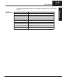
Remote I/O Capacity (see note):
Total Remote I/O
Max. points per channel
DL240
896
512
DL250
2048
512
Module Type
Intelligent
Digital I/O Consumed
None
Communication Method
Asynchronous (half-duplex)
NOTE: Remote I/O Capacity – Total remote I/O available is actually limited by the total
references available.The DL240 CPU supports 320 X inputs and 320 Y outputs, so 640 points is
the limit for I/O references. It is possible to map remote I/O into other types of memory, such as
control relay points, to achieve 896 points. The DL250 has more X, Y, and C points and thus could
use 2048 points, without local I/O.
Getting Started
1–9
Physical
Installation Requirements
Specifications
CPU base only, any slot except adjacent to CPU
Internal Power Consumption
200 mA maximum
Communication Cabling
RS-485 twisted pair, Belden 9841 or equivalent
Operating Temperature
32 to 140° F (0 to 60_ C)
Storage Temperature
–4 to 158° F (–20 to 70_ C)
Relative Humidity
5 to 95% (non-condensing)
Environmental air
No corrosive gases permitted
Vibration
MIL STD 810C 514.2
Shock
MIL STD 810C 516.2
Noise Immunity
NEMA ICS3–304
Getting Started
The following specifications define the operating characteristics of the D2–RMSM
module.
1–10
Getting Started
Getting Started
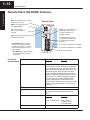
Remote Slave (D2-RSSS) Features
RUN--Turns ON when the module
is operating correctly.
Remote Slave
DIAG--Turns ON when there
is a hardware failure.
I/O--Turns ON when
there is an I/O failure at
the slave
COM –– Communication Port
(in SM–NET mode, can be
used for programmer or
operator interface)
LINK--Turns ON when there is a
communications error.
T-–Terminating point that is
connected to Terminal 1 with
a jumper at the final slave
base unit.
UNIT ADDRS--Rotary switches
on rear of module for setting the
module to be a slave – maximium
base address dependent on protocol selected
1--1st wire of twisted pair (+ Txd/Rxd)
2--2nd wire of twisted pair (–Txd/Rxd)
3--Shield connection
DIP SWITCH--On rear of module
for setting baud rate and other
parameters.
Functional
Slaves per channel
Specifications
RM–NET
7
SM–NET
31
Maximum Slave Points per CPU
No remote I/O for DL230
DL240, DL250, and DL350 support a maximum
of 512 points per channel. The actual I/O available is limited by total available references. The
DL240 has a total of 320 X inputs and 320 Y
outputs available to share between local and
remote I/O, and the DL250 has a total of 512 X
inputs and 512 Y outputs. Mapping remote I/O
into other types of memory could allow 896
points for the DL240, or 2048 points for the
DL250. The DL350 CPU has a maximum configuration of 368 local/expansion I/O and 512 remote I/O.
Module Type
Non–intelligent slave
Digital I/O Consumed
Consumes remote I/O points at a rate equal to
the number of I/O points configured in each
base.
Communication Baud Rates
RM–NET
Selectable
19.2K or 38.4K baud
Communication Failure Response
Selectable to clear or hold last state of outputs
SM–NET
Selectable
19.2K, 38.4K,
153.6K, 307.2K,
or 614.4K baud
Getting Started
1–11
Physical
Installation Requirements
Specifications
CPU slot in any 3, 4, 6, or 9 slot base
Base Power Requirement
200 mA maximum
Communication Cabling
for remote I/O, RS-485 twisted pair, Belden
9841 or equivalent
Communications Port (active in SM–
NET mode only)
RS232C, 9600 Baud, Odd Parity, 8 Data Bits, 1
stop bit (same as top port on DL205 CPUs), K–
sequence
Operating Temperature
32 to 140° F (0 to 60_ C)
Storage Temperature
–4 to 158° F (–20 to 70_ C)
Relative Humidity
5 to 95% (non-condensing)
Environmental air
No corrosive gases permitted
Vibration
MIL STD 810C 514.2
Shock
MIL STD 810C 516.2
Noise Immunity
NEMA ICS3–304
Getting Started
The following specifications define the operating characteristics of the D2–RSSS
module.
1–12
Getting Started
Getting Started
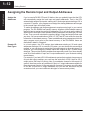
Assigning the Remote Input and Output Addresses
Assign the
Addresses
Remote I/O
Data Types
If you’ve used a DL205 CPU and I/O before, then you probably know that the CPU
will automatically assign the local input and output addresses. That is, the CPU
automatically assigns input points starting at X0, and output points starting at Y0. In
a remote I/O system, your program must assign the starting addresses and ranges
to the remote input and output points.
To make the address and range assignments requires setup logic in your control
program. The D2–RMSM has specific memory locations (called shared memory)
that tell it how to assign the remote I/O addresses. First, you must use the tables in
Appendix B to look up the next available starting address for the data type you want
to use. Then you must calculate the number (range) of input and output points used
per slave. You use a combination of LDA, LD, OUT and WT instructions to store this
information in the shared memory. There are additional setup parameters which the
setup program must write to the shared memory of the D2–RMSM; these are
discussed in detail in Chapter 4.
In a local system, the CPU assigns input addresses starting at X0 and output
addresses starting at Y0. In a remote I/O system, you can choose this conventional
method, or you can choose to assign the inputs and outputs to other data types. For
example, you could assign the remote inputs and outputs as the C (control relay)
data type. This provides flexibility and becomes especially useful if you have already
used all of the available X input and Y output addresses in your local and existing
remote bases.
For example, if you had a D2–240 local/remote system that required a large amount
of input and output modules, you could use the entire limit of 320 X input or 320 Y
output points (640 total I/O points). Now if you added a channel in the remote I/O
system, there may not be any additional X input or Y output addresses available for
these inputs and outputs. (In the vast majority of remote I/O systems, you will be able
to use the X input and Y output addresses, but you can see that there may be
occasions when you need a different data type for some remote points.)
Getting Started
1–13
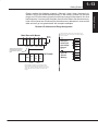
Remote I/O Address and Range Assignment
Main Base with Master
CPU 16
16
16
16
I
I
I
O
Master
Module
!!( $ % $%! ! % $%&" !
( $%$ &" % %!% "&% !&%"&% # $
!# % Set up Remote Input
and Output
Ranges
X0-X17 X20-X37 X40-X57 Y0-Y17
V40400 V40401 V40402 V40500
These points are automatically assigned to memory
by the CPU for the local
base.
1st Remote
Slave
Module
16
8
8
I
O
O
X60-X77 Y20-Y27 Y30-Y37
V40403
V40501
)% ' $%#% "&% #$$ $ )% ' $%#% !&%"&% #$$ $ # # "&%$ !&%"&%$ % #!%
$ ## %! % &# ! "! %$ $ %
range
Store to
Shared
Memory
Getting Started
Please consider the following example. Although it hasn’t been discussed yet,
address 124 (in the RMSM shared memory) is the memory location for the input
range, and 126 is the memory location for the output range for the channel.You must
load temporary V memory with the totals, then store the data to the shared memory.
Later in this manual we will show all the shared memory addresses in a convenient
table and we’ll go into greater detail with complete examples.
1–14
Getting Started
Getting Started
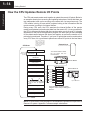
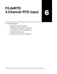
How the CPU Updates Remote I/O Points
The CPU and remote master work together to update the remote I/O points. Below is
an example showing how scanning and updating takes place. Notice that there are
two independent scan cycles occuring at the same time, but asynchronously. The
CPU module is doing its scan which includes looking at the information that the
remote master is writing to its internal buffers.
During every CPU scan, the CPU examines the internal buffers of the remote
master, and updates input and output data from the remote I/O. It is very possible for
the CPU to be scanning faster than the remote master can do its scan. It is largely
dependent on the size of the application program, the baud rate you have selected
for the data transfer between the slaves and master, as well as the number of I/O
points being monitored. Therefore, if you have I/O points that must be monitored on
every CPU scan, it’s a good idea to place these critical I/O points in the local base.
The CPU reads the
status of any input
points associated with
remote I/O and stores
the status in the input
image register.
CPU Scan
Remote Scan
!$ #! " !
Read Inputs
Mapped into
memory using
your RLL.
The Remote Master obtains
the I/O status from the
Remote Slaves.
O000=40600 octal
O004=0008 bcd
Read Inputs from
Remote I/O
...
...
C2
C1
C0
ON OFF OFF
#" !"
" " !!
Service Peripherals
CPU Bus Communication
Update clock, Special Relays
Solve the Application Program
C0
Y1
The status of the input image register
is used to solve the application
program.
Write Outputs
Write Outputs to Remote I/O
Remote Master
Remote Master Buffer
Remote Slave #1
#" #
In this example, we have 8 inputs
using the control relay C data type in
Slave #1.
Diagnostics
NOTE: In some cases it may be helpful to understand the update time required for a
Remote I/O system. Appendix C shows example calculations.
Getting Started
1–15
3 Easy Steps for Setting Up Remote I/O
Main Base with Master
16 16 16 16
I I I O
16 8
8
I O O
Slave 1
16 16 16
I
I O
Slave 2
2
Install the
Components
3
Write the Setup
Program
Install the bases and insert the master(s)
and the remote slaves. Wire all of your I/O
to match your information in Step 1. Set
the hardware switches so that the CPU
can identify the master and slave units.
This also will set the baud rate for data
transfer, protocol selection, and other
parameters. Installation is covered in
Chapter 3.
Write the RLL setup program. Complete
examples are covered in Chapter 4.
The next two pages provide a complete
overview of the entire process for an
example remote I/O system. Of course, to
learn all of the details, you should read
each chapter carefully.
Set up Input
and Output
Ranges
Store to
Shared
Memory
Getting Started
Figure out how much remote I/O you will need. This will, in turn, tell you which CPU
and the number of remote masters and slaves you will need. In Chapter 2, we will
Design the Remote show you how to use worksheets to plan and keep track of your data type
assignments. We’ll also show you how to determine the correct addresses for
I/O System
reading and writing remote I/O data, as well as how to choose other remote I/O
system parameters.
1
Getting Started
1–16
Getting Started
Step 1: Design
EXAMPLE:
307.2 kBaud, D2-240, SM–NET
Master Module
the Remote I/O System
Main Base with Master
CPU
Remote Slave Worksheet
16
16
16
16
I
I
I
O
Remote Base Address_________(Choose
1–7 for RM–NET or 1–31 for SM–NET)
Module
Name
Input Address
0
X060
1
2
X0-X17 X20-X37 X40-X57 Y0-Y17
V40400 V40401 V40402 V40500
1st Remote
Slave
16
8
8
I
O
O
I
8
16
I
O
Output Address
No. of Outputs
Y020
8
Y030
8
16
4
5
6
7
2nd Remote
8
OUTPUT
No. of Inputs
3
X60-X77 Y20-Y27 Y30-Y37
V40403
V40501
Slave
INPUT
Slot
Number
X060
Input Bit Start Address:________V-Memory
Address*:V_______
40403
16
Total Input Points_____
Y020
40501
Output Bit Start Address:________V-Memory
Address*:V______
16
Total Output Points_____
X100-X107 X110-X117 Y40-Y57
V40502
V40404
* The D2–RMSM automatically assigns I/O addresses in sequence based on
Slave # 1’s starting addresses. The DL250/DL350 CPU port setup program
requires these addresses for each slave.
3rd Remote
Remote Slave Worksheet
Slave
16
8
8
I
O
O
2
Remote Base Address_________(Choose
1–7 for RM–net or 1–31 for SM–NET)
Slot
Number
X120-X137 Y60-Y67 Y70-Y77
V40405
V40503
Module
Name
INPUT
Input Address
OUTPUT
No. of Inputs
0
08ND3
X100
8
1
08ND3
X110
8
2
16TD1–2
Output Address
Y040
No. of Outputs
16
3
Remote Slave Worksheet
4
3
Remote Base Address_________(Choose
1–7 for RM–NET or 1–31 for SM–NET)
Slot
Number
Module
Name
INPUT
Input Address
6
OUTPUT
No. of Inputs
Output Address
No. of Outputs
0
1
Y060
8
2
Y070
8
3
X120
5
16
7
40404
X100
Input Bit Start Address:________V-Memory
Address*:V_______
16
Total Input Points_____
40502
Y040
Output Bit Start Address:________V-Memory
Address*:V_______
16
Total Output Points_____
4
* The D2–RMSM automatically assigns I/O addresses in sequence based on
Slave # 1’s starting addresses. The DL250/DL350 CPU port setup program
requires these addresses for each slave.
5
6
7
Note:
40405
X120
Input Bit Start Address:________V-Memory
Address*:V_______
16
Total Input Points_____
40503
Y060
Output Bit Start Address:________V-Memory
Address*:V_______
16
Total Output Points_____
* The D2–RMSM automatically assigns I/O addresses in sequence based on
Slave # 1’s starting addresses. The DL250/DL350 CPU port setup program
requires these addresses for each slave.
The Remote Slave Worksheet is located
in Appendix A.
Getting Started
1–17
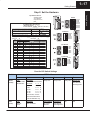
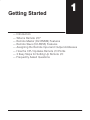
Step 2: Set the Hardware
Master
1=OFF
2=ON
3=ON
4=OFF
5=OFF
6=OFF
7=OFF
8=OFF
Channel Configuration Worksheet
D2–RMSM Remote Master Module
4 (1–7)_
Master Slot Address _____
Protocol Selected _________
SM–NET (RM–NET or SM–NET)
RM–NET
Configuration Parameter
SM–NET
! 19.2
38.4
N/A
YES
NO
19.2
38.4
307.2 614.4
YES
NO
YES
NO
1st Remote
153.6
1=OFF
2=ON
3=ON
4=OFF
5=OFF
6=OFF
O
F
F
40403 Starting Output V Memory Address: V _____
40501
Starting Input V Memory Address: V______
48
Total Inputs ________
Slave
Station
No. of Inputs No. of Outputs
N/A
0
1
2
3
4
5
6
7
8
9
10
11
12
13
14
15
48
Total Outputs ________
16
16
N/A
16
16
16
16
Slave
Station
No. of Inputs No. of Outputs
16
17
18
19
20
21
22
23
24
25
26
27
28
29
30
31
2nd Remote
1=OFF
2=ON
3=ON
4=OFF
5=OFF
6=OFF
O
F
F
3rd Remote
1=OFF
2=ON
3=ON
4=OFF
5=OFF
6=OFF
O
F
F
Chart for DIP Switch Settings
DIP Position
Module
1
Master
(RMSM)
Slave
(RSSS)
2,3,4
6
7
Mode
Baud Rate
Always OFF
OFF=SM–NET
Switch Position
ON=RM–NET Baud Rate
2 3 4
19.2K
O O O
38.4K
X O O
153.6K
O X O
307.2K
X X O
614.4K
O O X
where X=ON, O=OFF
Note: Baud rates above
38.4K for SM–NET only
Always OFF
Always OFF Diagnostics
Mode
Same as
Master
Diagnostics
OFF=Normal
ON=Diagnostic
Baud Rate
Same as Master
5
Output Default
OFF=Clear
ON=Hold
8
OFF=Normal
ON=Diagnostic
N/A
N/A
Getting Started
Dip Switches Set for:
SM–NET mode
307.2 KBaud
Outputs clear on
fault
1–18
Getting Started
Getting Started
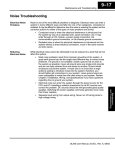
Step 3: Write the Setup Program
RLL Program
Go to remote
I/O subroutine
Main Program Body
from bottom of previous column
Remote I/O Subroutine
Initiate Setup
Bits 0,1,2=7 initiates setup
Store in temporary memory
Rack/Slot Address of Master
Number of bytes to write
Number of bytes to write
to top of next column
Store in temporary memory
Rack/Slot Address of Master
Number of bytes to write
Address From Table Below
Store to
Shared
Memory
Store in temporary memory
number of output points
Set up Complete Code
Store in temporary memory
number of input points
Store in temporary memory
number of output points
Write slave range data
C1 means store settings
Store in temporary memory
Rack/Slot Address of Master
Number of bytes to write
Address From Table Below
Write Setup Complete Byte
Quick Reference Table
of Shared Memory Addresses
Store in temporary memory
D2–RMSM
Setup Initiation Byte
176
Setup Complete Byte
177
Store in temporary memory
Output Number of Number of
Slave Input
Address Address Input Pts Output Pts
ALL
000
002
124
126
1
N/A
N/A
004
006
Write input and output pointers
2
N/A
N/A
010
012
number of input points
3
N/A
N/A
014
016
4
N/A
N/A
020
022
5
N/A
N/A
024
026
6
N/A
N/A
030
032
7
N/A
N/A
034
036
Store in temporary memory
number of output points
Starting input address (X060)
Address From Table Below
Write total range data
Number of bytes to write
Set up 1st
Remote Input
and Output
Ranges
Address From Table Below
Rack/Slot Address of Master
Store to
Shared
Memory
Store to
Shared
Memory
Set up 3rd
Remote Input
and Output
Ranges
Starting output address (Y020)
Store in temporary memory
Rack/Slot Address of Master
Set up Input
and Output
Pointers
Store in temporary memory
total number of output points
Set up 2nd
Remote Input
and Output
Ranges
total number of input points
Store to
Shared
Memory
Address From Table below
Write Address Config. data
Set up Channel
Input and Output Ranges
number of input points
Store to
Shared
Memory
first scan relay
Store in temporary memory
Getting Started
1–19
Frequently Asked Questions
Q. What if I want to add remote I/O after I have programmed the system?
A. Your setup program can allot unused slots to I/O in a remote slave base, or a block
of I/O at the end of a channel, which you can install at a later date. If the local base
has blank slots, you can install a D2–RMSM to add a new channel.
Q. Can I use this remote I/O with other DL series products?
A. Yes, the D2–RSSS slave units can be attached to the DL350 and DL450 CPU
bottom ports, as well as the D4–RM Remote Master or D4–SM Slice Master. The
D2–RMSM remote master can communicate to D4–RS remote slaves or D4–SS
slice slaves. This manual covers DL350 setup programming in Chapter 5; refer to
the DL405 User Manual, D4–RM Remote Master manual, or DL405 Slice I/O
manual to configure and program a DL405 system that includes D2–RSSS slave
units.
Q. Can I use a programmer or operator interface on the remote I/O link?
A. Yes, in the SM–NET protocol mode, the communications port on the D2–RSSS
remote slave supports a handheld programmer, DirectSoft, or an operator interface
such as the DV–1000. Note that since the bottom port of the DL250 or DL350 CPU
supports the RM–NET mode only, you cannot use the remote communications port
on slaves which are attached to the CPU.
Q. What if my cable routing causes the channel communication cable to exceed the
maximum allowed distance?
A. You may need to reconsider the physical layout of your system. For example, you
could split one large channel into two channels whose individual cable lengths would
be acceptable. Or you could locate the local rack that contains the master modules in
the “center” of the system, and radiate multiple channel communications cables in
many directions.
Getting Started
Q. How much remote I/O can I have?
A. The physical limitation depends on the CPU and the protocol you select (i.e.
number of channels and number of slaves per channel). In terms of addressing the
remote I/O, you can use up to the maximum input and output addresses allowed for
the CPU chosen (640 for the DL240, 1024 for the DL250) if you have no local I/O. If
you need more, you can define inputs and/or outputs to use the C (control relay)
memory type, up to the maximum address available. In theory, this could give you
896 I/O for the DL240, and 2048 I/O for the D250. For the DL350 CPU, the bottom
port can have the maximum of 512 remote points. Combined with the maximum
local/expansion configuration of 368 points, this could give you 880 total I/O for a
DL350 system.