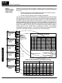
1
D4--RM, D4--RS & D4--RSDC
Remote Master/Remote Slave
Manual Number D4--REMIO--M
Shaded area represents the die-cut covers from
Imaging Technologies, 5-98
WARNING
Thank you for purchasing automation equipment from PLCDirectä. We want your new DirectLOGICä automation
equipment to operate safely. Anyone who installs or uses this equipment should read this publication (and any other
relevant publications) before installing or operating the equipment.
To minimize the risk of potential safety problems, you should follow all applicable local and national codes that regulate
the installation and operation of your equipment. These codes vary from area to area and usually change with time. It is
your responsibility to determine which codes should be followed, and to verify that the equipment, installation, and
operation is in compliance with the latest revision of these codes.
At a minimum, you should follow all applicable sections of the National Fire Code, National Electrical Code, and the
codes of the National Electrical Manufacturer’s Association (NEMA). There may be local regulatory or government
offices that can also help determine which codes and standards are necessary for safe installation and operation.
Equipment damage or serious injury to personnel can result from the failure to follow all applicable codes and
standards. We do not guarantee the products described in this publication are suitable for your particular application,
nor do we assume any responsibility for your product design, installation, or operation.
If you have any questions concerning the installation or operation of this equipment, or if you need additional
information, please call us at 1--800--633--0405.
This publication is based on information that was available at the time it was printed. At PLCDirectä we constantly
strive to improve our products and services, so we reserve the right to make changes to the products and/or
publications at any time without notice and without any obligation. This publication may also discuss features that may
not be available in certain revisions of the product.
Trademarks
This publication may contain references to products produced and/or offered by other companies. The product and
company names may be trademarked and are the sole property of their respective owners. PLCDirectä disclaims any
proprietary interest in the marks and names of others.
Stage is a trademark of Koyo Electronics Industries Co., LTD. Think & Do Software is a trademark of Think & Do
Software, Inc. Texas Instruments is a registered trademark of Texas Instruments, Inc. TI, TIWAY, Series 305, Series
405, TI305, and TI405 are trademarks of Texas Instruments, Inc. Siemens and SIMATIC are registered trademarks of
Siemens, AG. GE is a registered trademark of General Electric Corporation. Series One is a registered trademark of
GE Fanuc Automation North America, Inc. MODBUS is a registered trademark of Gould, Inc. IBM is a registered
trademark of International Business Machines. MS-DOS and Microsoft are registered trademarks of Microsoft
Corporation. Windows and Windows NT are trademarks of Microsoft Corporation. OPTOMUX and PAMUX are
trademarks of OPTO 22.
Copyright 1997, PLCDirectä Incorporated
All Rights Reserved
No part of this manual shall be copied, reproduced, or transmitted in any way without the prior, written consent of
PLCDirectä Incorporated. PLCDirectä retains the exclusive rights to all information included in this document.
1
Manual Revisions
If you contact us in reference to this manual, be sure and include the revision number.
Title: DL405 Remote Master/Remote Slave D4--RM, D4--RS, and D4--RSDC, Rev C
Manual Number: D4--REMIO--M
Issue
Original
Date
11/94
Effective Pages
Cover/Copyright
Contents
1-1 -- 1-13
2--1 -- 2-9
3-1 -- 3-9
4-1 -- 4-11
A-1 -- A-2
B-1 -- B-4
C-1 -- C--6
Description of Changes
Original Issue
Rev. A
1/95
Adds FILL instruction in several RLL
examples.
Rev. B
4/95
Corrects LDA instruction in several RLL
examples.
Rev. C
6/98
Minor corrections
1
Table of Contents
i
Chapter 1: Getting Started
Introduction . . . . . . . . . . . . . . . . . . . . . . . . . . . . . . . . . . . . . . . . . . . . . . . . . . . . . . . . . . . . . . . . . . . . . . . . .
The Purpose of this Manual . . . . . . . . . . . . . . . . . . . . . . . . . . . . . . . . . . . . . . . . . . . . . . . . . . . . . . . . .
Who Should Read this Manual . . . . . . . . . . . . . . . . . . . . . . . . . . . . . . . . . . . . . . . . . . . . . . . . . . . . . .
Where to Begin . . . . . . . . . . . . . . . . . . . . . . . . . . . . . . . . . . . . . . . . . . . . . . . . . . . . . . . . . . . . . . . . . . .
Supplemental Manuals . . . . . . . . . . . . . . . . . . . . . . . . . . . . . . . . . . . . . . . . . . . . . . . . . . . . . . . . . . . . .
How this Manual is Organized . . . . . . . . . . . . . . . . . . . . . . . . . . . . . . . . . . . . . . . . . . . . . . . . . . . . . .
Technical Assistance . . . . . . . . . . . . . . . . . . . . . . . . . . . . . . . . . . . . . . . . . . . . . . . . . . . . . . . . . . . . . .
What is Remote I/O? . . . . . . . . . . . . . . . . . . . . . . . . . . . . . . . . . . . . . . . . . . . . . . . . . . . . . . . . . . . . . . . . .
When Do You Need Remote I/O? . . . . . . . . . . . . . . . . . . . . . . . . . . . . . . . . . . . . . . . . . . . . . . . . . . .
Number of Masters and Slaves Allowed . . . . . . . . . . . . . . . . . . . . . . . . . . . . . . . . . . . . . . . . . . . . . .
How Does the DL405 Support Remote I/O? . . . . . . . . . . . . . . . . . . . . . . . . . . . . . . . . . . . . . . . . . .
Distance Between Slaves and Master, Baud Rates . . . . . . . . . . . . . . . . . . . . . . . . . . . . . . . . . . . .
Remote Master (D4-RM) Features . . . . . . . . . . . . . . . . . . . . . . . . . . . . . . . . . . . . . . . . . . . . . . . . . . . . .
Specifications . . . . . . . . . . . . . . . . . . . . . . . . . . . . . . . . . . . . . . . . . . . . . . . . . . . . . . . . . . . . . . . . . . . . .
Remote Slave (D4-RS or D4-RSDC) Features . . . . . . . . . . . . . . . . . . . . . . . . . . . . . . . . . . . . . . . . . .
Specifications . . . . . . . . . . . . . . . . . . . . . . . . . . . . . . . . . . . . . . . . . . . . . . . . . . . . . . . . . . . . . . . . . . . . .
Assigning the Remote Input and Output Addresses . . . . . . . . . . . . . . . . . . . . . . . . . . . . . . . . . . . .
You Assign the Addresses . . . . . . . . . . . . . . . . . . . . . . . . . . . . . . . . . . . . . . . . . . . . . . . . . . . . . . . . . .
Remote I/O Data Types . . . . . . . . . . . . . . . . . . . . . . . . . . . . . . . . . . . . . . . . . . . . . . . . . . . . . . . . . . . .
Specify Addresses with Setup Logic . . . . . . . . . . . . . . . . . . . . . . . . . . . . . . . . . . . . . . . . . . . . . . . . .
How the CPU Updates Remote I/O Points . . . . . . . . . . . . . . . . . . . . . . . . . . . . . . . . . . . . . . . . . . . . .
1--2
1--2
1--2
1--2
1--2
1--3
1--3
1--4
1--4
1--5
1--5
1--6
1--7
1--7
1--8
1--8
1--9
1--9
1--9
1--9
1--10
3 Easy Steps for Setting Up Remote I/O . . . . . . . . . . . . . . . . . . . . . . . . . . . . . . . . . . . . . . . . . . . . . . .
Step One: Design the System . . . . . . . . . . . . . . . . . . . . . . . . . . . . . . . . . . . . . . . . . . . . . . . . . . . . . . .
Step Two: Install the Components . . . . . . . . . . . . . . . . . . . . . . . . . . . . . . . . . . . . . . . . . . . . . . . . . . .
Step Three: Write the Setup Program . . . . . . . . . . . . . . . . . . . . . . . . . . . . . . . . . . . . . . . . . . . . . . . .
Example Setup Diagram . . . . . . . . . . . . . . . . . . . . . . . . . . . . . . . . . . . . . . . . . . . . . . . . . . . . . . . . . . . . .
1--11
1--11
1--11
1--11
1--12
Chapter 2: Designing a Remote I/O System
Designing Your System . . . . . . . . . . . . . . . . . . . . . . . . . . . . . . . . . . . . . . . . . . . . . . . . . . . . . . . . . . . . . .
Determine I/O Needed and How Many Masters & Slaves . . . . . . . . . . . . . . . . . . . . . . . . . . . . . . .
Define Your Idea By Using Worksheets . . . . . . . . . . . . . . . . . . . . . . . . . . . . . . . . . . . . . . . . . . . . . .
Filling Out the Remote Slave Worksheet for Slave #1 . . . . . . . . . . . . . . . . . . . . . . . . . . . . . . . . . .
Filling Out the Remote Slave Worksheet for Slave #2 . . . . . . . . . . . . . . . . . . . . . . . . . . . . . . . . . .
Filling Out the Remote Slave Worksheet for Slave #3 . . . . . . . . . . . . . . . . . . . . . . . . . . . . . . . . . .
Calculating the Power Budget . . . . . . . . . . . . . . . . . . . . . . . . . . . . . . . . . . . . . . . . . . . . . . . . . . . . . . . .
Managing your Power Resource . . . . . . . . . . . . . . . . . . . . . . . . . . . . . . . . . . . . . . . . . . . . . . . . . . . .
CPU Power Specifications . . . . . . . . . . . . . . . . . . . . . . . . . . . . . . . . . . . . . . . . . . . . . . . . . . . . . . . . . .
Module Power Requirements . . . . . . . . . . . . . . . . . . . . . . . . . . . . . . . . . . . . . . . . . . . . . . . . . . . . . . .
Power Budget Calculation Example . . . . . . . . . . . . . . . . . . . . . . . . . . . . . . . . . . . . . . . . . . . . . . . . . .
Which Modules Can Go In the Remote Bases . . . . . . . . . . . . . . . . . . . . . . . . . . . . . . . . . . . . . . . . . .
2--2
2--2
2--2
2--3
2--4
2--5
2--6
2--6
2--6
2--6
2--8
2--9
ii
Table of Contents
Chapter 3: Installation & Field Wiring Guidelines
Introduction . . . . . . . . . . . . . . . . . . . . . . . . . . . . . . . . . . . . . . . . . . . . . . . . . . . . . . . . . . . . . . . . . . . . . . . . .
4 Easy Steps: . . . . . . . . . . . . . . . . . . . . . . . . . . . . . . . . . . . . . . . . . . . . . . . . . . . . . . . . . . . . . . . . . . . . .
3--2
3--2
Step One: Setting the Front Rotary Switch . . . . . . . . . . . . . . . . . . . . . . . . . . . . . . . . . . . . . . . . . . . .
3--3
Step Two: Setting the Rear DIP Switches . . . . . . . . . . . . . . . . . . . . . . . . . . . . . . . . . . . . . . . . . . . . . .
3--4
Step Three: Inserting the Module in the Base . . . . . . . . . . . . . . . . . . . . . . . . . . . . . . . . . . . . . . . . . .
3--6
Step Four: Connecting the Wiring . . . . . . . . . . . . . . . . . . . . . . . . . . . . . . . . . . . . . . . . . . . . . . . . . . . .
General Wiring Guidelines . . . . . . . . . . . . . . . . . . . . . . . . . . . . . . . . . . . . . . . . . . . . . . . . . . . . . . . . . .
Power Connections for the D4-RS or D4-RSDC . . . . . . . . . . . . . . . . . . . . . . . . . . . . . . . . . . . . . . .
Cabling Between the Master and Slaves . . . . . . . . . . . . . . . . . . . . . . . . . . . . . . . . . . . . . . . . . . . . .
Termination Resistors . . . . . . . . . . . . . . . . . . . . . . . . . . . . . . . . . . . . . . . . . . . . . . . . . . . . . . . . . . . . . .
Connecting the Run Output Circuit . . . . . . . . . . . . . . . . . . . . . . . . . . . . . . . . . . . . . . . . . . . . . . . . . . .
3--7
3--7
3--7
3--8
3--8
3--9
Chapter 4: Writing the Setup Program
Getting Started with Your Programming . . . . . . . . . . . . . . . . . . . . . . . . . . . . . . . . . . . . . . . . . . . . . . .
4--2
Writing Your Remote I/O Setup . . . . . . . . . . . . . . . . . . . . . . . . . . . . . . . . . . . . . . . . . . . . . . . . . . . . . . .
Step 1: Decide How You Are Going to Call Your Program . . . . . . . . . . . . . . . . . . . . . . . . . . . . . . .
Step 2: Write the Setup Logic For Each Remote Base . . . . . . . . . . . . . . . . . . . . . . . . . . . . . . . . . .
Tell the CPU That You Are Finished With the Setup . . . . . . . . . . . . . . . . . . . . . . . . . . . . . . . . . . . .
A Completed Example . . . . . . . . . . . . . . . . . . . . . . . . . . . . . . . . . . . . . . . . . . . . . . . . . . . . . . . . . . . . .
4--3
4--3
4--4
4--5
4--6
Special Relays Used for Remote I/O . . . . . . . . . . . . . . . . . . . . . . . . . . . . . . . . . . . . . . . . . . . . . . . . . .
4--8
How to Use the Special Relays . . . . . . . . . . . . . . . . . . . . . . . . . . . . . . . . . . . . . . . . . . . . . . . . . . . . . . .
C670/C674: Setup Complete (Mandatory) . . . . . . . . . . . . . . . . . . . . . . . . . . . . . . . . . . . . . . . . . . . .
C700 to C707 andC720 to C727: Locate Communications Error (Optional) . . . . . . . . . . . . . . .
C671/C675: I/O Status On Error (Optional) . . . . . . . . . . . . . . . . . . . . . . . . . . . . . . . . . . . . . . . . . . .
C673/C677: Error/Restart But Ignore Problem Area (Optional) . . . . . . . . . . . . . . . . . . . . . . . . . .
C710 to C717 andC730 to C737: Communications OK Status (Optional) . . . . . . . . . . . . . . . . .
Example of RLL Using All the Special Relays . . . . . . . . . . . . . . . . . . . . . . . . . . . . . . . . . . . . . . . . .
4--9
4--9
4--9
4--9
4--10
4--10
4--11
Appendix A : Remote I/O Worksheet
Appendix B: Reserved Memory Tables
Remote Input/Output (GX) Addresses . . . . . . . . . . . . . . . . . . . . . . . . . . . . . . . . . . . . . . . . . . . . . . . . .
B--2
Standard Input (X) Addresses . . . . . . . . . . . . . . . . . . . . . . . . . . . . . . . . . . . . . . . . . . . . . . . . . . . . . . . .
B--3
Standard Output (Y) Addresses . . . . . . . . . . . . . . . . . . . . . . . . . . . . . . . . . . . . . . . . . . . . . . . . . . . . . .
B--4
Control Relay (C) Addresses . . . . . . . . . . . . . . . . . . . . . . . . . . . . . . . . . . . . . . . . . . . . . . . . . . . . . . . . .
B--5
Appendix C: Determining I/O Update Time
Overview . . . . . . . . . . . . . . . . . . . . . . . . . . . . . . . . . . . . . . . . . . . . . . . . . . . . . . . . . . . . . . . . . . . . . . . . . . .
C--2
Remote I/O Update Table . . . . . . . . . . . . . . . . . . . . . . . . . . . . . . . . . . . . . . . . . . . . . . . . . . . . . . . . . . . . .
C--3
Calculating Total Delay for the System . . . . . . . . . . . . . . . . . . . . . . . . . . . . . . . . . . . . . . . . . . . . . . . .
Total Delay Time Formulas . . . . . . . . . . . . . . . . . . . . . . . . . . . . . . . . . . . . . . . . . . . . . . . . . . . . . . . . .
Delay Time Example . . . . . . . . . . . . . . . . . . . . . . . . . . . . . . . . . . . . . . . . . . . . . . . . . . . . . . . . . . . . . . .
C--4
C--5
C--6
Getting Started
11
In This Chapter. . . .
— Introduction
— What is Remote I/O
— Remote Master (D4-RM) Features
— Remote Slave (D4-RS or D4-RSDC) Features
— Assigning the Remote Input and Output Addresses
— How the CPU Updates Remote I/O Points
— 3 Easy Steps for Setting Up Remote I/O
1--2
Getting Started
Remote I/O
Getting Started
Manual Introduction
The Purpose of
this Manual
This manual shows you how to install, program, and maintain the equipment. It also
helps you understand the system operation characteristics.
Who Should Read
this Manual
If you understand PLC systems, our manuals will provide all the information you
need to get and keep your remote I/O system up and running. We will use examples
and explanations to clarify our meaning and perhaps help you brush up on specific
features used in the DL405 system. This manual is not intended to be a generic PLC
training manual, but rather a user reference manual for the DL405 remote I/O
system.
Supplemental
Manuals
Depending on the products you have purchased, there may be other manuals
necessary for your application. You will want to supplement this manual with any
other manuals written for other products. We suggest:
S
S
Technical Support
D4-USER-M (the D4-405 User Manual)
DA-DSOFT-M ( the DirectSOFT User Manual)
We realize that even though we strive to be the best, the information may be
arranged in such a way you cannot find what you are looking for. First, check these
resources for help in locating the information:
S
S
S
S
Table of Contents -- chapter and section listing of contents, in the front
of this manual
Quick Guide to Contents -- chapter summary listing on the next page
Appendix -- reference material for commonly used networking terms
Index -- alphabetical listing of key words, at the end of this manual
You can also check our online resources for the latest product support information:
S Internet -- the address of our Web site is http://www.plcdirect.com
S Bulletin Board Service(BBS) -- call (770)--844--4209
If you still need assistance, please call us at 800--633--0405. Our technical support
group is glad to work with you in answering your questions. They are available
Monday through Friday from 9:00 A.M. to 6:00 P.M. Eastern Standard Time. If you
have a comment or question about any of our products, services, or manuals, please
fill out and return the ‘Suggestions’ card that was shipped with this manual.
Getting Started
1--3
The beginning of each chapter will list the
key topics that can be found in that
chapter.
Chapters
Below is a table showing a summary of contents provided within each section of this
manual. The manual is organized into the following four chapters:
1
2
1
contains information you need to know to get started. It
includes a brief description of a remote I/O system, the basic
Getting Started
components of the system, and an overview of the steps
necessary to develop a working system.
shows you how to design your system. It includes a tutorial
on
how to use worksheets to keep track of all the remote I/O
Designing Your Remote
and the address assignments for remote I/O. It provides the
I/O System
framework for developing the necessary information you will
need for programming and hardware setup.
3
Installation and
Communication Wiring
Guidelines
shows you how to install your modules. This chapter
includes wiring information, shows you how to set the rotary
dial and dip switch on each module, how to daisy chain the
remote units, how to size and use termination resistors, and
how to connect the Run Output circuit.
4
Writing the Setup
Program
shows you how to use DirectSOFT to write the remote I/O
setup program. This chapter takes the information developed
from your worksheets and helps you develop a working
program.
Appendices
A
Additional information is available in the following appendices.
Remote I/O Worksheet
B
Reserved Memory
Tables
C
Determining I/O
Update Time
included is a blank worksheet that can be copied and used
for designing your system.
shows the reserved memory locations for the transfer of
remote I/O data. It is cross-referenced by data type.
shows you how to calculate the amount of delay inherent
with the transfer of data back and forth between the master
and its remote slaves. Provides tables for both 19.2 kB and
38.4 kB, based on number of I/O points used.
Remote I/O
Getting Started
Key Topics for
Each Chapter
1--4
Getting Started
Remote I/O
Getting Started
What is Remote I/O?
A remote I/O system allows you to locate I/O modules in bases at some remote
distance from the CPU base, but still under its control. These remote bases have no
CPU of their own, and are completely controlled by the CPU in the main base via a
special module called a remote master. Each remote base unit has a remote slave
( consisting of an internal power supply and I/O adapter circuitry ) that allows the
exchange of data with the CPU in the main base via the master module. The
communications link between the master and its slaves is provided by twisted-pair
cable. Up to 512 remote I/O points can be supported by either the DL430 or DL440
CPU’s, with baud rates of 19.2 and 38.4 kBaud.
One Master in CPU Base (1--Channel)
Remote Master
Twisted Pair Cable
Remote Slaves
When Do You Need Remote I/O offers tremendous savings on wiring materials and labor costs for larger
systems in which the field devices are in clusters at various spread-out locations.
Remote I/O?
With the CPU in a main control room or some other central area, only the remote I/O
cable is brought back to the CPU base. This avoids the use of a large number of field
wires over greatly separated distances to all the various field devices. By locating the
remote bases and their respective I/O modules close to the field devices, wiring
costs are reduced significantly.
Another inherent advantage of remote I/O is the ability to add or remove slave bases,
or temporarily take a base off line without disrupting the operation of the remaining
system.
Getting Started
With the DL405 system, up to 512 remote I/O points can be supported by the DL440
CPU or the DL430 CPU.
The remote master is placed in the CPU base. This master (D4--RM) controls up to 7
remote slaves (D4--RS or D4--RSDC).
Remote Master -The D4-RM can link up to 7
remote slaves. It is mounted in the CPU base. Up to
2 masters can be used.
Remote Slave -The D4-RS and D4-RSDC are
placed in remote base units. Each slave has a
built-in power supply and and the I/O circuitry
required to be linked to the master module via
twisted pair cable. Only one D4-RS or D4-RSDC is
required for each remote base.
D4-RS: Accepts AC power.
D4-RSDC: Accepts DC power.
Remote I/O
Getting Started
How Does the
DL405 Support
Remote I/O?
1--5
Remote I/O
Getting Started
1--6
Getting Started
Number of Masters In its simplist form, you may want to use only one master in your CPU base and then
attach from one to seven remote I/O bases. However, in addition to the simple
and Slaves
configuration, more than one master can be placed in the CPU base. You may use a
Allowed
maximum of two masters per CPU base. Here is an example where we have placed
two masters in the CPU base and then attached a total of six remote I/O racks.
Two Masters in the Same Base (2--Channel)
Remote Masters
Maximum of
2 per CPU base
CH 1
CH 2
Masters can go in any slot.
Remote Slaves
3300ft
(1000m)
Max.
Maximum of
7 remote bases
per channel.
Allowable distance is from furthest slave to the remote master.
Distance Between Each slave belonging to the same master is hooked together in a daisy chain using a
Slaves and Master, shielded twisted pair cable. The last slave unit in the daisy chain cannot be further
than 3300 feet from the CPU base. You set switches that designate the slaves as No.
Baud Rates
1, No. 2, etc. There is an additional switch on each unit to set the baud rate for
communication. You have your choice of either 19.2 kB or 38.4 kB. Slaves and
Master must be set to the same baud rate.
Let’s now take a closer look at each of the remote I/O modules.
Getting Started
1--7
Remote Master (D4-RM) Features
DIAG--Turns ON when there
is a hardware failure.
RUN--Turns ON when the module
is operating correctly.
Remote Master
PAR--Turns ON when there is a
parity error in your communications.
I/O--Turns ON when
ladder setup does not
match the actual I/O, or
the rotary switch is set
to 0, 8 or 9, or a slave
module controlled by
the D4-RM causes an
error.
LINK--Turns ON when there is a
communications error.
UNIT ADRS--Rotary switch for setting
the module to be the master or a slave---bases 0 through 7.
MSTR--Turns ON to indicate
that it is configured as a
master.
T---Terminating point that is connected
to point 1 with a jumper at the master
and final slave base units.
1--1st wire of twisted pair
2--2nd wire of twisted pair
3--Shield of twisted pair
RUN RELAY--Internal relay
that is closed as long as
there is a communications
link present.
Specifications
G--Ground connection
Number of Masters per CPU
2 max. for DL430 or DL440
Maximum No. Slaves Supported
7
Number of Remote I/O Points per CPU
512
Module Type
Intelligent
Installation Requirements
Any slot, CPU base only
Internal Power Consumption
300 mA maximum
Digital I/O Consumed
None
Run Output Relay Rating
250 VAC at 1A
30 VDC at 1A
Communication Baud Rates
19.2 kB or 38.4 kB (Switch Selectable)
Communication Method
Asynchronous (half-duplex)
Communication Cabling
RS-485 twisted pair
Belden 9271 or equivalent
Maximum Transimission Distance
3300 ft. (1000 meters)
Operating Temperature
32 to 140° F (0 to 60_ C)
Storage Temperature
--4 to 158° F (--20 to 70_ C)
Relative Humidity
5 to 95% (non-condensing)
Environmental air
No corrosive gases permitted
Vibration
MIL STD 810C 514.2
Shock
MIL STD 810C 516.2
Noise Immunity
NEMA ICS3--304
Remote I/O
Getting Started
PWR--Turns ON at power up.
1--8
Getting Started
Remote I/O
Getting Started
Remote Slave (D4-RS or D4-RSDC) Features
I/O--Turns ON when the
communications link is set up wrong, or
the rotary switch is set to 0, 8 or 9, or a
slave module controlled by the D4-RM
causes an error. BLINKS when module
user power supply fails (e.g. analog
module with no 24VDC connected).
Remote Slave
PWR--Turns ON at power up.
RUN--Turns ON when the module
is operating correctly.
DIAG--Turns ON when there
is a hardware failure.
RUN RELAY
PAR--Turns ON when there is a parity
error in your setup.
LINK--Turns ON when there is a communications error.
24-VOLT AUXILLARY POWER
LOGIC GROUND
CHASSIS GROUND
T---Terminating point that is connected
to point 1 with a jumper at the final
slave base unit.
POWER1
UNIT ADRS--Rotary switch for
setting the module to be a
slave----bases 1 through 7.
DIP SWITCH--On rear of module
for setting baud rate.
Specifications
1--1st wire of twisted pair
2--2nd wire of twisted pair
3--Shield of twisted pair
G--Ground connection
1Depends
on model-- D4-RS=AC, D4-RSDC=DC
Slaves per channel
7
Module Type
Non--intelligent slave
Installation Requirements
CPU slot in any 4, 6 or 8-slot base
Power Required
110 VAC/220 VAC (D4-RS)
24 VDC (D4-RSDC)
Digital I/O Consumed
None
Note: Consumes remote I/O points at a rate
equal to the number of I/O points in each base.
Run Output Relay Rating
250 VAC at 1A
30 VDC at 1A
Communication Baud Rates
19.2 kB or 38.4 kB (Switch Selectable)
Communication Cabling
RS-485 twisted pair
Belden 9271 or equivalent
Operating Temperature
32 to 140° F (0 to 60_ C)
Storage Temperature
--4 to 158° F (--20 to 70_ C)
Relative Humidity
5 to 95% (non-condensing)
Environmental air
No corrosive gases permitted
Vibration
MIL STD 810C 514.2
Shock
MIL STD 810C 516.2
Noise Immunity
NEMA ICS3--304
Getting Started
1--9
Assigning the Remote Input and Output Addresses
Remote I/O Address Assignement
MasterModule
Main Base with Master
CPU
and
PS
16
16
16
16
16
I
I
I
O
O
X0-X17
V40400
Slave
Module
X20-X37
V40401
These points are automatically
assigned to memory by the
CPU for the local base.
8
8
8
I
I
O
O
SP00
Remote #1
Input
X40-X57 Y0-Y17 Y20-Y37
V40402 V40500 V40501
8
X60-X67
X70-X77
V40403
Below is the RLL that maps the remote I/O for unit 1 into memory.
1st Remote
Remote I/O points are not
assigned automatically.
You have to map them
into memory with RLL.
Y40-Y47
Y50-Y57
V40502
Next available starting input address is X60. Next available starting output address is Y40. There are 16 inputs
and 16 outputs in the remote base.
SP00
Remote #1
Output
LDA
O40403
OUT
V7404
LD
K16
OUT
V7405
LDA
O40502
OUT
V7406
LD
K16
OUT
V7407
Remote I/O
Getting Started
If you’ve used a DL405 CPU and local (or expansion) I/O before, then you probably
know that the CPU will automatically assign the input and output addresses. That is,
input points are automatically assigned starting at X0, and output points are
automatically assigned starting at Y0. In a Remote I/O system, the input and output
points in the remote bases are not automatically assigned in this manner. Instead,
you have to add some setup logic to your control program that tells the CPU how to
assign the addresses to the remote input and output points.
Remote I/O
In a local/expansion system, inputs are assigned starting at X0 and outputs are
assigned starting at Y0. In a Remote I/O system, you can choose this conventional
Data Types
method, or you can choose to assign the inputs and outputs to other data types. For
example, you could assign the remote inputs and outputs as GX (global) data type,
or as the C (control relay) data type. This provides flexibility and becomes especially
useful if you have already used all of the available X input and Y output addresses in
your local and expansion bases.
For example, if you had a local/expansion system that used several 32-point input
and output modules, you could easily use the entire limit of 320 X input or 320 Y
output points (640 total max. I/O points). Now if you added modules in a Remote I/O
system, there may not be any additional X input or Y output addresses available for
the remote inputs and outputs. (In the vast majority of remote I/O systems, you will
be able to use the X input and Y output addresses, but you can see that there may be
occasions when you need a different data type for the remote points.
Specify Addresses The DL405 CPUs have specific memory locations (called pointers) that tell the CPU
how to assign the remote I/O addresses. First, you use the tables (in Appendix B) to
with Setup Logic
look up the next available starting address for the data type you want to use. Next,
you use a combination of LDA, LD, and OUT store this information in the pointers.
Consider the following example. Although it hasn’t been discussed yet, we know that
V7404 is the pointer for the 1st Remote base belonging to the 1st Remote Master. If
your starting address for the I/O points belonging to the 1st Remote are going to be
X60, then you would look in Appendix B to find that the starting memory location for
X60 is V40403. Then you would use LDA and OUT commands to map the address
into that pointer (V7404). Next you would tell the CPU how many input points are in
the Remote base. Then, you repeat the steps for the output points. Later in this
manual you will be shown all the pointer addresses in a convenient table and we’ll go
into greater detail with additional examples.
You Assign the
Addresses
1--10
Getting Started
Remote I/O
Getting Started
How the CPU Updates Remote I/O Points
The CPU and remote master work together to update the remote I/O points. Below is
an example showing how scanning and updating takes place. Notice that there are
two independent scan cycles going on at the same time, but asynchronously. The
CPU module is doing its scan which includes looking at the information that the
remote master is writing to its internal buffers.
During every CPU scan, the CPU examines the internal buffers of the remote
master, and updates input and output data from the remote I/O. It is very possible for
the CPU to be scanning faster than the remote master can do its scan. It is largely
dependent on the size of the application program, the baud rate you have selected
for the data transfer between the slaves and master, as well as the number of I/O
points being monitored. Therefore, if you have I/O ppoints that must be monitored on
every CPU scan, you should place these critical I/O points in the local or expansion
bases.
The CPU reads the
status of any input
points associated with
remote I/O and stores
the status in the input
image register.
CPU Scan
Remote Scan
Asynchronous to CPU scan
Read Inputs
Mapped into
memory using
your RLL.
The Remote Master obtains the I/O
status from the Remote Slaves.
V7404=40000 octal
V7405=0008 bcd
Read Inputs from
Remote I/O
...
GX2 GX1 GX0
...
ON OFF OFF
Input Image Register
Starting Address
00101100
Service Peripherals, Force I/O
CPU Bus Communication
Update clock, Special Relays
Solve the Application Program
GX0
Y1
The status of the input image register is
used to solve the application program.
Write Outputs
Write Outputs to Remote I/O
Diagnostics
Remote Master
Remote Master Buffer
0
0
1
1
0
1
0
0
OFF
OFF
ON
ON
OFF
ON
OFF
OFF
GX0
GX1
Remote Slave #1
GX2
GX3
GX4
GX5
GX6
GX7
Input Module
In this example, we have 8 inputs
using global GX data types in Slave
#1. We have designated 40000
(octal) as the starting address for
writing the input data. Output data, if
there were output points, is handled
in a similar fashion.
NOTE: In some cases it may be helpful to understand the update time required for a
Remote I/O system. Appendix C shows example calculations.
1--11
Getting Started
3 Easy Steps for Setting Up Remote I/O
Main Base
16 16 16 16
I
I O O
Master
8
I
8
8
8
I O O
8 16 16
I O O
Empty
Slave 1
Slave 2
Step Two:
Install the
Components
Step Three:
Write the Setup
Program
Install the bases and insert the master(s)
and the remote slaves. Wire all of your
I/O to match your information in Step 1.
Set the hardware switches so that the
CPU can identify the master and slave
units. This also will set the baud rate for
data transfer and designate how the
slave units are numbered, i.e. No. 1, No.
2, and so on. Covered in Chapter 3.
Write the RLL setup program that will tell
the CPU which address you want to use
for the remote input and output points.
Covered in Chapter 4.
T
1
2
3
G
SP00
LDA
O40403
Read area for
Remote 1 Input
OUT
V7404
LD
The next two pages provide a complete
overview of the entire process for an
example remote I/O system. Of course,
to learn all of the details, you should read
each chapter carefully.
Total Input
Points
Write area for
Remote 1
Output
Total Output
Points
K16
OUT
V7405
LDA
O40502
OUT
V7406
LD
K16
Remote I/O
Getting Started
Figure out how much remote I/O you will need. This will, in turn, tell you how many
Step One:
Design the System remote masters and remote slaves you will need. In Chapter 2, we will show you
how to use worksheets to plan and keep track of your data type assignments. We’ll
also show you how to determine the correct addresses for reading and writing
remote I/O data.
Remote I/O
Getting Started
1--12
Getting Started
EXAMPLE:
38.4 kBaud, D4-440
Step 1: Design the Remote I/O System
Main Base with Master
MasterModule
Remote Slave Worksheet
Can go in any slot
CPU
and
PS
16
I
X0-X17
V40400
1
Remote Base Address_________(Choose
1--7)
16
16
I
16
I
X20-X37
V40401
16
O
O
8
I
8
8
8
I
O
O
X60-X67
X70-X77
V40403
Slave
Module
08ND3S
X060
8
1
08ND3S
X070
8
No.Outputs
2
08TD1
Y040
8
3
08TD1
Y050
8
6
7
X060
Input Bit Start Address:________V-Memory
Address:V_______
40403
16
Total Input Points_____
16
16
16
16
I
I
O
O
X100-X117 X120-X137 Y60-Y77
V40404
V40405
V40503
Y040
40502
Output Bit Start Address:________V-Memory
Address:V_______
16
Total Output Points_____
Y100-Y117
V40504
Remote Slave Worksheet
3rd Remote
I
0
Output Address
No. Inputs
5
2nd Remote
8
Input Address
4
Y40-Y47
Y50-Y57
V40502
Slave
Module
OUTPUT
Module
Name
X40-X57 Y0-Y17 Y20-Y37
V40402 V40500 V40501
1st Remote
INPUT
Slot
Number
2
Remote Base Address_________(Choose 1--7)
OUTPUT
8
8
Slot
Number
I
O
O
0
16ND2
X100
16
1
16ND2
X120
16
2
3
X140-X147 X150-X157 Y120-Y127 Y130-Y137
V40406
V40505
Slave
Module
Module
Name
INPUT
8
Output Address
No.Outputs
16TD1
Y060
16
16TD1
Y100
16
Input Address
No. Inputs
4
Remote Slave Worksheet
5
3
Remote Base Address_________(Choose
1-- 7)
Slot
Number
Module
Name
6
INPUT
Input Address
7
OUTPUT
No. Inputs
Output Address
X100
40404
Input Bit Start Address:________V-Memory
Address:V_______
No.Outputs
0
08ND3S
X140
8
1
08ND3S
X150
8
2
08TD1
Y120
8
3
08TD1
Y130
8
32
Total Input Points_____
Y060
40503
Output Bit Start Address:________V-Memory
Address:V_______
32
Total Output Points_____
4
5
Note:
6
7
X140
Input Bit Start Address:________V-Memory
Address:V_______
40406
16
Total Input Points_____
Y120
Output Bit Start Address:________V-Memory
Address:V_______
40505
16
Total Output Points_____
The Remote Slave Worksheet is
found in Appendix A.
Getting Started
Step 3: Write the Setup Program
RLL Program
Table for setting DIP switch
Position
1
Master
Always ON
3
GTS
4
Always OFF
Go to remote I/O
subroutine
Main Program Body
ON=38.4kB
Always OFF
OFF=19.2kB
Always OFF
END
SBR
Remote
K1
SP00
2
ON=38.4kB
Always OFF
OFF=19.2kB
K1
Remote I/O Subroutine
Note: Write as subroutine only if using D4--440 CPU
For D4--430, this must be in main program.
Always OFF
SP1
LD
K38
There are 56
reserved locations
56 decimal = 38 hex
Master
SP1
1=ON
2=ON
3=OFF
4=OFF
From Table Below
LDA
O7404
Number of V memory
locations in table
Where the reserved
memory starts
FILL
K0
Clear Table
LDA
O40403
Starting Address
OUT
V7404
LD
K16
1st Remote
SP1
1=OFF
2=ON
3=OFF
4=OFF
From Table Below
OUT
V7405
LDA
O40502
From Table Below
OUT
V7406
LD
K16
2nd Remote
SP1
1=OFF
2=ON
3=OFF
4=OFF
From Table Below
OUT
V7410
LD
K32
3rd Remote
SP1
1=OFF
2=ON
3=OFF
4=OFF
From Table Below
From Table Below
Second Master Module
K32
From Table Below
Starting Address
Remote #2
Input
Starting Address
Remote #2
Output
OUT
V7413
LDA
O40406
Table of Reserved Memory for Remote I/O Setup
First Master Module
OUT
V7412
LD
SP1
Remote #1
Output
OUT
V7411
LDA
O40503
From Table Below
Starting Address
OUT
V7407
LDA
O40404
From Table Below
Remote #1
Input
OUT
V7414
LD
K16
Starting Address
Remote #3
Input
Slave
Input
Address
Number of
Input Pts
Output
Address
Number of
Output Pts
Input
Address
1
V7404
V7405
V7406
V7407
V7444
V7445
V7446
V7447
2
V7410
V7411
V7412
V7413
V7450
V7451
V7452
V7453
3
V7414
V7415
V7416
V7417
V7454
V7455
V7456
V7457
4
V7420
V7421
V7422
V7423
V7460
V7461
V7462
V7463
5
V7424
V7425
V7426
V7427
V7464
V7465
V7466
V7467
6
V7430
V7431
V7432
V7433
V7470
V7471
V7472
V7473
C670
7
V7434
V7435
V7436
V7437
V7474
V7475
V7476
V7477
SET
Tell CPU that setup
is completed
RT
Return to
main program.
Number of Output
Input Pts Address
Number of
Output Pts
= unused memory for this example
SP1
OUT
From Table Below V7415
LDA
O40505
From Table Below
OUT
V7416
LD
From Table Below
K16
Starting Address
Remote #3
Output
OUT
V7417
Getting Started
Step 2: Set the Hardware
1--13
Designing a Remote
I/O System
12
In This Chapter. . . .
— Designing Your System
— Calculating the Power Budget
— What Modules Can Go In the Remote Bases
2--2
Designing the System
Designing Your System
Remote I/O
Designing the System
Determine I/O
Needed and How
Many Masters &
Slaves
The first step in putting any system together is to at least establish a mental picture of
the system components. You may even want to draw a diagram. Below is a drawing
of a typical system with:
· one master module in the main base.
· main base has three input modules and two output modules, each with
16-points.
· first remote base has two input and two output modules--each with
8-points.
· second remote base has four 16-point modules--two input and two
output.
· third remote base is identical to the first.
MasterModule
CPU
and
PS
Main Base with Master
Can go in any slot
16
16
16
16
16
I
I
I
O
O
X0-X17
V40400
X20-X37
V40401
X40-X57 Y0-Y17 Y20-Y37
V40402 V40500 V40501
1st Remote
8
8
8
8
I
I
O
O
X60-X67
X70-X77
V40403
Y40-Y47
Y50-Y57
V40502
Slave
Module
Installation and
Safety Guidelines
2nd Remote
16
16
16
16
I
I
O
O
X100-X117 X120-X137 Y60-Y77
V40404
V40405
V40503
Slave
Module
Y100-Y117
V40504
3rd Remote
8
8
8
8
I
I
O
O
X140-X147 X150-X157 Y120-Y127 Y130-Y137
V40406
V40505
Slave
Module
Better Define Your
Idea By Using
Worksheets
In Appendix A of this manual you will find a worksheet for planning the design of each
of your remote I/O bases. We suggest that you photocopy this sheet and use it to
map out the details of your system. Assuming this will be your procedure, this
chapter will walk you through the process using the example visualized above. You
will need the details from these worksheets when you set the switches on your
hardware and you write the configuration code inside your ladder logic program.
2--3
Designing the System
Filling Out the
Remote Slave
Worksheet for
Slave #1
MasterModule
CPU
and
PS
The following remote slave worksheet has been filled in to match the first remote I/O
base of the example system.
Main Base with Master
Can go in any slot
Remote Slave Worksheet
16
16
16
16
16
I
I
I
O
O
X0-X17
V40400
X20-X37
V40401
X40-X57 Y0-Y17 Y20-Y37
V40402 V40500 V40501
INPUT
OUTPUT
Slot
Number
Module
Name
Input Address
0
08ND3S
X060
8
1
08ND3S
X070
8
No. Inputs
Output Address
No. Outputs
8
8
8
8
2
08TD1
Y040
8
I
I
O
O
3
08TD1
Y050
8
X60-X67
X70-X77
V40403
Y40-Y47
Y50-Y57
V40502
Slave
Module
4
5
6
2nd Remote
7
16
16
16
16
I
I
O
O
X100-X117 X120-X137 Y60-Y77
V40404
V40405
V40503
Slave
Module
Y100-Y117
V40504
Remote I/O
Designing the System
1st Remote
1
Remote Base Address ___________ (Choose 1--7)
X060
40403
Input Bit Start Address: _______V-Memory
Address: V __________
16
Total Input Points Committed________
Y040
40502
Output Bit Start Address: _______V-Memory
Address: V__________
16
Total Output Points Committed________
3rd Remote
8
8
8
8
I
I
O
O
X140-X147 X150-X157 Y120-Y127 Y130-Y137
V40406
V40505
X60 - X67
X70 - X77
Y40 - X47
Starting Addresses From Appendix B = V40403
Input
Y50 - Y57
V40502
Output
In this example, the CPU base has 80 points allocated to its input and output
modules, which are automatically configured as points X0 thru X57 and Y0 thru Y37.
Thus, the starting address for the first remote base inputs can start at X060 (or
higher) and the starting address for outputs can be Y040 (or higher). Turning to
Appendix B, you look up the V-memory addresses for these points in their respective
input and output memory address charts. The far right-hand column of each of these
charts shows the “bit start” address. For example, for the bit start address for input
X060 you look for 060 on the far left-hand portion of the chart. There you find the
cross-referenced register address: 40403. On the output chart, you find
cross-reference Y040 with 40502. These numbers are filled in at the bottom of the
worksheet. They will be used later in your ladder logic.
Now let’s do the same thing for your second remote I/O base.
Installation and
Safety Guidelines
Slave
Module
2--4
Designing the System
The following remote slave worksheet has been filled in to match the second remote
I/O base of the example system.
Filling Out the
Remote Slave
Worksheet for
Slave #2
MasterModule
Remote I/O
Designing the System
CPU
and
PS
Main Base with Master
Remote Slave Worksheet
Can go in any slot
16
16
16
16
16
I
I
I
O
O
X0-X17
V40400
X20-X37
V40401
X40-X57 Y0-Y17 Y20-Y37
V40402 V40500 V40501
1st Remote
8
I
8
I
X60-X67
X70-X77
V40403
8
O
8
O
Y40-Y47
Y50-Y57
V40502
Slave
Module
2
Remote Base Address ___________ (Choose 1--7)
INPUT
OUTPUT
Slot
Number
Module
Name
Input Address
No. Inputs
0
16ND2
X100
16
1
16ND2
X120
16
2
16TD1
Y60
16
3
16TD1
Y100
16
Output Address
No. Outputs
4
5
6
7
2nd Remote
16
16
16
16
I
I
O
O
X100-X117 X120-X137 Y60-Y77
V40404
V40405
V40503
Slave
Module
Y100-Y117
V40504
X100
40404
Input Bit Start Address: _______V-Memory
Address: V __________
32
Total Input Points Committed________
Y60
40503
Output Bit Start Address: _______V-Memory
Address: V__________
32
Total Output Points Committed________
3rd Remote
8
I
8
I
8
O
8
O
Installation and
Safety Guidelines
X140-X147 X150-X157 Y120-Y127 Y130-Y137
V40406
V40505
Slave
Module
X100 - X117 X120 - X137
Starting Addresses From Appendix B = V40404
Input
Y60 - Y77
Y100 - Y117
V40503
Output
Remote Slave #1 has points X060 to X077 allocated to its inputs and points Y040 to Y057 allocated to its
outputs. This means the starting address for the second remote base inputs is X100 (or higher) and the
starting address for outputs is Y060 (or higher). Turning to Appendix B, you look up the V-memory
addresses for these points in their respective input and output memory address charts, you find the
starting address for the inputs to be V40404. On the output chart, you find cross-reference 060 with
V40502. These numbers are filled in at the bottom of the worksheet.
Now let’s do the same thing for third remote I/O base.
2--5
Designing the System
Filling Out the
The following remote slave worksheet has been filled in to match the third remote I/O
base of the example system.
Remote Slave
Worksheet for
Slave #3
Main Base with Master
MasterModule
CPU
and
PS
Remote Slave Worksheet
Can go in any slot
16
16
16
16
16
I
I
I
O
O
X0-X17
V40400
X20-X37
V40401
X40-X57 Y0-Y17 Y20-Y37
V40402 V40500 V40501
8
I
8
8
8
I
O
O
X60-X67
X70-X77
V40403
Y40-Y47
Y50-Y57
V40502
Slave
Module
INPUT
OUTPUT
Slot
Number
Module
Name
Input Address
0
08ND3S
X140
8
1
08ND3S
X150
8
2
08TD1
Y120
8
3
08TD1
Y130
8
No. Inputs
Output Address
No. Outputs
4
5
6
7
2nd Remote
16
16
16
16
I
I
O
O
X100-X117 X120-X137 Y60-Y77
V40404
V40405
V40503
Slave
Module
Y100-Y117
V40504
X140
40406
Input Bit Start Address: _______V-Memory
Address: V __________
Remote I/O
Designing the System
1st Remote
3
Remote Base Address ___________ (Choose 1--7)
16
Total Input Points Committed________
Y120
40505
Output Bit Start Address: _______V-Memory
Address: V__________
16
Total Output Points Committed________
3rd Remote
8
I
8
8
8
I
O
O
X140-X147 X150-X157 Y120-Y127 Y130-Y137
V40406
V40505
X140 - X147 X150 - X157 Y120 - Y127 Y130 - Y137
Starting Addresses From Appendix B = V40406
Input
V40505
Output
Remote Slave #2 has points X100 to X137 allocated to its inputs and points Y100 to Y117 allocated to its
outputs. This means the starting address for the third base inputs is X140 (or higher) and the starting
address for outputs is Y120 (or higher). Turning to Appendix B, you look up the V-memory addresses for
these points in their respective input and output memory address charts, you find the starting address
for the inputs to be V40406. On the output chart, you find cross-reference 120 with V40505. These
numbers are filled in at the bottom of the worksheet.
Installation and
Safety Guidelines
Slave
Module
2--6
Designing the System
Calculating the Power Budget
Installation and
Safety Guidelines
Remote I/O
Designing the System
Managing your
Power Resource
When determining the types and quantity of I/O modules you will be using in the
DL405 system, it is important to remember there is a limited amount of power
available from the power supply to the system. We have provided a chart to help you
easily see the amount of power you will have with your CPU, Expansion Unit or
Remote Slave selection. At the end of this section you will also find an example of
power budgeting and a worksheet showing sample calculations.
If the I/O you chose exceeds the maximum power available from the power supply
you can resolve the problem by adding another base--either remote or expansion.
WARNING: It is extremely important to calculate the power budget correctly. If you
exceed the power budget, the system may operate in an unpredictable manner
which may result in a risk of personal injury or equipment damage.
CPU Power
Specifications
The following chart shows the amount of current supplied by the the DL405 CPU,
Expansion unit or Remote Slave unit. Use this to calculate the power budget for your
system. The Auxiliary 24V Power Source mentioned in the table can be used to
power field devices or DL405 modules that require an external 24VDC. (Check the
terminal strip wiring diagrams shown in Chapter 3 for the location of these terminals.)
CPUs
5V Current
Supplied in
mA.
Auxiliary 24V
Power Source
Current
Supplied in
mA.
Remote and
Expansion Units
5V Current
Supplied in
mA.
Auxiliary 24V
Power Source
Current
Supplied in
mA.
D4--430
3700
400
D4--EX
4000
400
D4--440
3700
400
D4--EXDC
4000
None
D4--440DC--1
3700
None
D4--RS
3700
400
D4--440DC--2
3700
None
D4--RSDC
3700
None
Module Power
Requirements
The chart on the next page shows the amount of maximum current required for each
of the DL405 modules. Use this information to calculate the power budget for your
system. If an external 24VDC power source is required, you can use the built-in
24VDC auxiliary supply from the CPU or the Remote Slave as long as the power
budget is not exceeded.
NOTE: Not all of the modules shown in the following table can be used in a Remote
base. Check page 2--9 for module placement restrictions.
Designing the System
Device
5V Current
Required in mA.
External 24V
Current Required
in mA.
I/O Bases
Device
2--7
5V Current
Required in mA.
External 24V
Current Required
in mA.
Analog Modules
80
None
D4--04AD
200
200
D4--04BNX
80
None
F4--04ADS
270
120
D4--06B
80
None
F4--08AD
75
90
D4--06BNX
80
None
D4--02DA
250
300
D4--08B
80
None
F4--04DA
120
180
D4--08BNX
80
None
F4--08THM--N
75
40
DC Input Modules
Remote I/O
D4--08ND3S
100
None
D4--RM
300
None
D4--16ND2
150
None
D4--SM
300
None
D4--16ND2F
150
None
D4--SS--88
None
100 (250 with HPP)
D4--32ND3--1
150
None
D4--SS--106
None
100 (250 with HPP)
D4--32ND3--2
150
None
D4--SS--16T
None
100 (250 with HPP)
D4--64ND2
300 (max)
None
D4--SS--16N
None
100 (250 with HPP)
F4--SDS
110
None
AC Input Modules
D4--08NA
100
None
Communications and Networking
D4--16NA
150
None
D4--DCM
500
None
F4--MAS--MB
235
None
AC/DC Input Modules
D4--16NE3
150
None
F4--SLV--MB
235
None
F4--08NE3S
90
None
F4--SLV--MBR
350
None
F4--SLV--TW
250
None
DC Output Modules
150
35
F4--SDN
235
None
D4--16TD1
200
125
FA--UNICON
None
65
D4--16TD2
400
None
CoProcessorsä
D4--32TD1
250
140
F4--CP128
305
None
D4--32TD1--1
250
140 (15V)
F4--CP512
235
None
D4--32TD2
350
120 / (4A max
including loads)
F4--CP128--T
350
None
D4--64TD1
800 (max)
None
F4--CP128--R
350
None
AC Output Modules
Specialty Modules
D4--08TA
250
None
D4--INT
100
None
D4--16TA
450
None
D4--HSC
300
None
F4--16PID
160
None
F4--08MPI
225
170
D4--16SIM
150
None
F4--4LTC
160
None
320
None
150
None
Relay Output Modules
D4--08TR
550
None
F4--08TRS--1
575
None
Programming
F4--08TRS--2
575
None
D4--HPP
Operator Interface
D4--16TR
1000
None
DV--1000
Installation and
Safety Guidelines
D4--08TD1
Remote I/O
Designing the System
D4--04B
2--8
Designing the System
Power Budget
Calculation
Example
The following example shows how to calculate the power budget for the first slave
unit of a remote I/O system.
Slave #
Module Type
5 VDC (mA)
Auxiliary
Power Source
24 VDC Output (mA)
1
Remote I/O
Designing the System
Remote Slave D4--RS
Used
3700
400
Slot 0
D4--08ND3S
100
0
Slot 1
D4--08ND3S
100
0
Slot 2
D4--08TD1
150
0
Slot 3
D4--08TD1
150
0
80
0
580
0
Slot 4
Slot 5
Slot 6
Slot 7
Other
Base D4--08B
Maximum power required
Installation and
Safety Guidelines
Remaining Power Available
3700--580 =3120
400 -- 0
= 400
1. Using the tables at the beginning of the Power Budgeting section of this
chapter fill in the information for the CPU/Remote Slave, I/O modules, and
any other devices that will use system power including devices that use the
24 VDC output. Pay special attention to the current supplied by either the
CPU, Expansion Unit, and Remote Slave since they do differ. Devices
which fall into the “Other” category are devices such as the Base and the
Handheld programmer which also have power requirements but do not
directly plug into the base.
2. Add the current columns starting with Slot 0 and put the total in the row
labeled “Maximum power required”.
3. Subtract the row labeled “Maximum power required” from the row labeled
“CPU/Expansion Unit/Remote Slave Used”. Place the difference in the
row labeled “Remaining Power Available”.
4. If “Maximum Power Required” is greater than “CPU/Expansion
Unit/Remote Slave Used” in any of the three columns, the power budget
will be exceeded. It will be unsafe to used this configuration and you will
need to restructure your I/O configuration.
Designing the System
2--9
Which Modules Can Go In the Remote Bases
The most commonly used I/O modules for the DL405 system (AC, DC, AC/DC,
Relay and Analog) can be used in the remote I/O bases. The table below lists by
category those modules that can be used in the remote I/O base.
Module/Unit
Remote Base
No
Expansion Units
No
DC Input Modules
Yes
AC Input Modules
Yes
AC/DC Input Modules
Yes
DC Output Modules
Yes
AC Output Modules
Yes
Relay Output Modules
Yes
Analog Modules
Yes
Remote I/O
Remote Master
Remote Slave Unit
Slice Master
Remote I/O
Designing the System
CPUs
No
CPU Slot Only
No
Communications and Networking
Modules
No
CoProcessor Modules
No
Specialty Modules
No
High Speed Counter
No
PID
No
I/O Simulator
Yes
Filler
Yes
NOTE: The User Manual for Analog I/O Modules discusses scan times for updating
analog I/O data for modules that have been installed in local or expansion bases.
Please be aware that the scan times for updating are different for remote I/O
modules installed in remote bases. The CPU scan is asynchronous with the
remote scan by the master module. Thus, an analog input module installed in a
remote base, for example, may not have its data updated by the CPU “once every
scan per channel” as stated in the user manual. The CPU scan may, in fact, cycle
several times while the remote scan is taking place. You should take this into account
in applications where the timing is critical.
Installation and
Safety Guidelines
Interrupt
Installation &
Field Wiring
Guidelines
In This Chapter. . . .
— Introduction
— Setting the Front Rotary Switch
— Setting the Rear DIP Switches
— Inserting the Module in the Base
— Connecting the Wiring
13
3--2
Installation and Wiring
Getting Started
Introduction
NOTE: It is advised that you read the previous chapter on “Defining Your I/O
System ” before you install your remote master and slave units. The decision
making process explained in that chapter will help you understand the rotary
switches and dip switches covered in this chapter. It will also help you with
writing your ladder logic in the next chapter.
4 Easy Steps:
There are four easy steps to install either a D4-RM, D4-RS or D4-RSDC module:
Step1 -Set the address on the front rotary switch (i.e. 1 through 7).
Step2 -Set the function code and baud rate on the rear DIP switch.
Step3 -With no power applied, insert the module into the base.
Step 1
With no power applied, connect the wiring.
Remote I/O
Installation/Wiring
The text that follows will cover each of these steps in detail.
Installation and Wiring
3--3
Step One: Setting the Front Rotary Switch
Both the remote master and slave have a small rotary switch on the front of their
enclosure. It has the label, “UNIT ADRS” beside it. To access it you must remove the
protective cover. This switch is easily rotated using a flathead screwdriver.
REMOTE I/O MASTER
PWR
RUN
PAR
DIAG
I/O
LINK
MSTR
D4-- RM
D4--RS 110/220VAC REMOTE I/O
PWR
I/O
RUN
PAR
DIAG
LINK
UNIT
ADRS
Rotary
Switch
UNIT
ADRS
T
1
T
3
1
G
2
3
30VDC 1A
CLASS2
G
D4--RM
Align the arrow on the switch to 0 if you plan to use the module as a master (D4--RM
only). Set it to any number 1--7 if you plan for it to be a slave (D4-RS, or D4-RSDC).
Two slaves cannot have the same number if they are linked to the same master.
Always use consecutive numbers for slaves, starting with Address 1-- --don’t
skip numbers.
Remote I/O
Installation/Wiring
2
3--4
Installation and Wiring
On the rear of each module is an opening with a 4--position DIP switch. These
switches must be set to indicate whether the module is a slave or a master and to
specify the proper baud rate (either 38.4 kBaud or 19.2 kBaud).
Remote I/O
Installation/Wiring
Getting Started
Step Two: Setting the Rear DIP Switches
DIP
Switches
Chart for DIP Switch Settings
Position
1
2
3
4
Master
Always ON
ON=38.4 kBaud Always OFF
OFF=19.2 kBaud
Always OFF
Remote
Always OFF
ON=38.4 kBaud Always OFF
OFF=19.2 kBaud
Always OFF
An arrow showing the ON position is visible on the switch beside Position 1.
Position 1 is in the ON position for the DM4-RM. Postion 1 of the DIP switch for the
D4-RS and D4-RSDC is always set to the OFF position. Remember, only the D4-RM
can be used as a master.
Position 2 is ON if you want the faster baud rate, 38.4 kBaud. It is OFF if you want the
slower 19.2 kBaud. Of course, Position 2 of the master and slaves have to be set to
the same setting in order to communicate.
Positions 3 and 4 are not used and are always set in the OFF position.
Installation and Wiring
Example Showing
Proper Setting of
Switches
MasterModule
3--5
Here’s the way Steps 1 and 2 would be carried out for the example system we
established in Chapter 2 if we decided to operate at 38.4 kBaud:
Rotary Switch
Main Base with Master
Dip Switch
Can go in any slot
CPU
and
PS
16
16
16
16
16
I
I
I
O
O
ON=Master
ON =38.4 kBaud
OFF=Not Used
OFF=Not Used
1st Remote
8
I
8
I
8
O
OFF=Remote
ON =38.4 kBaud
OFF=Not Used
OFF=Not Used
8
O
Slave
Module
2nd Remote
16
16
16
I
I
O
O
OFF=Remote
ON =38.4 kBaud
OFF=Not Used
OFF=Not Used
Slave
Module
3rd Remote
8
I
8
I
8
O
OFF=Remote
ON =38.4 kBaud
OFF=Not Used
OFF=Not Used
8
O
Slave
Module
Chart for DIP Switch Settings
Position
1
2
3
4
Master
Always ON
ON=38.4 kBaud Always OFF
OFF=19.2 kBaud
Always OFF
Remote
Always OFF
ON=38.4 kBaud Always OFF
OFF=19.2 kBaud
Always OFF
Remote I/O
Installation/Wiring
16
3--6
Installation and Wiring
Getting Started
Step Three: Inserting the Module in the Base
The D4-RM can go into any slot in the CPU base. The D4-RS or D4-RSDC must be
inserted in the CPU slot of the remote base(s).
NOTE: Don’t forget to check your total “power budget” and make sure your total
current drawn by the remote modules and other I/O modules do not exceed the total
amount allowable for the CPU you are using. See Chapter 2 of this manual or your
DL405 User Manual for instructions on how to compute your power budget.
Remote I/O
Installation/Wiring
WARNING: To minimize the risk of electrical shock, personal injury, or
equipment damage, always disconnect the system power before installing or
removing any system component.
D4-RS or D4-RSDC must be
inserted in the CPU slot of the
remote base.
D4-RM can go into any
slot in the local base except the CPU slot.
Notice the modules have plastic tabs at the bottom and a screw at the top. With the
module tilted slightly forward, hook the plastic tab on the module into the notch on the
base. Next, gently push the top of the module back toward the base until it is firmly
seated into the base. Now tighten the screw at the top of the module to secure the
module to the base.
3--7
Installation and Wiring
Step Four: Connecting the Wiring
General Wiring
Guidelines
You should consider the following wiring guidelines when wiring your system.
Power
Connections for
the D4-RS or
D4-RSDC
To access the power terminals of the D4-RS or D-RSDC modules, you must first
remove the large protective cover from the front of the enclosure. Without power
being applied, connect the line voltage or DC power supply wires to the appropriate
terminals. Also connect the safety earth ground.
D4-RS
D4-RSDC
D4-- RS 110/220VAC REMOTE I/O
(Earth Ground)
(Line Voltage)
(Line Neutral)
D4-- RS 110/220VAC REMOTE I/O
T
1
2
(Earth Ground)
20--28VDC (+)
3A
(--)
T
1
2
3
3
G
G
Remote I/O
Installation/Wiring
Step1 -There is a limit to the size of wire the modules can accept. 16
AWG to 24 AWG is recommended. Smaller AWG is acceptable.
Step2 -Always use a continuous length of wire, do not combine wires to
attain a needed length.
Step3 -Use the shortest possible cable length.
Step4 -Where possible, use wire trays for routing.
Step5 -Avoid running wires near high energy wiring.
Step6 -Avoid running input wiring in close proximity to output wiring
where possible.
Step7 -To minimize voltage drops when wires must run a long distance,
consider using multiple wires for the return line.
Step8 -Where possible, avoid running DC wiring or communication
cabling in close proximity to AC wiring.
Step9 -Avoid creating sharp bends in the wires.
Step 1
Label all wires.
Installation and Wiring
The diagram shown below depicts the cabling between the master and its slaves.
This is twisted pair cable. The two inner wires are connected to terminals 1 and 2 of
each module. The shield wire is connected to terminal 3. Do not connect the shield
wire to the Ground terminal. Make sure the the connections between master and all
slaves are always 1 to 1, 2 to 2 and 3 to 3.
Master
Termination
Resistors
Slave 1
Slave 2
1
1
1
1
2
2
2
2
3
3
3
3
Option 1:
Use Internal Resistor Only
Remote I/O
Installation/Wiring
Slave 3
At each end of a master/slave system, it is necessary to have a “termination resistor”
to prevent signal reflections from interferring with the communications. Although the
modules have a 330 ohm resistor built in for this purpose, there are three options to
be considered:
With this configuration, you use the
internal resistor of the module to provide
all the terminating resistance necessary.
A jumper wire is placed between the
terminating terminal and terminal 1.
Option 2:
Use Internal Resistor and Balance
Resistor
To better match the impedance of the
cabling, you can elect not use the internal
resistor; and instead, use a resistor of
your choice externally. This is connected
between terminals 1 and 2. You do not
use the jumper wire in this case.
Internal Wiring
Cabling Between
the Master and
Slaves
T
Internal
330 ohm
resistor
1
2
Jumper
Wire
3
Internal Wiring
Getting Started
3--8
T
Internal
330 ohm
resistor
1
2
3
You add your own resistor, using a resistor
between 100 and 500
ohms.
Option 3:
External Resistor in Series
With this option, you use an external
resisor in series with the internal resistor.
The sum resistance should match the
cabling impedance.
Internal Wiring
Installation and Wiring
3--9
T
Internal
330 ohm
resistor
1
2
3
You use an external
resistor in series with
the internal resistor.
Connecting the
Run Output Circuit
3
G
Internal relay
RUN OUTPUT
The Run Output relay can be wired to a
24 VDC sinking input module so that
ladder logic can be written to monitor the
communications link. The bottom two
terminals for the terminal block are
where the wires are connected from the
input module.
RUN COMMON
If the RUN relay in the master goes OFF, then the RUN relay in all of the slaves will be
taken off-line also.
If you choose to wire an input (say, X10) from the Run Output, it is very easy to
include a rung of logic to sound an alarm or to stop a process when communication
problem occurs:
X10
Y23
OUT
Alarm
Output
Remote I/O
Installation/Wiring
D4-RM, D4-RS, and D4-RSDC modules
have a normally open relay that closes
when communication is successfully
made between the master and its slaves.
Each module has its own LED indicator
that
glows
when
successful
communication has been accomplished.
Writing the Setup
Program
In This Chapter. . . .
— Getting Started with Your Programming
— Writing Your Remote I/O Setup
— Special Relays used for Remote I/O
— How to Use the Special Relays
14
4--2
Setup Programming
Getting Started with Your Programming
Remote I/O
Setup Programming
You can write your program using either a handheld programmer or PC loaded
software such as DirectSOFT. The examples that follow will show you how this is
done using DirectSOFT.
To get started, enter DirectSOFT and carry out the normal DirectSOFT setup
procedures for communicating with your DL405 CPU. If you do not know how to do
this, refer to your DirectSOFT Manual. Chapter 11 of your DL405 User Manual also
has a very good coverage of the basic commands available and examples of how
the commands are used for writing general ladder logic. We will be showing you in
this chapter only those commands that pertain to setting up your remote I/O
initialization and its successful utilization.
First open DirectSOFT from Windows and establish a link with your CPU. Then
enter the Edit Mode for programming. You should now be looking at a screen similar
to the one shown below:
The DirectSOFT window shown above depicts a program that has already been
written. Your window, of course, will be empty when you first enter it. The pages that
follow will show you how to write each part of your initilization program.
Setup Programming
4--3
Writing Your Remote I/O Setup
Step 1:
Decide How You
Are Going to Call
Your Program
Is your setup logic going to be in the main program body or is it going to be in a
subroutine? If you have a DL430, the decision is made for you. The DL430 cannot
handle the GTS command for calling a subroutine; and so, you have to write the
code in the main body. The DL440, on the other hand, does include the GTS
command.
A subroutine for your remote I/O setup has an advantage over writing the code into
the program’s main body. Some remote I/O setup logic becomes quite lengthy. By
putting the setup in a subroutine, you don’t have to scroll through extra logic during
routine troubleshooting procedures. If you are using the DL440, we advise you to
use a subroutine for your remote I/O initialization. Here’s how:
Using the GTS Command for the DL440
SP00
K1
GTS
DirectSOFT Display
Main Program Body Goes Here
END
SBR
K1
Subroutine Will Go Down Here
Remote I/O
Setup Programming
NOTE: Set Retentive Ranges so that C670 -- C737 and V7404 -- V7477
are not retentive.
4--4
Setup Programming
Step 2:
Write the Setup
Logic for Each
Remote Base
SP00
Remote #1
Input
SP00
Remote #1
Output
SP00
Remote I/O
Setup Programming
Remote #2
Input
SP00
Remote #2
Output
SP00
Remote #3
Input
SP00
Remote #3
Output
Whether you choose to write the remote I/O setup program as a subroutine or as a
part of the main program, the procedure is still the same. You have two things you
have to do:
S Tell the CPU where to read and write the remote I/O points in memory.
This is done with the use of “address pointers”.
S Tell the CPU how many points are located in each base.
You can use your worksheets to assist you. In the diagram below, you see how the
starting addresses for the points in each remote base (from the tables in Appendix B)
are mapped with the proper reserved memory pointers. The chart at the bottom of
the page shows the pointer addresses. Notice that the number of points goes in the
address immediately following the pointer for the start address. A combination of
LDA and OUT commands are used to load and map the V40xxx address into the
proper V74xx address. The LD and OUT commands are used to load the number of
remote points for each remote base, by placing the number in the address
immediately following its pointer. The chart at the bottom also shows the memory
locations for storing the number of I/O points for each remote base.
LDA
O40403
OUT
V7404
LD
K16
OUT
V7405
Remote Slave Worksheet
1
Note:
Remote Base Address_________(Choose 1--7)
The LDA instruction is
loading octal numbers
and therefor a capital O
is placed in front of the
number
INPUT
OUTPUT
Slot
Number
Module
Name
Input Address
0
08ND3S
X060
8
LD
K16
1
08ND3S
X070
8
2
OUT
V7407
3
LDA
O40502
OUT
V7406
LDA
O40404
4
OUT
V7410
5
Starting Address
OUT
V7412
Pointer Address
8
Y050
8
16
Total Input Points_____
Y040
40502
Output Bit Start Address:________V-Memory
Address:V_______
No. of I/O Points
16
Total Output Points_____
Pointer Address + 1
LDA
O40406
Table of Reserved Memory for Remote I/O Setup
OUT
V7414
LD
Y040
08TD1
X060
40403
Input Bit Start Address:________V-Memory
Address:V_______
LDA
O40503
K32
08TD1
7
OUT
V7411
OUT
V7413
No.Outputs
6
LD
K32
LD
Output Address
No. Inputs
First Master Module
K16
Second Master Module
OUT
V7415
Slave
LDA
O40505
Input
Address
Number of
Input Pts
Output
Address
Number of
Output Pts
Input
Address
1
V7404
V7405
V7406
V7407
V7444
V7445
V7446
V7447
2
V7410
V7411
V7412
V7413
V7450
V7451
V7452
V7453
3
V7414
V7415
V7416
V7417
V7454
V7455
V7456
V7457
4
V7420
V7421
V7422
V7423
V7460
V7461
V7462
V7463
OUT
V7416
LD
K16
OUT
V7417
Number of Output
Input Pts Address
Number of
Output Pts
5
V7424
V7425
V7426
V7427
V7464
V7465
V7466
V7467
6
V7430
V7431
V7432
V7433
V7470
V7471
V7472
V7473
7
V7434
V7435
V7436
V7437
V7474
V7475
V7476
V7477
Setup Programming
Tell the CPU That
You Are Finished
With the Setup
4--5
Once you have decided on the starting addresses and the reserved memory
locations for each remote base, you have to zero out all of the reserved memory
locations you are not going to use and then tell the CPU that you are finished with the
setup. If you don’t use the FILL command to insert zero’s in the unused areas, the
CPU will assume that every pointer address V7404 through V7477 is pointing to a
read or write start address. This could cause problems. You may have garbage in
these locations---at the very least, its going to take up unnecessary scan time.
The easiest way to fill the unused memory locations with zeros is to do it first, before
loading your table setup. Then you overwrite those memory locations used during
your table setup, and everything else is zeros, as required. The example below
approaches the problem this way.
SP1
LD
K38
There are 56
reserved locations
56 decimal = 38 hex
SP1
LDA
O7404
Number of V memory
locations in table
Where the reserved
memory starts
FILL
K0
Clear Table
LDA
O40403
OUT
V7404
LD
K16
SP1
OUT
V7405
LDA
O40502
OUT
V7406
LD
K16
SP1
LDA
O40404
LD
K32
K32
Remote #2
Output
OUT
V7413
LDA
O40406
OUT
V7414
LD
K16
Remote #3
Input
OUT
V7415
LDA
O40505
OUT
V7416
LD
K16
OUT
V7417
C670
SET
Remote #3
Input
Tell CPU that setup is
completed
Remote I/O
Setup Programming
LDA
O40503
LD
SP1
Remote #2
Input
OUT
V7411
OUT
V7412
SP1
Remote #1
Output
OUT
V7407
OUT
V7410
SP1
Remote #1
Input
4--6
Setup Programming
EXAMPLE:
38.4 kBaud, D4-440
Step 1: Design the Remote I/O System
Main Base with Master
MasterModule
Remote Slave Worksheet
Can go in any slot
CPU
and
PS
16
I
X0-X17
V40400
1
Remote Base Address_________(Choose 1--7)
16
16
I
16
I
X20-X37
V40401
16
O
O
8
I
8
8
8
I
O
O
X60-X67
X70-X77
V40403
Slave
Module
X060
8
1
08ND3S
X070
8
No.Outputs
2
08TD1
Y040
8
3
08TD1
Y050
8
6
7
16
Total Input Points_____
16
16
16
I
I
O
O
X100-X117 X120-X137 Y60-Y77
V40404
V40405
V40503
Y040
40502
Output Bit Start Address:________V-Memory
Address:V_______
16
Total Output Points_____
Y100-Y117
V40504
Remote Slave Worksheet
3rd Remote
2
Remote Base Address_________(Choose 1--7)
OUTPUT
8
8
Slot
Number
I
O
O
0
16ND2
X100
16
1
16ND2
X120
16
2
3
Slave
Module
Module
Name
INPUT
8
X140-X147 X150-X157 Y120-Y127 Y130-Y137
V40406
V40505
Remote I/O
Setup Programming
08ND3S
X060
Input Bit Start Address:________V-Memory
Address:V_______
40403
16
I
0
Output Address
No. Inputs
5
2nd Remote
8
Input Address
4
Y40-Y47
Y50-Y57
V40502
Slave
Module
OUTPUT
Module
Name
X40-X57 Y0-Y17 Y20-Y37
V40402 V40500 V40501
1st Remote
INPUT
Slot
Number
Output Address
No.Outputs
16TD1
Y060
16
16TD1
Y100
16
Input Address
No. Inputs
4
Remote Slave Worksheet
5
3
Remote Base Address_________(Choose
1-- 7)
Slot
Number
Module
Name
6
INPUT
Input Address
7
OUTPUT
No. Inputs
Output Address
X100
40404
Input Bit Start Address:________V-Memory
Address:V_______
No.Outputs
0
08ND3S
X140
8
1
08ND3S
X150
8
2
08TD1
Y120
8
3
08TD1
Y130
8
32
Total Input Points_____
Y060
40503
Output Bit Start Address:________V-Memory
Address:V_______
32
Total Output Points_____
4
5
Note:
6
7
X140
Input Bit Start Address:________V-Memory
Address:V_______
40406
16
Total Input Points_____
Y120
Output Bit Start Address:________V-Memory
Address:V_______
40505
16
Total Output Points_____
The Remote Slave Worksheet is
found in Appendix A.
Setup Programming
Step 2: Set the Hardware
Step 3: Write the Setup Program
RLL Program
Table for setting DIP switch
Position
1
Master
2
Always ON
Remote
Always OFF
4--7
3
ON=38.4kB
Always OFF
OFF=19.2kB
GTS
Always OFF
OFF=19.2kB
END
K1
Always OFF
SP1
Remote I/O Subroutine
Note: Write as subroutine only if using D4--440 CPU
For D4--430, this must be in main program.
LD
K38
There are 56
reserved locations
56 decimal = 38 hex
Master
SP1
1=ON
2=ON
3=OFF
4=OFF
From Table Below
LDA
O7404
Number of V memory
locations in table
Where the reserved
memory starts
FILL
K0
Clear Table
LDA
O40403
Starting Address
OUT
V7404
LD
K16
1st Remote
SP1
1=OFF
2=ON
3=OFF
4=OFF
From Table Below
OUT
V7406
LD
K16
SP1
1=OFF
2=ON
3=OFF
4=OFF
From Table Below
OUT
V7410
LD
K32
3rd Remote
SP1
OUT
V7412
LD
SP1
From Table Below
From Table Below
Second Master Module
Slave
Input
Address
Number of
Input Pts
Output
Address
Number of
Output Pts
Input
Address
1
V7404
V7405
V7406
V7407
V7444
V7445
V7446
V7447
2
V7410
V7411
V7412
V7413
V7450
V7451
V7452
V7453
3
V7414
V7415
V7416
V7417
V7454
V7455
V7456
V7457
4
V7420
V7421
V7422
V7423
V7460
V7461
V7462
V7463
5
V7424
V7425
V7426
V7427
V7464
V7465
V7466
V7467
6
V7430
V7431
V7432
V7433
V7470
V7471
V7472
V7473
7
V7434
V7435
V7436
V7437
V7474
V7475
V7476
V7477
Number of Output
Input Pts Address
Number of
Output Pts
= unused memory for this example
K32
OUT
V7414
LD
SP1
Remote #2
Input
Starting Address
Remote #2
Output
OUT
V7413
LDA
O40406
Table of Reserved Memory for Remote I/O Setup
Starting Address
OUT
V7411
LDA
O40503
From Table Below
Remote #1
Output
K16
Starting Address
Remote #3
Input
OUT
From Table Below V7415
LDA
O40505
From Table Below
OUT
V7416
LD
From Table Below
K16
Starting Address
Remote #3
Output
OUT
V7417
C670
SET
Tell CPU that setup
is completed
RT
Return to
main program.
Remote I/O
Setup Programming
1=OFF
2=ON
3=OFF
4=OFF
From Table Below
Starting Address
OUT
V7407
LDA
O40404
From Table Below
Remote #1
Input
OUT
V7405
LDA
O40502
From Table Below
2nd Remote
First Master Module
Go to remote I/O
subroutine
Main Program Body
Always OFF
SBR
ON=38.4kB
K1
SP00
4
4--8
Setup Programming
Special Relays Used for Remote I/O
The remote I/O system has several relays that are used with your system. On the
previous pages, you saw how C670 is used to tell the CPU that all of the mapping has
taken place. Below is a complete list of all of these relays:
Function
of Relay
First Master
Second Master
Relay (s)
Relay (s)
Setup Complete
(Mandatory)
C670
C674
Locate Error
C700-C707
C720-C727
Description
These two relays are used to tell the CPU that your program has
finished doing all of its remote I/O mapping. When finished, the CPU
continues the rest of its scan cycle.
These relays are flags to let you know that a communication error
has occurred. If set, there has been an error. This method of error
detection helps locate the error. The last digit of the relay number
indicates base unit. For example, C723 refers to the third slave unit
of the second master. If it were C705, it would be indicating that the
fifth slave unit of the first master module is not communicating.
I/O Status On Error
(Save or Clear)
C671
Restart But Ignore Part of
System Causing Error
C673
C675
These two relays are for determining whether you want the remote
I/O points to be set to zero when an error occurs, or whether you
want to save the current I/O settings.
C677
You may want to continue updating I/O data from remote I/O bases
even if one of them has caused a communications error. These two
relays allow you to take the bad base off line and to restart the system before the error is cleared.
Communications OK
C710-C717
C730-C737
These flags tell you if a particular base unit is ready for communication. The last digit of the relay number indicates the base unit. For
example, C711 refers to the first slave unit of the first master. If it
were C735, it would be indicating the communications status of the
Remote I/O
Setup Programming
fifth slave unit of the second master module.
Setup Programming
4--9
How to Use the Special Relays
Here are some example uses of these relays and an added explanation for each of
the relays discussed on the previous page:
C670/C674:
Setup Complete
(Mandatory)
These are setup flags for marking the end of your ladder logic that sets up your
remote I/O configuration. It should be the last rung of your setup. It should
always follow your FILL command that zero’s out all of the unused pointer
addresses.
Example:
SP1
Last setup rung
There are 44
unused reserved
memory locations.
44 dec=2C hex
C670
SET
RT
C700 to C707 and
C720 to C727:
Locate
Communications
Error (Optional)
C700 to C707 are assigned to the 1st Master. C720 to C727 are assigned to
the 2nd Master. The last digit of these relays indicates the base unit number.
Remember that the CPU base is always Base Unit #0. The remote bases can
be any number 1 through 7. For example, C721 refers to the 2nd Master, 1st
Remote Base. These relays will be set when there is a communications
error between the respective master and slave assigned to the relay number.
Example:
C721
Y14
OUT
Y14 could be an output that
turns on an indicator light or
an alarm that indicates the
1st Remote Base of the 2nd
Master is not communicating.
C671 is assigned to the 1st Master. C675 is assigned to the 2nd Master. When
any master can’t talk to one or more of its slaves, the “link” LED will illuminate on
the affected module and the system will stop updating the remote I/O status in
the CPU. You have several options at that point. One such option is either to save
the last known I/O status that is in the CPU’s memory image area, or to write a
zero to each point. If these flags are OFF when the error occurs, all current I/O
will be zeroed.
Example:
SP0
C675
SET
After power up, anytime a remote
I/O error occurs for the 2nd Master, the status will be saved .
Remote I/O
Setup Programming
C671/C675:
I/O Status On Error
(Optional)
Tell CPU that setup
is completed
Return to
main program.
4--10
Setup Programming
C673/C677
Error/Restart But
Ignore Problem
Area (Optional)
When a relay with C700 to C707 or C720 to C727 is set to indicate a
communications error, you can use either or both C673 (for I/O belonging to the
1st master) and C677 (for I/O belonging to the 2nd master) as a method for
having the CPU skip the scanning of the I/O register associated with a particular
slave unit. Look in the Reserved Memory Table below to find the appropriate
V74xx pointer address to match up with the approriate C7## relay. Both the relay
and the pointers are specifically assigned to unique slave units.
Example:
C702
The number 9999 loaded in the pointer address for Slave #2 of the 1st master will tell
the CPU to ignore this slave unit during restart after an error. See previous page for
proper use of C700 to C707 and C720 to
C727.
LD
K9999
OUT
V7411
C673
PD
1st Master
Remote I/O
Setup Programming
Slave
C710 to C717 and
C730 to C737
Communications
OK Status
(Optional)
Relay
2nd Master
Address
Pointer
Relay
Address
Pointer
1
C701
V7405
C721
V7445
2
C702
V7411
C722
V7451
3
C703
V7415
C723
V7455
4
C704
V7421
C724
V7461
5
C705
V7425
C725
V7465
6
C706
V7431
C726
V7471
7
C707
V7435
C727
V7475
C710 to C717 are assigned to the 1st Master. C730 to C737 are assigned to the
2nd Master. The last digit of these relays refers to the base unit number.
Remember that the CPU base is always Base Unit #0. The remote bases can
be any number 1 through 7. For example C715 refers to the 1st Master, 5th
Remote Base. These flags indicate that a particular slave unit is ready for
communcating data over its twisted pair cable.
Example:
C715
Y27
OUT
Y27 could be turning on an indicator
light when the 5th Remote Base connected to the 1st Remote Master is
ready for communications.
Setup Programming
Example of RLL
Using All the
Special Relays
K1
SP00
SP00
GTS
Go to remote I/O
subroutine
C671
After power up, anytime a remote I/O
error occurs with the 1st master, the
status will be saved.
SET
C702
LD
K9999
OUT
V7411
4--11
The number 9999 loaded in the pointer address for Slave #2 of the 1st master will tell
the CPU to ignore this slave unit during restart after an error.
C673
PD
C701
C712
Y14
OUT
Y27
OUT
Y14 could be an output that
turns on an indicator light or
an alarm that indicates the
1st Remote Base of the 1st
Master is not communicating.
Y27 could be turning on an indicator
light when the 2nd Remote Base connected to the 1st Remote Master is
ready for communications.
END
SBR
K1
SP1
Remote I/O Subroutine
LDA
O40403
OUT
V7404
LD
K16
SP1
OUT
V7405
LDA
O40502
OUT
V7406
LD
K16
SP1
Remote #1
Output
OUT
V7407
LDA
O40404
OUT
V7410
Remote #2
Input
OUT
V7411
LDA
O40503
OUT
V7412
LD
K32
Remote #2
Output
OUT
V7413
C670
SET
Tell CPU that setup
is completed
RT
Return to
main program.
Remote I/O
Setup Programming
LD
K32
SP1
Remote #1
Input
Appendix A
Remote I/O
Worksheet
1A
Introduction to
Motor Drives & Encoders
A--2
Introduction to Motor Drives and Encoders
Remote Slave Worksheet
Remote Base Address ___________ (Choose 1--7)
Slot
Number
Module
Name
INPUT
Input Address
No. Inputs
OUTPUT
No. Outputs
Output Address
0
1
2
3
4
5
6
7
Input Bit Start Address: ____V-Memory Address: V_____________
Total Input Points________
Output Bit Start Address: ____V-Memory Address: V____________
Total Output Points________
Appendix B
Reserved Memory
Tables
1B
B--2
Reserved Memory Tables for Remote I/O
Remote Input/Output Global (GX) Addresses
Appendix B
Reserved Memory Tables
MSB
LSB
Address
17
16
15
14
13
12
11
10
7
6
5
4
3
2
1
0
017
016
015
014
013
012
011
010
007
006
005
004
003
002
001
000
V40000
037
036
035
034
033
032
031
030
027
026
025
024
023
022
021
020
V40001
057
056
055
054
053
052
051
050
047
046
045
044
043
042
041
040
V40002
077
076
075
074
073
072
071
070
067
066
065
064
063
062
061
060
V40003
117
116
115
114
113
112
111
110
107
106
105
104
103
102
101
100
V40004
137
136
135
134
133
132
131
130
127
126
125
124
123
122
121
120
V40005
157
156
155
154
153
152
151
150
147
146
145
144
143
142
141
140
V40006
177
176
175
174
173
172
171
170
167
166
165
164
163
162
161
160
V40007
217
216
215
214
213
212
211
210
207
206
205
204
203
202
201
200
V40010
237
236
235
234
233
232
231
230
227
226
225
224
223
222
221
220
V40011
257
256
255
254
253
252
251
250
247
246
245
244
243
242
241
240
V40012
277
276
275
274
273
272
271
270
267
266
265
264
263
262
261
260
V40013
317
316
315
314
313
312
311
310
307
306
305
304
303
302
301
300
V40014
337
336
335
334
333
332
331
330
327
326
325
324
323
322
321
320
V40015
357
356
355
354
353
352
351
350
347
346
345
344
343
342
341
340
V40016
377
376
375
374
373
372
371
370
367
366
365
364
363
362
361
360
V40017
417
416
415
414
413
412
411
410
407
406
405
404
403
402
401
400
V40020
437
436
435
434
433
432
431
430
427
426
425
424
423
422
421
420
V40021
457
456
455
454
453
452
451
450
447
446
445
444
443
442
441
440
V40022
477
476
475
474
473
472
471
470
467
466
465
464
463
462
461
460
V40023
517
516
515
514
513
512
511
510
507
506
505
504
503
502
501
500
V40024
537
536
535
534
533
532
531
530
527
526
525
524
523
522
521
520
V40025
557
556
555
554
553
552
551
550
547
546
545
544
543
542
541
540
V40026
577
576
575
574
573
572
571
570
567
566
565
564
563
562
561
560
V40027
617
616
615
614
613
612
611
610
607
606
605
604
603
602
601
600
V40030
637
636
635
634
633
632
631
630
627
626
625
624
623
622
621
620
V40031
657
656
655
654
653
652
651
650
647
646
645
644
643
642
641
640
V40032
677
76
675
674
673
672
671
670
667
666
665
664
663
662
661
660
V40033
717
716
715
714
713
712
711
710
707
706
705
704
703
702
701
700
V40034
737
736
735
734
733
732
731
730
727
727
742
724
723
722
721
720
V40035
757
756
755
754
753
752
751
750
747
746
745
744
743
742
741
740
V40036
777
776
775
774
773
772
771
770
767
766
765
764
763
762
761
760
V40037
Reserved Memory Tables for Remote I/O
B--3
Standard Input (X) Addresses
MSB
LSB
Address
16
15
14
13
12
11
10
7
6
5
4
3
2
1
0
017
016
015
014
013
012
011
010
007
006
005
004
003
002
001
000
V40400
037
036
035
034
033
032
031
030
027
026
025
024
023
022
021
020
V40401
057
056
055
054
053
052
051
050
047
046
045
044
043
042
041
040
V40402
077
076
075
074
073
072
071
070
067
066
065
064
063
062
061
060
V40403
117
116
115
114
113
112
111
110
107
106
105
104
103
102
101
100
V40404
137
136
135
134
133
132
131
130
127
126
125
124
123
122
121
120
V40405
157
156
155
154
153
152
151
150
147
146
145
144
143
142
141
140
V40406
177
176
175
174
173
172
171
170
167
166
165
164
163
162
161
160
V40407
217
216
215
214
213
212
211
210
207
206
205
204
203
202
201
200
V40410
237
236
235
234
233
232
231
230
227
226
225
224
223
222
221
220
V40411
257
256
255
254
253
252
251
250
247
246
245
244
243
242
241
240
V40412
277
276
275
274
273
272
271
270
267
266
265
264
263
262
261
260
V40413
317
316
315
314
313
312
311
310
307
306
305
304
303
302
301
300
V40414
337
336
335
334
333
332
331
330
327
326
325
324
323
322
321
320
V40415
357
356
355
354
353
352
351
350
347
346
345
344
343
342
341
340
V40416
377
376
375
374
373
372
371
370
367
366
365
364
363
362
361
360
V40417
417
416
415
414
413
412
411
410
407
406
405
404
403
402
401
400
V40420
437
436
435
434
433
432
431
430
427
426
425
424
423
422
421
420
V40421
457
456
455
454
453
452
451
450
447
446
445
444
443
442
441
440
V40422
477
476
475
474
473
472
471
470
467
466
465
464
463
462
461
460
V40423
Appendix B
Reserved Memory Tables
17
B--4
Reserved Memory Tables for Remote I/O
Standard Output (Y) Addresses
Appendix B
Reserved Memory Tables
MSB
LSB
Address
17
16
15
14
13
12
11
10
7
6
5
4
3
2
1
0
017
016
015
014
013
012
011
010
007
006
005
004
003
002
001
000
V40500
037
036
035
034
033
032
031
030
027
026
025
024
023
022
021
020
V40501
057
056
055
054
053
052
051
050
047
046
045
044
043
042
041
040
V40502
077
076
075
074
073
072
071
070
067
066
065
064
063
062
061
060
V40503
117
116
115
114
113
112
111
110
107
106
105
104
103
102
101
100
V40504
137
136
135
134
133
132
131
130
127
126
125
124
123
122
121
120
V40505
157
156
155
154
153
152
151
150
147
146
145
144
143
142
141
140
V40506
177
176
175
174
173
172
171
170
167
166
165
164
163
162
161
160
V40507
217
216
215
214
213
212
211
210
207
206
205
204
203
202
201
200
V40510
237
236
235
234
233
232
231
230
227
226
225
224
223
222
221
220
V40511
257
256
255
254
253
252
251
250
247
246
245
244
243
242
241
240
V40512
277
276
275
274
273
272
271
270
267
266
265
264
263
262
261
260
V40513
317
316
315
314
313
312
311
310
307
306
305
304
303
302
301
300
V40514
337
336
335
334
333
332
331
330
327
326
325
324
323
322
321
320
V40515
357
356
355
354
353
352
351
350
347
346
345
344
343
342
341
340
V40516
377
376
375
374
373
372
371
370
367
366
365
364
363
362
361
360
V40517
417
416
415
414
413
412
411
410
407
406
405
404
403
402
401
400
V40520
437
436
435
434
433
432
431
430
427
426
425
424
423
422
421
420
V40521
457
456
455
454
453
452
451
450
447
446
445
444
443
442
441
440
V40522
477
476
475
474
473
472
471
470
467
466
465
464
463
462
461
460
V40523
Reserved Memory Tables for Remote I/O
B--5
Control Relay (C) Addresses
MSB
LSB
Address
16
15
14
13
12
11
10
7
6
5
4
3
2
1
0
017
016
015
014
013
012
011
010
007
006
005
004
003
002
001
000
V40600
037
036
035
034
033
032
031
030
027
026
025
024
023
022
021
020
V40601
057
056
055
054
053
052
051
050
047
046
045
044
043
042
041
040
V40602
077
076
075
074
073
072
071
070
067
066
065
064
063
062
061
060
V40603
117
116
115
114
113
112
111
110
107
106
105
104
103
102
101
100
V40604
137
136
135
134
133
132
131
130
127
126
125
124
123
122
121
120
V40605
157
156
155
154
153
152
151
150
147
146
145
144
143
142
141
140
V40606
177
176
175
174
173
172
171
170
167
166
165
164
163
162
161
160
V40607
217
216
215
214
213
212
211
210
207
206
205
204
203
202
201
200
V40610
237
236
235
234
233
232
231
230
227
226
225
224
223
222
221
220
V40611
257
256
255
254
253
252
251
250
247
246
245
244
243
242
241
240
V40612
277
276
275
274
273
272
271
270
267
266
265
264
263
262
261
260
V40613
317
316
315
314
313
312
311
310
307
306
305
304
303
302
301
300
V40614
337
336
335
334
333
332
331
330
327
326
325
324
323
322
321
320
V40615
357
356
355
354
353
352
351
350
347
346
345
344
343
342
341
340
V40616
377
376
375
374
373
372
371
370
367
366
365
364
363
362
361
360
V40617
417
416
415
414
413
412
411
410
407
406
405
404
403
402
401
400
V40620
437
436
435
434
433
432
431
430
427
426
425
424
423
422
421
420
V40621
457
456
455
454
453
452
451
450
447
446
445
444
443
442
441
440
V40622
477
476
475
474
473
472
471
470
467
466
465
464
463
462
461
460
V40623
517
516
515
514
513
512
511
510
507
506
505
504
503
502
501
500
V40624
537
536
535
534
533
532
531
530
527
526
525
524
523
522
521
520
V40625
557
556
555
554
553
552
551
550
547
546
545
544
543
542
541
540
V40626
577
576
575
574
573
572
571
570
567
566
565
564
563
562
561
560
V40627
617
616
615
614
613
612
611
610
607
606
605
604
603
602
601
600
V40630
637
636
635
634
633
632
631
630
627
626
625
624
623
622
621
620
V40631
657
656
655
654
653
652
651
650
647
646
645
644
643
642
641
640
V40632
677
76
675
674
673
672
671
670
667
666
665
664
663
662
661
660
V40633
717
716
715
714
713
712
711
710
707
706
705
704
703
702
701
700
V40634
737
736
735
734
733
732
731
730
727
727
742
724
723
722
721
720
V40635
Appendix B
Reserved Memory Tables
17
Appendix C
Determining I/O
Update Time
1C
C--2
Determining I/O Update Time
Overview
Since the Remote Master and the CPU operate asynchronously from one another, it
is possible that the remote I/O points may not be updated on every CPU scan.
Therefore, in some applications it may helpful to understand the amount of time
required to update the remote I/O points. Depending on the number of I/O points
used in your remote configuration and the baud rate you have selected for
communication, your update time requirements will vary. This Appendix will show
you how to estimate the total delay time for your system.
Appendix C
Determining I/O Update
NOTE: In most situations, this delay will be so small that either it makes no difference
to the particular application or the mechanical speeds of the field devices are slower
than the delay itself.
If you have an application that requires a thorough understanding of the time delay,
you can use the following information in order to calculate the delay:
S Baud Rate — this is the communication baud rate that you selected
with the dipswitch settings on the remote master and remote slaves.
S CPU Scan Time — this is the total CPU scan time. The easiest way is
to use AUX53 from a DL405 Handheld Programmer, or use the
Diagnostics option under the PLC menu in our DirectSOFT
Programming Software. This Use the respective specifications in the
User’s Manual. You can also use the DL405 User Manual to calculate
the scan time, but this is often very time consuming. If you use the User
Manual, you will have to estimate this time, because it is dependent on
the main program length, and number of I/O points in the local and
expansion bases as well.
S Remote Master Scan — this is the time required for the Remote Master
to scan the individual Slave stations to update the status of the I/O
modules. Use the formula and table shown on the following page.
S Module ON to OFF, OFF to ON Response Time — this is the amount
of time that the module requires to see a transition in status. For
example, when a switch connected to an input module closes, it can
take a few milliseconds (1--12 typical) before the module actually makes
the transition from OFF to ON. The easiest way to find this information is
from the module specifications in the respective User Manuals. This
basic information is also available in the specifications of the Sales
Catalog.
S Total Delay Time — this is the total delay time that takes all of the
above factors into consideration. There are several formulas that can be
used to calculate this delay time. See the formulas on Page C5 of this
Appendix. Once you have selected the formula applicable to your
system, you will use the information you have gathered for the above
items to calculate the total system delay time.
Since each application is different, we cannot possibly show all of the options for the
CPU scan time or the possible module response delays. You can easily find this
information in other publications. However, the next few pages will show you how to
calculate the delay time for the Remote Master Scan. Also, we show the total delay
time for our example system that was used earlier in this manual.
Determining I/O Update Time
C--3
Remote I/O Update Table
The table shown below shows you how much time is required for the Remote Master
Module to update its I/O data to its internal buffers. Remember from earlier reading in
this chapter that the remote I/O scan and CPU scan are asynchronous. The CPU
may be looking at the master module’s internal buffers several times before the
master actually has enough time to write new data there. This chart shows the
maximum amount of delay based on the number of I/O points being used.
No. of Remote I/O Points
Update Time Required
38.4 kBaud
3.64ms
1.82ms
5.72 ms
2.86 ms
9.88 ms
4.94 ms
18.20 ms
9.10 ms
160
192
224
256
22.36 ms
11.18 ms
26.52 ms
13.26 ms
30.68 ms
15.34 ms
34.84 ms
17.42 ms
288
320
352
384
39.00 ms
19.50 ms
43.16 ms
21.58 ms
47.32 ms
23.66 ms
51.48 ms
25.74 ms
416
448
480
512
55.64 ms
27.82 ms
59.80 ms
29.90 ms
63.96 ms
31.98 ms
68.12 ms
34.06 ms
16
32
64
128
Remote Scan Time You can figure out the amount of time required for the remote I/O scan update with
Formula
the following formula:
TRS = Time from Above Table + (2 ms x No. of Slaves)
Example: Given a 38.4 kB system with a total of 128 remote points and 3 slaves.
TRS = 9.10 ms + (2 ms x 3) = 15.10 ms
Appendix C
Determining I/O Update
19.2 kBaud
C--4
Determining I/O Update Time
Calculating Total Delay for the System
Now that you have calculated the time required for the Remote Master to go through
its scan cycle and update its internal buffer area, we need to add this time to other
delay times inherent in the overall system. Below is an example where a remote
input changes a remote output.
Example Where A Remote Input Changes a Remote Output
CPU Scan
Inputs from slot 1 of 1st
remote slave in CPU
Image Area
X60
X61
Part of program
that is executed
Appendix C
Determining I/O Update
X60
Y43
Inputs from slot 1 of 1st
remote slave in
Remote Master Buffer
read
X60
X61
X62
X62
X63
X64
X65
X66
X67
X63
X64
X65
X66
X67
Outputs for slot 3 of 1st
remote slave in
CPU Image Area
Outputs for slot 3 of 1st
remote slave in
Remote Master Buffer
write
Y40
Y41
Y40
Y41
Y42
Y42
Y43
Y44
Y45
Y46
Y47
Y43
Y44
Y45
Y46
Y47
Remote Scan
read
Remote Slave #1
8 8 8 8
I I OO
X60-X67
X60
INPUT
write
Remote Slave #1
8 8 8 8
I I OO
Y40-Y47
Y43
OUTPUT
The above drawing could be simplified schematically to look like this:
Remote
Input CPU
X60
Remote
Output
Y43
The table on the adjacent page gives you a table that shows the
formula for calculating the overall system delay for this scenario. It
also shows you formulae for two other possible scenarios.
Determining I/O Update Time
Total Delay Time
Formulas
C--5
The following table provides delay formulas for three different configuration
scenarios. Notice that that there are two sets of formulas for each scenario. The
formula chosen depends on whether the CPU scan time is greater than or less than
the Remote Master scan time. There are several variables used in the formulas. The
following descriptions will help you understand them.
S TCS — CPU scan time. You can use DirectSOFT or a Handheld
Programmer to determine this time, or you can estimate the time
required by using the DL405 User Manual.
S TRS — Remote Master scan time. Use the table and formula shown
previously to determine this time.
S TIN and TOUT — Module response delay time. You can find this
information from the module specifications tables which are usually
found in the DL405 User Manual.
Remote Input to Remote Output
remote
Input
CPU
TRS = TCS
TRS > TCS
remote
output
TIN + 6(TCS) +TOUT
TIN + 4(TRS)+6(TCS) +TOUT
Appendix C
Determining I/O Update
Local Input to Remote Output
local
Input
CPU
remote
output
Remote Input to Local Output
remote
Input
TIN + 4(TCS) +TOUT
TIN + 2(TRS)+4(TCS) +TOUT
local
CPU output
The following page will show you how to use one of the formulas to calculate the
delay time for our example system.
C--6
Determining I/O Update Time
Delay Time
Example
The following example shows you how to calculate the total time it takes for a remote
input to be read and later updated by the CPU scan; and then, a remote output taking
place at the remote base. We have used the same configuration as shown
throughout this text which features 3 remote slaves, 1 master and 128 remote I/O
points, communicating at 38.4 kBaud.
EXAMPLE:
38.4 kBaud, D4-440, X60 causing a response by Y43.
MasterModule
Main Base with Master
Can go in any slot
CPU
and
PS
16
16
16
16
16
I
I
I
O
O
X0-X17
V40400
X20-X37
V40401
X40-X57 Y0-Y17 Y20-Y37
V40402 V40500 V40501
1st Remote
8
I
8
8
8
I
O
O
Appendix C
Determining I/O Update
X60-X67
X70-X77
V40403
Slave
Module
32 I/O points
Y40-Y47
Y50-Y57
V40502
2nd Remote
16
16
16
16
I
I
O
O
X100-X117 X120-X137 Y60-Y77
V40404
V40405
V40503
Slave
Module
64 I/O points
Y100-Y117
V40504
3rd Remote
8
I
8
8
8
I
O
O
X140-X147 X150-X157 Y120-Y127 Y130-Y137
V40406
V40505
Slave
Module
32 I/O points
Total = 128 I/O points
Given that CPU scan (TCS) is estimated to be 50 ms.
TIN = Maximum response input module time (08ND3S) = 12 ms
TOUT = Maximum response output module time (08TD1) = 1 ms
TRS = 9.10 ms + (2ms x3) = 15.10 ms < TCS
Total Delay for Configuration = TIN + 6(TCS) +TOUT
= 12 ms + 6(50 ms) + 1 ms
= 313 ms