1
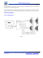
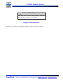
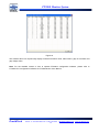
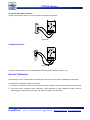
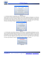
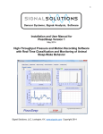
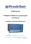
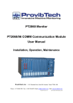
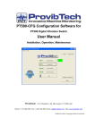
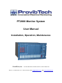
PT2060 Monitor System
User Manual
Installation, Operation, Maintenance
ProvibTech, Inc.
11011 Brooklet Drive, Suite 360, Houston, Texas 77099, USA
Phone: +1-713-830-7601, Fax: +1-281-754-4972, Email: [email protected] , Web: www.provibtech.com
PT2060-SYSTEM -USR-A-12
COPY RIGHT PROVIBTECH 2007
PT2060 Monitor System
Contents
Receiving Inspection and Handling Guide......................................................................................................... 3
Inspection ................................................................................................................................................... 3
Handling and Storing Considerations......................................................................................................... 3
PT2060 Monitor System .................................................................................................................................... 4
PT2060 Monitor System Introduction ......................................................................................................... 4
PT2060 Monitor System Features.............................................................................................................. 4
PT2060 System Components .................................................................................................................... 5
PT2060/80 CM Condition Monitoring Module ............................................................................................ 9
General Information .......................................................................................................................... 10
Field-wiring Diagram ......................................................................................................................... 11
Ordering Information ......................................................................................................................... 14
Back Panel Connectors Layout......................................................................................................... 14
PT2060/98 DISP Display Module............................................................................................................. 15
General Information .......................................................................................................................... 15
Specifications .................................................................................................................................... 15
Field-wiring Diagram ......................................................................................................................... 16
Ordering Information ......................................................................................................................... 17
PT2060/99 System Rack.......................................................................................................................... 17
Specifications .................................................................................................................................... 18
Ordering Information ......................................................................................................................... 19
PT2060 System Configuration Software .................................................................................................. 19
General Information .......................................................................................................................... 19
Ordering Information ......................................................................................................................... 20
PT2060 Monitor Installation............................................................................................................................. 21
Mounting................................................................................................................................................... 21
Module Slot List................................................................................................................................. 21
Rack Module Mounting ..................................................................................................................... 22
Digital Communication ............................................................................................................................. 24
PT2060 Monitor Operation .............................................................................................................................. 25
General Operation Information................................................................................................................. 25
Real-time Value and Status...................................................................................................................... 26
PT2060 Maintenance....................................................................................................................................... 28
General Maintenance Instruction ............................................................................................................. 28
Rack Maintenance.................................................................................................................................... 28
Module Maintenance ................................................................................................................................ 28
LED Check ........................................................................................................................................ 28
Buffered Out Check........................................................................................................................... 29
Verifying Voltage of Back Panel........................................................................................................ 30
General Calibration ........................................................................................................................... 31
ProvibTech
Phone: +1-713-830-7601 Fax: +1-281-754-4972
2
[email protected] , www.provibtech.com
PT2060 Monitor System
Receiving Inspection and Handling Guide
Inspection
Check the devices for possible damage that may have occurred from improper transport. Damages in transit
must be recorded on the transport documents. All claims for damages must be claimed without delay against
the shipper and before the installation.
If no damage is found and the system does not work properly, please check the user manual first. If the
problem can not solve, please contact the ProvibTech office location.
Handling and Storing Considerations
PT2060 should be handled with care during unpacking and installation. Damage to PT2060 is typically
caused by rough handling, shock, or electrostatic discharge (ESD).
Be aware of the following precautions when unpacking and handling PT2060 Rack or any module.
Please have attention about the sharp corners/sides of the rack to avoid any of injuries during the
installation, transporting and un-installation.
All circuit boards and electronic modules associated with this rack contain components which are
susceptible to damage caused by electrostatic discharge. It should be necessary to discharge any static
electricity from yourself and your clothing before handling the rack.
Whenever the module is not installed in a system, always keep it in the protective antistatic bag.
ProvibTech
Phone: +1-713-830-7601 Fax: +1-281-754-4972
3
[email protected] , www.provibtech.com
PT2060 Monitor System
PT2060 Monitor System
PT2060 Monitor System Introduction
PT2060 is ProvibTech’s newly released monitor that
highly reliable, fully digital and modbus ready. PT2060
utilizes the advanced electronics technology and adopt
the concept of programmable logic controller. PT2060
is integrated highly, with high channel density, and
multiple redundancies.
There are two kinds of PT2060 rack: a standard 19″
rack and a 12″ rack. For a standard 19″ rack, it is
capable of supporting up to 48 channels. The PT2060
provides the industry's highest channel density in a
standard 19″ rack. For 12″ rack, it can contain 24
channels at most. PT2060 monitor system uses the
Figure 1
standard PLC logic, it make configuration easy. With full
API 670 compliance, triple channel redundancy and redundancy for power supply inputs, communications
and relay outputs, the PT2060 monitor provides a level of reliability that is unsurpassed.
The newly released PT2060 has both the analog interface with 4-20mA output, Buffered output, Trip-multiply,
Alarm-inhibit, and also digital interface with Modbus connection. Modbus will offer to our customer additional
information such as: sensors status, alarm status, full-scale range, up-level controller changing set-point, gap
voltage, alarm list and system event list. All these are added value to our customer. Let customer better
understanding their system status and better control the system performance.
Easy to Program
The PT2060-CFG is the “easy to use” system configuration software tool used to set up and monitor the
PT2060 system.
Stand Alone or Networked Rack Interconnection
The PT2060 can operate as a single rack or multiple system racks may be networked together via Modbus.
Redundancy
The PT2060 is designed for redundant power supply inputs, relay outputs and communications with an option
for triple redundant channels.
PT2060 Monitor System Features
Fully digital
Highest channel in a standard 19″ rack - 48 channels(12″ rack - 24 channels)
Triple redundant channels
ProvibTech
Phone: +1-713-830-7601 Fax: +1-281-754-4972
4
[email protected] , www.provibtech.com
PT2060 Monitor System
Redundancy for relays, power supply inputs communications
Modbus communication port(RS-232, RS-485, Ethernet port)
Compatible with most sensors and probes (regardless of manufacturer)
Intuitive and easy to configure
Programmable 16 channel relay modules
Programmable 16 channel transmitter modules
Optional local panel display
Standard four channel module
Meet or exceed API670 standard
Integrated condition monitoring module for dynamic and transient data analysis
PT2060 System Components
Model Number
Required system component
There are two sorts of
PT2060 rack: a standard 19″
rack and a 12″ rack
Provides system power to
the PT2060/99 system rack
and all modules installed in
the system rack.
(2)
PT2060/90 Power supply
modules are required for
redundancy
This module provides (1)
active
Modbus
communication port and
Ethernet port, (2) phase
reference channels and
historical buffer for the
PT2060 system rack
This module provides (1)
additional
Modbus
communication port ( either
RS232 or RS485 ) and
Ethernet port, (2) phase
reference channels and
historical buffer for the
PT2060 system rack
This is a touch-panel display
loaded
with
PCM370
vibration analysis system
software
ProvibTech
PT2060/99
PT2060/90
PT2060/91
PT2060/96
PT2060/98
PT2060-CFG
System
Rack
Power
Supply
Module
System
Interface
Module
Display
System
Configuration
Software
●
●
●
●
Comm/
Phase
Reference
Module
Optional
Optional
●
●
●
Phone: +1-713-830-7601 Fax: +1-281-754-4972
5
●
●
[email protected] , www.provibtech.com
PT2060 Monitor System
System
configuration
software tool used to
configure and monitor the
PT2060 system
●
Model Number
Process Signal and Relay Modules
PT2060/10
PT2060/20
PT2060/53
PT2060/40
PT2060/43
Proximity
Seismic
Over speed
Relay
4
4
1*
16
Redundant
Relay
8
Channels per Card
Type of Measurement and (Sensor)
Radial Shaft Vibration (Proximity)
Axial Thrust Position (Proximity)
Rotation Speed (Proximity)
*2
Differential Expansion (Proximity)
Eccentricity (Proximity)
*2
Low Frequency Oscillation (Proximity)
Acceleration (Accelerometer)
Velocity (Accelerometer, Velocity)
Displacement (Velocity , Low Frequency
vibration Displacement Transducer)
Case Expansion (LVDT Sensor)
Over Speed Protection (Proximity and/or
Magnetic Sensor)
●
●**
●
●**
●
●
●
●
●
●
●
●
Relay Output (16 SPDT Relays)
Redundant Relay Output ( 8 DPDT)
Model Number
Process Signal and Transmitter
Modules
Channels per Card
Type of Measurement and (Sensor)
Temperature (RTD)
Temperature (TC)
Process (Voltage Transducer)
Process (Current Transducer)
Transmitter (16 Output Channels)
●
PT2060/31
PT2060/35
PT2060/36
Temperature
Process
Transmitter
8
16
16
●
●
●
●
●
Notes:
* 2 Indicates for this measurement there are only (2) channels per module.
* Indicates that channel 3 and 4 of PT200/53 module can be used as PT2060/10 module channel.
**Indicates that only with one probe option is available.
PT2060/10 PROX Proximity Module
PROX module will condition and process most of the proximity probe input signals. Includes
Radial vibration: Monitoring shaft vibration, single or dual XY.
Thrust position: Monitoring shaft thrust position, with 5/8/11 mm proximity probes.
ProvibTech
Phone: +1-713-830-7601 Fax: +1-281-754-4972
6
[email protected] , www.provibtech.com
PT2060 Monitor System
Eccentricity: Monitoring shaft eccentricity, eccentricity measurements indicate whether rotor eccentricity
is small enough to allow machine startup without causing damage.
Differential Expansion: Monitoring turbine differential expansion.
Low-frequency Vibration: Monitoring low frequency machines. Such as hydro-turbine. Frequency starts
from 0.5Hz to 100Hz.
Speed: Monitoring rotation speed.
Zero Speed: Monitoring rotation speed. When the value is low than a specified value, the monitor will
give the alarm status.
Reverse Rotation Speed: Monitoring rotation of reverse or forward status. When the rotation in the
reverse status, the monitor will give the alarm status immediately.
PT2060/20 SEIS Seismic Module
SEIS module will process most of the seismic input, and some other signals. Then it can output lots of signals,
as follows:
Acceleration and Velocity output: Any current mode seismic sensors (TM0782A, TM0793V etc).
Velocity or Displacement: Any current mode seismic sensors (TM0793V etc).
Low frequency Displacement: Any low frequency sensors (TM079VD etc).
Case Expansion: LVDT differential expansion transducer, this style include paired LVDT input and single
LVDT input.
The module has a build-in integrator that will convert an input accelerometer signal to velocity or a velocity
sensor input into a displacement.
Note: Integrator type can not work in low frequently condition.
PT2060/31 TEMP Temperature Module
TEMP module will process many temperature sensor of RTD input and TC input, Includes
RTD:
PT100 3-wire & 4-wire platinum RTD, (alpha = 0.00385): -200℃ to 850℃
PT100 3-wire & 4-wire platinum RTD, (alpha = 0.00392): -200℃ to 700℃
NI120
3-wire & 4-wire nickel RTD: -80℃ to 260℃
CU10
3-wire & 4-wire copper RTD:-100℃ to 260℃
Type E
Type J
Type K
Type T
-100℃ to 1000℃
-18℃ to 760℃
-18℃ to 1370℃
-160℃ to 400℃
TC:
PT2060/35 PROC Process Module
ProvibTech’s PT2060/35 PROC process module has 16 channels. Each channel on the PT2060/35 PROC
process module can processes the incoming voltage and current sensor signals, Includes
Voltage:
-10 to +10 Vdc input
ProvibTech
Phone: +1-713-830-7601 Fax: +1-281-754-4972
7
[email protected] , www.provibtech.com
PT2060 Monitor System
Current:
4 to 20 mA input
PT2060/36 TRO Transmitter Module
ProvibTech’s PT2060/36 TRO transmitter module has 16 channels. Each channel on the PT2060/36 TRO
transmitter module can be fully programmed to perform needed current output to realize 4 to 20 mA
transmitter output function for other modules. The main task for PT2060/36 TRO transmitter module is to
process the incoming signal and status information, perform the logic and output the appropriate current.
PT2060/40 RELAY Module
RELAY module is a programmable relay module that can be programmed with any status parameters
(alarms/ok) of any channel. The status of all channels can be programmed with ladder logic. The function is
similar to PLC functions. Each RELAY module holds up with 16 relays.
PT2060/43 R-RELAY Redundant- Relay Module
The function is similar to PLC functions. Each R-RELAY module has two independent circuits that work
independently. It performs two-out-of-three voting mode with the three independent alarm signals. When the
system reliability is highly critical, PT2060/43 R-REALY redundant relay module is recommended.
PT2060/53 O-SPEED Over-speed Module
Each O-SPEED module contains one speed channel. Three of the O-SPEED module together with
PT2060/43 redundant relay module compose of an Over-speed protection system. The system takes up total
four slots. PT2060/53 O-SPEED Over-speed module can accept both proximity probe and magnetic pickup
signal input. Channel 3 and channel 4 of PT200/53 module can be used as PT2060/10 module channel.
PT2060/80 CM Condition Monitoring Module
ProvibTech’s PT2060/80 CM condition monitoring module is a 24 channels data collector, and processing
unit. Each of the PT2060/80 modules can accept any signal input from the corresponding signal module,
analyze it, and output it.
PT2060/90 POWER Power Module
POWER module includes two redundant half-height modules. Usually, one half-height power supply module
is sufficient for normal operation. Power supply redundancy can be realized by uses both half-height modules.
PT2060/91 SIM System Interface Module
SIM module has the following function:
System configuration: Configure all the signal channels, system parameters, communication parameters
etc.
Modbus communication: Communicate with PLC/DCS, control system reset, alarm multiply, alarm
inhibit.
Dual phase references: Connect to phase reference proximity probe, and distribute the phase
ProvibTech
Phone: +1-713-830-7601 Fax: +1-281-754-4972
8
[email protected] , www.provibtech.com
PT2060 Monitor System
information over the system.
Rack interconnection with communication.
Virtual address configuration
Ethernet Modbus TCP is required.
Speed output
The System Interface Module collects data from the other modules in the rack over a high-speed internal
network and sends this data to the information system upon request.
The System Interface Module is also able to communicate via Ethernet with host. Host can be Modbus
protocol based or computers with PT2060 Rack Configuration and Data Acquisition software.
PT2060/96 COMM Communication Module
COMM module is a complimentary module in communication with Modbus. It has similar function as the
communication part of SIM. The function and features:
Redundant Modbus communication.
PT2060/96 COMM communication module has been used with the
Modbus connection, as additional communication is required.
Ethernet Modbus TCP is required.
Virtual address configuration.
Upload the other module’s parameter.
Dual phase references.
Speed output.
Signal of phase reference output with peak to peak
Gap voltage output
PT2060/98 DISP Display Module
ProvibTech’s PT2060/98 DISP display system is a powerful touch-panel display loaded with PCM370
vibration analysis system software. The PT2060/98 DISP connects to the PT2060 system via Modbus. The
PCM370 software will collect, store, analyze and display the machinery status data locally or to a wide area
network.
PT2060/99 System Rack
Standard 19″ rack can hold up to 48 channels or total of 12 modules. A 12″ rack can hold up to 24 channels.
PT2060-CFG System Configuration Software
CONFIG software will configure all the modules in the system. It will also configure the system parameters for
interface to up-level PLC/DCS or another rack.
PT2060/80 CM Condition Monitoring Module
ProvibTech
Phone: +1-713-830-7601 Fax: +1-281-754-4972
9
[email protected] , www.provibtech.com
PT2060 Monitor System
General Information
PT2060/80 CM module can realize the following function:
Dynamic data processing
Transient data processing
Interface to PCM360 condition monitoring software and database system
Each PT2060/80 CM module can process up to 24 channels of input signal and 2 channels of phase
reference signal. When there is no pt2060/91 module in the PT2060 rack, the phase reference output
channels of PT2060/80 module can not be used. A standard 19″ PT2060 rack can hold up to two PT2060/80
CM modules. PT2060/80 CM module in left slot can receive the signal that come from signal module slot1-6,
and the right one supports slot7-12. User can choose one PT2060/80 CM module or two as requirement. A
12″ PT2060 rack can contain one PT2060/80 CM module only.
PT2060/80 receives signal through internal bus of the rack. Every Slot of the rack has 4 channels of analog
signal connected to PT2060/80 CM module through internal bus. Four channels in slot 1 of the 19″ rack are
corresponding with 1-4 channels of PT2060/80 CM module installed in the slot 13; Four channels in slot 2 are
corresponding with 5-8channels of PT2060/80 CM module installed in the slot 13, and the same, four
channels in slot 6 are corresponding with channels 21-24 of PT2060/80 CM module installed in the slot 13;
Four channels of slot 7 are corresponding with channels 25-28 of PT2060/80 CM module installed in the slot
14, while four channels in of slot 8 are corresponding with channels 29-32 of PT2060/80 CM module installed
in the slot 14. And then, four channels of slot 12 are corresponding to channels 45-48 of PT2060/80 CM
module installed in the slot 14. Four channels in slot 1 of 12″ rack are corresponding with channels 1-4 of
PT2060/80 CM module installed in the slot 7, while four channels in slot 2 are corresponding with channels
5-8 of PT2060/80 CM module installed in slot 7. And then, four channels in slot 6 are corresponding with
21-24 channels of PT2060/80 CM module installed in slot 7.
One slot of the PT2060 rack will be used by PT2060/31 module, if there is a PT2060/31 module in the rack,
and there is no initial signal connected to PT2060/80 CM module. Four channels of PT2060/80 module
corresponding to the slot that 31 module installed in will not be used though 31 module has 8 channels. As the
same to PT2060/31, four channels of 80 CM module corresponding to PT2060/35/36/40/43 module will not be
used. Also, four channels of PT2060/80 CM module corresponding to PT2060/96 module will not be used too.
For example, if PT2060/31 is installed in slot 5, channels 17-20 of PT2060/80 CM module in slot 13 (slot 7 for
12″ rack) corresponding to slot 5 will not be used.
ProvibTech recommend that the modules needed for condition monitoring are put on the left of the rack near
to slot 1 as possible as you can. As possible as you can, put PT2060/31/35/36/40/43/96 modules on the right
of the modules which need condition monitoring. This can reduce the number of PT2060/80 CM module.
To the maximum, the two wire terminals of every PT2060/80 CM module can output 24 channels of analog
signal and 2 channels of phase reference signal. The top terminal outputs analog signals of 1-12 channels
and 2 channels of phase reference signal, while the terminal below outputs analog signals of 13-24 channels
and 2 channels of phase reference signal. The signal output amplitude of PT2060/80 CM module is about half
ProvibTech
Phone: +1-713-830-7601 Fax: +1-281-754-4972
10
[email protected] , www.provibtech.com
PT2060 Monitor System
of the original signal output by sensor. If sensor original signal is needed, please connect the output signal of
BNC terminal on the front panel of the module.
The main purpose of GP for PT2060/80 CM module is to make users conveniently to connect other condition
monitoring system. Please refer to the following wiring diagram for the definition of wire connection terminal.
Field-wiring Diagram
Connect to PCM360 System
CH1-CH12
PT2060-008003-A03
CH13-CH24
PT2060-008003-A03
CH25-CH36
PT2060-008003-A03
CH37-CH48
PT2060-008003-A03
Figure 2
ProvibTech
Phone: +1-713-830-7601 Fax: +1-281-754-4972
11
[email protected] , www.provibtech.com
PT2060 Monitor System
Connect to GP
Connection Diagram
32
31
speed
26
25
24
23
X axial vibration
Y axial vibration
18
17
axail displacement
16
15
eccentricit
phase reference
4
3
2
1
32
31
speed
26
25
24
23
X axial vibration
Y axial vibration
18
17
axail displacement
16
15
eccentricit
phase reference
4
3
2
1
Figure 3
Dimension of GP
GP is a general port transform tool. One port of it can connect to PT2060-008000 data wire, and the other port
can connect to other system or equipment. It can be fixed on the DIN rail.
The signal come from PT2060/80 CM module enter into one GP port and go out by the other port, but it is
without any changes.
ProvibTech
Phone: +1-713-830-7601 Fax: +1-281-754-4972
12
[email protected] , www.provibtech.com
PT2060 Monitor System
Figure 4
Figure 5 Top View of GP
Figure 6 Bottom View of GP
ProvibTech
Phone: +1-713-830-7601 Fax: +1-281-754-4972
13
[email protected] , www.provibtech.com
PT2060 Monitor System
Ordering Information
PT2060/80-AX
AX: Back-panel IO module
A0: Basic IO module for standard 19″ Rack
A1: Basic IO module for standard 12″ Rack
Optional Accessories:
PT2060-008000-AXX: Cable
It connects PT2060/80 CM to PCI6013 DAQ card or GP.
A00
2 meters
(6.6 feet)
A01
10 meters
(32.8 feet)
PT2060-008001: GP for PT2060/80 CM module
It is a special tool of port transform. If PT2060/80 CM module can’t connect with other equipment by
PT2060-008000 data wire directly, GP will be used.
PT2060-008003-AXX: Cable
It connects PT2060/80 CM to PCI6220 or PCI6250 DAQ card.
A00
2 meters
(6.6 feet)
A01
10 meters
(32.8 feet)
Back Panel Connectors Layout
Figure 7
ProvibTech
Phone: +1-713-830-7601 Fax: +1-281-754-4972
14
[email protected] , www.provibtech.com
PT2060 Monitor System
PT2060/98 DISP Display Module
General Information
ProvibTech’s PT2060/98 DISP display system is a powerful touch-panel display loaded with PCM370
vibration analysis system software. The PT2060/98 DISP connects to the PT2060 system via Modbus. The
PCM370 software will collect, store, analyze and display the machinery status data locally or to a wide area
network.
ID each channel, and arrange the routing
Setup data collection strategy
Display machine photo and real-time data and status on top of the photo
Real-time bar graph/ status list/ alarm status of each channel
Alarm events
Trend plot on each channel
Touch-panel for easy operation
Network to control systems (PLC/DCS or Historian) via Modbus
The figure below gives an interface of PCM370 For PT2060 software.
Figure 8
Specifications
Electrical
Touch Screen PC power supply:
100 - 240 VAC @ 50 ~ 60 Hz, 4 - 2 A
Physical
Touch panel, color 15″ PC
Mounting size:
Front Panel:450 x 315.6 x 6 mm
Control Box:422.4 x 219.4 x 97/112.2 mm
Cut out Dimension:428 x 297 mm
ProvibTech
Phone: +1-713-830-7601 Fax: +1-281-754-4972
15
[email protected] , www.provibtech.com
PT2060 Monitor System
Figure 9 Panel Cut-out Dimensions: 428×297mm
Field-wiring Diagram
Connect with PT2060/91 COMM Module via Ethernet
PT2060/98 Touch Panel
SYSTEM
INTERFACE
91 SIM
ETHERNET
RS485
PT2060-009105-A00
PCM370 for PT2060
NC
ARM
NO
COM
RS232
Connect to the LAN port of PT2060/98
SHIELD
Figure 10
ProvibTech
Phone: +1-713-830-7601 Fax: +1-281-754-4972
16
[email protected] , www.provibtech.com
PT2060 Monitor System
Connect with PT2060/96 COMM Module via RS232
PT2060/98 Touch Panel
SYSTEM
COMMUNICATION
96 COMM
ETHERNET
RS485
PCM370 for PT2060
RS232
PT2060-009107-A00
SHIELD
Figure 11
Ordering Information
Warning: Only work with PT2060/91 or PT2060/96 module
PT2060/98-BX
BX: Touch panel with PCM370 for PT2060 software
B0: No touch panel (only include PCM370 for PT2060 software)
B1: IPPC-6152A-ROAE 15″ Touch panel with 100 - 240 VAC power (include two power cables, a
RS232 cross cable PT2060-009107 and a cross Ethernet cable PT2060-009105)
Optional Accessories:
PT2060-009800: HP dvd1040e external DVD writer
PT2060-009801: Windows XP English version
PT2060/99 System Rack
There are two sorts of PT2060 rack: a standard 19″ rack and a 12″ rack.
The standard 19″ rack is a rack with the same dimensions as a standard 19″ industrial rack.
ProvibTech
Phone: +1-713-830-7601 Fax: +1-281-754-4972
17
[email protected] , www.provibtech.com
PT2060 Monitor System
Specifications
Environmental
Temperature:
Operation:
-20℃ ~ +65℃
Storage:
-40℃ ~ +85℃
Humidity:
95% non-condensing
Physical
A 19″ standard rack has 16 slots. A 12″ rack has 9 slots.
Figure 12
A 19″ standard rack mount, dimensions, please refer to the figure above. All data list below:
1. 483mm (19.0″)
2. 266mm (10.5″)
3. 355mm (14.0″)
4. 246mm (9.7″)
5. 442mm (17.4″)
6. 465mm (18.3″)
7. 190mm (7.5″)
12″ rack is similar to the 19″ standard rack, some data are different only. The data list below:
1. 305 mm (12.0″)
ProvibTech
Phone: +1-713-830-7601 Fax: +1-281-754-4972
18
[email protected] , www.provibtech.com
PT2060 Monitor System
2.
3.
4.
5.
6.
7.
266mm (10.5″)
355mm (14.0″)
246mm (9.7″)
264mm (10.4″)
287mm (11.3″)
190mm (7.5″)
Ordering Information
PT2060/99-AX:
A0: Standard 19″ rack
A1: Standard 12″ rack
Optional Accessories:
PT2060-009900: Plastic frame for 19″ Rack
PT2060-009901: Plastic frame for 12″ Rack
PT2060-009902: Rack cover for 19″ Rack
PT2060-009903: Rack cover for 12″ Rack
PT2060-009904: Bolt for all front panel
PT2060-009905: Front blank panel
PT2060-009906: Back blank panel
Figure 13
PT2060 System Configuration Software
PT2060 System Configuration software is an important part of PT2060 monitor system. Via the software,
PT2060 parameters are configured and the running status is displayed.
General Information
The figure below is the main rack window of the software. There are seven main items in the window.
ProvibTech
Phone: +1-713-830-7601 Fax: +1-281-754-4972
19
[email protected] , www.provibtech.com
PT2060 Monitor System
Figure 14
Ordering Information
PT2060-CFG-AX
A0: Configuration software CD include USB to RS232 converter driver
User Manual
ProvibTech
Phone: +1-713-830-7601 Fax: +1-281-754-4972
20
[email protected] , www.provibtech.com
PT2060 Monitor System
PT2060 Monitor Installation
Mounting
Module Slot List
Standard 19″ Rack
No redundancy
Redundancy*
PT2060/10
Slot 1-12
Slot 1-3, Slot 5-7, Slot 9-11
PT2060/20
PT2060/31
PT2060/35
PT2060/36
PT2060/53
PT2060/40
PT2060/43
PT2060/80
PT2060/91
PT2060/96
PT2060/90
Slot 1-12
Slot 1-3, Slot 5-7, Slot 9-11
Slot 1-12
---------
Slot 1-12
---------
Module number
Slot 1-12
---------
---------
Slot 1-3, Slot 5-7, Slot 9-11
Slot 1-12
---------
---------
Slot 4, 8, 12
Slot 13, 14 (back only)
---------
Slot 15
---------
Slot 1-12
---------
Slot 16 (Comment redundancy strongly)
Slot 16 (Double PT2060/90, up and down)
* For redundancy, all signal modules must be installed in adjacent slots.
Standard 12″ Rack
Module number
PT2060/10
PT2060/20
PT2060/31
PT2060/35
PT2060/36
PT2060/53
PT2060/40
PT2060/43
PT2060/80
PT2060/91
PT2060/96
PT2060/90
No redundancy
Redundancy*
Slot 1-6
Slot 1-3
Slot 1-6
Slot 1-3
Slot 1-6
---------
Slot 1-6
---------
Slot 1-6
---------
---------
Slot 1-3
Slot 1-6
---------
---------
Slot 4
Slot 7 (back only)
---------
Slot 8
---------
Slot 1-6
---------
Slot 9 (Comment redundancy strongly)
Slot 9 (Double PT2060/90, up and down)
* For redundancy, all signal modules must be installed in adjacent slots.
ProvibTech
Phone: +1-713-830-7601 Fax: +1-281-754-4972
21
[email protected] , www.provibtech.com
PT2060 Monitor System
Rack Module Mounting
Front-panel Mounting
There is a front-panel picture of 19″ rack below. The first and second slots from left have no modules. We can
see the bus PCB board directly. One slot has two connectors like that. Every front-panel module must connect
to its connectors tightly.
Figure 15
1.
Insert the module into corresponding slot as the figure below.
Figure 16
2.
3.
4.
Push the module firmly into the slot, make sure the two connectors been connected to the corresponding
connectors on the bus PCB board.
Fasten the screws on top and bottom of the front–panel. A screwdriver is necessary.
Verify if the module is secure after the module installed.
Back-panel Mounting
There is a back-panel picture of 19″ rack below. Several slots on right have no modules. We can see the bus
ProvibTech
Phone: +1-713-830-7601 Fax: +1-281-754-4972
22
[email protected] , www.provibtech.com
PT2060 Monitor System
PCB board directly. One slot has two connectors like that. Every back-panel module must connect to its
connectors tightly. Back-panel must match its front-panel.
Figure 17
1.
Insert the module into corresponding slot.
Figure 18
2.
Push the module firmly into the slot, make sure the two connectors been connected to the corresponding
connectors on the bus PCB board. See figure below.
Figure 19
3.
4.
Fasten the screws on top and bottom of the back–panel. A screwdriver is necessary.
Verify if the back panel is secure after the module is installed.
ProvibTech
Phone: +1-713-830-7601 Fax: +1-281-754-4972
23
[email protected] , www.provibtech.com
PT2060 Monitor System
Warning
The metal frame must be earth grounding. Otherwise,
high voltage may exist on the rack frame.
Digital Communication
Please refer to PT2060/91 SIM system interface module user manual for detail.
ProvibTech
Phone: +1-713-830-7601 Fax: +1-281-754-4972
24
[email protected] , www.provibtech.com
PT2060 Monitor System
PT2060 Monitor Operation
General Operation Information
According to the information of PT2060 Monitor Installation to connect the PT2060 rack, open the
configuration software to upload all the information.
Figure 20
The figure above is the PT2060 System Configuration interface. It shows all the modules which is inserted
into PT2060’s rack.
For more information, please click the module picture available on the rack interface, user can get
configuration setting window and do the modules parameters viewing or modification. More detailed operation
information, please refer to PT2060-CFG Configuration Software for PT2060 Monitor User Manual.
If the communication wasn’t set up auto, click “Communication->Communication Setup” to set up the
parameters:
图 21
If communication establishment succeed, click the button Configure to open the window Communication
Parameter to alter it. Set the parameters and download the setting to the PT2060. Default setting:
Baud rate: 19200
ProvibTech
Phone: +1-713-830-7601 Fax: +1-281-754-4972
25
[email protected] , www.provibtech.com
PT2060 Monitor System
Stop bit: 2
Parity: None
Figure 22
Click the button Connect to open the window Communication Setting. Enter correct ID(Slave address,1 for
default setting). Select the right port number to communicate.
Following the procedure to obtain the COM port number: “My PC -> Property -> Device Manager - >
Hardware -> Ports”. See more details in the previous section.
Make sure that the PT2060-CFG only connects to one PT2060.
Enter correct Rack address ID (default value is 1).
Click “Auto Scan”or “Scan” button to uploaded communication parameters..
Real-time Value and Status
Affirming the parameters what are configured, if they are very proper, then click “Status/Event -> Real-Time
Value And Status”, the figure as below:
Figure 23
Then will display the figure of Real-time and Value And Status in the below figure.
ProvibTech
Phone: +1-713-830-7601 Fax: +1-281-754-4972
26
[email protected] , www.provibtech.com
PT2060 Monitor System
Figure 24
This window above can dynamically display monitored real-time value, alarm status, gap not ok status and
gap voltage value.
Note: For the detailed content of how to operate PT2060’s configuration software, please refer to
PT2060-CFG Configuration Software for PT2060 Monitor User Manual.
ProvibTech
Phone: +1-713-830-7601 Fax: +1-281-754-4972
27
[email protected] , www.provibtech.com
PT2060 Monitor System
PT2060 Maintenance
General Maintenance Instruction
The boards inside of PT2060 modules cannot be repaired in the field. Maintaining a PT2060 rack consists of
rack maintenance and module maintenance.
The maintenance interval is very important for the PT2060 monitor system maintenance. Usually, a yearly
maintenance is sufficient. If it works in extraordinary circumstance, user should shorten the interval according
to the actual situation.
Extraordinary circumstance means that
PT2060 is used to monitor some critical equipment
PT2060 works in high temperature, high humidity, and corrosive environment
Besides, maintenance interval should be adjusted according to plant maintenance period.
Rack Maintenance
There is something must to do.
1. Power off the PT2060, demount it from the equipment and transfer it to a workbench.
2. Check every module and every screw on rack, if any looseness is found, fasten it again. This job is
important.
3. Check all power wires, and ensure their safety.
Module Maintenance
Module maintenance is done to verify that the module operates correctly. There are many jobs must to do,
LED check, BUF check and voltage check are introduced simply in this section. More check means and more
detailed job, please refer to each module user manual.
LED Check
PT2060/10/20/31/35/53 Signal Process Modules
LED
On/Flashing
OK Off/Not flashing
Trouble solution
OK/IO
Normally working
(communicating)
ALARM
Alarm state
BYPASS
Bypass state
Module failure
Communication failure
Driver failure
Cable connection wrong,
short or open.
Probe is not properly gapped
Well connect module with
rack again.
Restart system.
Check probe driver and
cable.
ProvibTech
Phone: +1-713-830-7601 Fax: +1-281-754-4972
28
[email protected] , www.provibtech.com
PT2060 Monitor System
PT2060/40/43 Relay Modules
LED
On/flashing
OK
Normally working
CH1~CH16
Relay energized
OK, TX/RX
Off/Not flashing
Trouble solution
Well connect module with
rack again.
Restart system.
Module failure
Communication failure
PT2060/90 POWER Power Supply Modules
LED
OK
Constant on
Normally working
Off
Normal trouble solution
Power-up
Check input wire
Use back-up module or
connect with ProvibTech
engineers
Power-down
Wiring failure
Module failure
PT2060/91 SIM System Interface Module
LED
OK
On/flashing
Normally working
ALM_MLT
Alarm-multiple state
BYPASS
Alarm-bypass state
CONFIG
Configuration
OK Off/Not flashing
Module failure or
Communication failure
Phase reference not OK
Trouble solution
or
Well connect module with
rack again.
Check probe driver and
cable of Phase reference.
PT2060/36/96 Module
LED
OK
On/flashing
Normally working
OK Off/Not flashing
Module failure or
Communication failure
Trouble solution
Well connect module with
rack again.
Buffered Out Check
Once PT2060 fail to work as usual, user can do a simple test to see if the problem comes from board.
Using the oscilloscope to test Buffered Output signal, and see whether signal is the corresponding with added
one, please refer to below picture.
ProvibTech
Phone: +1-713-830-7601 Fax: +1-281-754-4972
29
[email protected] , www.provibtech.com
PT2060 Monitor System
Figure 25
The noise signal PK-PK value should be less than 50mV. When test, please connect GND of oscilloscope to
GND of testing Channel.
Verifying Voltage of Back Panel
PT2060/10 Back Panel
Back panel voltage value measured with multimeter without connecting transducers. It is about -24 V for PWR
and COM.
PWR
COM
SIG
SHD
PWR
COM
SIG
SHD
C
H
1
C
H
2
Figure 26
PT2060/20 Back Panel
Connected with Seismic Transducer
When seismic transducers are connected, please test the power as shown in the figure below, channel
current should be at about 4.00mA.
PWR
COM
SIG
SHD
PWR
COM
SIG
SHD
C
H
1
C
H
2
Figure 27
ProvibTech
Phone: +1-713-830-7601 Fax: +1-281-754-4972
30
[email protected] , www.provibtech.com
PT2060 Monitor
Connected with LVDT Transducer
Voltage value is about 19V for connection PWR and COM on back panel.
PWR
COM
SIG
SHD
PWR
COM
SIG
SHD
C
H
1
C
H
2
Figure 28
PT2060/91 Back Panel
SHIELD
Figure 29
As picture above indicating of two phases input terminals, measured value is about -24V.
General Calibration
If the linearity of some channels does not satisfy the requirement, user could re-calibrate these channels.
4-20mA Current calibration, follows these steps.
1. Connect a multimeter to the current output port in serial. Plug Red pen into OUT and black pen into COM.
2. Click menu item Calibration->User Calibration, enter password to open calibration window. See the
following figure. Select the slot number and channel number to be calibrated.
ProvibTech
Phone: +1-713-830-7601 Fax: +1-281-754-4972
31
[email protected] , www.provibtech.com
PT2060 Monitor
Figure 30
3. The whole procedure is implemented in the 4-20mA Calibration.
Click the button Full-scale low(Zero) Calibration to open the zero calibration window(figure 31). Follow the
steps showed in the window to implement calibration. First, click the button Start Calibration in step1. Wait till
the multimeter outputs a right value, then read the output current value from multimeter after it settled down.
Enter this value (three significant decimal digits) into the text area in step2. After that, click the button
Full-scale low Calibration in step3 to download. Click Exit to exit the zero calibration.
Figure 31
4. Click the button Full-scale high Calibration. Click OK button in the WARNING window(figure 32). Enter
YES in the Warning dialogue (figure 33) and click OK to open the calibration window(figure 34). Follow the
steps showed in the window to implement calibration. First, click the button Start Calibration in step1, Wait till
the multimeter outputs a right value, then read the output current value from multimeter after it settled down.
Enter this value (three significant decimal digits) into the text area in step2. After that, click the button
Full-scale high Calibration in step3 to download. Click Exit to exit the high calibration.
Figure 32
ProvibTech
Phone: +1-713-830-7601 Fax: +1-281-754-4972
32
[email protected] , www.provibtech.com
PT2060 Monitor
Figure 33
Figure 34
5. Click the button Exit to go back to the RUN state. You could optionally do linearity test again to check the
calibrating result. If you does not satisfy, you could redo it.
ProvibTech
Phone: +1-713-830-7601 Fax: +1-281-754-4972
33
[email protected] , www.provibtech.com