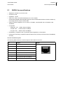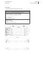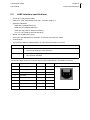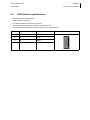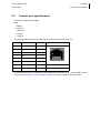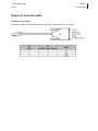
1
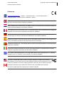
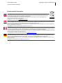
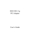
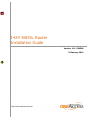
1424 SHDSL Router
Installation Guide
Version: 1.8 - 554584
23 January 2012
1424 SHDSL Router
Copyright, safety and statements ii
User and reference manual
Document properties
Subject
1424 SHDSL Router
Manual type
Installation Guide
Version
1.8
Code
554584
Modification date
23 January 2012 ©OneAccess
Copyright notice
The information and descriptions contained in this publication are the property of OneAccess. Such information and descriptions must not be copied or reproduced by any means, or disseminated or distributed
without the express prior written permission of OneAccess.
This publication could include technical inaccuracies or typographical errors, for which OneAccess never
can or shall be held liable. Changes are made periodically to the information herein; these changes will
be incorporated in new editions of this publication. OneAccess may make improvements and/or changes
in the product(s) described in this publication at any time, without prior notice.
Safety requirements
Carefully read the safety instructions, installation precautions and connection precautions as stated in
chapter 2 - Installing and connecting the 1424 SHDSL Router on page 10.
1424 SHDSL Router
Copyright, safety and statements iii
User and reference manual
Statements
www.oneaccess-net.com → Support → Download Center → Technical Downloads →
Choose a product → Choose product certificates→ Search
Hereby, OneAccess declares that this 1424 SHDSL Router complies with the essential requirements
and other relevant provisions of Directive 1999/5/EC.
Hierbij verklaart OneAccess dat deze 1424 SHDSL Router overeenstemt met de essentiële vereisten en
andere relevante bepalingen van Richtlijn 1999/5/EC.
Par la présente, OneAccess déclare que ce 1424 SHDSL Router est en conformité avec les exigences
essentielles et autres articles applicables de la Directive 1999/5/EC.
Hiermit, OneAccess erklärt daß dieser 1424 SHDSL Router in Fügsamkeit ist mit den wesentlichen
Anforderungen und anderen relevanten Bereitstellungen von Direktive 1999/5/EC.
Mediante la presente, OneAccess declara que el 1424 SHDSL Router cumple con los requisitos esenciales y las demás prescripciones relevantes de la Directiva 1999/5/CE.
A OneAccess declara que o 1424 SHDSL Router cumpre os principais requisitos e outras disposições
da Directiva 1999/5/EC.
Col presente, OneAccess dichiara che questo 1424 SHDSL Router è in acquiescenza coi requisiti
essenziali e stipulazioni attinenti ed altre di Direttivo 1999/5/EC.
Με το παρόν η OneAccess δηλώνει ότι το 1424 SHDSL Router είναι συμμορφούμενο με τις βασικές
απαιτήσεις και με τις υπόλοιπες σχετικές διατάξες της οδηγίας 1999/5/EC.
This device complies with Part 15 of the FCC Rules. Operation is subject to the following
two conditions: (1) this device may not cause harmful interference, and (2) this device must
accept any interference received, including interference that may cause undesired operation.
Cet appareil numérique de la classe A est conforme à la norme NMB-003 du Canada.
This Class A digital apparatus complies with Canadian ICES-003.
1424 SHDSL Router
Copyright, safety and statements iv
User and reference manual
Environmental information
The crossed-out wheeled bin means that within the European Union the product must be taken to separate
collection at the product end-of-life. This applies to the device but also to any accessories marked with this symbol.
Do not dispose of these products as unsorted municipal waste.
If you need more information on the collection points where you can present your end-of-life equipment for
recycling, please contact your local importer.
For Belgium, you can contact [email protected].
De doorstreepte container wil zeggen dat binnen de Europese gemeenschap het product voor gescheiden afvalverzameling moet
worden aangeboden aan het einde van de levensduur van het product. Dit geldt voor het toestel, maar ook voor alle toebehoren
die van dit symbool voorzien zijn. Bied deze producten niet aan bij het gewone huisvuil.
Indien u meer informatie wenst over het inzamelpunt waar u afgedankte apparatuur kan aanbieden voor recyclage, gelieve dan
uw lokale importateur te contacteren.
Voor Belgie kan u contact opnemen met [email protected].
Le symbole de la poubelle sur roues barrée d'une croix signifie que ce produit doit faire l'objet d'une collecte sélective en fin de vie
au sein de l'Union Européenne. Cette mesure s'applique non seulement à votre appareil mais également à tout autre accessoire
marqué de ce symbole. Ne jetez pas ces produits dans les ordures ménagères non sujettes au tri sélectif.
Si vous souhaitez plus d'information concernant le point de collecte où vous pouvez apporter vos appareils usagés afin qu'ils soient
recyclés, veuillez contacter votre importateur local.
Pour la Belgique, vous pouvez prendre contact avec [email protected].
Das Symbol der durchgestrichenen Abfalltonne auf Rädern bedeutet dass das Produkt in der Europäischen Union einer
getrennten Mülsammlung zugeführt werden muss. Dies gilt sowohl für das Produkt selbst, als auch für alle mit diesem Symbol
gekennzeichneten Zubehörteile. Diese Produkte dürfen nicht über den unsortierten Hausmüll entsorgt werden.
Falls Sie weitere Auskünfte brauchen im Betracht der Sammelplätze für ausrangierte Apparate, wenden Sie sich bitte an Ihren
örtlichen Importeur.
Für Belgien, bitte kontaktieren sie [email protected].
1424 SHDSL Router
Preface v
User and reference manual
Documentation set
For all devices, the documentation set currently consists of the following:
Document
Description
1424 SHDSL Router installation guide
This is this document, it shows you how to install and connect the
1424 SHDSL Router.
TDRE manual
The user part of the TDRE manual explains how to configure a device
and provides information about all features that can be configured in
TDRE, i.e. encapsulations, routing, bridging, QoS, tunnels, IPSEC, ...
The reference part of the TDRE manual contains a complete description of all the configuration, status, performance and alarm parameters for look-up purposes.
The proxy management (also called Orchid function) parameters are
described in the Orchid function manual.
Maintenance tools user manual
The 1424 SHDSL Router can be maintained and managed by a variety of maintenance and management tools.
The Maintenance tools user manual describes these tools.
Refer to the installation guides of the OneAccess devices, for an introduction on these tools.
TMA Quick Start Guide
This guide briefly highlights the Total Maintenance Application or
TMA
All these documents, together with the free maintenance tool TMA and the firmware of the TDRE
devices, can be found on the OneAccess Products distribution CD that is delivered with all TDRE products.
1424 SHDSL Router
Preface vi
User and reference manual
Organisation of this installation guide
This manual contains the following main parts:
Part
This part …
Installation guide
shows you how to install and connect the 1424 SHDSL Router. It also explains
how to connect to the 1424 SHDSL Router on the pc.
Annex
gives some additional information.
Refer to the Table of contents on page 1 for a detailed overview of this manual.
Typographical conventions
The following typographical conventions are used in this manual:
The format …
indicates …
Normal
normal text.
Italic
•
new or emphasised words
•
application windows, buttons and fields. E.g. In the Filename field enter …
Blue
references to other parts in the manual.
E.g. “Refer to xx - Title for more information”.
Blue underline
•
a hyperlink to a web site. E.g. www.oneaccess-net.com
•
a reference to another manual. E.g. “Refer to the TMA manual (PDF) for
more information”. The abbreviation between brackets is an indication of the
file format (PDF = Portable Document Format / CHM = Compiled HTML
Help).
Graphical conventions
The following icons are used in this manual:
Icon
Name
This icon indicates …
Remark
remarks or useful tips.
Caution
text to be read carefully in order to avoid damage to the device.
1424 SHDSL Router
Preface vii
User and reference manual
TDRE
The Total Dynamic Routing Engine (TDRE) is a feature-rich operating system that guarantees a common feature set across the different OneAccess product lines and a uniform support by maintenance
and management tools.
Audience
This manual is intended for computer-literate people, who have a working knowledge of computing and
networking principles.
Your feedback
Your satisfaction about this purchase is an extremely important priority to all of us at OneAccess. Accordingly, all electronic, functional and cosmetic aspects of this new unit have been carefully and thoroughly
tested and inspected. If any fault is found with this unit or should you have any other quality-related comment concerning this delivery, please submit the Quality Comment Form on our web page at
www.oneaccess-net.com → Support → Quality Comment Form.
1424 SHDSL Router
Table of contents 1
User and reference manual
Table of contents
Installation guide.................................................................................... 1
1
Introducing the 1424 SHDSL Router ..................................................................2
1.1
1.2
1.3
1.4
2
Installing and connecting the 1424 SHDSL Router ........................................10
2.1
2.2
2.3
2.4
2.5
2.6
2.7
2.8
3
General description .................................................................................................... 3
1424 SHDSL Router family overview ......................................................................... 4
Maintenance and management tools ......................................................................... 5
Maintenance and management tools connection possibilities ................................... 9
Safety instructions / Consignes de sécurité ............................................................. 11
Unpacking ................................................................................................................ 13
Selecting a site ......................................................................................................... 14
Mounting the 1424 SHDSL Router on a wall............................................................ 15
Connection precautions............................................................................................ 17
Connecting the 1424 SHDSL Router ....................................................................... 18
The front panel LED indicators................................................................................. 24
Powering up the 1424 SHDSL Router...................................................................... 27
DIP switches of the 1424 SHDSL Router .........................................................28
3.1
3.2
The 1424 SHDSL Router motherboard .................................................................... 29
Opening and closing the housing ............................................................................. 30
4
TMA sub-system picture ...................................................................................32
5
Technical specifications ...................................................................................34
5.1
5.2
5.3
5.4
5.5
5.6
5.7
5.8
5.9
5.10
5.11
5.12
SHDSL line specifications ........................................................................................ 35
LAN1 4 port Ethernet switch specifications .............................................................. 37
LAN2 interface specifications ................................................................................... 38
USB interface specifications..................................................................................... 39
Console port specifications ...................................................................................... 40
Memory specifications.............................................................................................. 41
Power requirements ................................................................................................. 42
Dimensions............................................................................................................... 43
Safety compliance .................................................................................................... 44
Over-voltage and over-current protection compliance ............................................. 44
EMC compliance ...................................................................................................... 44
Environmental compliance ....................................................................................... 45
Annex .................................................................................................... 46
Annex A:Console cable ...........................................................................................47
Index ........................................................................................................ 1
1424 SHDSL Router 1
User manual
Installation guide
1424 SHDSL Router
User manual
1
Chapter 1 2
Introducing the 1424 SHDSL Router
Introducing the 1424 SHDSL Router
This chapter gives an introduction to the 1424 SHDSL Router. The following gives an overview of this
chapter:
•
1.1 - General description on page 3
•
1.2 - 1424 SHDSL Router family overview on page 4
•
1.3 - Maintenance and management tools on page 5
•
1.4 - Maintenance and management tools connection possibilities on page 9
1424 SHDSL Router
User manual
1.1
Chapter 1 3
Introducing the 1424 SHDSL Router
General description
The 1424 SHDSL Router is a secure SHDSL router for high bandwidth applications. The SHDSL multipair interface offers a bandwidth up to 22Mbps over up to 4 copper pairs.
High speed DSL access
The 1424 SHDSL Router includes a high speed symmetrical bandwidth in various DSL networks and at
various local loop distances. It includes a SHDSL.bis interface with up to 4 copper pairs. This provides
line rates up to 22Mbps on short distances and up to 10Mbps on operator standard loop lengths. The
various pair bonding techniques make it suitable for any type of DSL infrastructure. The 1424 SHDSL
Router supports both ATM and EFM modes in single and multipair topologies.
High network availability
A dedicated Ethernet interface is available as a backup when the DSL network is not available. Traffic
is automatically routed to the available network. Alternatively this interface can be used for a DMZ zone
(De-Militarised Zone).
Ethernet services
The 1424 SHDSL Router relies on the robust TDRE software, the OneAccess Bridging and Routing
Engine offering advanced layer 2 and layer 3 functions. Ethernet functionalities include Spanning Tree
Protocol, multiple bridge groups and VLAN features such as tagging, switching, QinQ, COS/TOS and
TOS/COS mapping and Ethernet QoS. VLANs and ATM PVCs have the status and statistics characteristics of a physical interface.
Full service router
On IP level, the equipment implements different routing protocols such as RIP, OSPF and BGP-4 and
Policy based routing. The 1424 SHDSL Router provides secured Internet access through a stateful
inspection firewall. The business applications can be used based on central databases through IP VPNs.
For this purpose, advanced VPN functions such as L2TP, GRE and IPSec with encryption are standard
included. It provides best-in-class IP Quality of Service features including real-time processing of high
priority, delay sensitive applications and guaranteed bandwidth for selected flows.
Accelerated deployment and service provisioning
As all TDRE routers, the 1424 SHDSL Router is manageable through a variety of maintenance and management tools. These include:
•
A free graphical user interface for local or remote maintenance.
•
A customisable Web-configuration utility.
•
A CLI to facilitate scripting.
•
Easy integration into TMA Element Management.
Technicians or the customer install the units with a standard configuration. Once connected to the network the 1424 SHDSL Router automatically retrieves all customer specific information from the service
provider’s databases and thus becomes ready for the service.
USB interface
On some versions of the 1424 SHDSL Router, a USB interface is present. The USB interface is USB 2.0
compliant. It can be used to connect a mobile USB device for backup of the DSL connection over the
mobile 3G network.
1424 SHDSL Router
Chapter 1 4
User manual
1.2
Introducing the 1424 SHDSL Router
1424 SHDSL Router family overview
RAM
Flash
USB interface
Ethernet ports
SHDSL line pairs
Standard
version
The following gives an overview of the 1424 SHDSL Router versions:
1424 SHDSLbis 1P
1
1+4
-
64MB
32MB
1424 SHDSLbis 2P
2
1+4
-
64MB
32MB
1424 SHDSLbis 4P
4
1+4
-
64MB
32MB
1424 SHDSLbis 1P U
1
1+4
1
64MB
32MB
1424 SHDSLbis 2P U
2
1+4
1
64MB
32MB
1424 SHDSLbis 4P U
4
1+4
1
64MB
32MB
1424 SHDSL Router
User manual
1.3
Chapter 1 5
Introducing the 1424 SHDSL Router
Maintenance and management tools
This section gives a quick overview of the various maintenance and management tools that can be used
to manage the 1424 SHDSL Router.
The following gives an overview of this section:
•
1.3.1 - Overview of various tools on page 6
•
1.3.2 - Upgrading the software on page 8
1424 SHDSL Router
Chapter 1 6
User manual
1.3.1
Introducing the 1424 SHDSL Router
Overview of various tools
The 1424 SHDSL Router is manageable in many different ways. This section gives a quick overview of
the various maintenance and management tools. These are:
Maintenance or
management
tool
Description and reference
TMA
TMA (Total Maintenance/Management Application) is a free Windows software
package with a comprehensive graphical user interface that enables you to control
the OneAccess products completely. I.e. to access their configuration attributes
and look at status, performance and alarm information.
For more information, refer to:
TMA Element
Management
•
the TMA Quick Start Guide (PDF), this will set the user on the right track as
quickly as possible, when starting with and using TMA.
•
the TMA user manual (PDF), for a detailed and extensive explanation about
TMA and its use.
TMA Element Management is a management application designed to monitor
large numbers of OneAccess devices. It combines the easy to use graphical interface of the stand-alone version of TMA with an event-logging application called the
Element Viewer.
Refer to the TMA Element Management manual (PDF/CHM) for more information.
TMA CLI
TMA CLI (TMA Command Line Interface) enables you to use its commands in
scripts in order to automate management actions. This is particularly useful in
large networks. TMA CLI is a complementary product to TMA and TMA Element
Management.
Refer to the TMA CLI manual (PDF) for more information.
ATWIN
ATWIN is a menu-driven user interface. You can read and change all attributes as
with TMA, but in a more basic, textual representation using a VT100 terminal.
Refer to the Maintenance tools manual (PDF) for more information.
CLI
CLI is also a Command Line Interface, although not so extensive as TMA CLI.
Experienced users who are familiar with the syntax can access the TDRE devices
more quickly than with TMA or ATWIN.
Refer to the Maintenance tools manual (PDF) for more information.
Web Interface
The Web Interface is an ATWIN alike menu-driven user interface. You can read
and change all attributes as with TMA, but in a more basic representation using a
web browser.
Refer to the Maintenance tools manual (PDF) for more information.
Note that the HTTP interfaces are not only available on port 80, but also on
port 8080. This allows connecting to the HTTP interfaces in case a NAT
service is defined on port 80.
1424 SHDSL Router
User manual
Chapter 1 7
Introducing the 1424 SHDSL Router
Maintenance or
management
tool
Description and reference
SNMP
You can manage the 1424 SHDSL Router through SNMP using any SNMP
browser. The 1424 SHDSL Router supports MIB2 and a private MIB, including
traps.
The private MIB files come with your copy of TMA. After installation of the TMA
data files, the private MIB files are available in directory C:\Program
Files\TMA\snmp1.
The “old” MIB files, from before the SNMPv2 era, can be recognised by the following format: <filename>.mib2.
The “new” MIB files can be recognised by the following format:
<filename>_smiv2.mib
Refer to the TDRE book for more information on MIB ‘s and SNMP; also refer to
the SNMP configuration attributes in the TDRE book and the documentation of
your SNMP browser for more information.
Easy Configurator
The Easy Configurator allows you to add HTML pages on top of the standard Web
Interface by adding a set of specific files on the file system of the 1424 SHDSL
Router. These files can be made either by OneAccess or by the customer itself.
The goal is to offer a simple, custom made web interface which allows only to
change or show those parameters that are relevant for a certain application or customer.
Refer to the Maintenance tools manual (PDF) for more information.
Note that the HTTP interfaces are not only available on port 80, but also on
port 8080. This allows connecting to the HTTP interfaces in case a NAT
service is defined on port 80.
1. The first part of the directory path may be different if you did not choose the default path during
the installation of the TMA data files.
2. The filename is product dependent. To determine which MIB file corresponds with which product, refer to the models.nms file (located in C:\Program Files\TMA\model1).
1424 SHDSL Router
User manual
1.3.2
Chapter 1 8
Introducing the 1424 SHDSL Router
Upgrading the software
Some devices are equipped with boot, loader and application software, while others only have boot and
application software:
•
The boot software takes care of the initial phase in the start-up sequence of the device. It is located
on the lowest software level.
•
The loader software takes care of the second phase in the start-up sequence of the device. It is
located on the middle software level.
•
The application software, also called control software or firmware, completely controls the device. It
is located on the highest software level.
How to upgrade the device software, has been described in detail in:
•
the TMA Quick Start Guide (PDF), for upgrading with TMA.
•
the Maintenance Tools manual (PDF), for upgrading with the other tools mentioned in this chapter.
1424 SHDSL Router
Chapter 1 9
User manual
1.4
Introducing the 1424 SHDSL Router
Maintenance and management tools connection possibilities
The following table gives an overview of all the maintenance and management tools and how you can
connect them with the 1424 SHDSL Router:
Maintenance or management tool
Tool - 1424 SHDSL Router connection
IP1
Serial
CLI
-
X2
ATWIN
-
X2
TMA
-
X
TMA CLI
-
X
TMA Element Management
-
X
SNMP3
-
X
Web Interface4
-
X
1. An IP connection is a connection between your PC and the
1424 SHDSL Router over an IP network.
2. Using Telnet.
3. Using an SNMP browser.
4. Using a web browser.
1424 SHDSL Router
User manual
2
Chapter 2 10
Installing and connecting the 1424 SHDSL Router
Installing and connecting the 1424 SHDSL Router
First this chapter gives some important safety instructions. Then it explains how to install and connect
the 1424 SHDSL Router.
You are advised to read this chapter from the beginning to the end, without skipping any part. By doing
so, your 1424 SHDSL Router will be completely installed and ready for configuration when you reach the
end of this chapter.
The following gives an overview of this chapter:
•
2.1 - Safety instructions / Consignes de sécurité on page 11
•
2.2 - Unpacking on page 13
•
2.3 - Selecting a site on page 14
•
2.4 - Mounting the 1424 SHDSL Router on a wall on page 15
•
2.5 - Connection precautions on page 17
•
2.6 - Connecting the 1424 SHDSL Router on page 18
•
2.7 - The front panel LED indicators on page 24
•
2.8 - Powering up the 1424 SHDSL Router on page 27
1424 SHDSL Router
User manual
2.1
Chapter 2 11
Installing and connecting the 1424 SHDSL Router
Safety instructions / Consignes de sécurité
Information to user
Informations envers l'utilisateur
•
Changes or modifications not expressly
approved by the party responsible for compliance could void the user's authority to operate
the equipment.
•
•
The external power supply may be delivered
together with the 1424 SHDSL Router.
Tout changement ou modification non
expressément approuvé par l'instance compétente responsable pour la vérification de la
conformité de l'équipement peut invalider
l'autorisation accordée à l'utilisateur de mettre
l'équipement en service.
•
This equipment has been tested and found
to comply with the limits for a Class A digital device, pursuant to Part 15 of the FCC
Rules. These limits are designed to provide reasonable protection against harmful
interference when the equipment is operated in a commercial environment. This
equipment generates, uses, and can radiate radio frequency energy and, if not
installed and used in accordance with the
instruction manual, may cause harmful
interference to radio communications.
Operation of this equipment in a residential
area is likely to cause harmful interference
in which case the user will be required to
correct the interference at his own
expense.
•
L'adaptateur ou le câble d'alimentation électrique prescrit par OneAccess peut être livré
d'origine ou non avec l'équipement.
•
Cet appareil numérique de la classe A est conforme à la norme NMB-003 du Canada.
•
This Class A digital apparatus complies
with Canadian ICES-003.
Connection to power supply
Raccordement à l'alimentation
To connect the power supply, always respect following steps:
Pour alimenter l'équipement, toujours respecter
les étapes suivantes:
1. Plug power supply connector in the corresponding device's input power connector.
1. Enfichez le connecteur d'alimentation dans le
connecteur d'entrée d'alimentation correspondant de l'équipement.
2. Secure power supply cable by looping it once
around holding clip foreseen on device to
avoid unwanted power supply cable disconnection. (Only valid if device is equipped with
such a holding clip).
3. Connect the power supply plug to the electrical
power network; refer to 5.7 - Power requirements on page 42.
2. Rebouclez le câble d'alimentation autour de la
bride de maintien prévue à cet effet sur le panneau arrière pour éviter l'arrachage accidentel
du connecteur d'alimentation. (Uniquement
pour les équipements qui sont pourvus d'une
bride de maintien)
3. Branchez la fiche d'alimentation au réseau
d'alimentation électrique; voir 5.7 - Power
requirements on page 42.
1424 SHDSL Router
User manual
Chapter 2 12
Installing and connecting the 1424 SHDSL Router
Over-current Protection
Protection contre les surcharges
•
Do not use another type of power supply than
the one delivered or prescribed by OneAccess.
•
Ne pas utiliser d'autre type d'adaptateur que
celui livré ou prescrit par OneAccess.
•
•
Always use a power cable approved for this
use as the one delivered or prescribed by
OneAccess.
Toujours utiliser un type de câble d'alimentation agréé pour cet usage comme celui livré ou
prescrit par OneAccess.
•
•
This device requires that the building's electrical installation is designed for protection
against short-circuit (over-current) protection.
A fuse or circuit breaker no larger that 10A
must be used on the phase conductor (AC) or
the active conductor with respect to the protective earth (DC).
La protection contre les courts-circuits de cet
équipement dépend de l'installation électrique
du local à laquelle il est raccordé. Vérifier
qu'un fusible ou disjoncteur de maximum 10A
est installé sur le conducteur de phase (AC) ou
le conducteur actif par rapport à la terre (DC).
Use Precautions
Précautions d'usage
•
•
To avoid damage to the device, please
observe all procedures described in this chapter.
Pour éviter d'endommager l'équipement,
veuillez respecter toutes les procédures
décrites dans ce chapitre.
•
Disconnect the power supply before installing, •
moving or servicing the device. Always disconnect the electrical power supply first.
•
Ensure that the unit and its connected equipment all use the same power and earth wiring,
to reduce noise interference and possible
safety hazards caused by differences in earth
potentials.
Débranchez l'alimentation de la prise réseau
électrique avant d'installer, déplacer ou intervenir sur l'équipement. Débranchez toujours
l'alimentation réseau électrique en premier.
•
It is essential that the earth stud, marked with
, is effectively connected to earth. Otherwise, in case of electrical problems, other
devices connected to the 1424 SHDSL Router
could be damaged.
Also refer to 2.6.3 - Earth connection on
page 22.
•
Assurez-vous que l'équipement et ses
périphériques soient tous branchés sur un
même réseau d'alimentation électrique et une
équipotentielle de terre afin de réduire les
interférences perturbatrices et de possibles
risques de sécurité causés par des différences
de potentiel entre prises de terre.
•
Il est essentiel que la borne de terre, marquée
avec
, soit effectivement raccordée à la
terre. Autrement, en cas de défaut électrique,
d'autres équipements connectés au 1424
SHDSL Router pourraient être endommagés.
Voir aussi 2.6.3 - Earth connection on
page 22.
1424 SHDSL Router
User manual
2.2
Chapter 2 13
Installing and connecting the 1424 SHDSL Router
Unpacking
Checking the shipping carton
Rough handling during shipping causes most early failures. Before installation, check the shipping carton for signs of damage:
•
If the shipping carton is damaged, please place a claim with the carrier company immediately.
•
If the shipping carton is undamaged, do not dispose of it in case you need to store the unit or ship it
in the future.
1424 SHDSL Router
User manual
2.3
Chapter 2 14
Installing and connecting the 1424 SHDSL Router
Selecting a site
Warning
Avertissement
•
•
Always place the unit in such a way that the air
vents are not blocked.
Placez toujours l'appareil de sorte que les
ouïes d'aération ne soient pas obturées.
Caution
Attention
•
Install the unit in an area free of extreme temperatures, humidity, shock and vibration. Position it so that you can easily see and access
the front panel and its control indicators. Leave
enough clearance at the back for cables and
wires.
•
•
The AC/DC adapter is used to switch the
device on or off by plugging it in or disconnect- •
ing it, respectively.
The socket outlet shall be installed near the
device and easily accessible.
Installez l'appareil dans une zone exempte de
températures extrêmes, d'humidité, de chocs
et de vibrations. Positionnez-le de sorte que
vous puissiez aisément accéder au panneau
avant et voir ses témoins de contrôle. Laissez
suffisamment d'espace à l'arrière pour les fils
et les câbles.
Le convertisseur d’alimentation AC/DC est utilisé comme dispositif interrupteur.
La prise de courant doit être installée à proximité de l’appareil et facilement accessible.
1424 SHDSL Router
User manual
2.4
Chapter 2 15
Installing and connecting the 1424 SHDSL Router
Mounting the 1424 SHDSL Router on a wall
Procedure
The bottom plate of the 1424 SHDSL Router has 2 notches in order to enable wall mounting. Refer to
the figure below, for the position of these notches. By installing two screws at the required distance, the
device can be hung on any vertical surface.
In order to do so, proceed as follows:
Step
1
2
3
4
Action
Drill two holes in the wall, according to the following specifications:
•
hole diameter: 6 mm
•
distance between the holes: 160 mm
•
hole depth: at least 50 mm
Insert two standard wall plugs in the holes. The plugs should have the following dimensions:
•
diameter: 6 mm
•
length: < 50 mm
Screw in two standard screws in the plugs. Leave a distance of 5 mm between the wall
and the head of the screw. The screws should have the following dimensions:
•
diameter: 4 mm
•
length: 40 mm
•
The head of the screws may have a diameter of maximum 8 mm.
Slide the 1424 SHDSL Router over the screws until it touches the wall, and gently push
it down. If necessary, adjust the screws in the notches of the device.
1424 SHDSL Router
User manual
Bottom plate of the 1424 SHDSL Router
Chapter 2 16
Installing and connecting the 1424 SHDSL Router
1424 SHDSL Router
Chapter 2 17
User manual
2.5
Installing and connecting the 1424 SHDSL Router
Connection precautions
ESD WARNING
The circuit boards are sensitive to electrostatic discharges (ESD) and should be handled with care. It is
advisable to ensure an optimal electrical contact between yourself, the working area and earth before
touching any circuit board. Take special care not to touch any component or connector on the circuit
board.
The connectors of the 1424 SHDSL Router should only be connected to the following circuit types:
Interface type
Interface identification
Connector type
Circuit type
SHDSL
LINE
RJ45
TNV-3
LAN1
LAN1 1...4
RJ45
SELV
LAN2
RJ45
SELV
Console
RJ45
SELV
USB
USB
SELV
Earth stud
Clinching stud/screw
hole
Earth
RS2322
1. 10/100 Mbps interface
2. V.24
•
Inside building circuit: Circuit remaining inside building and not subject to telecom network primary
nor secondary lightning strikes.
•
Outside building circuit: Circuit routed going outside building and possibly subject to telecom network
secondary lightning strikes.
•
SELV or Safety Extra Low Voltage: Inside building circuit designed to not exceed safe voltage value.
•
TNV or Telecom Network Voltage: User's accessible internal circuit designed to not exceed specified
voltage limits:
-
TNV-3 : Outside building circuit exceeding SELV voltage limits but respecting TNV voltage limits
1424 SHDSL Router
User manual
2.6
Chapter 2 18
Installing and connecting the 1424 SHDSL Router
Connecting the 1424 SHDSL Router
This section describes the 1424 SHDSL Router rear panel. It identifies the interface type and port numbering, and explains how to connect the device.
The following gives an overview of this section:
•
2.6.1 - Rear view of the 1424 SHDSL Router on page 19
•
2.6.2 - The different parts of the 1424 SHDSL Router on page 21
•
2.6.3 - Earth connection on page 22
1424 SHDSL Router
User manual
2.6.1
Chapter 2 19
Installing and connecting the 1424 SHDSL Router
Rear view of the 1424 SHDSL Router
The following figure shows the back panel of the 1424 SHDSL Router:
The following figure shows the back panel of the 1424 SHDSL Router with USB connector:
1424 SHDSL Router
User manual
Chapter 2 20
Installing and connecting the 1424 SHDSL Router
Following connectors are present:
Interface type
Interface identification
Type
Function
Line
LINE
RJ45
SHDSL line connector
Console
CONSOLE
RJ45
V.24 DTE interface
USB
USB interface
USB
Ethernet
LAN2
RJ45
Ethernet LAN connector
4 port Ethernet
switch
LAN1 1...4
RJ45
Ethernet LAN connectors
Power
12V-1A or
DC input jack
Power input
Clinching
stud/screw
hole
Earth connection
12V-1,5A
Earth stud
1424 SHDSL Router
Chapter 2 21
User manual
2.6.2
Installing and connecting the 1424 SHDSL Router
The different parts of the 1424 SHDSL Router
The following table gives an overview of the possible connectors located at the back of the 1424 SHDSL
Router and explains their function:
Interface identification
Interface function
LINE
This RJ45 connector is the SHDSL line connector.
Connect one side of an SHDSL line cable to the LINE connector of the 1424
SHDSL Router and the other side to an SHDSL outlet.
For optimum performance, the used line pairs have to be properly twisted.
Refer to 5.1 - SHDSL line specifications on page 35 for the pin lay-out of this connector.
CONSOLE
This RJ45 connector is a V.24 DTE interface. This enables you to manage the
1424 SHDSL Router locally. For more information, refer to 5.5 - Console port specifications on page 40.
USB
This is a USB version 2.0 interface and can operate as a master. It can deliver up
to 500mA at 5V. It can be used to connect a mobile USB device for backup of the
DSL connection over the mobile 3G network.
LAN1
These RJ45 connectors are the Ethernet LAN connectors. There are 4+1 Ethernet
LAN connectors on the 1424 SHDSL Router.
LAN2
The separate Ethernet interface can be used as main WAN link or as a back-up
WAN link interface. The Ethernet switch is VLAN manageable.
Connect one side of an Ethernet LAN cable to the LAN connector of the 1424
SHDSL Router and the other side to an Ethernet network outlet. Each LAN interface supports 10/100 Mbps auto-sense and auto cross-over.
Refer to 5.2 - LAN1 4 port Ethernet switch specifications on page 37 and 5.3 LAN2 interface specifications on page 38 for the pin lay-out of this connector.
12VDC-1A
or
12V-1,5A
This is the power input. Insert the plug of the external power supply in this socket.
Secure the power supply connection by installing the DC power supply cord into
the holding clip provided on the back panel.
Refer to 5.7 - Power requirements on page 42 for the power specifications of the
1424 SHDSL Router.
This is the earth stud. Connect it to a reliable earth by means of a yellow-green
wire of at least 1,5mm².
Refer to 2.6.3 - Earth connection on page 22 for more information.
Contact the appropriate electrical inspection authority or an electrician if you are
uncertain that suitable earth is available.
•
The back panel may be slightly different on specific versions of the 1424 SHDSL Router.
1424 SHDSL Router
User manual
2.6.3
Chapter 2 22
Installing and connecting the 1424 SHDSL Router
Earth connection
Safety
•
It is essential that the earth stud on the back panel is effectively connected to earth. Otherwise, in
case of electrical problems, other devices connected to the 1424 SHDSL Router could be damaged.
•
The hard wired Protective Earth connection must be carried out by authorized service personel.
•
The earth wire must be mechanically protected when crossing floors and walls and never be built
directy.
•
The connection must be made with a green/yellow wire of at least a 1 mm² section.
•
2 versions of the back panel exist, one with a screw hole and one with a clinching stud as earth connection point.
How to connect the earth cable with the back panel of the devices, is different in both cases; this is
explained further down.
1424 SHDSL Router
User manual
Chapter 2 23
Installing and connecting the 1424 SHDSL Router
Earth Connection
2 versions of the back panel exist:
•
one with a screw hole as earth connection point.
•
one with a clinching stud as earth connection point.
To connect an earth wire to the screw hole on the back panel, use:
•
1 M3 spring or lock washer
•
1 M3 ring tongue
•
1 M3 screw
Proceed as follows:
Step
Action
1
If not already done so, the earth cable that will be connected to the screw hole, must be
equipped with the M3 ring tongue.
2
The spring/lock washer must be mounted between the M3 ring tongue and the M3 screw;
this is necessary because the M3 ring tongue must make direct contact with the back
panel.
3
Use the M3 screw to fix everything; make sure that it is firmly fixed.
This makes sure that the three parts are firmly fixed against the back panel, and cannot
get loose anymore.
To connect an earth wire to the clinching stud on the back panel, use:
•
2 round M3 washers; these are delivered with the 1424 SHDSL Router.
•
1 M3 nut; this is also delivered with the 1424 SHDSL Router.
•
1 M3 ring tongue; this is not delivered with the 1424 SHDSL Router.
Proceed as follows:
Step
Action
1
Slide one of the round M3 washers over the clinching stud.
2
If not already done so, the earth cable that will be connected to the clinching stud, must
be equipped with an M3 ring tongue.
3
Slide the M3 ring tongue of the earth cable over the clinching stud.
4
Slide the second M3 round washer over the clinching stud.
5
Use the M3 nut to fix everything; make sure it is firmly fixed.
1424 SHDSL Router
User manual
2.7
Chapter 2 24
Installing and connecting the 1424 SHDSL Router
The front panel LED indicators
This section gives an overview of the front panel LEDs and what they indicate. The following gives an
overview of this section:
•
2.7.1 - Introducing the front panel LEDs on page 25
•
2.7.2 - LED states on page 26
1424 SHDSL Router
Chapter 2 25
User manual
2.7.1
Installing and connecting the 1424 SHDSL Router
Introducing the front panel LEDs
When all the connections are made and the 1424 SHDSL Router is powered, the LEDs on the front panel
reflect the actual status of the device.
The following figure shows the front panel LED indicators of the 1424 SHDSL Router:
The following figure shows an alternative version of the front panel LED indicators of the 1424 SHDSL
Router:
The front panel may be slightly different on specific versions of the 1424 SHDSL Router.
LED states
One front panel LED can reflect different status modes by the way it lights up. The front panel LEDs can
light up as follows:
LED state
LED duty cycle
Description
OFF
0%
The LED never lights up.
ON
100 %
The LED lights up continuously.
blinking
50 %
The LED is alternating 0,5 seconds ON, and 0,5 seconds OFF.
1424 SHDSL Router
Chapter 2 26
User manual
2.7.2
Installing and connecting the 1424 SHDSL Router
LED states
The state of the LEDs indicates the following:
LED name
Colour
Description
PWR
Bicolour
•
OFF: no input power
•
ON - Green: switched on and operational
•
ON - Red: switched on and not operational
•
Blinking green : (Re)boot in progress
•
OFF: The SHDSL interface is not configured.
•
ON - Green: The SHDSL uplink is synchronised.
•
ON - Red: The SHDSL interface is not synchronised (although it
is configured).
•
Blinking green: The SHDSL synchronisation is in progress.
•
OFF: No IP routing has been configured.
•
ON - Green: All IP interfaces on the SHDSL link are up.
•
ON - Red: All IP interfaces on the SHDSL link are down.
•
Blinking green: At least one IP interface is up and at least one is
not up on the SHDSL link.
•
OFF: None of the ports on the Ethernet switch is active.
•
ON - Green: At least one of the ports on the Ethernet switch is
active.
•
Blinking green: Traffic in progress on at least one of the ports on
the Ethernet switch.
•
OFF: The second Ethernet port is inactive.
•
ON - Green: The second Ethernet port is active.
•
Blinking green: Traffic in progress on the second Ethernet port.
LINK
IP
LAN1
LAN2
Bicolour
Bicolour
Green
Green
1424 SHDSL Router
User manual
2.8
Chapter 2 27
Installing and connecting the 1424 SHDSL Router
Powering up the 1424 SHDSL Router
To power up the 1424 SHDSL Router, always follow these steps:
•
Connect the DC power input jack from the power supply to the DC power input of the rear panel of
the device.
•
Connect the power supply to the AC mains.
Self test
A few seconds after the power is switched on, the 1424 SHDSL Router performs a series of self-tests
and loads the software into memory (RAM), during which the PWR LED on the front panel blinks.
At the end of the software loading, after about 30 seconds, if:
•
the PWR LED remains green continuously, it means that the software initialization was successful.
•
the PWR LED blinks, it means that:
-
the software was absent,
or,
-
there was an error during the software loading process.
1424 SHDSL Router
User manual
3
Chapter 3 28
DIP switches of the 1424 SHDSL Router
DIP switches of the 1424 SHDSL Router
This chapter informs about the 1424 SHDSL Router motherboard, and shows how to open the housing.
The following gives an overview of this chapter:
•
3.1 - The 1424 SHDSL Router motherboard on page 29
•
3.2 - Opening and closing the housing on page 30
Default settings are printed in bold.
1424 SHDSL Router
User manual
3.1
Chapter 3 29
DIP switches of the 1424 SHDSL Router
The 1424 SHDSL Router motherboard
The 1424 SHDSL Router motherboard is by default equipped with the following interfaces:
•
SHDSL line connector
•
Console port
•
Managed switch with 4 ports
•
Additional Ethernet port
On some versions of the 1424 SHDSL Router, the motherboard is also equipped with:
•
a USB port
No DIP switches have to be set by the user.
For more information, refer to 2.6.1 - Rear view of the 1424 SHDSL Router on page 19.
1424 SHDSL Router
User manual
3.2
Chapter 3 30
DIP switches of the 1424 SHDSL Router
Opening and closing the housing
Opening the housing
To open the housing of the 1424 SHDSL Router, proceed as follows:
Step
Action
1
Disconnect the external power supply; always disconnect the AC input first, then disconnect the DC input jack on the device itself.
2
Unscrew both screws on the bottom of the unit and remove them.
3
Slide the cover backwards and remove it, but always keep the following in mind:
Slide the cover backwards by pressing underneath the wall mounting holes, as shown in
the picture below.
1424 SHDSL Router
User manual
Chapter 3 31
DIP switches of the 1424 SHDSL Router
Closing the housing
To close the housing of the 1424 SHDSL Router, proceed as follows:
Step
1
Action
Slide the cover back over the device.
Do not close the housing while holding it upside-down.
2
Fasten both bottom screws .
3
Reconnect the external power supply; first, connect the DC input jack on the device itself,
then connect the power supply to the AC mains.
1424 SHDSL Router
User manual
4
Chapter 4 32
TMA sub-system picture
TMA sub-system picture
The sub-system picture is a TMA tool that visualises the status information of the 1424 SHDSL Router.
This chapter explains how to display the sub-system picture, and how to interpret the visual indications.
How to display the sub-system picture?
To display the sub-system picture of the 1424 SHDSL Router, click on the sub-system picture button
located in the TMA toolbar:
.
Structure of the sub-system picture
This paragraph displays and labels the different elements of the sub-system picture. It also explains how
the visual indications should be interpreted.
1424 SHDSL Router
User manual
Below, the 1424 SHDSL Router sub-system picture is displayed:
Chapter 4 33
TMA sub-system picture
1424 SHDSL Router
User manual
5
Chapter 5 34
Technical specifications
Technical specifications
This chapter gives the technical specifications of the 1424 SHDSL Router. The following gives an overview of this chapter:
•
5.1 - SHDSL line specifications on page 35
•
5.2 - LAN1 4 port Ethernet switch specifications on page 37
•
5.3 - LAN2 interface specifications on page 38
•
5.4 - USB interface specifications on page 39
•
5.5 - Console port specifications on page 40
•
5.6 - Memory specifications on page 41
•
5.7 - Power requirements on page 42
•
5.8 - Dimensions on page 43
•
5.9 - Safety compliance on page 44
•
5.10 - Over-voltage and over-current protection compliance on page 44
•
5.11 - EMC compliance on page 44
•
5.12 - Environmental compliance on page 45
1424 SHDSL Router
Chapter 5 35
User manual
5.1
Technical specifications
SHDSL line specifications
•
Single pair, dual pair, 4 pair line access
•
Connector: RJ45
•
Impedance: 135 Ω
•
Cable to be used: 2*2*CAT5E twisted pair, min. No. 26 AWG.
An RJ45-RJ45 SHDSL cable with label 4028 761 A00 is included with the device. Refer to Cable Layout on page 36 for the lay-out of this cable.
•
Coding: TCPAM, compliant to ITU-T G.991.2; G.SHDSL, and G.SHDSL.bis via TCPAM-16 and
TCPAM-32
•
Line speeds:
-
Single pair: 192 … 5696 in steps of 64kbps
-
Two pair: 384 … 11392 in steps of 128kbps
-
Four pair: 768 … 22784 in steps of 256kbps
•
Handshaking: compliant G.994.1 (automatic speed negotiation) or fixed speed
•
Performance monitoring: compliant G.826 (errored seconds, severely errored seconds, unavailability
seconds)
The line connector lay-out
The following table shows the connector layout of the RJ45 line connector:
Pin
Signal
1
line 2 (only on the 2P and 4P versions)
2
line 2 (only on the 2P and 4P versions)
3
line 3 (only on the 4P versions)
4
line 1
5
line 1
6
line 3 (only on the 4P versions)
7
line 4 (only on the 4P versions)
8
line 4 (only on the 4P versions)
Figure
1424 SHDSL Router
User manual
Cable Lay-out
•
RJ45-RJ45 SHDSL cable with label 4028 761 A00:
Cable/Modular Plug Specification
Type Cable : UTP Cat 5E AWG24 Stranded Color: Violet
Modular Plug RJ45 8Pos. 8Contacts Unshielded
Modular Plug RJ45 8Pos. 8Contacts Unshielded
Color : Transparent
Plating:Gold Min. 6 Microns
Voltage = 30V Min
Working T° = 60°C Min
Flammability = UL94V-1 or UL94V-0
Chapter 5 36
Technical specifications
1424 SHDSL Router
Chapter 5 37
User manual
5.2
Technical specifications
LAN1 4 port Ethernet switch specifications
•
Number of ports: 4
•
Connectors: RJ45 (EIA/TIA 568B)
•
Cable to be used: standard Ethernet cable, minimum category 5
•
Applicable standards: IEEE 802.3 (10Mbps Ethernet), IEEE 802.3u (100Mbps Ethernet)
•
Characteristics:
•
-
10 / 100 Mbps auto-sense
-
Half or full duplex
-
Auto-negotiation
-
Auto cross-over MDI/MDI-X for automatic connection to a terminal or switch
The following LEDs are available built-in on each Ethernet interface connector:
Colour
Description
Green
•
OFF: link down.
•
ON: link up; blinking in case of activity.
•
OFF: speed is 10 Mbps.
•
ON: speed is 100 Mbps.
Yellow/orange
•
The layout of the connectors is identical to the LAN interface, described in 5.3 - LAN2 interface specifications on page 38: transmission pairs 1-2, receive pairs 3-6
•
VLAN support:
-
maximum 16 VLANs
-
802.1Q VLAN tagging per port
-
tagged, untagged or trunking VLAN operation
1424 SHDSL Router
Chapter 5 38
User manual
5.3
Technical specifications
LAN2 interface specifications
•
Connector: RJ45 (EIA/TIA 568B)
•
Cable to be used: standard Ethernet cable, minimum category 5
•
Applicable standards:
-
IEEE 802.3 (10Mbps Ethernet)
-
IEEE 802.3u (100Mbps Ethernet)
-
IEEE 802.1ag (OAM on Ethernet interface)
-
ITU-T Y.1731 (OAM on Ethernet interface)
•
Speed: 10/100 Mbps auto-sense
•
Auto cross-over MDI/MDI-X for automatic connection to a terminal or switch
•
VLAN support
•
The following LEDs are available built-in on each Ethernet interface connector:
Colour
Description
Green
•
OFF: link down.
•
ON: link up; blinking in case of activity.
•
OFF: speed is 10 Mbps.
•
ON: speed is 100 Mbps.
Yellow/orange
The following table shows the connector layout of the RJ45 Ethernet LAN interface connector:
Pin
Signal
DTE
DCE
1
transmit (+)
Out
In
2
transmit (-)
Out
In
3
receive (+)
In
Out
4
not used
-
5
not used
-
6
receive (-)
In
7
not used
-
8
not used
-
Out
Figure
1424 SHDSL Router
Chapter 5 39
User manual
5.4
Technical specifications
USB interface specifications
•
Standard Type A USB connector.
•
USB version 2.0 interface.
•
The USB interface can operate as a master.
•
The USB master interface can deliver up to 500mA at 5V.
•
The following table shows the connector layout of the USB connector:
Pin
Signal
Function
1
Vcc
+5V
2
D-
Data-
3
D+
Data+
4
GND
Ground
Figure
1424 SHDSL Router
Chapter 5 40
User manual
5.5
Technical specifications
Console port specifications
•
Connector: RJ45 (EIA/TIA 568B)
•
Data:
•
-
RS232
-
9600 bps
-
8 data bits
-
no parity
-
1 stop bit
The following table shows the connector layout of the RJ45 Console connector:
Pin
Abbreviation
DCE
1
TX
Out
2
RX
In
3
GND
-
4
NC
-
5
NC
-
6
NC
-
7
NC
-
8
NC
-
Figure
A console cable for device configuration and maintenance only requires TX, RX and GND to be connected; refer to Annex A: - Console cable on page 47 for more information about the cable.
1424 SHDSL Router
User manual
5.6
Memory specifications
•
Flash memory: 32 MB
•
RAM: 64 MB
Chapter 5 41
Technical specifications
1424 SHDSL Router
User manual
5.7
Chapter 5 42
Technical specifications
Power requirements
Power adapter to be used: Switched Power Module AC in, 50/60 Hz, Vout=12 Vdc;
Iout=1A for devices without USB interface; Iout=1,5A for devices with USB interface.
Note that a 24/48VDC power adapter can also be delivered.
Do not use another type of power supply than the one recommended by OneAccess.
1424 SHDSL Router
Chapter 5 43
User manual
5.8
Technical specifications
Dimensions
The standard version of the 1424 SHDSL Router has a metal housing with the following characteristics:
•
Width: 275 mm
•
Height: 55 mm
•
Depth: 146 mm
•
Weight: 1,26 kg
Alternatively, a plastic housing may be offered with the following characteristics:
•
Width: 270 mm
•
Height: 65 mm
•
Depth: 145 mm
•
Weight: 0,8 kg
The weight of the external power adaptors is as follows:
Description
Weight (kg)
Various AC power plugs
0,1
PWR-PLUG +/-48/24VDC FOR 7,5 /12VDC CPE DEVICES
0,3
1424 SHDSL Router
User manual
5.9
Chapter 5 44
Technical specifications
Safety compliance
•
EN60950-1: Safety of information technology equipment, including electrical business equipment.
•
Class II equipment.
5.10
Over-voltage and over-current protection compliance
The over-voltage and over-current protection complies with ITU-T K.44 and ETSI EN 300 386 recommendations.
5.11
EMC compliance
•
CE
•
FCC class A
•
EN55022 Emissions
•
EN55024 Immunity
•
EN61000-3-2 Harmonics
•
EN61000-3-3 Voltage fluctuations and flicker
•
EN61000-4-2 ESD
•
EN61000-4-3 Radiated immunity
•
EN61000-4-4 EFT/burst
•
EN61000-4-5 Surge
•
EN61000-4-6 Conducted immunity
•
EN61000-4-8 Power magnetic field immunity
•
EN61000-4-11 Voltage dips & drops
•
EN300386 EMC Requirements
1424 SHDSL Router
User manual
5.12
Chapter 5 45
Technical specifications
Environmental compliance
•
Storage conditions: ETSI ETS 300 019-1-1 Class 1.1. In addition, the storage temperature has to be
between -25 to +70°C, with a relative humidity between 0 and 95% non-condensing.
•
Transport conditions: ETSI ETS 300 019-1-2 Class 2.3.
•
Stationary use conditions: ETSI ETS 300 019-1-3 Class 3.2. In addition, a relative humidity between
0 and 95% non-condensing and an ambient operational temperature between -10 to 50°C is supported.
•
International protection (IP) class of protection against solid and liquids: IP30.
1424 SHDSL Router 46
Annex
Annex
1424 SHDSL Router
Annex
Annex A: Console cable
Standard console cable
The following figure shows the console cable assembly; it has reference code 501288:
Annex A: 47
Console cable
1424 SHDSL Router
Index 1
Annex
Index
introducing
maintenance and management tools 5
the device 3
Numerics
introduction 2
1424 SHDSL Router family, overview 4
1424 SHDSL Router, what is 3
C
connecting the device 18
connecting the different parts of the device 21
connection precautions 17
console cable 47
console port
specifications 40
L
LAN1 4 port Ethernet switch
specifications 37
LAN2 interface
specifications 38
LED indicators 24
introduction 25
line
specifications 35
conventions in this manual
graphical vi
typographical vi
M
copyright notice ii
maintenance and management tools
introducing 5
D
dimensions of the device 43
maintenance and management
connection possibilities 9
memory
specifications 41
DIP switches 28
opening and closing the housing 30
position on the motherboard 29
motherboard, position of the DIP switches 29
document
conventions
graphical vi
typographical vi
copyright notice ii
documentation set v
environmental information iv
intended audience vii
organisation vi
properties ii
statements iii
TDRE version described in this vii
your feedback vii
organisation of this manual vi
documentation set v
E
O
overview
1424 SHDSL Router family 4
over-voltage and over-current protection compliance 44
P
parts of the device 21
power requirements 42
R
rear view of the device 19
S
environmental compliance 45
safety
compliance 44
requirements ii
environmental information iv
self test 27
EMC compliance 44
F
feedback vii
H
housing, opening and closing 30
I
installing and connecting the device 10
specifications
console port 40
dimensions 43
EMC compliance 44
environmental compliance 45
LAN1 4 port Ethernet switch 37
LAN2 interface 38
line 35
memory 41
1424 SHDSL Router
Annex
over-voltage and over-current protection
compliance 44
power requirements 42
safety compliance 44
USB interface 39
statements iii
T
TDRE
version vii
what is vii
technical specifications 34
TMA sub-system picture 32
how to display 32
structure 32
U
unpacking 13
USB interface
specifications 39
W
wall mounting 15
warning
earth stud 22
ESD 17
Index 2