1
User Manual
Document: D5120
Part: D301421X012
May 2013
OpenBSI Harvester Manual
Remote Automation Solutions
www.EmersonProcess.com/Remote
OpenBSI Version 5.9
IMPORTANT! READ INSTRUCTIONS BEFORE STARTING!
Be sure that these instructions are carefully read and understood before any operation is
attempted. Improper use of this device in some applications may result in damage or injury. The
user is urged to keep this book filed in a convenient location for future reference.
These instructions may not cover all details or variations in equipment or cover every possible
situation to be met in connection with installation, operation or maintenance. Should problems arise
that are not covered sufficiently in the text, the purchaser is advised to contact Emerson Process
Management, Remote Automation Solutions for further information.
EQUIPMENT APPLICATION WARNING
The customer should note that a failure of this instrument or system, for whatever reason, may
leave an operating process without protection. Depending upon the application, this could result in
possible damage to property or injury to persons. It is suggested that the purchaser review the
need for additional backup equipment or provide alternate means of protection such as alarm
devices, output limiting, fail-safe valves, relief valves, emergency shutoffs, emergency switches,
etc. If additional information is required, the purchaser is advised to contact Remote Automation
Solutions.
RETURNED EQUIPMENT WARNING
When returning any equipment to Remote Automation Solutions for repairs or evaluation,
please note the following: The party sending such materials is responsible to ensure that the
materials returned to Remote Automation Solutions are clean to safe levels, as such levels are
defined and/or determined by applicable federal, state and/or local law regulations or codes. Such
party agrees to indemnify Remote Automation Solutions and save Remote Automation Solutions
harmless from any liability or damage which Remote Automation Solutions may incur or suffer due
to such party's failure to so act.
ELECTRICAL GROUNDING
Metal enclosures and exposed metal parts of electrical instruments must be grounded in
accordance with OSHA rules and regulations pertaining to "Design Safety Standards for Electrical
Systems," 29 CFR, Part 1910, Subpart S, dated: April 16, 1981 (OSHA rulings are in agreement
with the National Electrical Code).
The grounding requirement is also applicable to mechanical or pneumatic instruments that
include electrically operated devices such as lights, switches, relays, alarms, or chart drives.
EQUIPMENT DAMAGE FROM ELECTROSTATIC DISCHARGE VOLTAGE
This product contains sensitive electronic components that can be damaged by exposure to an
electrostatic discharge (ESD) voltage. Depending on the magnitude and duration of the ESD, this
can result in erratic operation or complete failure of the equipment. Read supplemental document
S14006 for proper care and handling of ESD-sensitive components.
OpenBSI Harvester Manual
Contents
Introduction – What is the Harvester?
1
What types of data can be collected? .......................................................................... 1
What determines how often data is collected? ........................................................... 2
What happens to the data once it is collected? ........................................................... 2
Overview of Steps Which Must be Completed to Successfully Use the Harvester . 3
Installing the Software
5
Configuring Your Controller to Work with the Harvester
6
EGM 3530-10A, EGM 3530-50A TeleFlow™ Users.................................................. 6
DPC 3330, DPC 3335, RTU 3305, RTU 3310, 3530B-series, GFC 3308,
ControlWave Users ....................................................................................................... 6
Data Arrays ............................................................................................................................ 7
Storage without Wrapping (Push Down Array) ........................................................ 7
Storage with Wrapping (Wrap Array) ....................................................................... 8
Storage in Wrap Multiple Arrays ............................................................................... 9
Raw Array ................................................................................................................... 10
Archive Files ......................................................................................................................... 10
EAudit Module, Audit Function Block .............................................................................. 11
Signal Lists, Configuration Signal List .............................................................................. 11
Radio Turn ON Time Logic ................................................................................................ 11
Logical Signals to Regulate Data Collection & Modem Control ..................................... 12
Communications Off Signal ....................................................................................... 13
Maintenance Mode Signal .......................................................................................... 13
Force List Collection Signal ....................................................................................... 13
Modem Control Signals .............................................................................................. 13
Starting the Harvester
14
Defining Common Lists
15
Changing a signal Name already in a Common List ............................................... 16
Deleting a signal Name already in a Common List.................................................. 16
Deleting an entire Common List................................................................................ 16
Exiting the Common List Configuration dialog box ............................................... 16
Adding a Controller and Configuring Collections
17
Adding the Controller ................................................................................................ 17
Node Configuration - General Page .......................................................................... 19
Node Configuration - Scheduling Page ..................................................................... 22
Node Configuration - Collections Page ..................................................................... 25
Adding a new Collection for this Controller ............................................................ 25
Modifying an existing Collection ............................................................................... 25
Issued May-2013
Contents
iii
OpenBSI Harvester Manual
Deleting an existing collection ....................................................................................25
Using the Collection Configuration Dialog Box ........................................................26
Defining / Modifying an Archive Collection: ............................................................26
Defining / Modifying an Audit Collection: ................................................................28
Defining / Modifying a Signal List Collection:..........................................................29
Defining / Modifying a Pushdown Array Collection:...............................................30
Defining / Modifying a Raw Array Collection: .........................................................31
Defining / Modifying a Wrap Array Collection: ......................................................32
Defining / Modifying a Wrap Multiple Array Collection: .......................................33
Specifying Distributed User On-Times (OpenBSI 5.0 and newer) .........................35
Modifying the Configuration for a Controller
37
Deleting a Controller
37
Defining System Information
38
Monitoring the Status of Your Collections
42
Controllers with Collection Errors ............................................................................44
Viewing / Hiding the Tool Bar....................................................................................45
Viewing / Hiding the Status Bar .................................................................................45
Viewing a List of the Controllers in which a Collection is Occurring Right Now.45
Viewing a List of Controllers which are experiencing Communication Errors or
other Failures ...............................................................................................................46
Viewing a list of Debugging Messages .......................................................................47
Placing a controller into Maintenance Mode
47
Viewing the List of Controllers Currently in Maintenance Mode ..........................48
Taking a Controller Out of Maintenance Mode .......................................................48
Turning on Polling for a Particular Controller
49
Performing an 'On Demand' Collection
49
Clearing Error, Status, and Timestamp Information using ‘Init Collection’
49
Appendix A - Writing File Data to Signals
A-1
Appendix B - File Naming Conventions
B-1
Appendix C - Sample ACCOL Task for Radio Control
C-1
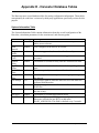
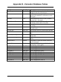
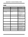
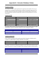
Appendix D - Harvester Database Tables
D-1
iv
Contents
Issued May-2013
OpenBSI Harvester Manual
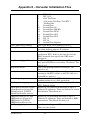
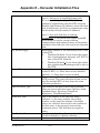
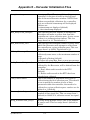
Appendix E – HARVESTER Initialization Files
E-1
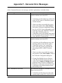
Appendix F - Harvester Error Messages
F-1
Addendum – Using the Data File Conversion Utility
Issued May-2013
Contents
v
This page is intentionally left blank
Introduction - What is the Harvester?
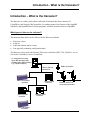
Introduction – What is the Harvester?
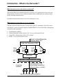
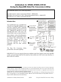
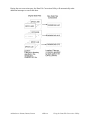
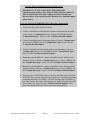
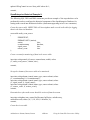
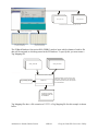
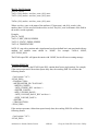
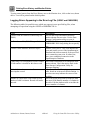
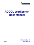
The Harvester is a utility which allows collection of historical data from a network of
ControlWave and Network 3000 controllers. It combines many of the features of the OpenBSI
Scheduler and OpenBSI Data Collector programs, available in earlier releases of OpenBSI.
What types of data can be collected?
This historical data which can be collected by the Harvester includes:
•
•
•
•
Data array values
Archives
Audit data (alarms and/or events)
Lists (typically containing configuration data)
The Harvester can be used with Network 3000 series controllers (DPC 3330, TeleFlow, etc.) as
well as the ControlWave series of controllers.
PC workstation running
Open BSI and Harvester
software (plus HMI software
e.g. OpenEnterprise)
Cable or dial-up
connections
ControlWave
controller
Network 3000
controller
Network 3000
controller
Radio connection
Network 3000 Flow
computers/correctors
Network 3000
controller
ControlWave
controller
1
OpenBSI Harvester
Introduction - What is the Harvester?
What determines how often data is collected?
Data can be collected at scheduled intervals e.g. hourly, or at a specified set of up to ten times
during the day, or based on a pre-defined collection scheme which takes into account various
factors affecting communications.
OpenBSI communications must be active for collections to occur.
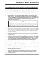
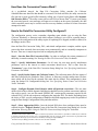
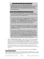
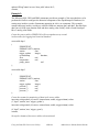
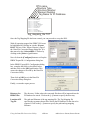
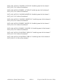
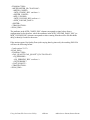
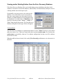
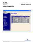
What happens to the data once it is collected?
The data collected by the Harvester is stored in files at the PC workstation. These files can be
converted to a variety of formats using the OpenBSI Data File Conversion Utility, making them
accessible to other programs:
•
•
•
•
OpenEnterprise database
Comma Separated Variable format (CSV) - for use in Microsoft® Excel
Coastal Flow Measurement's Flow-Cal™ package
ODBC - for use in Microsoft® Access
Export to OpenEnterprise,
Access, Excel, etc.
Data File Conversion Utility
Array
data
files
Archive
data
files
Audit
data
files
List
data
files
Harvester
PC
Open BSI Communications Layer
Controller
Network
Communication Link
(direct cable connection,
dial-up modem, or radio)
Inputs from field instrumentation
OpenBSI Harvester
2
Introduction - What is the Harvester?
Overview of Steps Which Must be Completed to Successfully Use the Harvester
1.
The OpenBSI Network Edition, and the Harvester kit must be installed on your PC
workstation. In addition, if this is a new system, you will need the ControlWave Designer
kit, and/or the ACCOL Workbench kit, to create a control strategy which will execute in
the controller.
2.
Create structures in your control strategy which will hold the data you want to collect
with the Harvester. These structures can include lists, arrays, archives, or audit trail. You
may find it advantageous to use the same signal names, list numbers, array numbers, and
archive numbers in each controller you configure, since this can simplify your
configuration activities later on.
NOTE:
We strongly recommend you consider using Archives instead of Arrays, because
Archives are more versatile. Archives include sequence numbers and timestamps
which simplify data management, and make data collection more efficient.
3.
Create necessary configuration signals in each control strategy. These are used for modem
control, and to set various modes of operation for the controller, when it is used with the
Harvester. Again, you may find it advantageous to use the same configuration signal
names in each controller.
4.
Download the completed and compiled control strategy files (ACCOL or ControlWave)
into each controller.
5.
Configure your controller network. Before attempting to use the Harvester, you must have
an existing network of controllers to communicate with. These controllers must exist in
your NETDEF database. Verify that communications between the PC and the controller
network are functioning properly before trying to configure and use the Harvester.
6.
Start the Harvester software, and sign on.
7.
If you used lists with the same list numbers and signal names, you can configure common
lists at this point, otherwise, skip this step.
8.
Add new node(s), and configure the node(s) using the Node Configuration pages, and the
Collection Configuration dialog box.
9.
Edit the system information to specify the locations where Harvester files should be
output, and if you are using the scan interval for your on-time method, specify its
associated parameters.
3
OpenBSI Harvester
Introduction - What is the Harvester?
10.
Examine the status of your collections in the monitor window.
11.
Configure the OpenBSI Data File Conversion Utility to set up export of the Harvester
data files to formats which may be exported to OpenEnterprise or various third-party
packages.
OpenBSI Harvester
4
Installing the Software
Installing the Software
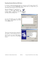
The Harvester software is included on the OpenBSI CD-ROM.
To install it, choose “Install OpenBSI” from the choices provided in the CD browser, and then
select “Harvester”. If it isn’t already installed, you should also select “Network Edition”.
Continue with the installation by following the directions onscreen. For more information on the
installation process, and on other software packages, see Chapter 2 of the OpenBSI Utilities
Manual (document# D5081).
5
OpenBSI Harvester
Configuring Your Controller
Configuring Your Controller to Work with the
Harvester
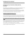
Before attempting to use the OpenBSI Harvester, your controller network must already be 'up and
running', and collecting data from field instrumentation. Instructions for setting up each
controller are included in the hardware manual accompanying the device.
The node name for each and every controller must exist in the Network Definition (NETDEF)
files. During later stages of configuration, you will need to know the node name, local address,
and expanded node addressing group number (if applicable) for each controller.
EGM 3530-10A, EGM 3530-50A TeleFlow™ Users
If you are using an EGM 3530-10A or -50A TeleFlow™ electronic gas measuring computer, it is
already pre-configured with the required signals, signal lists, Audit Trail, and archive structures;
if you need to alter the configuration, please contact our Technical Support Group for assistance.
DPC 3330, DPC 3335, RTU 3305, RTU 3310, 3530B-series, GFC 3308, ControlWave
Users
If you are using Network 3000-series DPC 3330, DPC 3335, RTU 3305, RTU 3310, 'B' or newer
3530-series units supporting ACCOL, or a GFC 3308 unit, the ACCOL load running in the unit
must be configured with certain structures. Similar structures must also be created if you are
using a ControlWave controller running one of the IEC 61131 languages.
These structures (data arrays, the EAudit Module (or AUDIT function block for ControlWave),
signal lists, and signals) are discussed, briefly, below:
OpenBSI Harvester
6
Configuring Your Controller
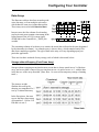
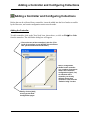
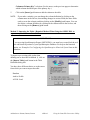
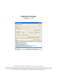
Data Arrays
The Harvester collects data from an analog readwrite data array, or from multiple such arrays
which share the same row/column dimensions.
These arrays are used to hold historical data.
In most cases, the first column of each analog
read-write array must contain a timestamp in the
Julian format of the ACCOL system signal
#TIME.000 or the ControlWave _TIME_000
variable.
The remaining columns of each array row contain the actual data collected at the time designated
by the timestamp in column 1. An example array is shown, above, which contains hourly flow
data from a natural gas pipeline. The type of data in the array will vary depending upon your
particular application.
There are four basic methods of array storage, each of which is discussed, below:
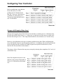
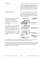
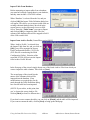
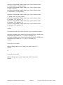
Storage without Wrapping (Push Down Array)
Storage without wrapping means that the most recent data is always stored in row 2 of the data
array; and as new data is entered, the previous data in row n is moved to row n+1, with the data
in the last row of the array discarded. (Note: Row 1 is reserved for temporary storage of running
totals.)
The pictures at right
illustrate this concept by
showing two snapshots of a 5
row by 4 column data array.
In the first picture, the most
recent data has a time stamp
of September 2, 1994 at 2:10
PM and is in row 2.
7
OpenBSI Harvester
Configuring Your Controller
In the second picture, new data has
been collected, at 3:10 PM,
pushing the 2:10 PM data down
into row 3, the row 3 data into row
4, and the row 4 data into row 5.
The previous data that had been in
row 5 is discarded.
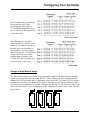
Storage with Wrapping (Wrap Array)
Storage with wrapping means that if the most recent data is currently in row n of the data array,
the next data will be stored in row n+1, unless row n is the last row of the array, in which case,
the next data will go to row 1. This wrap-around method is also referred to as a 'circular' array.
In this way, the oldest data is always overwritten with the newest data. When configuring this
array, data should always be stored beginning with Row 1. In addition, data must be stored in the
array at regular intervals, which are less than or equal to the specified scan interval. (Scan
intervals are discussed later in this manual.)
The pictures, below, illustrate the wrap array concept by showing three snapshots of a 5 row by 4
column data array.
In the first snapshot, the most recent
data has a time stamp of September 2,
1994 at 3:10 PM and is in the fourth
row.
OpenBSI Harvester
8
Configuring Your Controller
In the second picture, new data has
been collected, at 4:10 PM,
overwriting the oldest data (i.e.
11:10 AM data which had been in
row 5). The 12:10 PM data in row 1
is now the oldest.
In the third picture, new data is
collected again. It would be stored
in Row 6, except there isn't one, so
the array wraps-around and it is
stored in Row 1. Now the oldest
data, which was the 12:10 PM data
in row 1, has been over-written
with the most recent data, from
5:10 PM. The next collection will
overwrite Row 2, and so on.
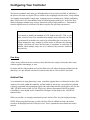
Storage in Wrap Multiple Arrays
The final method of data array storage is typically used in applications involving large amounts
of data, such as gas flow metering, using the GFC 3308 AccuRate Gas Flow Computer with its
standard ACCOL load. In this type of application, arrays in the GFC 3308 unit's ACCOL load are
configured to store data on an hourly basis, and each array has 24 rows, one for each hour in the
24 hour period corresponding to a 'gas day.' When the gas day ends, i.e. the first array is full, new
data is stored in another array, until that array is full, and then still another array is used. (See the
figure, below.)
9
OpenBSI Harvester
Configuring Your Controller
This process continues until some pre-defined number of arrays has been filled, at which time,
the process will start over again. (This is similar to the wrapping discussed earlier, except instead
of wrapping around within a single array, wrapping occurs to another array.) When configuring
these arrays in ACCOL, data should always be stored beginning with Row 1 of the first array.
When wrapping to another array, storage should also always begin with Row 1. Data must be
stored at regular intervals, which are less than or equal to the specified scan interval.
IMPORTANT
If you decide to modify the standard ACCOL load for the GFC 3308, or you
create a load of your own, remember that multiple array collection can only
be performed if each and every array to be collected has the exact same row /
column dimensions. Any attempt to collect arrays of different sizes through
multiple collection will cause the Harvester to terminate its collection. In
addition, when multiple arrays are to be collected, they must be numbered
consecutively.
Raw Array
A Raw Array collection involves an array where the Harvester simply collects the entire array,
without regard to timestamps, or rows.
No matter which of the methods are used, the Harvester will collect the historical data from the
data arrays, at a pre-defined scan interval, and store the data in files on the PC hard disk.
Archive Files
As an alternative to using data arrays, some controllers support the use of historical archive files.
Archive files reside within the controller, and are similar to data arrays, except that each column
is directly associated with a particular signal, and each column also has a descriptive title. See the
'ARC_STORE' section of the ACCOL II Reference Manual (document# D4044) for details.
ControlWave users should see the ControlWave Designer on-line help for the ‘ARCHIVE’
function block.
Wherever possible, we strongly recommend you use Archive Files for your historical storage.
NOTE: When using the Harvester to collect Archive Files in a BSAP network, the archive
records to be displayed must be 220 bytes or less. This is explained in more detail later in this
manual.
OpenBSI Harvester
10
Configuring Your Controller
EAudit Module, Audit Function Block
ACCOL users must configure the Extended Audit Trail Module (EAudit). 1 This module is used
to record alarm and event conditions, and is discussed in detail in the 'Audit Trail /EAudit'
section of the ACCOL II Reference Manual (document# D4044.) Similarly, ControlWave users
must configure the AUDIT function block. See the ControlWave Designer on-line help in
ControlWave Designer for details.
The alarm/event data is collected by the Harvester, and stored in files on the PC hard disk.
Signal Lists, Configuration Signal List
The Harvester can collect signal lists. One of these lists may be the Configuration Signal List
which contains any configuration parameters related to your particular application. The
configuration list generally contains information which does not change often, because it is
normally collected only on system startup, if a change occurs, or if the operator explicitly
requests that it be collected. In a natural gas pipeline application, for example, this list might
contain signals whose values represent pipe diameters, or orifice types.
NOTE: Signal lists collected via the Harvester cannot have more than 1000 signals.
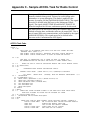
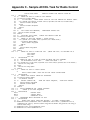
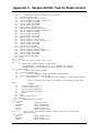
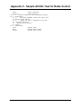
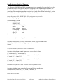
Radio Turn ON Time Logic
If you are using radios as your communication link, your program must include user-defined
logic to turn ON its radio, at a pre-determined time, so as to be ready for data collection from the
Harvester. This pre-determined time is calculated based on the node's local address, its expanded
node addressing group number, and various parameters defined in the Harvester. Appendix C of
this manual includes a sample ACCOL task which may be used to turn on a Network 3000
controller's radio at a scheduled time. For information on the turn on logic for the Harvester
program, see the box, below:
1
Protected mode firmware (PLS00/PLX00 or newer) currently only supports use of the EAudit Module. 186-based
units (except for the 3308) with AL (or newer firmware) or 386EX Real Mode units with RMS02 (or newer
firmware) can be used with either the Audit Module, or the EAudit Module.
11
OpenBSI Harvester
Configuring Your Controller
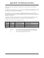
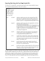
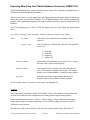
Calculation of N ode Turn ON Time, Actual Collection Time
Turn ON Time = Start Time Offset + ([Local Address - 1]* Poll Time Per Node)+
(Expanded Node Addressing Group No.)* (Poll Time Per Group)
Actual Start of Collection = Turn ON Time + Turn on Delay
So, for example, if:
Start Time Offset = 1 second
Poll Time Per Node = 20 seconds
Poll Time Per Group = 5 seconds
Turn on Delay = 5 seconds
Then, the controller with the group # and local address # shown, will turn ON at
the time within the scan interval shown:
Group # Local Address #
0
0
0
1
1
1
2
2
2
1
2
3
1
2
3
1
2
3
Turn ON time Actual Start of
Collection
1 second
6 seconds
21 seconds
26 seconds
41 seconds
46 seconds
6 seconds
11 seconds
26 seconds
31 seconds
46 seconds
51 seconds
11 seconds
16 seconds
31 seconds
36 seconds
51 seconds
56 seconds
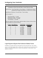
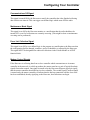
Logical Signals to Regulate Data Collection & Modem Control
In addition to the signals collected via the signal lists, and turn ON time logic, each program
requires certain logical signals which are either used to notify the Harvester to perform a certain
function, or are used by the Harvester, to indicate it has performed a certain function. These
signals are as follows:
OpenBSI Harvester
12
Configuring Your Controller
Communications Off Signal
This signal is turned ON by the Harvester to notify the controller that it has finished collecting
data for this scan interval. This can trigger user-defined logic which turns OFF the radio.
Maintenance Mode Signal
This signal is set ON by the Harvester monitor as a notification that the radio should not be
turned OFF, even if no collections are currently occurring. (This might be done so maintenance
or testing can be performed.)
Force List Collection Signal
This signal is set ON by user-defined logic in the program as a notification to the Harvester that
the configuration list has changed, somehow, and so it should be re-collected by the Harvester.
This signal MUST be designated for audit trail collection via the EAudit Module or AUDIT
function block.
Modem Control Signals
If the Harvester is collecting data from a slave controller which communicates to its master
controller in the network via a dial-up modem, the master must have a pair of logical (boolean)
signals for modem control. One signal is turned on by the Harvester (Request signal) to signify
that the master controller should dial-up its slave controller. The second signal (Confirm signal)
is turned on by the master controller to indicate that the dial-up connection with the slave node
has been established, thereby signifying to the Harvester, that collections can begin.
13
OpenBSI Harvester
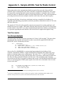
Starting the Harvester
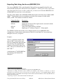
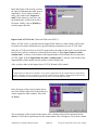
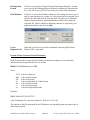
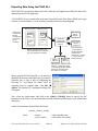
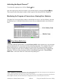
Starting the Harvester
In order to start the Harvester, communications with the controller network must already be
active, via NetView. To start the Harvester, click as follows: StartProgramsOpenBSI
Tools Collection ProgramsHarvester
IMPORTANT: If this is the very first time the Harvester has been started
on this particular computer, you will be prompted to register the software.
Otherwise, the software can only be used for a maximum of 60 days. For
more information on the registration process, see Chapter 2 of the OpenBSI
Utilities Manual (document# D5081).
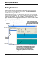
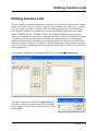
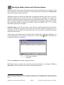
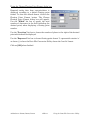
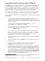
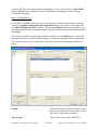
The Harvester Main Page will appear, as shown below:
Menu bar
Timestamp associated with most
recent collection
These sections of the screen
allow you to monitor information
about the status of the currently
configured collections.
Tool bar
Tree of
configured
controllers
Status bar
This window pane can display either a list of the active
nodes (controllers for which collections are occurring
right now) or a list of nodes which are in Maintenance
Mode, or a list of nodes which are experiencing
communication problems, or any current Harvester
debugging messges. You can select which items are
displayed either from icons in the tool bar or from the
“View” menu bar selection.
OpenBSI Harvester
14
Defining Common Lists
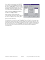
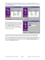
Defining Common Lists
If you are running an identical application load/project in more than one controller, that contains
signals you want to collect, you can use Common Lists to simplify your collections. A common
list is just a group of signals you want to collect, in which the signals share the same name in
more than one controller. For example, if you have ten controllers, and each one has signals
named CURRENT.FLOW, CURRENT.TEMP, and CURRENT.PRESUR that you want to
collect, you could define a Common List containing these three signals. The advantage is that the
Common List is defined in only one place (the Harvester program itself); so as long as those
individual signals already exist in the your running application, you don’t need to modify your
application to add or change the Common List. Another advantage of using common lists is that
you save on certain communications overhead, because signal names do not need to be collected,
just the signal values.
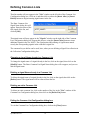
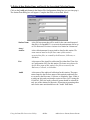
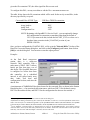
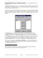
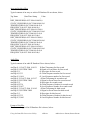
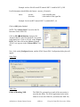
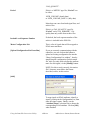
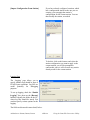
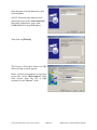
To access the Common List Configuration dialog box, click on Edit Common Lists.
To create a common list, click on the [Add List] button.
The Enter Common List Number dialog box will appear.
Enter a number which will identify the common list, then
click on [OK].
15
OpenBSI Harvester
Defining Common Lists
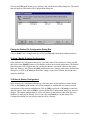
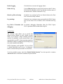
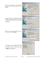
That list number will now appear in the "List" window on the left side of the Common List
Configuration dialog box. Click on it, and then click on either the [Insert After] or [Insert
Before] buttons to begin inserting signal names in the list.
The Enter Common List
Signal Name dialog box will
appear. Enter the name of the
first signal of the list, and
click on [OK].
That signal name will now appear in the "Signals" window on the right side of the Common
List Configuration dialog box. Repeat this process, using the [Insert After] button to insert
additional signals in the list. NOTE: The signal names and ordering of signals must match
exactly the corresponding signals in the controller's signal list.
The common list you define can be used, later, when you are defining a Signal List collection in
the Collection Configuration dialog box.
Changing a signal Name already in a Common List
To change the signal name of a signal already in the list, click on the signal, then click on the
[Modify] button. The Enter Common List Signal Name dialog box will re-appear, and you can
edit the signal name.
Deleting a signal Name already in a Common List
To delete the signal name of a signal already in the list, click on the signal, then click on the
[Delete] button. The signal name will be removed from the list.
Deleting an entire Common List
To delete an entire common list, click on the number of the list, in the "List" window of the
Common List Configuration dialog box, then click on the [Delete List] button.
Exiting the Common List Configuration dialog box
To exit the Common List Configuration dialog box, click on the [Close] button.
OpenBSI Harvester
16
Adding a Controller and Configuring Collections
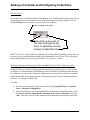
Adding a Controller and Configuring Collections
Before data can be collected from a controller, it must be added into the list of nodes accessible
by the Harvester, and certain configuration entries must be made.
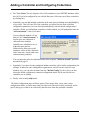
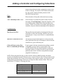
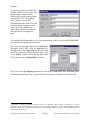
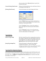
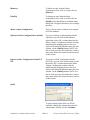
Adding the Controller
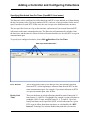
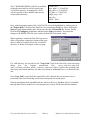
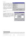
To add a controller, click on the 'New Node' icon, shown above, or click on File New Node
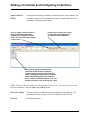
from the menu bar. The Add Nodes dialog box will appear.
First, select one of the controllers in this list. (This
list is all controllers in your NETDEF file which have
NOT yet been defined in the Harvester.)
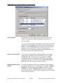
Next, if configuration
details for the controller
(e.g. numbers of structures
used in the collections,
configuration signals, etc.)
are identical with a
controller you already
defined, choose that
controller’s name from the
“Default Config” list box.
Finally, click on [Add]
to bring up the Node
Configuration pages.
17
OpenBSI Harvester
Adding a Controller and Configuring Collections
•
The "New Nodes" list box, displays a list of all controllers in your NETDEF database which
have NOT yet been configured for use with the Harvester. Select any one of these controllers
by clicking on it.
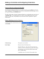
•
Optionally, you can add multiple controllers at the same time by holding down the [Ctrl] key
as you select. This will cause all of the controllers you add to have the same collection
configuration parameters (you can alter them individually, after the initial configuration is
complete.) When you add multiple controllers via this method, you will prompted to enter an
"Auto Increment" value (in seconds).
If your collection method is 'Time
Interval', the "Auto Increment" is
used to space out collections if
collections from multiple
controllers are scheduled to occur
within the same interval.
(Otherwise the Harvester would
attempt to collect all the collections
at the same time, which could cause
communication problems.)
You can adjust the offset for individual nodes, later using the "Offset in seconds" parameter
described on page 23.
•
Optionally, if you have already configured another controller with a similar configuration (for
example, it shares the same configuration signal names, and will use the same list, array
numbers, etc.) you can select its name from the "Default Config" list box. Once you have
selected a default configuration, common configuration details will be used for the new
controller you are adding.
•
Finally, click on the [Add] button.
The Node Configuration pages will now appear. These pages allow you to enter various
configuration details, to choose how often your Harvester collections will be performed, and to
specify the type(s) of data to be collected by the Harvester from this particular controller.
OpenBSI Harvester
18
Adding a Controller and Configuring Collections
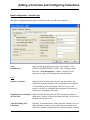
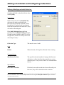
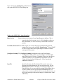
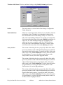
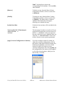
Node Configuration - General Page
The Node Configuration pages appear immediately after you add a new controller.
Node
Identification
Enter a textual description of the node. For example, 'OAK
STREET COMPRESSOR STATION'. This will appear in the
Harvester "Node Information" window. Only the first 64
characters you enter will be displayed as the description.
Flags
Disable Collections
When checked, the Harvester will NOT attempt to make any
collections from this controller. This would typically be checked
if a controller has been temporarily taken out of service for
repairs, or if there are communication problems which must be
fixed prior to attempting collections.
Skip Historical Collections
on First Pass
When checked, the Harvester will NOT attempt to perform an
initial array / archive collection on startup. Instead, it will wait for
the next calculated interval.
Turn Off Polling after
Collections
Normally, if communications with a particular controller are via a
dial-up modem or radio, as soon as the Harvester completes its
collections, polling would be turned off, and the modem would be
19
OpenBSI Harvester
Adding a Controller and Configuring Collections
hung up, because there is no reason to continue requesting data. If
this box is NOT checked, however, polling will continue, even
after a collection has been completed. This can be useful if the
controller has a direct cable connection (i.e. it is always
connected.)
Write to Station File
When checked, will automatically update the station file used by
the OpenBSI Data File Conversion Utility. If no station file exists,
one will be created. NOTE: If there are multiple list, arrays, etc.
being collected from this controller, only the first one will be used
to update the station file.
Communications Signals
Communications Off
Signal
This signal is turned ON by the Harvester to notify the controller
that it has finished collecting data for this scan interval. This can
trigger user-defined logic which turns OFF the radio.
Maintenance Mode Signal
This signal is set ON by the Harvester as a notification that the
radio should not be turned OFF, even if no collections are
currently occurring. (This might be done while maintenance or
testing is being performed.)
Force List Collection
Signal
This signal is set ON by user-defined logic in the program as a
notification to the Harvester that the configuration list has
changed, somehow, and so it should be recollected by the
Harvester. This signal MUST be designated for audit trail
collection via the EAudit Module or AUDIT function block.
ControlWave Security
Username
RESERVED FOR FUTURE USE.
Password
RESERVED FOR FUTURE USE.
Modem Control
If the Harvester is collecting data from a slave controller which communicates to its master
controller in the network via a dial-up modem, the master must have a pair of logical (boolean)
signals for modem control.
The Harvester will turn on the request signal, which should be used as a notification to execute
user-defined logic in the master for dialing up the slave node. When this is successfully done, the
user-defined logic should set the confirm signal to ON, as a notification to the Harvester that
collections from the slave node can proceed. The Harvester will check the confirm signal at a
OpenBSI Harvester
20
Adding a Controller and Configuring Collections
user-specified interval (see "Confirm Wait" and "Retries", below).
Request Signal The Harvester turns on the "Request Signal" in the Master node, to activate
user-defined logic in the control strategy file, that will initiate a dial-up
operation to the Slave node.
Confirm
Signal
User-defined logic in the control strategy file must turn this signal on to notify
the Harvester that the Slave node has been successfully dialed, and collections
can commence.
Retries
After setting the "Request Signal", this is the number of times the Harvester
will check to see that the "Confirm Signal" has been turned ON.
Confirm Wait
After setting the "Request Signal", this is the length of time (in seconds) the
Harvester will wait before checking to see that the "Confirm Signal" has
been turned ON. This same period applies to all "Retries" as well.
21
OpenBSI Harvester
Adding a Controller and Configuring Collections
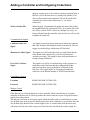
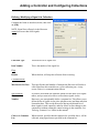
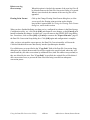
Node Configuration - Scheduling Page
NOTE: If you are using Distributed User On-Times (different from ‘User On-Times’ shown
below) skip the ‘Scheduling’ page. Distributed User On-Times is discussed later in this manual
in the ‘Specifying Distributed User On-Times’ section.
On Time Method
Only one On Time Method per controller may be used. There are three possible choices:
Scan Interval (Address
Calculations)
When this is chosen, the Harvester attempts to
communicate with a particular node based on its location
in the network, as determined by an address calculation.
Time Interval
When this is chosen, the Harvester attempts to
communicate with a particular node every time a
particular period of time has expired, for example, every
hour. See "Timer Interval Settings" below.
User On-Times
When this is chosen, the Harvester attempts to
communicate with a particular node at up to ten specified
times during the day. See the "User On-Times" section,
below.
OpenBSI Harvester
22
Adding a Controller and Configuring Collections
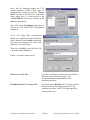
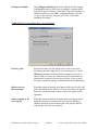
Start Historical Collections from
this Date:
If you have several days of pushdown array or archive
data stored in the controller, this allows you to specify
the first date from this historical data from which you
want the collections to begin. Any stored data for dates
earlier than this will not be collected. (This applies only
to Archive and pushdown arrays.)
First, check this box
Now click on any part of
the date and type a new
date, or optionally use the
arrows to adjust the date.
Optionally specify a different
hour than midnight here.
To set the date, check the box next to the date, then
select one of the date fields, and either enter new
numbers for the date, or use the up-down controls on the
right to adjust the date as desired.
If you want to specify that this historical data that you
collect doesn’t start at the default of midnight (0) you
can specify a different hour here (in 24 hour format 023). (Requires OpenBSI 5.9 or newer)
and hour
Time Interval Settings
Interval
Together with the "Units" this defines the period of time between
collections. For example, if the "Interval" is set to 1, and "Units" is set to
'hours', then collections will occur every hour.
Units
This defines the units of the interval. The possible choices are 'minutes',
'hours' or 'days'.
Offset in seconds This specifies a period of time in seconds (measured from the beginning of
the interval) that the Harvester will wait before beginning its collection. This
is often necessary if arrays or archives are being updated in the controller
every hour, and it is necessary to wait this number of seconds for the array /
archive manipulation to be completed. If left at 0, the collection will begin at
the very start of the interval. The offset can also be used to space out
collections, if several collections from multiple controllers are scheduled to
occur within the same interval.
23
OpenBSI Harvester
Adding a Controller and Configuring Collections
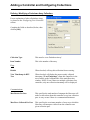
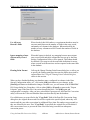
User On-Times
If User On-Times is selected as the On-Time Method, up to 10 different times during the day can
be specified as times at which the Harvester should collect data from this controller. Use the
"User On-Times" boxes, shown, to specify a time for collection.
First, check this box
Now click on any part of
the time and type a new
time, or optionally use the
arrows to adjust the time.
NOTE: If you have a large number of controllers, and do not want to manually enter on times for
each one, you can use an alternate method called Distributed User On-Times. This is discussed
later in this manual in the ‘Specifying Distributed User On-Times’ section.
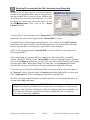
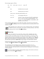
Reducing Communication Message Traffic (OpenBSI 5.8 Service Pack 1 and newer only):
By default, Harvester collects column header information each collection pass. To prevent this
re-collection of column header data and thereby reduce the number of communication messages
per collection, you can use the Advanced Configuration tool to turn off re-collection of column
header information. This option can reduce communication costs if your communication link is
expensive, for example a satellite link.
To do this:
1.
First start the Advanced Configuration tool by clicking OpenBSI Tools > Common
Tools > Advanced Configuration.
2. Then on the Harvester tab of the OpenBSI INI Configuration Settings dialog box, check
the “Do Not collect Column Header Information on Archive Collections” and click
“OK”. Harvester will not collect column header information on subsequent collections.
OpenBSI Harvester
24
Adding a Controller and Configuring Collections
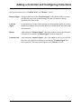
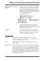
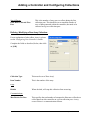
Node Configuration - Collections Page
The Collections page lists all currently configured collections for this controller, and also allows
you to configure additional collections
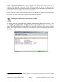
Adding a new Collection for this Controller
To add a collection, click on the [Add] button, then configure the collection in the Collection
Configuration dialog box. (See 'Using the Collection Configuration Dialog Box').
Modifying an existing Collection
To modify an existing collection, click on the line for that collection in the list of collections
window, then click on the [Modify] button to call up the Collection Configuration dialog box.
(See 'Using the Collection Configuration Dialog Box').
Deleting an existing collection
To delete an existing collection, click on the line for that collection in the list of collections
window, then click on the [Delete] button.
25
OpenBSI Harvester
Adding a Controller and Configuring Collections
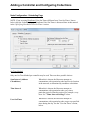
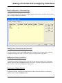
Using the Collection Configuration Dialog Box
The Collection Configuration dialog box is accessible by clicking on the [Add] button from the
Node Configuration - Collections page. If you select an existing collection on that page, you can
call it up by clicking on the [Modify] button.
The fields visible in the Collection Configuration dialog box vary depending upon your choice of
"Collection Type". The available choices are: Archive, Audit, Pushdown Array, Raw Array,
Signal List, Wrap Array, Wrap Multiple Array. Each choice will be explained in a separate
section, below.
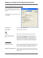
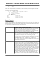
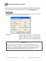
Defining / Modifying an Archive Collection:
Complete the fields as described, below, then
click on [OK]:
Collection Type
This must be set to 'Archive'.
Item Number
Enter the Archive File Number here.
Network 3000 users: The Archive File must have been
defined in ACCOL Workbench. The Archive File Number
must match the value on the ARCHIVE terminal of the
ARC_STORE module.
ControlWave users: The Archive File must have been
OpenBSI Harvester
26
Adding a Controller and Configuring Collections
defined using either the Flash Configuration Utility or the
Archive web page. The Archive File Number must match
the value on the iiArchiveNumber parameter in the
ARCHIVE function block.
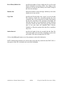
Flags
Disable
When checked, will stop this collection from occurring.
View TimeStamp in RTU Tree
When checked, will display the most recently collected
timestamp ("Last Timestamp") from this controller, in the
tree of nodes on the left hand side of the main Harvester
window. NOTE: Even if there are multiple collections for a
controller, only one collection timestamp will be displayed.
Communications
Max Retries Per Pass
This specifies the total number of attempts the Harvester
will make to collect data from this controller on a given
collection pass. A retry occurs if there is a communication
timeout.
Max Rows Collected Per Pass
This specifies the maximum number of Archive Records
(rows) which the Harvester will attempt to collect from the
controller on a given collection pass.
Collect all history using ‘Max
Rows’ as maximum per message
If your system is having communication problems, outside
of OpenBSI, you may want to use this option. This
specifies that the Harvester should attempt to collect the
maximum number of Archive Records (as specified by the
parameter above) but it will do it using shorter messages.
(OpenBSI 5.4 and newer.)
NOTE: When using the Harvester to collect Archive Files in a BSAP network, the archive
records to be displayed must be 220 bytes or less. A total of 4 bytes of the 220 are already used to
display the timestamp, plus 2 bytes are used for the local sequence number, and 2 bytes are used
for the global sequence number. This leaves 212 bytes for other columns of data. This could
include up to 53 columns of floating point data.
Type of Data
Timestamp
Local Sequence Number
Global Sequence Number
Analog Floating Point value
Logical / BOOL value
27
Number of bytes required
4
2
2
4
1
OpenBSI Harvester
Adding a Controller and Configuring Collections
Defining / Modifying an Audit Collection:
Complete the fields as described, below, then
click on [OK]:
Usage Notes:
If Harvester users select a [Demand Coll]
collection, all audit records which the
Harvester has not already collected, will be
brought back. If audit records have already
been collected and still exist at the RTU, they
will not be collected again.
If the [Init Collection] button has been
pressed, prior to a [Demand Coll] collection,
all audit records available at the RTU will be
brought back, whether or not they have been
collected previously. 1
Collection Type
This must be set to 'Audit'.
Flags
Disable
When checked, will stop this collection from occurring.
Communications
Max Retries Per Pass
This specifies the total number of attempts the Harvester
will make to collect data from this controller on a given
collection pass. A retry occurs if there is a communication
timeout.
Special Parms
Reset after Collection
If checked, once audit records have been collected by the
Harvester, they will be deleted from the controller.
1
Prior to OpenBSI 5.6 Service Pack 1, Harvester would collect all available audit records, whether or not they had
been collected earlier, unless the audit buffer had been reset, using the “Reset after Collection” option, to delete
records already collected.
OpenBSI Harvester
28
Adding a Controller and Configuring Collections
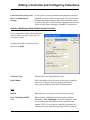
Defining / Modifying a Signal List Collection:
Complete the fields as described, below, then click
on [OK]:
NOTE: Signal lists collected via the Harvester
cannot have more than 1000 signals.
Collection Type
This must be set to 'Signal List'.
Item Number
This is the number of the signal list.
Flags
Disable
When checked, will stop this collection from occurring.
Communications
Max Retries Per Pass
This specifies the total number of attempts the Harvester will make to
collect data from this controller on a given collection pass. A retry
occurs if there is a communication timeout.
Special Parms
Common List
Number
If you have more than one controller which uses the same set of signal
names, and you want to be able to collect those signals via the
Harvester, you can optionally define a common list. This allows you to
define the list of signals in one place (the Harvester) and then enter that
list number here. This avoids the need of having a dedicated list of
those signals in each controller, and also allows on-line changes to the
common list without editing the control strategy in the controller. See
'Defining Common Lists' earlier in this manual.
Collect via Common
List
When selected, specifies that the common list, specified above, will be
collected, using signal names specified in the common list.
29
OpenBSI Harvester
Adding a Controller and Configuring Collections
Defining / Modifying a Pushdown Array Collection:
For an explanation of what a Pushdown Array
is, please see the 'Configuring Your Controller'
section.
Complete the fields as described, below, then
click on [OK]:
Collection Type
This must be set to 'Pushdown Array'.
Item Number
This is the number of the array.
Flags
Disable
When checked, will stop this collection from occurring.
View TimeStamp in RTU
Tree
When checked, will display the most recently collected
timestamp ("Last Timestamp") from this controller, in the
tree of nodes on the left hand side of the main Harvester
window. NOTE: Even if there are multiple collections for a
controller, only one collection timestamp will be displayed.
Communications
Max Retries Per Pass
This specifies the total number of attempts the Harvester will
make to collect data from this controller on a given collection
pass. A retry occurs if there is a communication timeout.
Max Rows Collected Per Pass
This specifies the maximum number of array rows which the
Harvester will attempt to collect from the controller on a
given collection pass.
OpenBSI Harvester
30
Adding a Controller and Configuring Collections
Special Parms
Push Rows Collected First
Pass
This is the number of array rows to collect during the first
collection pass. This should be set to match the number of
rows of data generated within the controller, that need to be
collected on a given collection pass.
Defining / Modifying a Raw Array Collection:
For an explanation of what a Raw Array is, please
see the 'Configuring Your Controller' section.
Complete the fields as described, below, then click
on [OK]:
Collection Type
This must be set to 'Raw Array'.
Item Number
This is the number of the array.
Flags
Disable
When checked, will stop this collection from occurring.
Communications
Max Retries Per Pass
This specifies the total number of attempts the Harvester will make to
collect data from this controller on a given collection pass. A retry
occurs if there is a communication timeout.
31
OpenBSI Harvester
Adding a Controller and Configuring Collections
Defining / Modifying a Wrap Array Collection:
For an explanation of what a Wrap Array is,
please see the 'Configuring Your Controller'
section.
Complete the fields as described, below, then
click on [OK]:
Collection Type
This must be set to 'Wrap Array'.
Item Number
This is the number of the array.
Flags
Disable
When checked, will stop this collection from occurring.
View TimeStamp in RTU
Tree
When checked, will display the most recently collected
timestamp ("Last Timestamp") from this controller, in the
tree of nodes on the left hand side of the main Harvester
window. NOTE: Even if there are multiple collections for a
controller, only one collection timestamp will be displayed.
Communications
Max Retries Per Pass
This specifies the total number of attempts the Harvester will
make to collect data from this controller on a given collection
pass. A retry occurs if there is a communication timeout.
Max Rows Collected Per Pass
This specifies the maximum number of array rows which the
Harvester will attempt to collect from the controller on a given
collection pass.
OpenBSI Harvester
32
Adding a Controller and Configuring Collections
Collect all history using ‘Max
Rows’ as maximum per
message
If your system is having communication problems, outside of
OpenBSI, you may want to use this option. This specifies that
the Harvester should attempt to collect the maximum number
of Archive Records (as specified by the parameter above) but it
will do it using shorter messages. (OpenBSI 5.4 and newer.)
Defining / Modifying a Wrap Multiple Array Collection:
For an explanation of what a Wrap Multiple
Array is, please see the 'Configuring Your
Controller' section.
Complete the fields as described, below,
then click on [OK]:
Collection Type
This must be set to 'Wrap Multiple Array'.
Item Number
This is the number of the first array in the group of multiple
arrays to be collected. All arrays in the group must be
consecutively numbered from this first array number.
Flags
Disable
When checked, will stop this collection from occurring.
View TimeStamp in RTU
Tree
When checked, will display the most recently collected
timestamp ("Last Timestamp") from this controller, in the
tree of nodes on the left hand side of the main Harvester
window. NOTE: Even if there are multiple collections for a
controller, only one collection timestamp will be displayed.
33
OpenBSI Harvester
Adding a Controller and Configuring Collections
Communications
Max Retries Per Pass
This specifies the total number of attempts the Harvester will
make to collect data from this controller on a given collection
pass. A retry occurs if there is a communication timeout.
Max Rows Collected Per Pass
This specifies the maximum number of array rows which the
Harvester will attempt to collect from the controller on a given
collection pass.
Special Parms
Number of Multiple Arrays
OpenBSI Harvester
This is the total number of arrays to be collected.
34
Adding a Controller and Configuring Collections
Specifying Distributed User On-Times (OpenBSI 5.0 and newer)
The Harvester can be configured to collect data from an RTU at a pre-defined set of times during
the day. In systems with a very large number of RTUs, however, it may be tedious for the user to
specify on-times for each RTU. In this case, the user can opt to use distributed user on-times.
The user specifies a base set of up to four on-times, and an interval (in seconds) between RTU
collections on the same communication port. The Harvester will automatically calculate, from
the base time, and the interval, offsets at which collections should occur for each RTU on a given
communication port.
To specify user configured on-times, choose Edit Distribute User On-Times
Enter up to 4 start times here
RTU Interval
This is the period of time (in seconds) to wait, after starting collection
from one RTU, before beginning a collection from the next RTU on this
same communication port. For example, if you want collections to RTUs
on a port one minute apart, enter 60 here.
Hourly Start
Times
These are the hours in which collections should be started, entered in 24
hour format (1=1AM, 24=12 midnight) For example, to start collections at
midnight, 6AM, 12 noon, and 6PM, enter 24, 6, 12, and 18. Up to four
hourly start times can be specified. NOTE: Actual collections for a given
RTU occur at offsets from these start times, as calculated by the “RTU
Interval”. Entering 0 for an hour disables that particular user on-time.
35
OpenBSI Harvester
Adding a Controller and Configuring Collections
[Apply Times to
RTUs]
This loads the Harvester Database collection schedule, and calculates, for
each RTU on a given PC communication port, at which offsets from the
start times, collections should occur.
Click on [Apply Times to RTUs] to
bring in the existing Harvester
database and calculate collection
times, which the Harvester displays
on the screen.
Finally, click on [Save New Times]
to store the newly defined times
for collection in the database.
Each column displays collections the
Harvester makes through a particular
communication port on the PC. Each RTU
name is displayed, followed by a calculated
offset from the beginning of the start time
hour, at which a collection should occur. The
offsets are based on the “RTU Interval” value.
NOTE: The new collection offsets are only displayed on the screen. They must be stored in the
Harvester database, using the [Save New Times] button.
[Save New Times]
This stores the newly defined collection schedule in the database. You
must do this before exiting, or the new schedule will not be used.
[Cancel]
Exits the dialog box.
OpenBSI Harvester
36
Adding a Controller and Configuring Collections
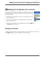
Modifying the Configuration for a Controller
Once you have added a controller, and configured collections for it in the Node
Configuration pages, you can recall those pages to modify the configuration by
three different methods:
•
Double-click on the controller's icon in the tree on the left hand side of the
Harvester main page or
•
Click once on the controller's icon (to highlight it) then click on the Edit
Node icon, shown above or
•
Click once on the controller's icon (to highlight it) then click on Edit Node
Configuration from the menu bar.
Deleting a Controller
To delete a controller from the list of configured nodes, click on the controller's icon, then click
on File Delete Node. You will be prompted to confirm the deletion.
37
OpenBSI Harvester
Defining System Information
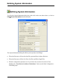
Defining System Information
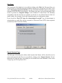
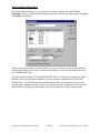
To call up the System Information dialog box, either click on the icon, shown above, or click on
Edit System Information from the menu bar.
The System Information dialog box allows you to specify several things:
Where the Harvester will store the data files generated from its data collections.
Where the Harvester will look for Write List Files and Write Signal Files.
What the configuration parameters are if you choose the scan interval as the On Time
Method. (See "Scan Interval (Address Calculations)" choice on the Node Configuration Scheduling page.)
OpenBSI Harvester
38
Defining System Information
Scan Interval Method Configuration:
Scan Interval
This value defines the period of time (in
seconds) over which the Harvester will
attempt to collect data from each and every
node in the network. Typically, this would be
set to 3,600 seconds to indicate that
collections occur hourly, however the value
can range from 600 to 172,800 seconds, and
should be set large enough to accommodate
collection of data from all of the nodes under
normal operating conditions. The initial scan
interval is measured from 00:00:00 (midnight)
of the current day, therefore it is
recommended that the scan interval be chosen
so as to divide a 24 hour period into equal
parts (without remaining time left over).
Start Time Offset
This value defines the offset into the scan
interval, at which the polling should start. If,
for example, the scan interval is 3,600
seconds (1 hour), and the start time offset is
60 seconds, no polling will start until after the
first minute of the hour has expired. The Start
time offset can range from 0 to 3600 seconds.
Poll Time per Node
This value defines the amount of time
required to poll a single node for data, under
normal operating conditions.
Poll Time per Group
This value defines the amount of time from
the start time for polling nodes from one
expanded addressing group, before the
Harvester will attempt to start polling nodes
from the next expanded node addressing
group. See the ACCOL II Reference Manual
(document# D4044) for details on expanded
node addressing. This value can range from 0
to 3600 seconds.
Turn On Delay
This is a delay (in seconds) which is added to
the calculated 'ON' time, which must expire
before the actual collection begins. This value
can range from 0 to 3600 seconds. See the
calculation on page 13 for details.
39
OpenBSI Harvester
Defining System Information
Harvester Directories:
Raw File Storage Directory
This entry defines the DOS drive and
directory (file path) where array, archive,
audit trail, and list files will be stored. You
can type the path in directly, or use the
[Browse] button to locate it.
Write File Directory
This entry defines the DOS drive and
directory (file path) where the Harvester will
look for Write List (*.WLS) files and Write
Signal (*.WSG) files. (These files are
discussed, in detail, in Appendix A.) You can
type the path in directly, or use the [Browse]
button to locate it.
Stagger Mode:
Number of Active Nodes forcing Stagger
Mode
The OpenBSI Harvester will automatically
enter stagger mode if the number of nodes,
which the Harvester is currently attempting to
communicate with, is greater than or equal to
"Number of Active Nodes forcing Stagger
Mode".
Number of Nodes to skip in Stagger Mode
If, the number of nodes the Harvester is
actively trying to collect data from exceeds a
user-defined number, it is said to be in an
’over-run’ condition, and so will enter stagger
mode. In stagger mode, the Harvester will
only attempt to collect the full amount of new
data from a portion of all of the nodes during
any scan interval. For each node which the
Harvester collects from it will skip a full
collection from "Number of Nodes to skip
in Stagger Mode" nodes. For example, if
"Number of Nodes to skip in Stagger
Mode" is set to 5, the Harvester will collect
the full amount of data from one node, skip
full collections from the next 5 nodes, then
collect the full amount of data from another
node, then skip another 5 nodes, etc. In other
words, the full amount of data is only
collected from every 6th node. On the next
OpenBSI Harvester
40
Defining System Information
scan interval, the Harvester will collect the
full amount of data from a different set of
nodes (again, skipping 5 nodes for each node
collected) and so on. This effectively staggers
collections over "Number of Nodes to skip
in Stagger Mode" + 1 scan intervals. When,
and if, the Harvester’catches up’ and has
collected all data not collected on previous
passes, it will return to its normal collection
method, as defined by the scan interval.
Setting "Number of Nodes to skip in
Stagger Mode" to 0 effectively prevents the
use of stagger mode.
Dial:
Number of Dial Retries on a busy line
If when attempting to dial, a busy signal is
encountered, this is the number of dial retry
attempts which will be made.
Time in seconds to wait between Dial Retries
This is the length of time (in seconds)
between dial retry attempts.
DIALING APPLICATION NOTE
If you have multiple controllers multi-dropped on the same dial-up line, once
OpenBSI has successfully connected to the first node, you can configure it to also
continue to poll, in sequence, all other nodes on that same dial-up line. To do this, you
must set the SpecialDial parameter in the BSBSAP.INI initialization file to 1.
41
OpenBSI Harvester
Monitoring the Status of Your Collections
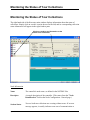
Monitoring the Status of Your Collections
The right hand side of the Harvester main window displays information about the status of
collections. Simply click on a node's icon (in the tree on the left) and its corresponding collection
status information will appear in the right window pane.
Click on a node to see information on the
status of its collections.
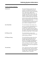
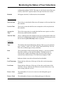
Node Information
Name
The controller's node name, as defined in the NETDEF files.
Descriptor
A textual description of the controller. (This comes from the "Node
Identification" field on the Node Configuration - General page.)
Session Status
'Success' indicates collections are occuring without errors. If an error
message appears, it usually indicates some sort of communication or
OpenBSI Harvester
42
Monitoring the Status of Your Collections
configuration problem. NOTE: This status is only for the current Harvester
session, it does NOT report the status of the previous Harvester session.
Disabled
Will appear checked, if collections have been disabled.
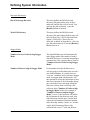
Time Information
Next On Time
This is the next time that the Harvester will attempt to collect any data from
this controller.
Last On Time
This is the last time that the Harvester attempted to collect any data from
this controller.
Average On
Time
This is the average time (in seconds) that the Harvester requires to collect
all necessary data from this controller.
Total On Time
This is a running total of the amount of time (in seconds) that the Harvester
has been in communication with this node during all collection passes since
the last time the [Init Collection] button was pressed.
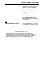
Collections
Type
This indicates the kind of data being collected. There are seven collection
types: 'Archive', 'Audit', 'List', 'Raw', 'Wrap' 'Push' and 'MWrap'. The last
four refer to different types of array collection.
Item
This is the number of the structure being collected, i.e. the array number,
the archive number, or the signal list number. If multiple arrays are
collected, this would be the number of the first array in the group of
consecutively numbered arrays. This field does not apply to Audit.
Dis.
Indicates whether or not this collection has been disabled.
Last Timestamp
During the last collection, of this type of data, this was the timestamp
collected.
Last Status
During the last collection, of this type of data, this was the status of the
collection. 'Success' indicates the collection occurred without errors. Any
other message indicates an error.
Errors - Cons.
The total number of consecutive errors received during this type of
collection.
Errors - Total
The total number of errors received during this type of collection.
43
OpenBSI Harvester
Monitoring the Status of Your Collections
Retries - Cons.
The total number of consecutive communication retries made during this
type of collection.
Retries - Total
The total number of communication retries made during this type of
collection.
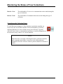
Controllers with Collection Errors
If, as the Harvester attempts to collect data from a particular controller, an
error occurs, the icon for that controller will be surrounded by an red box,
indicating that there are errors with the most recent collection. Typically,
collection errors relate to communication problems, or invalid configuration of
the structures (arrays, archive, etc.) in the controller.
NOTE:
If the Harvester is currently collecting data from a particular controller,
and a communication failure occurs prior to the collection being
completed, Harvester will store whatever partial valid data it was able to
collect.
OpenBSI Harvester
44
Monitoring the Status of Your Collections
Viewing / Hiding the Tool Bar
If desired, you can remove the Tool Bar from the screen by clicking on ViewToolbar. To
restore the Tool Bar, repeat the same command.
Viewing / Hiding the Status Bar
If desired, you can remove the Status Bar from the screen by clicking on ViewStatus bar. To
restore the Status Bar, repeat the same command.
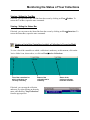
Viewing a List of the Controllers in which a Collection is Occurring Right
Now
To view a list of the controllers to which a collection is underway, at this moment, click on the
'Active Nodes' icon, shown above, or click on ViewActive Collections.
List of the controllers for
which collections are
currently underway.
Status of the
collection that is
underway.
Status of the
previous collecton
from this controller.
If desired, you can stop the collection
underway, by right clicking on the node
name, and choosing "Stop Collections"
from the pop-up menu.
45
OpenBSI Harvester
Monitoring the Status of Your Collections
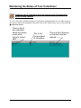
Viewing a List of Controllers which are experiencing Communication
Errors or other Failures
To view a list of the controllers which are experiencing communication errors or other errors on
one or more of their last scheduled collections, click on the 'Node Errors' icon, or click on View
Collection Errors.
This is a list of
the controllers
which are having
errors while
trying to collect
data.
OpenBSI Harvester
This is the
current status
of collections
46
This is a list of the error
on the last collection
attempt
Monitoring the Status of Your Collections
Viewing a list of Debugging Messages
The Harvester reports various debugging messages which relate to how collections are
occurring, and what errors are encountered. These messages are primarily for use by Bristol
development and support personnel, however, they may be viewed by clicking on the 'Debug
Msgs' icon, shown above, or by clicking on View Debug Messages. NOTE: Only debugging
errors related to the currently selected controller will be displayed.
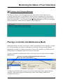
Placing a controller into Maintenance Mode
Maintenance Mode is a mode of operation in which communications with a controller (via radio,
etc.) are kept running, even when no collections are occurring. This may be useful during
maintenance or testing, or if other programs need access to the controller (e.g. DataView or an
HMI package) even though the Harvester is between collections.
To place a controller into Maintenance Mode, click on the icon for it, then click on the [Start
Maint] button.
To place a controller into Maintenance Mode, click on its
icon, then click on [Start Maint].
The Harvester will then send a message to turn ON the Maintenance Mode signal inside the
controller. (This signal triggers user defined logic in the control strategy which leaves
communications active.)
47
OpenBSI Harvester
Monitoring the Status of Your Collections
Once Maintenance Mode has been successfully activated, the icon for the controller
placed into maintenance will be displayed with a yellow “M” over it, and the controller
will be added to the list of controllers in Maintenance Mode.
Viewing the List of Controllers Currently in Maintenance Mode
To view a list of the controllers currently in Maintenance Mode, click on the 'Maint. Mode' icon,
shown above, or click on ViewMaintenance Mode.
Controllers which
are currently in
Maintenance Mode
Status of the
controller
Status of
last collection
Taking a Controller Out of Maintenance Mode
To remove a controller from Maintenance Mode, click on the icon for it, then click on the [Stop
Maint.] button.
OpenBSI Harvester
48
Monitoring the Status of Your Collections
Turning on Polling for a Particular Controller
Polling is a term referring to a request for data sent by the OpenBSI communications system to
the controller network. Normally, polling from a particular controller would only be activated
when the Harvester is ready to perform a collection, according to a predefined schedule. For
example, in a radio system, polling of a particular controller would only occur when radio
communication is scheduled to be active with that controller; at all other times, polling of that
controller would be shut off.
The [Start Poll] button allows the user to force polling at other non-scheduled times (for
example, if communications with the controller need to be tested.) To do this, click on the icon
for the controller you want to poll, and click on the [Start Poll] button. Polling will begin. You
can shut off polling by clicking on the [Stop Poll] button.
Performing an 'On Demand' Collection
If you want the Harvester to collect data
from a controller at some time other than
when it is normally scheduled to perform a
collection, you can force an 'on demand'
collection.
To do this, click on the icon for the controller from which you want to collect data, and click on
the [Demand Coll] button. The On Demand dialog box will appear.
In the "Enter maximum number of records to collect" field, enter the maximum number of
records (i.e. array rows, archive rows, signals from a list) that you want to collect, then click on
[OK]. The Harvester will immediately attempt to perform collections from that controller.
Clearing Error, Status, and Timestamp Information
using ‘Init Collection’
To clear (erase) the Error, Last Collection, and Timestamp information showing in the window
for a particular controller, click on the icon for that controller, then click on the [Init Collection]
button.
49
OpenBSI Harvester
This page is intentionally left blank
Appendix A - Writing File Data to Signals
App endix A - W riting File D ata to Sign als
The Harvester's can optionally read ASCII text files containing signal values, and write those
signal values to corresponding signals in the node. This is useful for changing the value of
configuration signals in the node.
There are two different file formats supported - Write List Files (*.WLS) and Write Signal Files
(*.WSG).
During the collection of data for a particular node, the Harvester will check to see if a WLS or
WSG file exists for that node; if it does, the values in the file will be written to the node, during
the collection pass.
Write List File Format
The Write List File must be in an ASCII text format, and must be located in the Write Files
directory, as specified in the "Write File Directory" in the Harvester's System Information
dialog box. The file base name must be the node name, as defined in the NETDEF files, and the
file extension must be "WLS".
The format of the Write List File is presented below:
n number of list definitions in this Write List File
list definition 1
list definition 2
.
.
.
list definition n
where a list definition consists of:
the number of the signal list
the starting index into the list
x number of signals being written to
value 1
value 2
.
.
value x
Values in the definition must be consecutive. They can be analog values; or for logical signals,
either ON/OFF or TRUE/FALSE.
A-1
Open BSI Harvester
Appendix A - Writing File Data to Signals
In the example shown, below, a Write List file has been created for the node called RTU3. Its
Write List File must therefore be named RTU3.WLS.
The first line of the RTU3.WLS file indicates that it contains 2 list definitions.
The first list definition applies to signal list 1 in RTU3, and will write to 2 consecutive list
entries, starting with the fifth entry in the list. It will write a value of 1.9 to the fifth entry in the
list 1, and a value of TRUE to the sixth entry in list 1.
The second list definition applies to signal list 27 in RTU3. It will write to 3 consecutive list
entries, starting with the eighth entry in the list. It will write a value of ON to the eighth entry of
list 27, a value of 1001 to the ninth entry of list 27, and a value of 45 to the tenth entry of list 27.
File Entry in RTU3.WLS Explanation
2
1
5
2
1.9
TRUE
27
8
3
ON
1001
45
number of list definitions
list definition for signal list 1
start with 5th signal in signal list 1
write values to 2 consecutive signals, i.e. signal 5 and 6 in list1
signal 5 value
signal 6 value
list definition for signal list 27
start with 8th signal in signal list 27
write values to 3 consecutive signals, i.e. signals 8, 9, and 10
signal 8 value
signal 9 value
signal 10 value
Write Signal File
A Write Signal File must be in an ASCII text format, and must be located in the Write Files
directory, as specified in the "Write File Directory" in the Harvester's System Information
dialog box. A Write Signal file must be named
node.WSG
where the file base name of node is the node name of the controller which will be written to, and
WSG is the file extension. This node name must exist in the NETDEF files. The first line of the
WSG file must be an integer specifying the number of signals in the file. Each of the remaining
lines of the file must consist of a signal name, and a signal value, separated by a space. Either
analog or logical signals may be used; string signals are not supported. If a logical signal is used,
its value must be either ON/OFF or TRUE/FALSE.
In the example shown, below, a Write Signal file has been created for the node called DPU5. Its
Write Signal file must therefore be named DPU5.WSG.
Open BSI Harvester
A-2
Appendix A - Writing File Data to Signals
3
VALVE01.OPEN.NOW TRUE
PUMP01.POWER.ON ON
SETPOINT.WATER.TEMP 32
Open BSI Harvester
A-3
This page is intentionally left blank
Appendix B - File Naming Conventions
App endix B - File N am ing Conv ention s
The data collected from controllers by the Harvester is saved in data files at the OpenBSI
Workstation.
The directory where these files are saved is specified in the "Raw File Storage Directory" field
in the Harvester's System Information dialog box.
Once the files are saved, they are typically exported to OpenEnterprise, Microsoft® Excel, or
some other third-party package, using the OpenBSI Data File Conversion Utility, described in an
addendum to this manual.
A maximum of 999 files can be saved of a given type in the Raw File Storage Directory. Once
this number is exhausted, older files will be overwritten, as new data must be saved.
The table, below, details the file naming conventions:
File Type
Archive
Array
Audit
List
File Format
Binary
Binary
ASCII
ASCII
File Naming Convention
nnnnnnnn_Cxxx.yyy
nnnnnnnn_Axxx.yyy
nnnnnnnn_Exxx.yyy
nnnnnnnn_Lxxx.yyy
Example File Name
RPC5_C001.000
NORTHWD_A001.000
FLOW3_E001.000
PARKROAD_L001.000
Where:
nnnnnnnn
xxx
yyy
= the controller's node name (as defined in the NETDEF files)
= the structure number beginning with 001 (e.g. array number)
= the file number ranging from 000 to 999
B-1
OpenBSI Harvester
This page is intentionally left blank
Appendix C - Sample ACCOL Task for Radio Control
Appendix C - Sample ACCOL Task for Radio Control
When using radios as the communication link between the Harvester and a Network 3000
controller, power consumption by the radio is normally an important consideration. Power may
be conserved by ensuring that under normal operating conditions, a controller's radio is ONLY
turned ON when it is scheduled to send/receive data from the Harvester. This is also important in
preventing interference between multiple controllers which share the same radio frequency.
The radio turn ON logic is based on a calculation involving a controller's local address, its
expanded node addressing group number, and other parameters defined both in the ACCOL load,
and in the Harvester.
The sample ACCOL task in this appendix represents one approach to creating such logic, and
should only be used as a guide. This sample task only shows the part of the ACCOL load related
to radio control; it does NOT cover other communication details such as buffers, port definitions,
etc. Questions regarding this task should be directed to Bristol's Application Support Group.
Task Description
Turn-ON Logic Highlights
This task assumes the Harvester has a scan interval of 1 hour (3,600 seconds).1 The time within
each hour that the controller will turn ON its radio is stored in the signals HOUR.MIN and
HOUR.SEC, and is calculated by the lines:
60 *
CALCULATOR
10 :IF(#NODEADR!=127)
20
NODE.TIME=((#NODEADR-1)*26)+(GROUP.ADDR*5)+60
30
HOUR.MIN=:INT(NODE.TIME/60)
40
HOUR.SEC=NODE.TIME-(60*HOUR.MIN)
where in line 20, #NODEADR is a system signal representing the local address of this
controller, and GROUP.ADDR is a signal which holds the Expanded Node Addressing group
number (as defined during system configuration). The values "26", "5", and "60" are the poll
time per node, poll time per group, and start time offset, respectively, which must be identical to
the values for those parameters defined in the Harvester. Lines 30 and 40 of the Calculator
convert the turn ON time (in seconds) to minutes and seconds. The HOUR.MIN and HOUR.SEC
values are checked against #TIME system signals, later in the task, to determine when it is time
to turn on the radio:2
160
170
180
1
:IF((#TIME.007==HOUR.SEC)&(#TIME.006==HOUR.MIN))
:IF(RADIO.HOUR.ENBL)
RADIO.HOUR.REQ=#ON
The start time of a scan interval is measured from midnight (00:00) of the current day.
2
As part of its communication activities, the Harvester regularly sends a Node Routing Table (NRT) to each
controller. This prevents a loss of time synchronization between the PC and controllers.
C-1
OpenBSI Harvester
Appendix C - Sample ACCOL Task for Radio Control
190
:ENDIF
Later, after various checking is performed, the radio is actually activated using the Turn DTR
ON feature of the Portstatus module.
30 :C
CHECK TO SEE IF REQUIRED TO BE ON
40 :IF(RADIO.ACTIVE)
50
MASTER.RADIO.MODE=5
60 :ENDIF
330 * PORTSTATUS
PORT
MASTER.PORT.
MODE
MASTER.RADIO.MODE
STATUS
MASTER.RADIO.STAT
Modes of Operation
This ACCOL task supports 5 different modes of operation. Most of the modes also include userdefined setpoints which are fed into Timer Module logic to determine how long the radio stays
ON. Each mode is summarized, briefly, in the table below:
Local Turn ON Mode
Daily Turn ON Mode
Hourly Turn ON Mode
OpenBSI Harvester
This mode is enabled by turning ON the signal
RADIO.LOCAL.ENBL. This mode allows the radio to be activated
manually by an operator using a keypad device. The signals
LOCAL.TIME.SP and LOCAL.TIMOUT.SP are used to define the
length of the ON time, and timeout periods for this mode.
This mode supports turning on the radio daily, and is enabled by
setting valid values on the DAY.HOUR, DAY.MIN and DAY.SEC
signals. These turn ON time values are checked against the
#TIME.005 (hours) #TIME.006 (minutes) and #TIME.007 (seconds)
system signals, respectively. The signals DAY.TIME.SP and
DAY.TIMOUT.SP are used to define the length of the ON time, and
timeout periods for this mode.
This mode is the normal method of communication with the Harvester,
as discussed, above, under Turn ON Logic Highlights. This mode is
enabled by turning ON the signal RADIO.HOUR.ENBL. The actual
turn ON time is defined in the signals HOUR.MIN and HOUR.SEC.
The signals HOUR.TIME.SP and HOUR.TIMOUT.SP define the
length of the ON time, and timeout periods for this mode. A daylight
hours mode option is also provided. This option is enabled by turning
ON the signal RADIO.DLIGHT.ENBL. When ON this mode limits
the Hourly Turn ON Mode to hours between the value of
RADIO.DLIGHT.STRT and RADIO.DLIGHT.END. If the time of
day in hours, as indicated on the system signal #TIME.005 is not
between those two values, Hourly Turn ON Mode will be disabled.
C-2
Appendix C - Sample ACCOL Task for Radio Control
Maintenance Mode
Radio Turn OFF Mode
Maintenance Mode allows a radio to be left ON for longer than the
normally scheduled time period. This may be useful during radio
maintenance or system debugging. This mode is enabled by the
operator, by turning ON the signal RADIO.MAINT.REQ. (This signal
must also be defined in the Harvester as the Maintenance Mode
Signal.) The signals MAINT.TIME.SP and MAINT.TIMOUT.SP
define the length of the ON time, and timeout periods for this mode.
This mode allows the Harvester to notify the controller that it has
finished collecting data, and that the radio may be turned OFF. This is
part of normal Harvester communications, and is handled by the signal
RADIO.RESET.REQ. (This signal must also be defined in the
Harvester as the Communications OFF Signal.)
ACCOL Task Code
*TASK 6
10 * C@
THIS TASK IS TO CONTROL THE RADIO VIA THE DTR SIGNAL ON THE@
NETWORK PORT (PORT C).@
THE SIGNAL "RADIO.ACTIVE." CONTROLS THE PORT STATUS MODULE.@
THE SIGNAL "RADIO.TIMER.RSET" IS USED TO TURN OFF RADIO@
20 * C@
THE PORT IS CONTROLLED VIA A TIMER SO THAT IF THERE IS@
NO COMMUNICATION TO THE UNIT THE RADIO IS THEN TURNED OFF@
30 * C
CHECK TO SEE IF TIME TO CALCULATE HOURLY AND DAILY ENABLE TIMES
40 * IF (NODE.CALC)
50 * C@
DETERMINE NODE OFFSET COLLECTION TIME:@
@
SECONDS PAST HOUR= ((NODE ADDR-1)*26)+(GROUP#*5)+OFFSET@
@
**** NOTE: GROUP.ADDR (GROUP#) MUST BE MANUALY CONFIGURED !!!@
60 *
CALCULATOR
10 :IF(#NODEADR!=127)
20
NODE.TIME=((#NODEADR-1)*26)+(GROUP.ADDR*5)+60
30
HOUR.MIN=:INT(NODE.TIME/60)
40
HOUR.SEC=NODE.TIME-(60*HOUR.MIN)
50
DAY.MIN=HOUR.MIN
60
DAY.SEC=HOUR.SEC
70
NODE.CALC=#OFF
80 :ENDIF
70 * ENDIF
80 * C
CHECK FOR TIMER TRIGGER SIGNAL IF ON THEN SKIP HOUR TESTS AND@
TURN OFF TRIGGER TO ALLOW FOR RE-TRIGGER OF TIMER
90 * IF (RADIO.TIMER.TRIG)
100 *
CALCULATOR RADIO.TIMER.TRIG=#OFF
110 * ELSE
120 * C@
CHECK FOR TIME OF HOUR TURNON (WITH DAYLIGHT OPTION) SIGNALS:@
RADIO.DLIGHT.ENBL
ON IF ACTIVE ONLY DURING DAYLIGHT HOURS@
HOUR.MIN
MINUTE FOR HOURLY TURN ON@
HOUR.SEC
SEC OF MIN FOR HOURLY TURNON@
RADIO.DLIGHT.STRT
START HOUR OF DAY LIGHT@
RADIO.DLIGHT.END
END HOUR OF DAY LIGHT@
OpenBSI Harvester
C-3
Appendix C - Sample ACCOL Task for Radio Control
RADIO.HOUR.ENBL
ENABLE SIGNAL FOR HOURLY TURN ON
CALCULATOR
:C
CHECK TO SEE IF TIME OF DAY ENABLE
:IF(RADIO.DLIGHT.ENBL)
:C
IF DAYLIGHT, THEN CHECK TIME OF DAY FOR ENABLE OF HOURLY COMM.
:IF((#TIME.005>RADIO.DLIGHT.STRT)&(#TIME.005<RADIO.DLIGHT.END))
RADIO.DLIGHT.OK=#ON
:ELSE
RADIO.DLIGHT.OK=#OFF
:ENDIF
:ELSE
:C
DAY LIGHT NOT ENABLED, THEREFORE ALWAYS OK!
RADIO.DLIGHT.OK=#ON
:ENDIF
:C
DAYLIGHT TEST DONE, CHECK FOR HOURLY TURN ON
:IF(RADIO.DLIGHT.OK)
:C
CHECK IF MIN AND SECOND = START RADIO
:IF((#TIME.007==HOUR.SEC)&(#TIME.006==HOUR.MIN))
:IF(RADIO.HOUR.ENBL)
RADIO.HOUR.REQ=#ON
:ENDIF
:ELSE
RADIO.HOUR.REQ=#OFF
:ENDIF
:ENDIF
C
CHECK TO SEE IF TIME FOR DAY (ONCE PER DAY) AS DEFINED BY:@
DAY.HOUR@
DAY.MIN@
DAY.SEC
150 *
CALCULATOR
10 :C CHECK TO SEE IF TIME TO TURN ON ONCE PER DAY COMMAND
20 :C
TO ELIMINATE DAILY POLL .. MAKE DAY.HOUR > 24
30 :IF((#TIME.007==DAY.SEC)&(#TIME.006==DAY.MIN)&(#TIME.005==DAY.HOUR))
40
RADIO.DAY.REQ=#ON
50 :ELSE
60
RADIO.DAY.REQ=#OFF
70 :ENDIF
160 * C
CHECK TO SEE IF LOCAL USER@
@
RADIO.LOCAL.ENBL MUST BE ON FOR LOCAL SELECTION@
170 *
CALCULATOR
10 :C
CHECK FOR KEYPAD SENSE OF OPERATOR
20 :IF(RADIO.LOCAL.ENBL)
30
:IF(KEYPAD.STATE)
40 :C
KEYPAD SENSOR ON,
TURN ON LOCAL REQUEST, TURN OFF KEYPAD
50
RADIO.LOCAL.REQ=#ON
60
KEYPAD.STATE=#OFF
70
:ENDIF
80 :ENDIF
180 * C
RADIO COMMANDED ON CHECK TIMEOUT
190 * C
CHECK # OF DATA REQUESTS
200 *
PORTSTATUS
PORT
MASTER.PORT.
MODE
STATUS.MODE.
LIST
COMMSTAT.LIST.
210 * C
DETERMINE WHAT SETPOINT TO USE
220 *
CALCULATOR
10 :C
CHECK FOR POLLS FROM THE MASTER ( IS COMM. ESTABLISHED)
20 COMMSTAT.TRIG=(COMMSTAT.POLL!=COMMSTAT.POLL.LAST)|(COMMSTAT.RX!=@
COMMSTAT.RX.LAST)|(RADIO.LOCAL.REQ|RADIO.MAINT.REQ|RADIO.DAY.REQ|@
RADIO.HOUR.REQ)
30 COMMSTAT.POLL.LAST=COMMSTAT.POLL
40 COMMSTAT.RX.LAST=COMMSTAT.RX
130 *
10
20
30
40
50
60
70
80
90
100
110
120
130
140
150
160
170
180
190
200
210
220
230
140 *
OpenBSI Harvester
C-4
Appendix C - Sample ACCOL Task for Radio Control
50
60
70
80
90
100
110
120
130
140
150
160
170
180
190
200
210
220
230
240
250
260
270
280
290
300
230 *
240 *
250 *
260 *
10
20
30
40
50
@
:C
CHECK FOR TURN ON REQUEST BY PRIORITY
:IF(RADIO.LOCAL.REQ)
RADIO.TIME.SP=LOCAL.TIME.SP
RADIO.TIMOUT.SP=LOCAL.TIMOUT.SP
RADIO.TIMER.TRIG=#ON
RADIO.TIMER.RSET=#ON
RADIO.LOCAL.REQ=#OFF
:ELSEIF(RADIO.MAINT.REQ)
RADIO.TIME.SP=MAINT.TIME.SP
RADIO.TIMOUT.SP=MAINT.TIMOUT.SP
RADIO.TIMER.TRIG=#ON
RADIO.TIMER.RSET=#ON
RADIO.MAINT.REQ=#OFF
:ELSEIF(RADIO.DAY.REQ)
RADIO.TIME.SP=DAY.TIME.SP
RADIO.TIMOUT.SP=DAY.TIMOUT.SP
RADIO.TIMER.TRIG=#ON
RADIO.TIMER.RSET=#ON
RADIO.DAY.REQ=#OFF
:ELSEIF(RADIO.HOUR.REQ)
RADIO.TIME.SP=HOUR.TIME.SP
RADIO.TIMOUT.SP=HOUR.TIMOUT.SP
RADIO.TIMER.TRIG=#ON
RADIO.TIMER.RSET=#ON
RADIO.HOUR.REQ=#OFF
:ENDIF
ENDIF
C
END OF "RADIO.TIMER.TRIG" TEST
C@
CHECK RADIO RESET REQUEST FROM HOST@
IF REQUESTED, THEN WAIT FOR ~ 1.5 SECONDS TO ALLOW@
COMMUNICATIONS TO COMPLETE BETWEEN MASTER AND REMOTE
CALCULATOR
:C
CHECK FOR RESET REQUEST
:IF(RADIO.RESET.REQ)
:C
IF RESET REQUEST THEN INCREMENT LOOP COUNTER
RADIO.RESET.CNT=RADIO.RESET.CNT+1
:C
IF COUNTER =3 (1.5 SECONDS AFTER SHUTOFF) THEN RESET TIMERS
THIS IS NEEDED TO ALLOW THE REMOTE TO RESPOND TO THE TURN
OFF@
COMMAND.
60
:IF(RADIO.RESET.CNT>=3)
70
RADIO.RESET.CNT=0
80
RADIO.RESET.REQ=#OFF
90
RADIO.TIMER.RSET=#OFF
100
:ENDIF
110 :ELSE
120
RADIO.RESET.CNT=0
130 :ENDIF
270 * C
RETRIGGER COMM TIMER
280 * TIMER
INPUT
COMMSTAT.TRIG.
SETPOINT
RADIO.TIMOUT.SP
RESET
RADIO.TIMER.RSET
TIME
COMMSTAT.TIME.
OUTPUT_1
RADIO.TIMER.RSET
290 * C
IF NO POLLS IN TIME OUT PERIOD THEN RESET BOTH TIMERS AND@
TURN OFF PORT
300 * TIMER
INPUT
RADIO.TIMER.TRIG
SETPOINT
RADIO.TIME.SP
RESET
RADIO.TIMER.RSET
OpenBSI Harvester
C-5
Appendix C - Sample ACCOL Task for Radio Control
TIME
RADIO.TIME.REM
OUTPUT_1
RADIO.ACTIVE.
310 * C
UPDATE STATUS OF RADIO CONTROL OUTPUT
320 * CALCULATOR
10 :C
SET MODE COMMAND STATE FOR RADIO OFF
20 MASTER.RADIO.MODE=6
30 :C
CHECK TO SEE IF REQUIRED TO BE ON
40 :IF(RADIO.ACTIVE)
50
MASTER.RADIO.MODE=5
60 :ENDIF
330 * PORTSTATUS
PORT
MASTER.PORT.
MODE
MASTER.RADIO.MODE
STATUS
MASTER.RADIO.STAT
OpenBSI Harvester
C-6
Appendix D - Harvester Database Tables
App endix D - Harvest er D at abase T ables
The Harvester uses several database tables for storing configuration information. These tables
can optionally be read from / written to by third-party applications specifically written for this
purpose.
System Information Table
The System Information Table contains information about the overall configuration of the
Harvester, calculation parameters for the scan interval, and directory paths.
Field Name
Version
Data Type
Number
Scan
Interval
Stagger
Nodes
Stagger
Force
Turn on
Delay
Start Time
Offset
Node Poll
Time
Group Poll
Time
File Storage
Number
Description
Version of the Harvester Database. This controls updates to
tables on new releases.
User configured scan interval, in seconds.
Number
When in stagger mode, the number of nodes to skip.
Number
When this number of nodes is active, Stagger Mode is
activated.
The number of seconds to delay after the calculated ON time.
Write Path
Text
Dial Retries
Number
Dial Wait
Add RTU
Number
Yes/No
Number
Number
Number
Number
Text
Offset (in seconds) into the Scan Interval when polling should
start.
The time required (in seconds) to collect data from a node.
The Offset (in seconds) to separate EBSAP groups throughout
the interval.
The directory path in which the Harvester will store data files
collected from the nodes.
The directory path where the Harvester will look for WLS and
WSG files.
The number of times the Harvester will retry dial nodes when
the line is busy.
The number of seconds between dial retries..
When this field is set to YES by an external program, the
Harvester will look for new RTUs to add in the
HARV_ADD.INI file. This field is checked every 5 seconds.
D-1
OpenBSI Harvester
Appendix D - Harvester Database Tables
Field Table
The field table contains information on the configuration of a controller.
Field Name
Node Identifier
Disable
On Demand
Data Type
Text
Yes/No
Yes/No
On Demand List
Yes/No
OnUserTimeChange
Yes/No
Turn Off Polling
Yes/No
Scan Type
Number
Interval
Number
Interval Units
Text
Interval Offset
Number
Comm Off Sig
Text
Maint Sig
Text
Collect Audit Sig
Text
OpenBSI Harvester
Description
User defined text to describe this node.
If set, no collection is performed.
If set, data from the node is collected
immediately. NOTE: Harvester regularly
monitors this table entry for changes. Therefore,
if you want to have an external program trigger
an on-demand collection, you can do that
simply by setting this database field to Yes.
If set, lists from the node are collected
immediately. NOTE: Harvester regularly
monitors this table entry for changes. Therefore,
if you want to have an external program trigger
an on-demand collection of list data, you can do
that simply by setting this database field to Yes.
If set, the User Times have been changed
externally. NOTE: Harvester regularly monitors
this table entry for changes. Therefore, you
could have an external program change the user
on times (User Time 1 through User Time 10,
later in this table) and activate the new on times
simply by setting OnUserTimeChange to Yes.
If set, polling to this unit is stopped, and the
modem will be hung up after the collections
have been completed.
The method of collection:
0 = Scan Interval
1 = User entered Interval
2 = User entered ON times
If User entered interval, this field contains the
interval value.
If User entered interval, this field contains the
user selected units.
Number of seconds to offset collections from
the inerval
This signal is set in the node to turn off
communications at the node end.
This signal is set in the node to start Maint.
Mode.
If the signal is within an Audit record, all lists
for the node are collected.
D-2
Appendix D - Harvester Database Tables
Field Name
Skip History
Data Type
Yes/No
Username
Text
Password
Text
Start Collection Date
Date/Time
Avg On Time
Number
Num On Times
Number
Last On Time
Total On Time
Date/Time
Number
Modem Request Sig
Text
Modem Confirm Sig
Text
Modem Retries
Number
Modem Wait
Number
User Time 1
User Time 2
User Time 3
User Time 4
User Time 5
User Time 6
User Time 7
User Time 8
User Time 9
User Time 10
Date/Time
Date/Time
Date/Time
Date/Time
Date/Time
Date/Time
Date/Time
Date/Time
Date/Time
Date/Time
OpenBSI Harvester
Description
If set Archive, Array, and Audit collections are
skipped on the first collection pass.
ControlWave nodes require a username and
password be supplied for collections to occur.
Encrypted.
Password must be correct for the Username
entered above. Encrypted.
If set, indicates from what Date/Time to start
collecting Archive and/or Array data.
Average time in seconds the node is online and
collecting.
The number of times data has been collected
from this node.
The last time data was collected from the node.
The total time in seconds the node has been on
line.
Signal in node's master that turns on modem to
target node.
Signal in node's master that confirms node is
online.
The number of times the modem connection
will be attempted.
The number of seconds to wait before checking
the Modem Confirm signal.
User Configured On Time 1
User Configured On Time 2
User Configured On Time 3
User Configured On Time 4
User Configured On Time 5
User Configured On Time 6
User Configured On Time 7
User Configured On Time 8
User Configured On Time 9
User Configured On Time 10
D-3
Appendix D - Harvester Database Tables
Crop Table
The crop table contains information about what type of data will be collected from the controller.
Field Name
Node
Type
Item
Data Type
Text
Text
Number
Disable
Yes/No
Last Timestamp
Date/Time
Last Error
Text
Max Retries
Number
Common List
Number
Reset Audit
Yes/No
Max Rows
Number
Push Rows
Number
Mult Arrays
Number
Last Row
Number
Last Array
Number
OpenBSI Harvester
Description
Target Node Name
Type of Collection
Node structure number (e.g.
list 10)
If set, this collection is
disabled.
Last valid timestamp collected
(for Archives and Arrays) or
last time structure was
collected (for Lists, Audits,
and Raw Arrays)
Error encountered on the last
collection pass.
Maximum number of Retries
before marking a collection as
'failed'.
Number of the Common
Signal Name List to associate
with this list (if zero signal
names are collected from the
node)
If set, the Audit records
collected are removed in the
Audit buffer in the node.
Max number of archive rows
to collect per pass.
Number of array rows to
collect in the first message, in
the Pushdown Array scheme.
Number of Arrays in the Wrap
Multiple Array scheme.
The last sequence number or
array row collected.
For Multiple wrap collections,
this is the last array collected.
D-4
Appendix D - Harvester Database Tables
Common List Tables
The Common List Tables contain signal names for signal lists in the controllers. The user can
configure these to eliminate the communications overhead of collecting the signal names. The
first table (common lists table) shows the number of the list, then the number of entries in the
list. The second table (common list signals table) contains all of the signal names for all of the
common lists.
Common Lists Table
Field Name
List
Entries
List
Entries
:
List
Entries
Data Type
Number
Number
Number
Number
:
Number
Number
Description
Common List Number 1
Number of signals in List 1
Common List Number 2
Number of signals in List 2
:
Common List Number n
Number of signals in list n
For example, if there are three common lists numbered 10, 20, and 42, and they have 8, 2, and 7
signals in them, respectively, then the Common Lists Table would appear as follows:
List
10
20
43
Entries
8
2
7
Common List Signals Table
For the Common List Signals Table, the table must include a list number (identifying which
Common List a signal belongs to) and the signal name of each signal.
Field Name
List Number
Signal
Data Type
Number
Text
Description
Common List Number
Signal Name
For example, if you have two common lists (numbered 1 and 2) each with four and three signals
in them, respectively, the Common List Signals Table would appear similar to that shown below:
List Number
1
1
1
OpenBSI Harvester
Signal
STATION.FLOW.
STATION.PRES.
STATION.TEMP.
D-5
Appendix D - Harvester Database Tables
List Number
1
2
2
2
OpenBSI Harvester
Signal
STATION.ACTIVE.
DAILY.FLOW.AVG
DAILY.TEMP.AVG
DAILY.PRES.AVG
D-6
Appendix E – HARVESTER Initialization Files
Appendix E – HARVESTER Initialization Files
HARVESTER.INI
The HARVESTER.INI file, which is located in the \WINDOWS folder, sets certain
defaults for how the Harvester operates. The format of the HARVESTER.INI file is
as follows:
[TIMERS]
CONFIGVIEW_TIMER=config_time
MONVIEW_TIMER=monitor_time
RTUVIEW_TIMER=rtu_time
ONDEMAND_TIMER=demand_time
STATION=station
BROADCAST=broadcast
CRITICAL=critical
SILENTEXIT=silent
[DEBUG]
ENABLE=enable
[DISTRIBUTE]
INTERVAL=interval
STARTTIME1=time1
STARTTIME2=time2
STARTTIME3=time3
STARTTIME4=time4
where:
config_time
is the rate (in milliseconds) at which the
configuration pane on the right hand top of the
window is updated.
monitor_time
is the default rate (in milliseconds) at which the
monitor pane of the window is updated.
rtu_time
is the default rate (in milliseconds) at which the
tree of RTUs pane of the window is updated.
demand_time
is the default rate (in milliseconds) at which the
Harvester will check for an on-demand request for
data.
station
when set to ‘1’ will write RTU configuration data to
the station file.
E-1
OpenBSI Harvester
Appendix E – Harvester Initialization Files
broadcast
if set to ‘1’, broadcasts a message at the start and
end of a collection.
critical
while the Harvester is normally considered to be a
critical message exchange (mex), thereby
preventing OpenBSI from being shut down. When
this is set to ‘0’, however, Harvester is not
considered critical, and so OpenBSI can be shut
down.
silent
when set to ‘1’, will allow the Harvester to be closed
without a confirmation prompt. In addition, when
set to ‘1’, Harvester startup will be in a minimized
state.
enable
set to ‘1’ to activate debug mode, or ‘0’ to turn off
debug mode. In Debug mode, the contents of the
monitor window is written to the file harv_log.txt
in the \ProgramData\Bristol\OPENBSI directory.
interval
is the default interval used with the distributed on
times.
time1,time2, time3,
time4
are a set of four base times during the day from
which the interval will be added to calculate the
collection times for RTUs. Times should be
specified as hours and minutes in 24 hour format:
hh:mm.
OpenBSI Harvester
E-2
Appendix E – Harvester Initialization Files
HARV_ADD.INI
The HARV_ADD.INI file allows one or more RTU definitions to be added or
removed from OpenBSI, and Harvester collections to be configured for RTUs.
OpenBSI periodically checks the \ProgramData\Bristol\OPENBSI installation
directory to see whether a HARV_ADD.INI file has been added, and if it has,
dynamically re-configures the system based on the entries in the file. Once this
configuration is completed the HARV_ADD.INI file is automatically deleted so the
configuration does not get repeated.
This allows a user, or some external program, to change the system configuration
using a batch file, instead of using the dialog boxes of the standard graphical user
interface.
If a failure occurs during the parsing of the HARV_ADD.INI file, it will be renamed
to HARV_ADD.ERR, and the configuration changes will not be processed.
Multiple RTU definitions may exist in the same file.
[RTU_x]
Name=rtu_name
Delete=delete
Node_ID=description
Write_Station=station_file
Default_Config=default_RTU_config
Disable=disable_collections
Skip_Hist=skip
Turn_Off_Poll=no_poll
Comm_Off_Signal=comm_off_sig
Maint_Mode_Signal=maint_mode_sig
Force_List_Signal=force_list_sig
Modem_Req_Signal=modem_req_sig
Modem_Confirm_Signal=modem_confirm_sig
Modem_Retries=retries
Modem_Wait=wait_time
Scan_Type=scantype
Interval=interval
Interval_Units=interval_units
Interval_Offset=interval_offset
Start_Coll_Date=start_date
User_Time_1=user_time1
OpenBSI Harvester
E-3
Appendix E – Harvester Initialization Files
User_Time_2=user_time2
:
User_Time_10=user_time10
Collection1=coll_1
Collection2=coll_2
:
Collectionn=coll_n
Network=network_name
RTUType=type
Local_Addr=local_address
Prim_IP=aaa.bbb.ccc.ddd
Pred=node
Sec_IP=eee.fff.ggg.hhh
MsgTmo=timeout
Load=filename
Dial=dial_string
WebPage=startup_page
AlarmDest1=aaa.bbb.ccc.ddd
AlarmDest2=eee.fff.ggg.hhh
AlarmDest3=iii.jjj.kkk.lll
AlarmDest4=mmm.nnn.ooo
RBEDest1=aaa.bbb.ccc.ddd
RBEDest2=eee.fff.ggg.hhh
RBEDest3=iii.jjj.kkk.lll
RBEDest4=mmm.nnn.ooo.ppp
FailType=ip_fail_choice
TS_Disable=toggle
Comm_Direct=proxydirect
[Coll_n]
Type=collection_type
Item=item_num
Disable=disable
View_Timestamp=show_timestamp
Max_Retry=num_attempts
Max_Rows=max_rows
Collect_All=max_coll
Audit_Reset=delete_records
Push_First=number
Common_List=list_number
Wrap_Number=num_arrays
OpenBSI Harvester
E-4
Appendix E – Harvester Initialization Files
where:
[RTU_x]
Name=rtu_name
Delete=delete
Node_ID=description
Write_Station=toggle
Default_Config =
default_RTU_config
Disable=disable_collections
Skip_Hist=skip
OpenBSI Harvester
x is an integer referring to which RTU definition is
being added or deleted. For the first RTU
definition in the file, x would be 1, for the second
definition in the file, it would be 2, etc.
rtu_name is the name of the RTU being added to
or deleted from the system via this definition.
rtu_name must either match the name of an RTU
already configured in NetView, or the RTU must
be added to NetView using the ‘Network’ keyword
further on in this definition.
if delete is set to ‘1’, this RTU will be deleted from
the Harvester.
Enter a textual description of the node that will
appear in the Harvester "Node Information"
window. Only the first 64 characters you enter will
be displayed as the description.
if toggle is set to 0, information from the RTU
definition will NOT be written to the station file. If
set to 1 (default), it will be written to the station
file. If set to 1 and no station file exists, it will be
created.
NOTE: If there are multiple list, arrays, etc. being
collected from this controller, only the first one
will be used to update the station file.
If specified, the Harvester will use the defaults for
the RTU named in default_RTU_config for this
RTU’s configuration. NOTE: If a
default_RTU_config is specified, the remaining
entries for this RTU are not necessary, as they
will assume the defaults of the RTU specified by
default_RTU_config.
If disable_collections is set to 1, collections for this
RTU are disabled. If set to 0 (default) collections
remain active. This would typically be used only if
a controller has been temporarily taken out of
service for repairs, or if there are communication
problems which must be fixed prior to attempting
collections.
If skip is set to 1, collection of array/archive data
for this RTU is disabled during the first collection
E-5
Appendix E – Harvester Initialization Files
Turn_Off_Poll=no_poll
Comm_Off_Signal=
comm_off_sig
Maint_Mode_Signal=
maint_mode_sig
Force_List_Signal=
force_list_sig
Modem_Req_Signal=
modem_req_sig
Modem_Confirm_Signal=
OpenBSI Harvester
pass, and instead it will wait for the next
calculated interval. If set to 0 (default) the
Harvester will attempt to collect historical data
during the first collection pass.
If communications with a particular controller are
via a dial-up modem or radio, as soon as the
Harvester completes its collections, it may be
desirable to turn polling off, because there is no
reason to continue requesting data. If the
controller has a direct cable connection (i.e. it is
always connected) it may make sense to continue
polling.
If no_poll is set to ‘1’, polling will cease after a
collection is completed. If set to ‘0’ (default) polling
continues after a collection is completed.
comm_off_sig is a signal that the Harvester will
turn ON in the RTU when collection is complete.
This may be used to trigger user-defined logic in
the RTU to turn off a radio.
maint_mode_sig is a signal in the RTU. If set ON
(True), by the Harvester, it is intended to trigger
user-configured logic that keeps communications
active with the RTU, even though no collections
are occurring, so that maintenance /
communications testing/ debugging can be
performed.
This signal is set ON by user-defined logic in the
program as a notification to the Harvester that the
configuration list has changed, somehow, and so it
should be re-collected by the Harvester. This
signal MUST be designated for audit trail
collection via the EAudit Module or AUDIT
function block.
If the Harvester is collecting data from a slave
controller which communicates to its master
controller in the network via a dial-up modem, the
signal identified by modem_req_sig is turned ON
by the Harvester as a trigger to execute userdefined logic in the Master controller that will
cause it that will cause it to dial-up its slave
controller.
If the Harvester is collecting data from a slave
E-6
Appendix E – Harvester Initialization Files
modem_confirm_sig
Modem_Retries=retries
Modem_Wait=wait_time
Scan_Type=scantype
Interval=interval
controller which communicates to its master
controller in the network via a dial-up modem, the
signal identified by modem_confirm_sig must be
turned ON by user-defined logic in the Master
controller as a confirmation to the Harvester that
the Slave node has been successfully dialed, and
collections can commence.
After setting the modem_req_sig to ON, this is the
number of times the Harvester will check to see
that the modem_confirm_sig has been turned ON.
This number can range from 0 to 5. The default is
1,
After setting the modem_req_sig, this is the length
of time (in seconds) the Harvester will wait before
checking to see that the modem_confirm_sig has
been turned ON. This same period applies to all
"Modem_Retries" as well. (This can range from 1
to 5.) The default is 1.
Specifies how data scanning is performed. Choose
from the following: 0=Scan Interval (default),
1=User Interval, 2=User On Times
This applies when scantype is either 1 or 2 (scan
interval) or (user interval). The interval is a period
of time that may range from 1 to 3600. The units
of time are specified by Interval_Units. The
default is 1.
When used as the scan interval, the Harvester
attempts to communicate with a particular node
based on its location in the network, as
determined by an address calculation.
Interval_Units=interval_units
Interval_Offset=interval_offset
OpenBSI Harvester
When used as a user interval, the Harvester
attempts to communicate with a particular node
every time a particular period of time has expired,
for example, every hour. For example, if the
interval is set to 1, and interval_units is set to
’hours’, then collections will occur every hour.
This defines the units of the interval. The possible
choices are ’minutes’,’hours’ or ’days’.
This specifies a period of time in seconds (0 to
86400) measured from the beginning of the
interval, that the Harvester will wait before
E-7
Appendix E – Harvester Initialization Files
Start_Coll_Date=start_date
User_Time_1= user_time1
User_Time_2= user_time2
:
User_Time_10= user_time10
Collection1=coll_1
Collection2=coll_2
:
Collectionn=coll_n
Network=network_name
RTUType=type
beginning its collection. This is often necessary if
arrays or archives are being updated in the
controller every hour, and it is necessary to wait
this number of seconds for the array / archive
manipulation to be completed. If left at the default
of 0, the collection will begin at the very start of
the interval. The offset can also be used to space
out collections, if several collections from multiple
controllers are scheduled to occur within the same
interval.
start_date specifies from which date in the
historical system, data collection should start. It
should be expressed in the format mm/dd/yyyy
where mm=months, dd=days, and yyyy=years.
When this is chosen, the Harvester attempts to
communicate with a particular node at up to ten
user-specified times during the day. user_time
must be specified as hh:mm:ss PM or hh:mm:ss
AM, depending upon whether the time is before or
after 12 noon.
These identify the names of collections for this
particular RTU. Parameters for the collections will
be defined in a section of the file with this name.
If this field is included in the [RTU_x] group,
Harvester will add this RTU to OpenBSI before
adding it to its own database. A check for RTUs
being added to the system is performed every 5
seconds. The network must already exist in
OpenBSI.
Several additional fields (RTUType, LocalAddr,
Prim_IP, Pred, Sec_IP, MsgTmo, Load, Dial,
WebPage, AlarmDest, RBEDest, FailType,
TS_Disable, Comm_Direct) are used to define the
RTU (some are required, some are optional).
type defines the type of RTU being defined.
Possible types are as follows:
Type:
1
2
3
OpenBSI Harvester
RTU:
RTU 3305
GFC 3308
RTU 3310
E-8
Appendix E – Harvester Initialization Files
4
5
6
7
Local_Addr=local_address
Prim_IP=aaa.bbb.ccc.ddd
Pred=node
Sec_IP= eee.fff.ggg.hhh
MsgTmo=timeout
Load=filename
Dial=dial_string
WebPage=startup_page
AlarmDest1=aaa.bbb.ccc.ddd
AlarmDest2=eee.fff.ggg.hhh
AlarmDest3=iii.jjj.kkk.lll
AlarmDest4=mmm.nnn.ooo
RBEDest1=aaa.bbb.ccc.ddd
RBEDest2=eee.fff.ggg.hhh
RBEDest3=iii.jjj.kkk.lll
RBEDest4=mmm.nnn.ooo
FailType=ip_fail_choice
OpenBSI Harvester
DPC 3330
DPC 3335
3508 TeleTrans
3530-series TeleFlow / TeleRTU /
TeleRecorder
9
ControlWave
10
ControlWave LP
12
ControlWave MICRO
13
ControlWave EFM
14
ControlWave GFC
15
ControlWave XFC
16
CW_10
17
CW_30
19
ControlWave Express
This is the BSAP local address (1 to 127).
Prim_IP=aaa.bbb.ccc.ddd - If this is an IP node,
you must define a primary IP address.
Pred=node For BSAP networks, this would be the
predecessor RTU. If this is the first level of the
BSAP network, then specify the NHP name.
(Required)
Sec_IP=eee.fff.ggg.hhh - If this is an IP node, you
may optionally define a secondary IP address. The
default is 0.
This is the message timeout in seconds. The
default is 45.
filename is the name of the control strategy
running in the RTU (either an ACCOL load, or a
ControlWave project.)
The phone number this RTU will dial if
communication is via a dial-up modem.
The initial web page that will be displayed for this
RTU. Default: blank
Each RTU can send alarm messages to up to 4
different IP addresses. These are defined as alarm
destinations. The default is 0.
Each RTU can send RBE messages to up to 4
different IP addresses. These are defined as RBE
destinations. The default for these is 0.
Specifies what happens if IP communications fail.
There are two choices.
E-9
Appendix E – Harvester Initialization Files
type=‘0’ Always try to establish Primary link.'
If you choose this option, OpenBSI will always
attempt to communicate with this RTU using the
Primary link (Primary IP Address), unless that link
fails, in which case, it will try to communicate using
the Secondary link (Secondary IP Address).
TS_Disable=toggle
Comm_Direct=proxydirect
[coll_n]
Type=collection_type
Item=item_num
Disable=disable
View_Timestamp=
OpenBSI Harvester
type=’1’ 'Stay with link that is working.
(Symmetric)' If you choose this option, OpenBSI
will attempt to use the current working
communication link (either Primary or Secondary)
and then if that link fails, fail-over to the alternate
link.
Determines whether or not timestamps will be sent
to this RTU.
‘0’
TimeSync Enabled - If you choose this option,
time synchronization messages will NOT be
sent to this RTU. (Default)
‘1’
TimeSync Enabled' If you choose this option,
time synchronization messages will be sent to
this RTU.
Determines whether proxy direct access is allowed
to this IP RTU. 0 = Proxy direct access disabled
(default). 1 = Proxy direct access enabled.
The name of a collection section, as specified in the
[RTU] section. The same collection section can be
used by multiple RTUs if they share the same
collection parameters.
This indicates the kind of data being collected.
There are seven collection types: (Archive, Audit,
PushdownArray, RawArray, SignalList,
WrapArray, WrapMultipleArray)
This is the number of the structure being
collected, i.e. the array number, the archive
number, or the signal list number. If multiple
arrays are collected, this would be the number of
the first array in the group of consecutively
numbered arrays. This field does not apply to
Audit.
Specifies whether this collection is disabled:
0=collect (default), 1=disable collection
Can be set to display the most recently collected
E-10
Appendix E – Harvester Initialization Files
show_timestamp
Max_Retry=num_attempts
Max_Rows=max_rows
Collect_All=max_coll
Audit_Reset=delete_records
Push_First=number
Common_List=list_number
Wrap_Number=num_arrays
OpenBSI Harvester
timestamp ("Last Timestamp") from this
controller, in the tree of nodes on the left hand
side of the main Harvester window. NOTE: Even
if there are multiple collections for a controller,
only one collection timestamp will be displayed.
Choices are:
0=timestamp not displayed (default)
1 =last timestamp displayed
This specifies the total number of attempts the
Harvester will make to collect data from this
controller on a given collection pass. A retry occurs
if there is a communication timeout. This can
range from 0 to 10. The default is 1.
This specifies the maximum number of array rows
which the Harvester will attempt to collect from
the controller on a given collection pass. This can
range from 1 to 99999. The default is 24.
Determines whether the Harvester will try to
collect only some rows, or the maximum number of
rows.
0=Normal collection (default)
1=Collect all using Max_Rows as max per message
Specifies whether audit records that have been
collected by the Harvester, will be deleted from the
controller.
0 = Don’t delete audit records in the RTU.
(default)
1 = Delete audit records in the RTU that have
already been collected.
This is the number of pushdown array rows to
collect during the first collection pass. This should
be set to match the number of rows of data
generated within the controller, that need to be
collected on a given collection pass. number can be
either 0 or 1 (default).
If using a Common List, list_number is the
number of that signal list. This can range from 1
(default) to 99999. If 0, collection occurs via signal
names.
If using Wrap Multiple arrays, this is the number
of arrays used. This can range from 1 (default) to
99999.
E-11
This page is intentionally left blank
Appendix F - Harvester Error Messages
Ap pend ix F - H arvester Error Messag es
A list of common Harvester error messages, and their explanations, is included, below:
Error Message
Error - Archive File Not Found
Cause / Possible Remedy
The specified archive file could not be collected
because it did not exist in the RTU.
•
Verify that you did configure an Archive file
in the ACCOL load or ControlWave project
with that number.
•
Error - Array Not Found
Check to see that you specified the correct
archive file number in the “Item Number”
field of the Collection Configuration dialog
box. For ACCOL II users, this number must
match the value on the ARCHIVE terminal
of the ARC_STORE module; for
ControlWave users; this number must match
the value on the iiArchiveNumber parameter
in the ARCHIVE function block.
The specified data array could not be collected
because it did not exist in the RTU.
•
Verify that you did configure an array with
that array number in the ACCOL load or
ControlWave project. For ControlWave
users, make sure you have registered the
array using the REG_ARRAY function
block.
•
Check to see that you specified the correct
array number in the “Item Number” field of
the Collection Configuration dialog box.
•
Error - Audit Buffer Not Found
If using Wrap Multiple Array collection,
verify that you did not specify too large a
value for the “Number of Multiple Arrays”
parameter in the Collection Configuration
dialog box, as this could cause the Harvester
to attempt to read a higher numbered array
than actually exists.
The Audit data could not be collected because it
did not exist in the RTU.
•
F-1
Verify that you did in fact set up the Audit
system properly in the RTU. In ACCOL II,
OpenBSI Harvester
Appendix F - Harvester Error Messages
Error Message
Cause / Possible Remedy
this would involve configuring the EAUDIT
Module, and allocating sufficient memory
for the Audit entries. In ControlWave, this
would involve configuring the AUDIT
function block.
Error - Collections Stopped
A collection has been stopped by the user by
clicking on the “Stop Collections” pop-up
menu selection, thereby aborting the current
collection.
A problem occurred while trying to read the
Common List in the RTU.
Error - Common List Read
•
Verify that a list with the number specified
in the Common List Configuration dialog
box actually exists in the RTU, and that the
names of the signals in that list match the
ones defined in the Common List
Configuration dialog box, and that they are
in the correct order.
•
Error - Comm Send Failure
Verify that all the signals in the list can be
collected. For ControlWave users, this
means that they must have been their PDD
check box marked.
The Harvester could not communicate with the
specified RTU.
•
Error - Comm Timeout
Verify that the RTU is on-line and
communicating.
The RTU did not respond within the expected
period of time.
•
Error - Crop Write Failure
Error - Dial Comm Line Busy
Verify that the RTU is on-line and
communicating, and that timeouts are not set
too short.
Failure to update field with new timestamp.
The phone line used for dial-up is already is use.
•
OpenBSI Harvester
F-2
Check to see that another RTU is not using
the line. If it is, check to see if hang-up
parameters may be improperly configured.
Appendix F - Harvester Error Messages
Error Message
Error - Failed to lookup node status
Cause / Possible Remedy
• If using one of the ‘On-Times’ features to
collect data at specified times during the day,
check to see if there might be too many
RTU’s configured for collection at the same
time.
Node status could not be verified in OpenBSI.
•
Error - Failed to Turn on Polling
Check to see that the RTU is configured
properly in OpenBSI. This could also be
caused by an internal error.
Polling could not be turned on for this RTU.
•
Error - Invalid Maint Mode Signal
Error - Invalid Radio Off Signal
OpenBSI Harvester
Check to see that the RTU is configured
properly in OpenBSI.
• Check that the communication line is not
already in use.
• This could also be caused by an internal
error.
The “Maintenance Mode Signal” configured in
the Node Configuration dialog box is not set up
correctly.
•
Verify that the signal name entered in the
dialog box is syntactically correct.
•
Verify that this signal exists in the RTU, and
that it is a logical (or BOOL) signal.
•
Verify that the signal is accessible (Marked
PDD for ControlWave).
• Verify that the signal is NOT inhibited.
The “Communications Off Signal” configured
in the Node Configuration dialog box is not set
up correctly.
•
Verify that the signal name entered in the
dialog box is syntactically correct.
•
Verify that this signal exists in the RTU, and
that it is a logical (or BOOL) signal.
•
Verify that the signal is accessible (marked
F-3
Appendix F - Harvester Error Messages
Error Message
Error - Modem Confirm Configuration
Cause / Possible Remedy
PDD for ControlWave.)
• Verify that the signal is NOT inhibited.
The signal name entered for the “Modem
Control Confirm Signal” in the Node
Configuration dialog box is incorrect.
•
Error - Modem Request Configuration
Verify that the signal name entered in the
dialog box is syntactically correct.
The signal name entered for the “Modem
Control Request Signal” in the Node
Configuration dialog box is incorrect.
•
Error - No Comm Line assigned in OpenBSI
The signal name entered in the dialog box is
not syntactically correct.
No communication line has been configured in
OpenBSI for this particular RTU’s address.
•
Error - Node failed to turn on-line
Check that a communication line has been
defined in NetView, and that it handles the
address range encompassing the RTUs used
by the Harvester.
The Harvester was unable to communicate with
the RTU.
•
Verify that dialing is working properly and
that the line is NOT busy.
•
Error - Node not configured in OpenBSI
Verify that timeouts are configured such that
the RTU has enough time to come on line
(proper delays allowed for modems, radios,
etc.)
The Harvester cannot communicate with the
specified node because it is undefined.
•
Error - No Modem Confirm
Verify that the node is configured in
OpenBSI and is visible in the NetView tree.
The Modem Confirm signal in the RTU did
NOT turn ON.
•
OpenBSI Harvester
F-4
Verify that user-defined logic in the RTU
correctly turns on this signal to notify the
Appendix F - Harvester Error Messages
Error Message
Cause / Possible Remedy
Harvester that the slave could be dialed
successfully.
•
Error - Output File Open
Verify that dialing to the slave works
correctly.
An array, archive, audit or list file is currently
open at the same time the Harvester is
attempting to write to it.
•
Error - Read Modem Request
Verify that the Data File Conversion Utility
(Converter) is not scheduled to access the
raw data files at the same time that they are
to be written to by the Harvester. Change
collection schedules accordingly.
The Modem Control Request Signal does NOT
exist in the RTU.
•
Error - Remote List Not Found
Verify that the Modem Control Request
Signal actually exists in the RTU, and is of
the proper signal type.
A requested signal list could not be found in the
RTU.
•
Error - Remote Signal Not Found
Verify that a list of that specified number
does exist in the RTU.
A required signal does NOT exist in the RTU.
•
Check for syntax errors. Verify that a signal
with the particular signal name does in fact
exist in the RTU.
•
Error - Signal not found in Node
Verify that the signal is accessible, i.e for
ControlWave users, it must have its PDD
box checked.
A signal could not be read from in the RTU.
•
Error - Unexpected %d
Bad data was received from the RTU.
•
OpenBSI Harvester
Verify that all the signals defined in the
Common List actually exist in the RTU.
F-5
Verify that there is not a problem with the
communication line (noise, etc.) If this
Appendix F - Harvester Error Messages
Error Message
Error - Write Modem Request %l
Cause / Possible Remedy
problem persists, contact Bristol.
The modem request signal in the RTU could not
be written to.
•
Verify that the modem request signal exists
in the RTU, that its name matches that
defined in the Node Configuration dialog
box, and that it is not inhibited.
•
Error - Write Signal / List Not Found
Verify that the modem request signal is
marked PDD.
A signal could not be written to in the RTU.
•
Verify that all the signals defined in the
Common List or Write List File actually
exist in the RTU.
The following are error and status messages generated as the result of processing the
HARV_ADD.INI file.
Error or Status Message
group name – RTU Keyword not found
RTU name – Audit Collection already present
RTU name – Copy operation. RTU not found.
RTU name – Delete operation, RTU not found.
RTU name – Duplicate Collection Type
RTU name – Failure to access OpenBSI API
Error = -nnn
Cause / Possible Remedy
The HARV_ADD.INI file does not have any
sections named [RTU_x] where x is an integer,
so no RTUs can be added or deleted.
Because an RTU only has one set of audit
buffers, there can be only one collection
defined for a particular RTU that collects audit
data.
The RTU specified by the Default_Config
keyword does not exist. Check for a
misspelling.
The ‘delete’ keyword specifies that an RTU
should be deleted, but the RTU name does not
exist in the Harvester.
More than one collection has been defined with
the same name.
There was an error with the OpenBSI
Application Programmer’s Interface (API)
while trying to add an RTU to the system. The
error codes nnn are as follows:
-142
OpenBSI Harvester
F-6
RTU name already in use.
Appendix F - Harvester Error Messages
Error or Status Message
RTU name – Failed to write to the Harvester
Database.
RTU name – Illegal Collection Item Number
RTU name – Illegal Collection Type
RTU name – Illegal Interval specified
RTU name – Illegal Interval Units specified
RTU name – Illegal Scan Type specified
RTU name – Illegal Start Collection Date
RTU name – Illegal User On Time
RTU name – RTU already exists
RTU name – Successfully Added to Database
RTU name – Successfully Deleted from
Database
OpenBSI Harvester
Cause / Possible Remedy
-145 No Communications Line found for
this address.
-158 Network not in OpenBSI Definition.
-159 Message Timeout not within 1-1800
range.
-160 Bad RTU Type specified.
-161 Illegal Predecessor specified.
-162 Illegal Local or IP Address specified.
Parameters could not be written to the
Harvester database tables.
The numbered structure (array, archive, list)
does not exist, or the number is out of range.
An incorrect entry was made for the collection
type. The collection type must be one of the
following: ‘Archive’, ‘Audit’,
‘PushDownArray’, ‘RawArray’, ‘SignalList’,
‘WrapArray’, ‘WrapMultipleArray’.
An incorrect entry was made for the interval.
The interval must be an integer from 1 to 3600.
An incorrect entry was made for the interval
units. Interval units must be one of the
following: ‘Hours’, ‘Minutes’, or ‘Days’.
An incorrect entry was made for the Scan
Type. This value must be either 0, 1, or 2.
The start collection date was invalid. The date
must be formatted as mm/dd/yyyy where mm
is the two digit month, dd is the two digit day,
and yyyy is the four digit year.
One of the user one times is invalid. These
must be in the format: hh:mm:ss PM or
hh:mm:ss AM where hh is the two digit hour,
mm is the two digit minute, and ss is the two
digit second.
You have attempted to add an RTU that
already exists in the Harvester or OpenBSI.
The RTU has been successfully added to the
Harvester Database.
The RTU has been successfully deleted from
the Harvester Database.
F-7
This page is intentionally left blank
Addendum to: D5082, D5083, D5120
Using the OpenBSI Data File Conversion Utility
This addendum applies to the following manuals:
OpenBSI Scheduler Manual (document# D5082) - OBSOLETE
OpenBSI Collection/Export Utilities Manual (document# D5083) - OBSOLETE
OpenBSI Harvester Manual (document# D5120)
4
Introduction
The OpenBSI Harvester, OpenBSI Data
Collector, and OpenBSI Scheduler store
data array, signal list, archive, and audit
trail data in multiple files on the PC hard
disk.1 Although it is possible to view the
individual data files2, most users will,
instead, find it easier to export the data to
other packages, such as OpenEnterprise,
Microsoft Access®, Microsoft® Excel,
or Coastal Flow Measurement Inc.'s
Flow-Cal™ software. In order to
successfully export the data, however, it
must be converted to a format
compatible with the other software
packages.
3 The Open BSI Data
Conversion Utility
(Converter) grabs
the files and activates
appropriate DLL’s to
perform conversions
on them
2
1
The collected
data is stored
in files
DLL converts data into
appropriate format for
use in other applications.
PGAS DLL
CSV DLL
Coastal DLL
PIBDC DLL
BBODBC DLL
EXBBODBC DLL
OEEXP DLL
User-created DLL
Microsoft Excel
Flow-Cal
PI Database
Microsoft Access
OpenEnterprise
Other application
Data File Conversion Utility
(BSICNVRT)
Array /
Archive
Files
Data is collected
by the Collector,
Scheduler, or
Harvester
PGAS Application
Open BSI
Scheduler
Audit
Trail
Files
Open BSI
Harvester
Signal
List
Files
Open BSI
Data Collector
Open BSI Communications Layer
The Data File Conversion Utility
provides this conversion capability.
Controller
Network
IMPORTANT: If you are using the Harvester in addition to the Data Collector in the same OpenBSI
system, you must ensure that the files stored by these utilities are NOT in the same directory, or
there will be file conflicts.
1
These files are sometimes referred to as UOI files, because they follow the format used by the Universal Operator
Interface software: signal list data and audit trail data are stored in ASCII format; data array entries and archive data
are stored in binary format. For more information on the internal structure of the files, see Appendix C of the Universal
Operator Interface Configuration Manual (document# D5074).
2ASCII files may be viewed with any ASCII text editor. For information on viewing binary array/archive
files, see appendices in the OpenBSI Scheduler Manual (document# D5082) and OpenBSI Collection /
Export Utilities Manual (document# D5083).
Addendum to D5082, D5083, D5120
ADD-1
Using the Data File Conversion Utility
How Does the Conversion Process Work?
At a pre-defined interval, the Data File Conversion Utility searches for Collector/
Scheduler/Harvester data files that should be converted. If it finds such files, the utility converts the
files into one or more specified file formats by calling sets of special export filters called dynamic
link libraries (DLLs).3 The utility comes with several DLLs to choose from.4 If errors occur during
the conversion process, error messages will appear in a window on the screen. Optionally, the data
which caused the errors may be saved in an error recovery database, to allow for a later conversion
attempt to be made.
How Is the Data File Conversion Utility Configured?
The configuration process varies, somewhat, depending upon whether you are using the Data
Collector, Scheduler, or Harvester and which software package(s) you will be exporting data to.
Changes to the configuration of the utility require all exporting to be stopped, and then re-started, for
the changes to take effect.
Once the Data File Conversion Utility, DLL, and related configuration is complete, and the export
process has been activated, data conversions occur automatically, and are essentially transparent to
the user. There are six major steps involved in configuring this utility:
Step 1 - Start the Data File Conversion Utility - In order to configure the various parameters of
this utility, it must be running. See 'Starting the Data File Conversion Utility' for details.
Step 2 - Specify Initialization Parameters - In all cases, the user must specify initialization
parameters, such as the interval at which conversions should occur. This is done from the
"Parameters" page of the Data File Conversion Setup dialog box. See 'Specifying Initialization
Parameters' for details.
Step 3 - Specify Station Names and Collection Names - The collection names (file base names of
data files collected by the Scheduler, Data Collector, or Harvester) and the station name (file base
name which will be used for the exported files) must also be defined. This configuration is done
using the Station File Configuration dialog box. See 'Specifying Station Names and Collection
Names' for details.
Step 4 - Configure Dynamic Link Libraries which will perform conversions - The user must
decide which of the available dynamic link libraries should be used to perform conversions, and may
also need to specify, in a text file named EXPDLL.INI, certain special parameters required by the
selected DLLs. See the sub-section on configuring the particular DLL, for details. Depending upon
the choice of DLL, special configuration of databases and field mapping may need to be performed
using the Data Storage Configuration Utility and other utilities.
Step 5 - Select Appropriate DLLs - Once the desired DLLs have been configured, they must be
selected from the "Export Libraries" page of the Data File Conversion Setup dialog box. See the
sub-section 'Selecting DLLs Using the Data File Conversion Setup Dialog Box' for details.
3Dynamic
Link Libraries (DLLs) are simply a collection of software sub-routines or procedures which may be called on
to perform a particular task. In this case, a customized DLL exists for each type of file conversion to be performed. The
user specifies which type of conversions are needed by selecting the required DLLs.
4
Facilities exist for adding new DLLs, when new ones become available.
Using the Data File Conversion Utility
ADD-2
Addendum to D5082, D5083 D5120
Step 6 - Start the Export Process - Once configuration is complete, the export process can be
activated. The Data File Conversion Utility will then search for files to be converted, and
conversions will begin. The operator can observe the progress of the conversions in the monitor area
of the window. See 'Activating the Export Process' for details.
NOTE: With the exception of the EXPDLL.INI file, users should not attempt to edit configuration
files with a text editor. Always use the dialog boxes and utilities provided.
Starting the Data File Conversion Utility
To start the Data File Conversion Utility, OpenBSI communications must already be active.5 Click
on StartProgramsOpenBSI Tools Collection Programs Converter. A message may
appear concerning database files being loaded. The Data File Conversion Utility window will then
appear. This window includes a monitor area which displays messages concerning the operation of
the utility.
5
See the OpenBSI Utilities Manual (document# D5081) for information about configuring and starting OpenBSI
communications.
Addendum to D5082, D5083, D5120
ADD-3
Using the Data File Conversion Utility
Specifying Initialization Parameters
For the Data File Conversion Utility to function correctly, certain information must be specified
before exporting is started. This information is defined in the Data File Conversion Setup dialog box.
To call up this dialog box, click on the icon, shown above, or click on FileInitialization.
Parameters Page:
The first page of the dialog box defines initialization parameters, and is accessible by clicking on the
"Parameters" file tab. The fields on the page are described, below:
Time Interval
specifies the interval (in seconds) at which the Data File
Conversion utility will check to see whether Collector /
Scheduler /Harvester data files exist which require
conversion. This interval must be short (fast) enough to
prevent files from being used up. See IMPORTANT note,
below:
IMPORTANT
No more than 99 (999 for Harvester) data files of a given file type are saved for a given
collection name/node name. Once they have been used, data will wrap-around and overwrite the
existing files. IT IS THE RESPONSIBILITY OF THE USER TO RETRIEVE DATA (BY
USING THE DATA FILE CONVERSION UTILITY) BEFORE THESE FILES ARE
OVERWRITTEN; OTHERWISE IMPORTANT DATA MAY BE LOST.
Using the Data File Conversion Utility
ADD-4
Addendum to D5082, D5083 D5120
Error History Buffer Size
specifies the number of errors which may be saved in each
station's dedicated error history buffer. Any change to this
parameter will cause the Error History to be cleared, losing all
previous error messages.
Monitor Size
defines the number of status messages which may exist in the
monitor area at any one time.
Copy Path
specifies the file path where the original, unconverted data
files should be copied after conversion/exporting has been
completed. This is to prevent them from being re-used during
the next file conversion. If this parameter is left blank, the
individual date files will be automatically deleted following
conversion. NOTE: Do NOT specify the copy path to be the
same as the path where the OpenBSI Data Collector,
Scheduler, or Harvester generate their data files, or problems
may occur.
Station Interval
specifies the length of time (in seconds) that the Data File
Conversion utility will wait before attempting to process the
next station. This value can range from 0 to 3600.
Click on the [OK] push button to save the parameters, and exit the dialog box.
NOTE: Initialization parameters are stored in the system directory under the name DFCU.INI. A
description of this file is included at the end of this addendum.
Addendum to D5082, D5083, D5120
ADD-5
Using the Data File Conversion Utility
Files Page:
The second page of the dialog box is accessible by clicking on the “Files” tab. This page allows you
to specify that you would like timestamps included in the first row of all list files you export. If you
select “Timestamp exported UOI list files”, an entry LIST.CREATE.TIME with an accompanying
timestamp will be the first record exported. The format of the time / date in the timestamp of this
record is governed by “Regional Settings” in the Windows™ Control Panel. The timestamp
corresponds to the time the data was exported, not the time it was collected; however these are
usually within a few moments of each other, depending upon your configuration settings.
If you check the “Use UTC time for timestamped records” box, all timestamps in
array/archive or audit files will be converted to Universal Time (UTC) when exported
via the Data File Conversion Utility.
Export Libraries Page:
The third page of the dialog box defines which dynamic link libraries (DLLs) should be used to
convert and export the data files. It is accessible by clicking on the "Export Libraries" file tab.
Instructions for using this page of the dialog box are included later in this addendum, in the section
'Configuring and Selecting Export DLLs'.
Using the Data File Conversion Utility
ADD-6
Addendum to D5082, D5083 D5120
Specifying Station Names and Collection Names
When the Data File Conversion Utility performs its conversion of data files, a new set of files, which
may be exported to other software packages, is created. Most of the export DLLs use Station names
as the file base names for these new files.
Although not required, typically, the station name corresponds to the name of the 'meter'. A meter is
either the controller, or one of the 'meter runs' associated with the controller. For example, if a
controller is named 'DPU4', the station name for its exported data could be 'DPU4'. If, on the other
hand, a controller named 'RPU2' controls three separate meter runs, then three separate station names
(one for each run) should be defined, such as 'RPU21', RPU22', and 'RPU23'. The '1' '2' or '3' on the
end of RPU2 indicates the run number.
Collection names are the file base names of the data files originally generated by the Harvester,
Collector, or Scheduler. In general, for each and every 'meter run' within the controller, there is a
collection name for the Audit Trail collection data files, the Array/Archive collection files, and the
signal List collection files.6
Station names, and collection names are specified in the Station File Configuration dialog box. To
access this dialog box, click on the icon, shown above, or click on FileStation. The Station File
Configuration dialog box will appear:
Click here to define
a station
Click on the [Add] button to begin defining the station.
NOTE: Harvester users can have the station file created automatically, by selecting the "Write to
Station File" option in the Harvester's Node Configuration dialog box.
6Information
on file naming conventions is included in appendices of the OpenBSI Scheduler Manual (document#
D5082), OpenBSI Collection/Export Utilities Manual (document# D5083), and OpenBSI Harvester Manual (document#
D5120).
Addendum to D5082, D5083, D5120
ADD-7
Using the Data File Conversion Utility
To Define A New Station Name and Specify its Associated Collection Names:
Click on the [Add] push button in the Station File Configuration dialog box (see previous page).
The Station Data dialog box will appear. Complete the fields, as described, below:
Station Name
Array/
Archive
is the file base name that will be used for the converted/exported
data file(s). In OpenBSI 5.1 (or newer) the station name can be up
to 126 characters. Previous versions were limited to 8 characters.
is the collection name for array/archive data for this station. The
name entered must be the file base name of this station's
array/archive files, as created by the Harvester, Collector, or
Scheduler.
List
is the name of the signal list collection file (either Real Time List
or Configuration List ) for this station. The name entered must be
the file base name of this station's list files as created by the
Harvester, Collector, or Scheduler.
Audit
is the name of the audit trail collection for this station. The name
entered must be the file base name of this station's audit trail files
as created by the Harvester, Collector, or Scheduler. Note: If this is
a multi-run unit, and you intend to export to Flow-Cal™ (using the
COASTAL DLL) the audit_collection_name should be entered for
only one of the stations for that unit. All stations representing other
runs for the same unit should leave the "Audit" field blank.
Using the Data File Conversion Utility
ADD-8
Addendum to D5082, D5083 D5120
Click on the [OK] push button to save changes, and exit the Station Data dialog box. The station
data will appear in the Station File Configuration dialog box.
Exiting the Station File Configuration Dialog Box
Click on [OK] to save changes and exit, or click on [Cancel] to discard the changes and exit.
To View / Modify A Station Configuration
In the Station File Configuration dialog box, select the name of the station you want to modify,
then click on the [Modify] button, or just double-click on the selected station name. The Station
Data dialog box will re-appear and you can edit the station’s associated collection file names.
Make any changes, and click on the [OK] push button to save changes, and exit the Station Data
dialog box, or click on [Cancel] to discard the changes. Note: Once defined, the station name
cannot be modified.
To Delete A Station Configuration
In the Station File Configuration dialog box, select the name of the station you want to delete.
Click on the [Delete] push button; you will be prompted to confirm that you want to proceed
with deletion of this station configuration. Click on [OK] to proceed, or [Cancel] to cancel the
deletion request. Then click on [OK] to exit the Station File Configuration dialog box, and save
changes. The station configuration, as well as all entries for that station in the Error Recovery
Database (if used) will be deleted. Note: If you click on [Cancel] to exit the Station File
Configuration dialog box, the deletion request will be canceled.
Addendum to D5082, D5083, D5120
ADD-9
Using the Data File Conversion Utility
Configuring and Selecting Export DLLs
In order to convert Collector or Scheduler data to a format suitable for export, the Data File
Conversion Utility uses a series of Export Dynamic Link Libraries (DLL). Each of these DLLs
consist of the software procedures and sub-routines necessary to convert data to another format.
Currently, the Data File Conversion Utility supports the following DLLs:
Comma-separated variable (CSV.DLL) - This DLL exports data as a set of values,
separated by commas. This format is suitable for import by Microsoft® Excel. For
information on configuring this DLL, see the sub-section 'Exporting Data Using the
Comma-separated Variable (CSV) DLL'.
Flow-Cal™(COASTAL.DLL) - This DLL exports data in a format compatible with
Coastal Flow Measurement Inc.'s Flow-Cal™ gas flow calculation package. For
information on configuring this DLL, see the sub-section 'Exporting Data Using the
Flow-Cal™ (Coastal) DLL'.
Access Database (BBODBC.DLL) - This DLL exports signal list data in a format
compatible with ODBC-compliant7 applications, such as Microsoft Access®. For
information on this DLL, see the sub-section 'Exporting Data Using the Access
(BBODBC) DLL'.
Extended Access Database (EXBBODBC.DLL) - This DLL exports signal list, array,
archive, and audit trail data in a format compatible with ODBC-compliant applications,
such as Microsoft Access®. For information on this DLL, see the sub-section 'Exporting
Data Using the Extended Access (EXBBODBC) DLL'.
OpenEnterprise Export (OEEXP.DLL) - This DLL exports data in a format
compatible with the historical portion of the database in the OpenEnterprise supervisory
software package. For information on configuring this DLL, see the sub-section
'Exporting Data Using OpenEnterprise Export(OEEXP) DLL'.
PI Batch Database Conversion (PIBDC.DLL) - This DLL exports data in a format
compatible with PI Database. For information on configuring this DLL, see the subsection 'Exporting Data Using the PI Batch Database Conversion (PIBDC) DLL'.
PGAS Conversion (PGAS.DLL) - This DLL exports data in a format compatible with
the PGAS application. For information on configuring this DLL, see the sub-section
'Exporting Data Using the PGAS DLL'.
Once the required DLLs have been configured, they must be selected.
7ODBC
stands for Open Database Connectivity.
Using the Data File Conversion Utility
ADD-10
Addendum to D5082, D5083 D5120
Selecting DLLs using the Data File Conversion Setup Dialog Box
In order to specify what types of conversions should be
performed, the appropriate DLLs must be configured first
and then selected for use from the Export Libraries page
of the Data File Conversion Setup dialog box. To call up
this dialog box, click on the icon, shown above, or click
on FileInitialization. Next, click on the "Export
Libraries" file tab.
To select a DLL, click on its name in the "Export DLLs" list box, then click on the [Select->]
push button. The name will now appear in the "Selected DLLs" list box.
If a particular DLL does not appear in the dialog box, you can add it via the [Add New DLL]
push button. (The name of the DLL must be eight characters or less, and must not be the same
name as any other DLL). No more than 32 export DLLs can be configured.
NOTE: A DLL must appear in the "Selected DLLs" list box in order for conversions to take
place using that DLL.
If the configuration of a particular DLL has changed since the time the DLL was initially
selected, you MUST click on it in the "Selected DLLs" list box to highlight its name, and then
click on the [Configure] push button. For some DLLs, this will activate a dialog box from which
you must enter certain configuration changes. For other DLLs, the [Configure] push button
loads the DLL into the system but does not require configuration changes to be entered.
To de-select one or more DLLs, and thereby disable conversions by them, click on the name in
the "Selected" list box, then click on the [<-Deselect] push button, and the DLL will be moved
to the "Export DLLs" list box, disabling any conversions using that DLL.
The DLLs will not be enabled until after exiting the Data File Conversion Setup dialog box, by
clicking on the [OK] push button.
IMPORTANT
Configuration cannot be performed while the export process is underway; you must stop any
exporting in order to perform configuration. When all configuration has been completed, you
MUST explicitly activate the export process to begin exporting data. See 'Activating the
Export Process' later in this addendum.
Addendum to D5082, D5083, D5120
ADD-11
Using the Data File Conversion Utility
Exporting Data Using the Comma-Separated Variable (CSV) DLL
The Comma-Separated Variable (CSV) DLL converts Collector/Scheduler/Harvester historical
data files into a format suitable for import into Microsoft® Excel. It requires that these files have
a timestamp in Column 1. If there are multiple files for a collection name of a given type during
a conversion pass, they will be compacted into a single file.
The table, below, shows the file extensions which will be used for the newly created files, in the
directory specified by path:
Converted Files of THIS Type:
Array/Archive
Audit Trail
Configuration List
Real Time List8
Will Have THIS file extension:
.ARR
.AUD
.LST
.RST
After defining the station data, go to the ‘Export Libraries’ page of the Data File Conversion
Setup dialog box, then highlight ‘CSV’ in the “Export DLLs” list box, and then click on
[Select->]. ‘CSV’ will now appear in the “Selected DLLs” list box. Click on ‘CSV’, then click
on the [Configure] push button.
The CSV Export DLL Configuration dialog box will appear. Complete the fields as described in
the example, below, then click on [OK] to exit the dialog box, then exit the Data File Conversion
Setup dialog box. You can now re-start the export process.
Example There is a Network 3000 controller with
the node name of DPU9 located on a
natural gas pipeline at the Valley Road
Compressor Station. The OpenBSI Data
Collector collects array, audit trail, and
configuration list data from DPU9. The
collection names, as defined in the Define
New Collection dialog box of the
Collector are array9, audit9, and list9,
respectively.9
A station name of 'VALLEY' is chosen for the converted files, as shown in the Station Data
dialog box10 and array, audit, and list file collection names are entered.
8Real
Time List data files are ONLY used by the OpenBSI Scheduler and OpenBSI Harvester; the Data Collector does not
generate these files.
9Information on naming conventions of files created by the Scheduler, Data Collector or Harvester, as well as
information on the directories used to store these files are included, respectively, in the OpenBSI Scheduler Manual
(document# D5082), the OpenBSI Collection/Export Utilities Manual (document# D5083). and the OpenBSI Harvester
Manual (document# D5120).
10If exporting is currently in process, edits cannot be made in this dialog box.
Using the Data File Conversion Utility
ADD-12
Addendum to D5082, D5083 D5120
----------------------------------------------------------------------------------------------------------------Next, with all exporting stopped, the CSV
(comma-separated variable) DLL must be
highlighted by clicking on it in the "Export
DLLs" list box of the Data File Conversion
Setup dialog box. It is then moved to the
"Selected DLLs" list box by clicking on the
[Select->] push button.
Now, click on the [Configure] push button to
call up the CSV Export DLL Configuration
dialog box.
In the CSV Export DLL Configuration
dialog box, complete the fields, described,
below, then click on the [OK] push button.
This causes the changes to be read by the
Data File Conversion Utility.
Then click on [OK] to exit the Data File
Conversion Setup dialog box.
Finally, re-start the export process.
Directory for CSV files
is the drive and directory where the converted files
should be stored. The default entry is the
\ProgramData\Bristol\OpenBSI\Harvester
installation directory.
Include Header in CSV Array Files
If checked, then “Header Text” (see below) will be
inserted as the top line of the exported CSV file,
enclosed in brackets. NOTE: This only applies for
Array/Archive files.
Addendum to D5082, D5083, D5120
ADD-13
Using the Data File Conversion Utility
Header Text
is text (up to 255 characters) which is inserted within
brackets [ ] as the first line of the exported file,
whenever “Include Header in CSV Array Files” is
checked. If that option is checked, but no text is
provided, the text ‘[DATA]’ will be used. NOTE:
The header option only applies for Array/Archive
files.
[Floating Point Format]
Calls up the Change Floating Point Format dialog
box, to allow you to specify the floating point
precision used to display array/archive exported
data. See Using the Floating Point Format dialog
box, later in this section.
When exporting is started, the Data File
Conversion utility will generate
compacted versions of the array /
archive, audit trail, and list files in the
C:\adata directory, as shown in the
figure, at right.
If a valid directory was specified in the
"Copy Path" field of the Data File
Conversion Setup dialog box, the
original unconverted files will then be
copied to the specified path, where they
will remain until they are either
overwritten by additional files (when file
numbers wrap-around) or are deleted by
the user.
C:\adata
If no "Copy Path" is specified, the original files will be deleted after conversion occurs, to
prevent the same files from being converted on subsequent conversion passes.
If, during installation of the OpenBSI software, the Error Recovery Database files were installed,
then any data which is unable to be converted because of errors will be stored in this database.
During the next conversion pass, the Data File Conversion Utility will automatically make
additional attempts to convert this data.
Using the Data File Conversion Utility
ADD-14
Addendum to D5082, D5083 D5120
Using the Change Floating Point Format dialog box
Exported analog data from arrays/archives is
displayed according to a default floating point
format. To alter this default format, click on the
Floating Point Format button. The Change
Floating Point Format dialog box will appear.
Use the "Width" list box to specify the total
number of characters in the field (including the
decimal point) when displaying a floating point
number.
Use the "Precision" list box to choose the number of places to the right of the decimal
point which should be displayed.
Use the "Exponent" list box to choose floating point format 'f', exponential notation 'e'
or choose 'g' to have the Data File Conversion Utility choose the 'best fit' format.
Click on [OK] when finished.
Addendum to D5082, D5083, D5120
ADD-15
Using the Data File Conversion Utility
Exporting Data Using the Flow-Cal (Coastal) DLL
The Flow-Cal (Coastal) DLL converts Harvester data files into a format suitable for import
into Coastal Flow Measurement Inc.'s Flow-Cal software.
[COASTAL]
store_path = storepath
map_path = mappath
cfx_path = cfxpath
unique_map = yes/no
map_file = filename
period = hour/day
where:
storepath
is the drive and directory where the compacted files (.HLY,
AUD, and .CFG) should be stored, for export to Flow-Cal.
These files are used to create a Flow-Cal import file. The
default storepath is C:\ProgramData\Bristol\OpenBSI\ACCOL.
mappath
is the drive and directory where the mapping file(s) will reside.
The default drive and directory is
C:\ProgramData\Bristol\OpenBSI\ACCOL. Mapping files have
the file extension of (.FCS) and are used to map structures such
as signals and data arrays to corresponding Flow-Cal
variables. See the Flow-Cal documentation for information
on creating the mapping files.
cfxpath
is the drive and directory where the Flow-Cal import file
(*.CFX) will be created. The default drive and directory is
C:\ProgramData\Bristol\OpenBSI\ACCOL.
yes/no
is either YES, to indicate that a single common map file name
will be used for all meters (stations) in the system. If the entry
is NO, then each meter (station) must have its own individual
map file. The default is NO.
filename
specifies the name of the common map file shared by all
stations (meters). If unique_map = NO this name is ignored,
since there is no common map file.
period
specifies how often the compacted data files will be exported to
Flow-Cal. Valid selections are either DAY (for daily export)
or HOUR (for hourly export). The default is DAY.
The DLL combines up to 99 files for a particular collection name, of the same type, into a single
larger file which is suitable for use by Flow-Cal. Audit Trail files in the same collection are
combined into a single file with the extension AUD. Hourly data array files or hourly archive
files in the same collection are combined into a single file with the extension HLY. Because
Flow-Cal only requires the most recent configuration data, the most recent signal list file is
Using the Data File Conversion Utility
ADD-16
Addendum to D5082, D5083 D5120
given the file extension CFG; the older signal list files are not used.
To configure this DLL, use any text editor to edit the file C:\WINDOWS\EXPDLL.INI.
The table, below shows the file extensions which will be used for the newly created files, in the
directory specified by storepath.
Converted Files of THIS Type:
Array/Archive
Audit Trail
Configuration List
Will Have THIS file extension:
.HLY
.AUD
.CFG
NOTE: Beginning with OpenBSI 5.8 Service Pack 1, you can optionally change
the configuration list extension to something other than the default of
CFG. If you want to do this, include the line LIST_EXT=ext where ext is
the three-letter extension in the [COASTAL] section of your
EXPDLL.INI file.
Once you have configured the COASTAL DLL, call it up in the "Selected DLLs" list box of the
Data File Conversion Setup dialog box, and click on the [Configure] push button, then click on
[OK] to exit the dialog box. You can now re-start the export process.
Example At the Park Road compressor
station, there is a single-run
Network 3000 controller with a
node name of DPC5. DPC5 collects
hourly gas flow data into a set of
data arrays. The OpenBSI Harvester
is configured to collect data from
this controller. At a scheduled
interval, it will collect hourly array
data, Audit Trail data, and
configuration list data, and store the
data in files.
A station name of 'PARKROAD' has been chosen for the converted files, as shown in the Station
Data dialog box.11,12 Its associated collection names, which are DPC51 for the hourly arrays,
DPC5 for the audit trail data, and DPC51 for the configuration list data are also entered.13
11If
exporting is currently in process, edits cannot be made in this dialog box.
on naming conventions of files created by the Scheduler or Collector, as well as information on directories
used to store these files are included in appendices of the OpenBSI Scheduler Manual (document# D5082), the OpenBSI
Collection/Export Utilities Manual (document# D5083), and the OpenBSI Harvester Manual (document# D5120).
13In the Scheduler, collection names are defined based on entries in the RTUDEF.TXT file. Array/Archive and List
collection names consist of the node name, followed by the run number. Audit Trail collection names consist of the node
name only, since the same Audit Trail buffer is shared by all runs in the node.
12Information
Addendum to D5082, D5083, D5120
ADD-17
Using the Data File Conversion Utility
The C:\WINDOWS\EXPDLL.INI file is modified
so that the converted files will be stored in the
\COASTAL directory. A mapping file (.FCS)
which is specific to this controller must also be
created in that directory.
[COASTAL]
store_path = C:\COASTAL
map_path = C:\COASTAL
cfx_path = C:\COASTAL
unique_map = NO
map_file =
period = DAY
Next, with all exporting stopped, the COASTAL DLL must be highlighted by clicking on it in
the "Export DLLs" list box of the Data File Conversion Setup dialog box. Next, click on the
[Select->] push button and the name will be moved to the "Selected DLLs" list box. Finally,
click on the [Configure] push button, and then on the [OK] push button. This causes the
changes in the EXPDLL.INI file to be read by the Data File Conversion Utility.
When exporting is started, the Data File Conversion
utility will generate compacted versions of the array /
archive, audit trail, and list files in the \COASTAL
directory, as shown in the figure on the next page.
If a valid directory was specified in the "Copy Path" field of the Data File Conversion Setup
dialog
box,
the
original
unconverted
files:
(array_collection_name.Ann,
audit_collection_name.Enn, and list_collection_name.Lnn) will be copied to the specified path,
where they will remain until they are either overwritten by additional files, or are deleted by the
user.
If no "Copy Path" is specified, the original files will be deleted after conversion occurs, to
prevent the same files from being converted on subsequent conversion passes.
If during installation of the OpenBSI software, the Error Recovery Database files were installed,
then any data which is unable to be converted because of errors will be stored in this database.
Using the Data File Conversion Utility
ADD-18
Addendum to D5082, D5083 D5120
During the next conversion pass, the Data File Conversion Utility will automatically make
additional attempts to convert this data.
Addendum to D5082, D5083, D5120
ADD-19
Using the Data File Conversion Utility
Exporting Data Using the Access (BBODBC) DLL
The Access (BBODBC) DLL reads Scheduler/Collector/Harvester signal list data files, and
inserts the data directly into a Microsoft Access® Database.14 NOTE: If you need to export data
other than signal lists (arrays, archives, audit trail), you must use the Extended BBDOBC DLL
(EXBBODBC) discussed later in this addendum.
The name of the database file is BBODBC.MDB and the name of the data source (DSN) is BBI
ODBC.15 The list data in the Access database is stored in four columns of a table called
'REAL_TIME': The columns are defined as follows:
Column Heading:
STATION
SIGNAL
SIGVAL
TYPE
Description:
Station name
Signal name in the load. This signal must be associated with the
STATION named above.
Value of the signal named by SIGNAL.
Signal type (0 = Analog or Logical, 1 = String signal)
The EXPDLL.INI file does not have to be configured for the Access (BBODBC) DLL.
Configuration of station names, and selection of the DLL in the Data File Conversion Setup
dialog box, however, is required.
Example There is a controller with the node
name of RPC7 which collects real
time level information about oil tanks
in a tank farm. The OpenBSI Data
Collector collects this list data from
RPC7, and uses a collection name of
RPC7LIST.16
A station name of 'TANKFARM' has
been chosen in the Station Data
dialog box.17
14
ODBC stands for Open Database Connectivity.
Any errors occurring during the data transfer are logged in the file BBODBC.LOG.
16
Information on naming conventions of files created by the Scheduler, Data Collector, or Harvester, as well as
information on the directories used to store these files are included, respectively, in the OpenBSI Scheduler Manual
(document# D5082), the OpenBSI Collection/Export Utilities Manual (document# D5083), and the OpenBSI Harvester
Manual (document# D5120).
17
If exporting is in process, edits cannot be made in this dialog box.
15
Using the Data File Conversion Utility
ADD-20
Addendum to D5082, D5083 D5120
xxxxxxxxxxxxxxxxxxxxxxxxxxxxxxxxxxxxxxxxxxxxxxxxxxxxxxxxxxxxxxxxxxxxxxxx
Next, with all exporting stopped, the BBODBC
(Access) DLL must be highlighted (by clicking
on it) in the "Export DLLs" list box of the Data
File Conversion Setup dialog box. Next, click on
the [Select->] push button and the DLL name
will be moved to the "Selected DLLs" list box.
Finally, click on the [Configure] push button,
and then on the [OK] push button.
When exporting is started, the Data File
Conversion utility will insert the list data directly
into the Access database, in the 'REAL_TIME'
table, as discussed previously.
If a valid directory was specified in the "Copy Path" field of the Data File Conversion Setup
dialog box, the original unconverted files will be copied to the specified path, where they will
remain until they are either overwritten by additional files (when file numbers wrap-around) or
they are deleted by the user. If no "Copy Path" is specified, the original files will be deleted
after conversion occurs, to prevent the same files from being converted on subsequent
conversion passes.
Addendum to D5082, D5083, D5120
ADD-21
Using the Data File Conversion Utility
Exporting Data Using the Extended Access (EXBBODBC) DLL
Like the BBODBC.DLL, the EXBBODBC.DLL can take signal list data (collected via the OpenBSI
Scheduler/Data Collector/Harvester) and insert that data into an ODBC-compliant18 database, such
as Microsoft Access®. In addition, however, it can also insert array, archive, and audit trail data into
an ODBC-compliant database.
IMPORTANT
If you previously used the EXBBODBC DLL in OpenBSI Version 3.1, and you are upgrading
to OpenBSI Version 3.2 or newer, you will need to modify the schema of the database created
under 3.1 to be compatible with OpenBSI 3.2. To do so, you must use the Table Definition
dialog box in the Data Storage Configuration utility to explicitly create a column to hold the
STATION name; this column must be mapped to field 0. (In OpenBSI 3.1 this was
unnecessary because a station name column was created automatically.) Also, if you
previously used the STATION as part of the primary key, you must select “Designate Column
As Part of Primary Key” in the Table Definition dialog box.
The EXPDLL.INI file does not have to be configured for the Extended Access (EXBBODBC)
DLL. Configuration of station names, and the steps described, below, must be performed.
There are three major steps which must be accomplished in order to use the Extended Access
(EXBBODBC) DLL:
1)
Select the EXBBODBC DLL from the "Export DLLs" list box of the Data File
Conversion Setup dialog box.
2)
Configure the DLL via the EXBBODBC DLL Setup dialog box (accessible via the
[Configure] push button.
3)
Use the Data Storage Configuration utility to create a database schema which maps data
record fields from the collected data files to specific columns in tables of your database.
The Data Storage Configuration utility is accessed from the [Configure Schema] push
button of the EXBBODBC DLL Setup dialog box. (See the 'Using the Data Storage
Configuration Utility' later in this addendum for details.)
NOTE: If for some reason, you want to use the EXBBODBC DLL to export to more than one
database, you can accomplish this by configuring the DLL for the first database, and then going
into Windows™ Explorer, and making a copy of the EXBBODBC.DLL file, and assigning a
new name to the copy. The first three characters of the new name MUST be unique among all
the other export DLLs. Then load the new DLL and configure it independently to export to the
second database.
18
ODBC stands for Open Database Connectivity
Using the Data File Conversion Utility
ADD-22
Addendum to D5082, D5083 D5120
Example A compressor station on North Road
includes a EGM 3530 Electronic Gas
Measurement Computer which
collects archive data, audit trail data,
and signal list data. The OpenBSI
Data Collector retrieves this
information from the EGM 3530. The
collection names configured in the
Data Collector are NRARC for
archive data, NRAUD for audit trail
data, and NRLST for signal list
data.19
The configured collection names, as well as a station name we have chosen, called 'NORTHRD'
are entered in the Station Data dialog box.
Next, with all exporting stopped, the EXBBODBC
(Extended Access) DLL must be highlighted (by
clicking on it) in the "Export DLLs" list box of the
Data File Conversion Setup dialog box. Next, click
on the [Select->] push button and the DLL name
will be moved to the "Selected DLLs" list box.
Next, click on the [Configure] push button to call up the EXBBODBC DLL Setup dialog box.
This dialog box has three pages, each of which is accessible by clicking on its associated tab.
19Information on naming conventions of files created by the Scheduler, Data Collector, or Harvester, as well as
information on the directories used to store these files are included, respectively, in the OpenBSI Scheduler Manual
(document# D5082), the OpenBSI Collection/Export Utilities Manual (document# D5083), or the OpenBSI Harvester
Manual (document# D5120).
Addendum to D5082, D5083, D5120
ADD-23
Using the Data File Conversion Utility
EXBBODBC DLL Setup Dialog Box - Data Source Page
Select File DSN
The Data Source Name (DSN) contains details about how data
collected from Harvester data files should be exported to an
external database.
If you have already configured a DSN file, click on this button, and
specify the path and filename of the DSN file associated with your
database, or use the [Browse] button to locate the file. If the DSN
filename you specify does NOT exist, the DLL will create a
Microsoft Access® database, and display an MDB filename (with
the same basename as the DSN) in this field.
Select User/System DSN
If you have an existing ODBC-compliant database created with
some external application, and you would like to use it with the
EXBBODBC DLL you must first use the Windows™ ODBC
Administrator software to generate a Data Source Name (DSN)
user/system entry for it. Then click on the “Select User/System
DSN” button and select that entry from the list box.
Compact Database After
n passes
Over time, the database can become fragmented. To de-fragment
the database, and thereby save on disk space, select the “Compact
Database” check box, and enter the number of passes between
compactions. (See the “Time Interval” field on the ‘Parameters’
page of the Data File Conversion Setup dialog box to see how often
a conversion pass occurs.)
Using the Data File Conversion Utility
ADD-24
Addendum to D5082, D5083 D5120
[Configure Schema]
The [Configure Schema] push button calls up the Data Storage
Configuration utility to allow you to configure a schema which
maps fields in your Collector / Scheduler / Harvester data files to
columns in tables of your ODBC-compliant database. (See the
'Using the Data Storage Configuration Utility' later in this
addendum for details.)
EXBBODBC DLL Setup Dialog Box – Error Log Page
Error Log File
Specifies the name of a file which will be used to store error
messages generated during the file conversion process. Use the
[Browse] push button to search for an existing error log file, or
enter the name of a new one while browsing. If conversions are
unsuccessful, check the error log file for errors. (A list of error
messages, and their meanings, is included later in this addendum.)
Delete error log
file at startup
When this option is checked, the contents of the error log file will
be deleted whenever the Data File Conversion Utility is re-started.
When it is not checked, the contents of the error log file will be
appended.
Write warnings to the
error log file
When this option is checked, warnings (such as messages about
duplicate records) are written to the error log file. When not
checked, warnings are not written to the error log file, thereby
reducing the size of the error log file.
Addendum to D5082, D5083, D5120
ADD-25
Using the Data File Conversion Utility
Fields in the EXBBODBC DLL Setup Dialog Box – General Page
Use All Array
Record’s fields
When checked, this field enforces a requirement that there must be
an exact match between the number of fields in the array record,
and number of columns in the database. When unchecked, the
number of array columns need NOT match the number of fields in
the database.
Ignore mapping of nonexistent array record
fields
When this button is checked, any mapping between non-existent
array record fields and table columns that was set up by the Data
Storage Configuration Utility will be ignored. This button should
be checked if you want to use the same table definition for arrays
whose records are different sizes and are exported to the same table
in the database.
Floating Point Format
Calls up the Change Floating Point Format dialog box, to allow you
to specify the floating point precision used to display array/archive
exported data. See Using the Floating Point Format dialog box,
earlier in this section.
When you have finished defining your database name, configured its schema via the Data
Storage Configuration utility, etc., click on the [OK] push button to save changes, or the
[Cancel] push button to abandon the changes. In either case, you will return to the EXBBODBC
DLL Setup dialog box. From there, click on either [OK] or [Cancel] to return to the "Export
Libraries" page of the Data File Conversion Setup dialog box. Click [OK] again and
configuration is complete. After you have activated the export process, the Data File Conversion
utility will insert the Collector/Scheduler/Harvester data directly into the database.
If a valid directory was specified in the "Copy Path" field of the Data File Conversion Setup
dialog box, the original unconverted files will be copied to the specified path, where they will
remain until they are either overwritten by additional files (when file numbers wrap-around) or
they are deleted by the user. If no "Copy Path" is specified, the original files will be deleted
after conversion occurs, to prevent the same files from being converted on subsequent
conversion passes.
Using the Data File Conversion Utility
ADD-26
Addendum to D5082, D5083 D5120
Exporting Data Using the OpenEnterprise Export (OEEXP) DLL
The OEEXP.DLL can take signal list data, array/archive data, and audit trail data (collected via
the OpenBSI Scheduler, OpenBSI Data Collector, or OpenBSI Harvester) and insert that data
into a pre-defined OpenEnterprise Database. The signal list data is exported to the Real Time
portion of the database; the array/archive and audit trail data is also exported to the Real Time
portion of the database, but it is then logged into the Historical portion of the database.
The EXPDLL.INI file does not have to be configured for the OpenEnterprise Export (OEEXP)
DLL. Configuration of station names, and the steps described, below, must be performed.
There are six major steps which must be accomplished in order to use the OpenEnterprise Export
(OEEXP) DLL:
1)
If you are exporting signal list data, and you have not done so already, you must
configure the real time portion of the OpenEnterprise database by creating a table. To do
this, enter the following statements in a text file named mytable.SQL, (where mytable is a
name of your choice)
CREATE TABLE mytable (PERSISTENT, PRIMARY KEY (STATION,
STATION CHAR, signal_name CHAR, signal_value CHAR);
signal_name),
The signal_name, and signal_value can be replaced with names of your own choosing.
Now enter the following command at the SQL prompt.20
include 'mytable';
2)
If you are exporting array/archive and/or audit trail data to the historical portion of the
OpenEnterprise Database, you must first configure the real time portion of the database,
and then configure the historical portion of the database. See 'Examples for Configuring
the OpenEnterprise Historical System' later in this addendum.
3)
Start the OpenEnterprise Database as described in the user documentation accompanying
OpenEnterprise.
4)
Select the OEEXP DLL from the "Export DLLs" list box of the Data File Conversion
Setup dialog box.
5)
Configure the DLL via the OEEXP DLL Setup dialog box (accessible via the
[Configure] push button of the Data File Conversion Setup dialog box.
6)
Use the Data Storage Configuration utility to make any allowed changes required in the
database schema which maps fields from the collected data files to specific columns in
tables of your database. NOTE: You can only change "UOI Field Number" mappings;
column names, and data types CANNOT be changed via the Data Storage Configuration
utility. The Data Storage Configuration utility is accessed from the [Configure Schema]
push button of the OEEXP DLL Setup dialog box. (See the 'Using the Data Storage
Configuration Utility' later in this addendum for details.)
20
Any SQL configuration done for OpenEnterprise should be done by entering statements in text files. This allows proper
debugging to be performed, and prevents the loss of SQL commands in the event of a system re-start.
Addendum to D5082, D5083, D5120
ADD-27
Using the Data File Conversion Utility
Example The Elm Street pumping station is
monitored and controlled by a DPC
3330 controller. The controller array
data, audit trail data, and signal list data
are retrieved via the OpenBSI Data
Collector. The collection names
configured in the Data Collector are
ELMARAY for array data, ELMAUD
for audit trail data, and ELMLIST for
signal list data.21
These names, together with a station name of ELMSTRT have been entered in the Station Data
dialog box.
Next, with all exporting stopped, the OEEXP
(OpenEnterprise Export) DLL must be
highlighted (by clicking on it) in the "Export
DLLs" list box of the Data File Conversion
Setup dialog box. Next, click on the [Select->]
push button and the DLL name will be moved
to the "Selected DLLs" list box.
21Information on naming conventions of files created by the Scheduler, Data Collector, or Harvester, as well as
information on the directories used to store these files are included, respectively, in the OpenBSI Scheduler Manual
(document# D5082), the OpenBSI Collection/Export Utilities Manual (document# D5083), and the OpenBSI Harvester
Manual (document# D5120).
Using the Data File Conversion Utility
ADD-28
Addendum to D5082, D5083 D5120
Next, click on the [Configure] push button to
call up the OEEXP DLL Setup dialog box.
Fields in the OEEXP DLL Setup Dialog Box
Data Service
Enter the data service name of your OpenEnterprise database. This is
entered in the form hostname:service. If the database resides on
this workstation, it is NOT necessary to include the 'hostname:'
portion.
Username, Password These fields require you to enter the proper username and password
required for access to the specified “Data Service”. You will NOT
be able to export data to the OpenEnterprise Database without
entering this information.
[Configure Schema] The [Configure Schema] push button calls up the Data Storage
Configuration utility to allow you to configure a schema which
maps fields in your Collector / Scheduler / Harvester data files to
columns in tables of your OpenEnterprise Database. (See the
'Using the Data Storage Configuration Utility' later in this
addendum for details.)
Log File
Specifies the name of a file which will be used to store error
messages generated during the file conversion process. Use the
[Browse] push button to search for an existing error log file, or
enter the name of a new one while browsing. (In the figure above,
we have created an error log file named OEERROR.LOG.) If
conversions are unsuccessful, check the error log file for errors. (A
list of error messages, and their meanings, is included later in this
addendum.)
Addendum to D5082, D5083, D5120
ADD-29
Using the Data File Conversion Utility
Delete error log
file at startup
Floating Point Format
When this option is checked, the contents of the error log file will
be deleted whenever the Data File Conversion Utility is re-started.
When it is not checked, the contents of the error log file will be
appended.
Calls up the Change Floating Point Format dialog box, to allow
you to specify the floating point precision used to display
array/archive exported data. See Using the Floating Point Format
dialog box, earlier in this section.
When you have finished defining your data service, configured its schema via the Data Storage
Configuration utility, etc., click on the [OK] push button to save changes, or the [Cancel] push
button to abandon the changes. In either case, you will return to the OEEXP DLL Setup dialog
box. From there, click on either [OK] or [Cancel] to return to the "Export Libraries" page of
the Data File Conversion Setup dialog box. Click [OK] again and configuration is complete.
After you have activated the export process, the Data File Conversion utility will insert the
Collector/Scheduler/Harvester data directly into the OpenEnterprise database.
If a valid directory was specified in the "Copy Path" field of the Data File Conversion Setup
dialog box, the original unconverted files will be copied to the specified path, where they will
remain until they are either overwritten by additional files (when file numbers wrap-around) or
they are deleted by the user. If no "Copy Path" is specified, the original files will be deleted
after conversion occurs, to prevent the same files from being converted on subsequent
conversion passes.
Using the Data File Conversion Utility
ADD-30
Addendum to D5082, D5083 D5120
Using the Data Storage Configuration Utility (For Use With EXBBODBC.DLL or
OEEXP.DLL only)
The Data Storage Configuration utility is accessed via the [Configure Schema] push button in either
the EXBBODBC DLL Setup dialog box or the OpenEnterprise Export DLL Setup dialog box. It is
currently used only with those two DLLs.
The purpose of the Data Storage Configuration utility is to define a schema for the ODBC-compliant
database into which data will be exported. The schema defines a mapping between the fields in the
original OpenBSI Data Collector / Scheduler / Harvester files and the columns in tables of the
database.
The "Station List" list box displays the stations previously defined using the Station File
Configuration dialog box. To define a schema for a station, it must first be moved from the
"Station List" list box to the "Stations with Schema" list box by clicking on the station name
in the "Station List" list box, then click on the [Add->] push button. You can move all stations
in this way using the [Add All->] push button. Similarly, you can remove stations from the
"Stations with Schema" list box by using the [<-Remove] or [<-Remove All] push buttons.
Once a station name appears in the "Stations with Schema" list box, and is highlighted, you
can configure it using the Schema Definition and Table Definition dialog boxes by clicking on
the [Modify Schema] push button.
Schema Definition Dialog Box
The Schema Definition dialog box is accessed from within the Data Storage Configuration
Utility dialog box by clicking on the desired station name in the
Addendum to D5082, D5083, D5120
ADD-31
Using the Data File Conversion Utility
"Stations with Schema" list box, and then clicking on the [Modify Schema] push button.
Station
The station name, as selected in the Data Storage Configuration
Utility dialog box.
Table Definitions
Tables are a critical part of the schema for every database. This list
box displays a list of all tables in your database schema which
have been defined via the Data Storage Utility. To create a new
table, click on the [New] push button. To modify an existing table,
click on the table name, then click on the [Modify] push button. In
either case, the Table Definition dialog box will appear, from
which you can create or modify a table. See 'Table Definition
Dialog Box' later in this addendum for details. To delete a table,
click on the table name, then click on the [Delete] push button.
Array/Archive
This section of the dialog box lets you specify which of the tables
(previously defined via the Table Definition dialog box) will hold
array/archive data for this station. To specify the table, click on the
table's name in the "Table Definitions" list box, then click on the
[>>] push button. To remove the table currently shown in the
Array/Archive section, click on the [X] push button.
Audit
This section of the dialog box lets you specify which of the tables
(previously defined via the Table Definition dialog box) will hold
audit trail data for this station. To specify the table, click on the
table's name in the "Table Definitions" list box, then click on the
[>>] push button. To remove the table currently shown in the
Audit section, click on the [X] push button.
List
This section of the dialog box lets you specify which of the tables
(previously defined via the Table Definition dialog box) will hold
signal list data for this station. To specify the table, click on the
table's name in the "Table Definitions" list box, then click on the
[>>] push button. To remove the table currently shown in the List
section, click on the [X] push button.
Using the Data File Conversion Utility
ADD-32
Addendum to D5082, D5083 D5120
Table Definition Dialog Box
The Table Definition dialog box is accessed by clicking on a table name in the "Table
Definitions" list box of the Schema Definition dialog box, and then clicking on either the [New]
or [Modify] push buttons.
There are two basic methods to define a table: One way is to create an all new table and define
its individual columns. This is the recommended method if you are using the Extended Access
DLL (EXBBODBC DLL).
The other method (required when using the OEEXP DLL) is to import an existing table from a
database, and use its pre-defined columns. If you are using the OpenEnterprise Export DLL
(OEEXP DLL), you MUST import the table definitions from your historical portion of your
OpenEnterprise Database. Because of this, you must have already configured both the real time
and the historical portion of your database, before you attempt to configure station schema.
Addendum to D5082, D5083, D5120
ADD-33
Using the Data File Conversion Utility
Method 1: To Define Column(s) of the Table:
1.
Enter a name for the column in the "Column Name" field. Although the choice of
names is at the discretion of the user, we strongly recommend that '_TABLE' be added to
the end of whichever name you choose.22
2.
Select, ANALOG, DATETIME, LOGICAL, or STRING from the "Column Data
Type" list box. The choice you make depends upon what type of Collector / Scheduler /
Harvester data you are storing in this column. IMPORTANT: Do NOT assume, for
example, that numbers should always be stored as ANALOG. Please review the notes,
below, for directions as to which data type to choose for a given type of file.
NOTES ABOUT STORING SIGNAL LIST DATA:
You must create at least a two-column table.
Column 1 should be used to hold signal names. Choose a "column name"
for it. Choose 'STRING' for the "Column Data Type". Enter 1 for the
"UOI Record Field Number". Select "Designate Column as Primary
Key"; the signal name, together with the station name will be used to form
a unique primary key for each record in this table of the database.
Column 2 should be used to hold signal values. Choose a "column name"
for it. Choose 'STRING' for the "Column Data Type" (we choose
STRING because the signal's value could be analog, logical, or string,
depending upon the signal type, and STRING can store all three). Enter 2
for the "UOI Record Field Number".
If you want to use STATION names, Column 3 should be used to hold the
STATION name; choose a name for this column (i.e. column can be named
something other than ‘STATION’). The STATION column must be made
part of the primary key by selecting "Designate Column as Primary
Key"; the signal name, together with the station name will be used to form
a unique primary key for each record in this table of the database. Enter 0
for the “UOI Record Field Number” since there is no station field in the
UOI record, only in the database.
22
Early versions of the DLL required that there be no spaces or dashes in the column name, just an uninterrupted string
of alphanumeric characters. Later versions allow underscores and/or spaces in the column name.
Using the Data File Conversion Utility
ADD-34
Addendum to D5082, D5083 D5120
NOTES ABOUT STORING AUDIT TRAIL DATA:
IMPORTANT: IF YOU ARE USING THE OEEXP DLL
(OpenEnterprise Export) you CANNOT define tables for audit trail
data via this method. You must configure both the real time and
historical parts of the OpenEnterprise Database first, and then import
tables from it.
If you are using the EXBBODBC DLL follow these instructions:
You must define a table with six columns.
Column 1 should be used to hold date and time information for the audit
event. Choose a "column name" for it. Choose 'DATETIME' for the
"Column Data Type". Enter 1 for the "UOI Record Field Number".
Column 2 should be used to hold signal names. Choose a "column name"
for it. Choose 'STRING' for the "Column Data Type". Enter 2 for the
"UOI Record Field Number
Column 3 should be used to hold the audit event information. Choose a
"column name" for it. Choose 'STRING' for the "Column Data Type".
Enter 3 for the "UOI Record Field Number".
Beginning with OpenBSI 4.0, column 4 should be used to hold the local
sequence number. Choose a "column name" for it. Choose 'STRING' for
the "Column Data Type". Enter 4 for the "UOI Record Field Number".
Beginning with OpenBSI 4.0, column 5 should be used to hold the global
sequence number. Choose a "column name" for it. Choose 'STRING' for
the "Column Data Type". Enter 5 for the "UOI Record Field Number".
If you want to use STATION names, Column 6 should be used to hold the
STATION name; choose a name for this column (i.e. column can be named
something other than ‘STATION’). Do NOT designate the STATION (or
any other column) to be part of the primary key. Audit Trail data does NOT
use a primary key. Enter 0 for the “UOI Record Field Number” since
there is no station field in the UOI record, only in the database.
Addendum to D5082, D5083, D5120
ADD-35
Using the Data File Conversion Utility
NOTES ABOUT STORING ARRAY/ARCHIVE DATA:
IMPORTANT: IF YOU ARE USING THE OEEXP DLL
(OpenEnterprise Export) you CANNOT define tables for array/archive
data via this method. You must configure both the real time and
historical portions of your OpenEnterprise Database first, and then
import tables from it.
If you are using the EXBBODBC DLL follow these instructions:
If “Use All Array Record’s Fields” is checked in the EXBBOCBC DLL
Setup dialog box, the number of columns you define must match exactly the
number of columns in your array/archive file(s).
If a timestamp is included in your array/archive file(s), it should be mapped
to column 1 of the table. Choose a "column name" for it. Choose
'DATETIME' for the "Column Data Type". Enter 1 for the "UOI Record
Field Number". Select "Designate Column as Primary Key"; the date
and time value, together with the station name, will be used to form a
unique primary key for each record in this table of the database.
The other columns you define will be used to hold array/archive values. For
each, choose a "column name" and choose 'ANALOG' for the "Column
Data Type". You can use the "Generate Field Numbers Automatically"
method for these columns.
If you want to use STATION names, you must define an extra
column which will be used to hold the STATION name; choose a
name for this column (i.e. column can be named something other
than ‘STATION’). The STATION column must be made part of
the primary key by selecting “Designate Column as Primary
Key”. Enter 0 for the “UOI Record Field Number” since there
is no station field in the UOI record, only in the database.
3.
Enter a "UOI Record Field Number" to map the column of the table to the appropriate
field from the Data Collector / Scheduler / Harvester array/archive, audit trail or list
file(s), or check the "Generate Field Numbers Automatically" to have field numbers
assigned automatically.23 NOTE: In most cases, you will want to explicitly define field
numbers, rather than let them be generated automatically, to ensure proper mapping. This
is especially true in the case of the STATION, which must be field 0 because there is no
station field in the UOI record, but a STATION must be part of the database record.
Please review the notes, above, for directions as to which field numbers to use for a given
type of file.
4.
If this column should be part of the primary key of the table, check the "Designate
23
Data files collected by the OpenBSI Data Collector, OpenBSI Scheduler or OpenBSI Harvester are sometimes
generically referred to as UOI files because they follow the same format as files generated by the Universal Operator
Interface (UOI) software. When we say UOI files, we are referring to data array/archive files, audit trail files, or signal
list files collected by the Scheduler, Data Collector, or Harvester.
Using the Data File Conversion Utility
ADD-36
Addendum to D5082, D5083 D5120
Column as Primary Key" selection. (See the notes, on the previous pages to determine
which columns should be part of the primary key.)
5.
Click on the [Insert] push button to add the column to the table.
NOTE:
If you make a mistake, you can change the column definition by clicking on the
column name in the list box, then making changes in various fields (the same fields
used to create the column), and then clicking on the [Modify] push button. You can
also delete a column definition by clicking on the column name in the list box, and
then clicking on the [Remove] push button.
Method 2: Importing the Table: (Required Method When Using the OEEXP DLL to
export array/archive or audit trail data.)
IMPORTANT
If you are using OpenEnterprise Export (OEEXP DLL) you must have created both the real
time and historical portions of your OpenEnterprise Database. For help on the historical
portion, see 'Examples For Configuring the OpenEnterprise Historical System' later in this
addendum.
To import a pre-existing table (rather than
defining one as described in Method 1), click on
the [Import Table] push button in the Table
Definition dialog box.
You have three different choices as to the source
from which you want to import the table:
Database
Archive Profile
ACCOL Load
Addendum to D5082, D5083, D5120
ADD-37
Using the Data File Conversion Utility
Import Table From Database
Before attempting to import tables from a database,
you must have already created them in your database,
and they must include a STATION column.
When ‘Database’ is selected from the list, and you
click on [OK] the Import Table Definition dialog box
will appear. This allows you to import a table from an
existing relational database that is involved in the
export process, such as Microsoft Access or SQL
Server. Enter the “Table Name” you want to import
and click on [OK], to import the table. The first
column of the database table will be mapped to field 1
of the UOI record's field.
Import from Archive Profile (ControlWave-series ONLY)
When ‘Archive Profile’ is selected from
the Import Table from list, and you click on
[OK], you will be prompted to locate a
Flash Configuration Profile (*.FCP) file.
(FCP files are created using the Flash
Configuration Utility). Selection of the
requested FCP file will activate the Import
from Archive Profile Wizard.
In the first page of the wizard, simply choose one of the listed Archive Files from which you
want to import the table columns. Then click on [Next].
The second page of the wizard lists the
names of the columns which will be
imported into the database. If any
modifications are required they can be
made through the Table Definition dialog
box after the table has been imported.
(NOTE: If you realize, at this point, that
you’ve chosen the wrong Archive file,
click on [Back] to choose a different one.)
If you don’t want to rename the table, you can click on [Finish], and the table will be imported.
If you want to rename the table, click on [Next] to bring up the third page.
Using the Data File Conversion Utility
ADD-38
Addendum to D5082, D5083 D5120
In the third page of the wizard, you have
the option of renaming the table, prior to
importing it. If you want to rename it,
enter a new name in the “Import to
table” field; otherwise, just leave it at
the default name, which is the Archive
file name. Finally, click on [Finish] to
actually import the table
Import from ACCOL Load (Network 3000-series ONLY)
When ‘ACCOL Load’ is selected from the Import Table from list, a table schema will be built
for archive files whose definitions were specified during construction of your ACCOL load.
Since the ACC file associates an ACCOL signal with each column of the archive record, the user
has the choice of how to name the column in the new table. If “Use Signal Name for table’s
column name” is chosen, each column of the imported table will be named after its associated
ACCOL signal. If “Use Signal Name for table’s column name” is chosen, each column of the
imported table will be named after the archive record column's title.
After you have done so, the Import from ACC File Wizard will be started.
NOTE
Column names are limited to 16 characters. If you choose signal names for the column names, the signal names
will be truncated to the first 16 characters. If, because of the truncation, duplicate column names result (because
the first 16 characters of more than one signal are the same), an error message will result.
In the first page of the wizard, simply choose
one of the listed Archive Files from which you
want to import the table columns. Then click
on [Next].
The second page of the wizard lists the names of the columns which will be imported into the
database. If you chose signal names for the column names, they will appear; if you chose column
Addendum to D5082, D5083, D5120
ADD-39
Using the Data File Conversion Utility
titles for the column names, they will appear. If you don’t want to rename the table, you can
click on [Finish], and the table will be imported. If you want to rename the table, click on [Next]
to bring up the third page.
In the third page of the wizard, you have the
option of renaming the table, prior to importing
it. If you want to rename it, enter a new name
in the “Import to table” field; otherwise, just
leave it at the default name, which is the
Archive file name. Finally, click on [Finish] to
actually import the table
The column names of the imported table will be entered in the list box of the Table Definition
dialog box (overwriting any columns you defined yourself). Since in this case the mapping
between the column names and the fields in the Collector / Scheduler / Harvester data files is not
known, the first table’s column will be mapped to field 1 the second column to field 2 and so on.
You can adjust this mapping by entering new values in the "UOI Record Field Number" and
clicking on the [Modify] push button.
Using the Data File Conversion Utility
ADD-40
Addendum to D5082, D5083 D5120
Examples for Configuring the OpenEnterprise Historical System
Array/archive and audit records are exported to the historical subsystem of the Open Enterprise
Database. The historical system provides a set of tables, which define what data should be stored
for retrieval at a later time. These tables should be configured by inserting specific records into
them. This configuration can be performed by using the OpenEnterprise SQL Client, as follows:
1. Create the source tables
The schema of a source table is a close image of the format of the array/archive or audit record.
A source table should be created with as many columns as fields in the record, plus a column
named STATION, which will store the name of the station from which the records were
collected. The STATION column must be the primary key in the table, and must have a data type
of char. (For array/archive data records, the source tables must have an extra column named
TRIGGER_UPDATE of data type integer. See Example 1 and Example 3).
2. Set up the OELogControl Table
Entries in the OELogControl table should be inserted to prompt monitoring of data in the Source
Tables. These entries are known as Stream Instances.
3. Set up the OELogColumn Table
Entries should be inserted into the OELogColumn table in order to determine which columns of
the source table should be monitored, and to define the names of the columns of the destination
table where data records will be logged.
4. Set up the OELogData Table
Entries should be made to the OELogData table to determine how often data should be retrieved
from a stream. These entries are known as data sets.
5. Create Access Tables
Once one or more data sets have been established for a stream, the stream may specify access
tables. These are tables that an operator using the SQL Client could use to view historically
logged data using standard SQL queries. They are created by updating the OELogControl table's
raw column.
Addendum to D5082, D5083, D5120
ADD-41
Using the Data File Conversion Utility
OpenEnterprise Historical Example 1
The following SQL, DDL and DML statements provide an example of the steps that have to be
performed in order to configure the historical component of the OpenEnterprise database, for
storing array/archive records into the historical tables (Statements appearing in italics are
comments. This example assumes that array/archive records collected from station dpu1_station
have 3 fields (one datetime field and two analog value fields).
Create the source table; OEEXP DLL will insert/update array records
in this table for logging them into historical database.
create table dpu1_station
(
PERSISTENT,
PRIMARY KEY (station),
station
char,
trigger_update
integer,
rectimestamp
datetime,
signal_01
real,
signal_02
real
);
Create a stream for monitoring of data in the source table.
insert into oelogcontrol (id, source, namecolumn, enable, triggercolumn) values
(1, 'dpu1_station', 'station', true, 'trigger_update');
commit;
Set up the columns of the source table to be monitored.
insert into oelogcolumn (control, name, type, sourcecolumn) values
(1, 'rectimestamp', 0, 'rectimestamp');
insert into oelogcolumn (control, name, type, sourcecolumn) values
(1, 'signal_01', 0, 'signal_01');
insert into oelogcolumn (control, name, type, sourcecolumn) values
(1, 'signal_02', 0, 'signal_02');
commit;
Determine how often array data should be retrieved from the stream.
insert into oelogdata (rate, control, buffercount, buffersize, archdirectory,
archbuffercount) values ('0s', 1, 10, 10240, 'c:\histfiles', 9);
commit;
Create the Access table.
Using the Data File Conversion Utility
ADD-42
Addendum to D5082, D5083 D5120
update OELogControl set raw='dest_table' where id=1;
commit;
OpenEnterprise Historical Example 2:
The following SQL, DDL and DML statements provide an example of the steps that have to be
performed in order to configure the historical component of the OpenEnterprise Database, for
storing audit records into the historical tables (Statements appearing in italics are comments.)
Create the source table. OEEXP DLL will insert/update audit records in this table for logging
them in the historical database.
create table audit_event_source
(
PERSISTENT,
PRIMARY KEY (station),
station
char,
eventtimestamp
datetime,
signal_name
char,
remote_event
char
);
Create a stream for monitoring of data in the source table.
insert into oelogcontrol (id, source, namecolumn, enable) values
(2, 'audit_event_source', 'station', true);
commit;
Set up the columns of the source table to be monitored.
insert into oelogcolumn (control, name, type, sourcecolumn) values
(2, 'eventtimestamp', 0, 'eventtimestamp');
insert into oelogcolumn (control, name, type, sourcecolumn) values
(2, 'signal_name', 0, 'signal_name');
insert into oelogcolumn (control, name, type, sourcecolumn) values
(2, 'remote_event', 0, 'remote_event');
commit;
Determine how often audit events should be retrieved from the stream.
insert into oelogdata (rate, control, buffercount, buffersize, archdirectory,
archbuffercount) values ('0s', 2, 10, 1024, 'c:\histfiles', 9);
commit;
Create the Access table.
Addendum to D5082, D5083, D5120
ADD-43
Using the Data File Conversion Utility
update OELogControl set raw='dest_table' where id=2;
commit;
Example 3:
The following SQL, DDL and DML statements provide an example of the steps that have to be
performed in order to configure the historical component of the OpenEnterprise Database, for
storing array/archive records. (Statements appearing in italics are comments. This example
assumes that array/archive records are collected from two stations dpu1 and dpu2. Records from
dpu1 have 4 fields (one datetime field and three analog value fields), while records from dpu2
have 3 analog value fields.
Create the source tables. OEEXP DLL will insert/update array records
in these tables for logging into historical database.
create table dpu1
(
PERSISTENT,
PRIMARY KEY (station),
station
char,
trigger_update
integer,
rectimestamp
datetime,
flow
real,
temperature
real,
pump_status
real
);
create table dpu2
(
PERSISTENT,
PRIMARY KEY (station),
station
char,
trigger_update
integer,
pressure_1
real,
pressure_2
real,
pressure_3
real
);
Create the streams for monitoring of data in the source tables.
insert into oelogcontrol (id, source, namecolumn, enable, triggercolumn) values
(3, 'dpu1', 'station', true, 'trigger_update');
insert into oelogcontrol (id, source, namecolumn, enable, triggercolumn) values
(4, 'dpu2', 'station', true, 'trigger_upate');
commit;
Set up the columns of the source tables to be monitored.
Using the Data File Conversion Utility
ADD-44
Addendum to D5082, D5083 D5120
insert into oelogcolumn (control, name, type, sourcecolumn) values
(3, 'rectimestamp', 0, 'rectimestamp');
insert into oelogcolumn (control, name, type, sourcecolumn) values
(3, 'flow', 0, 'flow');
insert into oelogcolumn (control, name, type, sourcecolumn) values
(3, 'temperature', 0, 'temperature');
insert into oelogcolumn (control, name, type, sourcecolumn) values
(3, 'pump_status', 0, 'pump_status');
insert into oelogcolumn (control, name, type, sourcecolumn) values
(4, 'pressure_1', 0, 'pressure_1');
insert into oelogcolumn (control, name, type, sourcecolumn) values
(4, 'pressure_2', 0, 'pressure_2');
insert into oelogcolumn (control, name, type, sourcecolumn) values
(4, 'pressure_3', 0, 'pressure_3');
commit;
Determine how often array data should be retrieved from the streams.
insert into oelogdata (rate, control, buffercount, buffersize, archdirectory,
archbuffercount) values ('0s', 3, 10, 1024, 'c:\histfiles', 9);
insert into oelogdata (rate, control, buffercount, buffersize, archdirectory,
archbuffercount) values ('0s', 4, 10, 1024, 'c:\histfiles', 9);
commit;
Create the Access tables.
update OELogControl set raw='dpu1_dest_table' where id=3;
commit;
or
Create the Access table.
update OELogControl set raw='dpu2_dest_table' where id=4;
commit;
Addendum to D5082, D5083, D5120
ADD-45
Using the Data File Conversion Utility
Exporting Data Using the PI Batch Database Conversion (PIBDC) DLL
The PI Batch Database DLL converts data from arrays, archive files, audit files, and signal lists to a
file that can be imported into the PI Database.
The user must create a text file that defines the mapping between the source data file and the tag
names that will be used in the PI Database. The PI Batch Database DLL can then automatically
generate a file containing the tag names, timestamps, and the actual data values for import into the PI
Database.
The PI Tag Mapping file is a text (*.TXT) file. Entries in the file must follow the format shown
below:
rtu_name, structure_type, structure_number, element_number, tag_name
where
rtu_name
is the name of the controller from which the data is
collected.
structure_type
is the UOI file type of data being collected. The supported
choices are:
1 = data array
2 = audit file
3 = signal list
4 = archive file
structure_number
is the number assigned to the array, archive file, or signal
list from which you are collecting data.
element_number
is the position in the structure from which the data will
come. This would correspond to the Archive File column
number, array column number, or signal list entry number.
tag_name
is the tag name used to represent this data in the PI
Database. Spaces are not allowed in the tag name.
See the example, below, for more on creating the Tag Mapping file.
Example:
Two ControlWave controllers, named STA1 and STA2 are used to monitor electrical data and
pressure at two different sites, though they are running identical application programs.
Each controller has two archives. Archive 1 collects battery voltage, communication request
status, input voltage, a resistance temperature device (RTD) reading, and current. Archive 2
collects the outlet pressure.
The Harvester collects these archives, and stores the archive data in binary files at the PC.
Using the Data File Conversion Utility
ADD-46
Addendum to D5082, D5083 D5120
STA1_C001.000
STA2_C001.000
Harvester saves archive data in binary files on the PC
Harvester collects archives
RTU: STA2 Archive files
(as viewed via DataView)
RTU: STA1 Archive files
(as viewed via DataView)
The PI Batch Database Conversion DLL (PIDBC) needs to know which columns of archive file
data will be assigned to which tag names in the PI Database. To specify this, you must create a
Tag Mapping file.
STA2_C001.000
STA1_C001.000
Data File Conversion Utility
tag_mapping_file.TXT
PIDBC.DLL
PI Batch Database Conversion DLL takes
binary files, and based on tag mapping file,
generates output files that can be exported
to the PI Database.
FILES THAT CAN BE
IMPORTED INTO THE
PI DATABASE
Tag Mapping files have a file extension of *.TXT. A Tag Mapping file for this example is shown
below:
Addendum to D5082, D5083, D5120
ADD-47
Using the Data File Conversion Utility
RTU name
Structure Type
Structure Number
Element Number
Tag Name for PI Database
STA1, 4. 1, 1, STA1BATTVOLT
STA1, 4. 1, 2, STA1COMREQ
STA1, 4. 1, 3, STA1INVOL1
STA1, 4. 1, 4, STA1RTD
STA1, 4. 1, 5, STA1CURRENT
STA1, 4, 2, 1, STA1OUTPRESSURE
STA2, 4. 1, 1, STA2BATT VOLT
STA2, 4. 1, 2, STA2COM REQ
STA2, 4. 1, 3, STA2INVOL1
STA2, 4. 1, 4, STA2RTD
STA2, 4. 1, 5, STA2CURRENT
STA2, 4, 2, 1, STA2OUTPRESSURE
tag_mapping_file.TXT
Once the Tag Mapping file has been created, you can proceed to set up the DLL.
With all exporting stopped, the PIBDC DLL must
be highlighted by clicking on it in the “Export
DLLs” list box of the ‘Export Libraries’ page of
the Data File Conversion Setup dialog box. It is
then moved to the “Selected DLLs” list box by
clicking on the [Select->] push button.
Now click on the [Configure] button to call up the
PIBDC Export DLL Configuration dialog box.
In the PIBDC Export DLL Configuration dialog
box, complete the fields as described, below,
and then click on the [OK] push button. This
causes the changes to be read by the Data File
Conversion Utility.
Then click on [OK] to exit the Data File
Conversion Setup dialog box.
Finally, re-start the export process.
Directory for
PIBDC files
The directory / folder where the converted files that will be imported into the
PI Database are stored. Click on the […] button to specify the directory.
Location of PI
Tag file
The path and filename of the tag mapping file. The Tag Mapping file
specifies the tag names that will be used in the PI Database for the data to be
exported. Click on the […] button to specify the path and tag mapping
filename.
Using the Data File Conversion Utility
ADD-48
Addendum to D5082, D5083 D5120
Floating Point
Format
Click here to call up the Change Floating Point Format dialog box, to allow
you to specify the floating point precision used to display the exported data.
See Using the Floating Point Format dialog box earlier in this document.
Field Delimiter
Click here to call up the Delimiter dialog box. This dialog box allows you to
specify what character (tab, comma, etc.) will be used in the converted file to
separate one data field from the next data field. The choice of a delimiting
character depends upon the application/database which will be using the
converted file. Choose whichever delimiting character is required by your
application/database, and click on [OK].
Create
Diagnostics file
When this is checked, a log will be maintained concerning the PI Batch
Database DLL’s operation.
Format of Files Generated for the PI Database
Each file generated for export to the PI Database is named according to a convention that
indicates the timestamp when the file was created:
PIBDCYYYYMMDDhhmmssxxx.TXT
where:
YYYY
MM
DD
hh
mm
ss
xxx
is the four digit year
is the two digit month
is the two digit day
is the two digit hour in 24-hour format
is the two digit second
is the two digit second
is the three digit milliseconds
Example:
PIBDC20061025075103967.TXT
is the PI Database file created on October 25, 2006 at 07:51:03:967
The contents of the files generated for the PI Database vary depending upon the original type of
data being converted.
Addendum to D5082, D5083, D5120
ADD-49
Using the Data File Conversion Utility
Array and Archive Files
Typical contents of an array or archive PI Database file are shown, below:
Tag Name
Date/Time Stamp
Value
|
|
|
DIFF_PRESSURE,09-OCT-2006 09:00:56,0
STATIC_PRESSURE,09-OCT-2006 09:00:56,0
TEMPERATURE,09-OCT-2006 09:00:56,0
FREQUENCY,09-OCT-2006 09:00:56,0
DIFF_PRESSURE,09-OCT-2006 09:15:00,0
STATIC_PRESSURE,09-OCT-2006 09:15:00,0
TEMPERATURE,09-OCT-2006 09:15:00,0
FREQUENCY,09-OCT-2006 09:15:00,0
DIFF_PRESSURE,09-OCT-2006 09:30:00,0
STATIC_PRESSURE,09-OCT-2006 09:30:00,0
TEMPERATURE,09-OCT-2006 09:30:00,0
FREQUENCY,09-OCT-2006 09:30:00,0
DIFF_PRESSURE,09-OCT-2006 09:45:00,0
STATIC_PRESSURE,09-OCT-2006 09:45:00,0
TEMPERATURE,09-OCT-2006 09:45:00,0
FREQUENCY,09-OCT-2006 09:45:00,0
Audit Files:
Typical contents of an audit PI Database file are shown, below:
AudTag.01,1,12-OCT-2006 14:01:31
AudTag.02,1,SYSTEM TIME
AudTag.03,1,
AudTag.04,1,333
AudTag.05,1,1014
AudTag.01,2,12-OCT-2006 14:51:37
AudTag.02,2,SYSTEM TIME
AudTag.03,2,
AudTag.04,2,334
AudTag.05,2,1037
AudTag.01,3,12-OCT-2006 15:41:45
AudTag.02,3,SYSTEM TIME
AudTag.03,3,
AudTag.04,3,335
AudTag.05,3,1063
:
:
Date/Timestamp for first record
Signal or Event Name for first record
Descriptor for first record
Global Sequence number for first record
Local Sequence number for first record
Date/Timestamp for second record
Signal or Event Name for second record
Descriptor for second record
Global Sequence Number for second record
Local Sequence Number for second record
Date/Timestamp for third record
Signal or Event Name for third record
Descriptor for third record
Global Sequence Number for third record
Local Sequence Number for third record
Format of List File:
The format of a typical list PI Database file is shown, below:
Using the Data File Conversion Utility
ADD-50
Addendum to D5082, D5083 D5120
LIST_0.00,1,@GV.R1_VOLUME_ACCUM Variable/sig name for list element 1
LIST_0.01,1,0 Value of list element 1
LIST_0.00,2,@GV.R1_ENERGY_ACCUM Variable/sig name for list element 2
LIST_0.01,2,0 Value of list element 2
LIST_0.00,3,@GV.R1_VOLUME_MONTH Variable/sig name for list element 3
LIST_0.01,3,0 Value of list element 3
LIST_0.00,4,@GV.R1_VOLUME_LMONTH Variable/sig name for list element 4
LIST_0.01,4,0 Value of list element 4
LIST_0.00,5,@GV.R1_ENERGY_MONTH Variable/sig name for list element 5
LIST_0.01,5,0 Value of list element 5
LIST_0.00,6,@GV.R1_ENERGY_LMONTH Variable/sig name for list element 6
LIST_0.01,6,0 Value of list element 6
LIST_0.00,7,@GV.R1_FLOWTIME_TODAY Variable/sig name for list element 7
LIST_0.01,7,0 Value of list element 7
LIST_0.00,8,@GV.R1_FLOWTIME_CURR Variable/sig name for list element 8
LIST_0.01,8,0 Value of list element 8
Addendum to D5082, D5083, D5120
ADD-51
Using the Data File Conversion Utility
Exporting Data Using the PGAS DLL
The PGAS DLL converts data from archive files, audit files, and signal lists to XML files that can be
imported into the PGAS application.
A PGAS XML file can contain either meter data from an Electronic Flow Meter (EFM) such as gas
volumes, events and alarms, or it can contain gas quality data from a chromatograph.
Station1 (meter)
Station2 (meter)
Archive
Files
Archive
Files
Archive and
configuration
list files
collected from
controller(s)
by the
Harvester
Tag Lookup
File for
Station 1
OPEN BSI
DATA FILE
CONVERSION
UTILITY
Config
List
Config
List
NOTE: A single controller may
host multiple stations, or stations
may be in separate controllers.
Station 1
XML File
Station 2
XML File
Tag Lookup
File for
Station 2
Tag Lookup Files
(*.TLF) define a
mapping between
columns in an
archive file, or entries
in a signal list, and
PGAS attributes.
XML files are created for each
station in a designated folder.
The PGAS application deletes
them from the folder when
processing is complete.
Before using the PGAS Export DLL, you must have
identified the structures that make up a given station.
Normally, this is done as part of configuring the
Harvester To view/change the names used, all
exporting must be stopped, then, click File
Station. The Station File Configuration dialog box
will appear.
Now, select the station name, and click on the [Add] or [Modify] button to specify the file
basenames for the archive, list, and audit files associated with this station (meter) in the Station Data
dialog box.
Archive file basenames should follow the format:
rtuname_Carchive_number
where
rtuname
archive_number
Using the Data File Conversion Utility
is the controller name
is the archive file number
ADD-52
Addendum to D5082, D5083 D5120
Example: Archive file 005 in an RTU named ‘RPC1’ would be RPC1_C005
List file basenames should follow the format: rtuname_Llistnumber
where
rtuname
listnumber
is the controller name
is the number of the signal list
Example: List 6 in an RTU named ‘RPC1’ would be RPC1_L6
Click on [OK] when finished.
NOTE: The “Station Name” is used as the file
basename for the XML file.
Click on File Initialization, and go to the
‘Export Libraries’ tab of the Data File Conversion
Setup dialog box. Click on ‘PGAS’ in the “Export
DLLs” box, then click on the [Select->] button.
‘PGAS’ now appears in the “Selected DLLs” list
box.
Now, click on the [Configure] button, and the PGAS Export DLL Configuration dialog box will
appear.
Setup Page:
XML Files:
Folder of Resulting XML
Addendum to D5082, D5083, D5120
The XML file, generated as a result of the conversion, is
stored in this folder. The PGAS application looks in this
folder to access each XML file, and deletes the XML file,
ADD-53
Using the Data File Conversion Utility
after processing. Use the [Browse] button to specify the
location of the folder.
Current Floating Point Format
Displays the defined width, precision, and format of data as
it will appear in the XML file.
[Floating Point Format]
Click on this button to alter the floating point format.
Use the "Width" list box to specify the total number of
characters in the field (including the decimal point) when
displaying a floating point number.
Use the "Precision" list box to choose the number of
places to the right of the decimal point which should be
displayed.
Use the “Exponent” list box to choose floating point
format ‘f’, exponential notation ‘e’ or choose ‘g’ for the
‘best fit’ format, based on available space.
Tag Lookup Files:
Folder of Tag Lookup
The Tag Lookup File specifies a mapping between archive
file columns or signal list entries and attributes used in the
PGAS application. The Data File Conversion Utility looks
in this folder to access each Tag Lookup File. Use the
[Browse] button to specify the location of the folder.
[Setup Tag Lookup Files]
Click on this button to call up the Tag Lookup File
Configuration dialog box. The Tag Lookup File
Configuration dialog box allows you to define the mapping
of signals and archive columns to PGAS attributes.
Tag Lookup File Configuration dialog box:
Each station has its own Tag Lookup File, with the station name used as the file basename, and
an extension of *.TLF. If you have an existing station configuration that you want to re-use for
this station, click on the [Import Configuration from Station] button to load the station data,
then modify it as necessary.
Using the Data File Conversion Utility
ADD-54
Addendum to D5082, D5083 D5120
If you do NOT have an existing station configuration to re-use, first select the “Type of Data”
and the “Period”, then configure the Meter Configuration List mapping or Meter Volume
Configuration mapping.
Meter Configuration List:
If you choose ‘METER’ as the type, and you are currently communicating with the controller,
click on the [Upload Configuration List From Rtu] button to select the list, and bring it into
the “Meter Configuration List” window. Then use the [Modify] button for each signal to call
up the Map Signal to Archive Attribute Name dialog box, and assign the corresponding attribute
to the signal.
If you are not currently communicating with the controller, use the [Add] button to call up the
Map Signal to Archive Attribute Name dialog box, to identify each signal in the configuration
list, via its position in the list, and its name, and then assign the corresponding attribute to the
signal.
Stations
This lists all stations. Stations identify, for the
utility, the file basenames of the archive, audit,
and list files used in the conversion.
Type of Data
Type of data may be either ‘METER’ or
Addendum to D5082, D5083, D5120
ADD-55
Using the Data File Conversion Utility
‘GAS_QUALITY’.
Period
If this is a ‘METER’-type file, “Period” can
be either:
‘MTR_VOLUME’ (hourly data)
or ‘MTR_VOLUME_DAILY’ (daily data)
Meter data can come from both signal lists, and
archive files.
If this is a ‘GAS_QUALITY’-type file,
“Period” can be ‘GQ_PERIODIC’. Gas
quality data only comes from archive files.
Include Local Sequence Number
If checked, the local sequence number of the
archive is included in the XML file.
Meter Configuration List
This is a list of signals that will be mapped to
PGAS meter attributes.
[Upload Configuration List From Rtu]
If you are currently communicating with the
controller, you can click on this button to
upload an existing configuration list into the
“Meter Configuration List window”, thereby
simplifying the configuration for this station
file, since you only need to define the attribute
name for each signal, via the [Modify] button.
NOTE: For this to work correctly, the station
file’s list name, must follow the format
described, earlier, in this section.
[Add]
To map signals to PGAS attributes, identify a
signal’s position in the Configuration List, then
enter the signal’s name. Finally, use the
“Attribute Name” selection box to choose the
corresponding PGAS attribute. Click on [OK]
when finished.
Using the Data File Conversion Utility
ADD-56
Addendum to D5082, D5083 D5120
[Remove]
To delete an entry from the Meter
Configuration List, click on it, then click on
[Remove].
[Modify]
To change an entry from the Meter
Configuration List, click on it, then click on
[Modify]. The Map Signal to Attribute Name
dialog box will appear and allow you to change
the entry.
Meter Volume Configuration
This is a list of archive columns to be mapped
to PGAS attributes.
[Upload Archive Configuration From Rtu]
If you are currently communicating with the
controller, you can click on this button to
upload the archive file’s column data into the
Meter Volume Configuration window, thereby
simplifying the mapping process since you
only need to define the attribute name for each
column, via the [Modify] button. NOTE: For
this to work correctly, the station file’s archive
name must follow the format described, earlier,
in this section.
Import Archive Configuration From FCP
File
If you have a Flash Configuration Profile
(FCP) file, you can click on this button to load
the archive file’s column data into the Meter
Volume Configuration window, thereby
simplifying the mapping process since you
only need to define the attribute name for each
column, via the [Modify] button. NOTE: For
this to work correctly, the station file’s archive
name must follow the format described, earlier,
in this section.
[Add]
To map columns of the archive to PGAS
attributes, identify the column, then enter the
column name. Finally, use the “Attribute
Addendum to D5082, D5083, D5120
ADD-57
Using the Data File Conversion Utility
Name” selection box to choose the
corresponding PGAS attribute. Click on [OK]
when finished.
[Remove]
To delete an entry from the Meter Volume
Configuration window, click on it, then click
on [Remove].
[Modify]
To change an entry from the Meter Volume
Configuration window, click on it, then click
on [Modify]. The Map Archive Column to
Attribute Name dialog box will appear,
allowing you to change the entry.
Include Start Date
If checked, the start date will be included in the
XML file.
Treat Archive File’s Timestamp As
‘Start of Period’ -or‘At Store’
The timestamp for archive records in a file can
represent the moment the record was stored in
the file, i.e. “At Store” or they can represent
the start of the interval over which the data was
collected, i.e. “Start of Period”. Choose one
of these, based on your system requirements.
[Apply Current Configuration to Stations]
If you have multiple stations for which you
want to have similar configurations, click on
this button. In the Station Selection dialog box,
hold down the [Ctrl] key and select all the
stations for which you want to set up a
common configuration, then click on [OK] and
the configuration of the station will be applied
to all of the selected stations, which you can
then modify, as needed.
Using the Data File Conversion Utility
ADD-58
Addendum to D5082, D5083 D5120
[Import Configuration From Station]
If you have already configured a station, which
has a configuration similar to the one you are
creating, you can apply that station’s
configuration for the current station. You can
then modify the station, as needed.
To do this, click on this button, and select the
station configuration you want to apply to the
current station; you will be prompted to
confirm this, since it will overwrite any entries
already made for the current station.
Logging Page
The ‘Logging’ page allows you to
specify whether logs should be kept of
PGAS Export operations. Log files are
useful primarily for debugging
purposes.
To set up logging, check the “Enable
Logging” box, then use the [Browse]
button to identify the folder on the PC,
where log files should be stored. You
can then specify various options for the
logging.
The fields are discussed in more detail, below:
Addendum to D5082, D5083, D5120
ADD-59
Using the Data File Conversion Utility
Enable Logging
Check this box to activate the logging feature.
Folder for Log
Use the [Browse] button to specify the location on the PC where
PGAS log files should be stored. Log files have the base name of
the station name, with the extension of *.log.
Delete Log Files at Startup
If checked, any existing log files are deleted whenever the Data
File Conversion Utility is started.
Log warnings
If checked, any warning messages generated by the PGAS Export
DLL, in the course of its execution, will be included in the log
file.
Log Path of Execution (for If checked, debugging information about the PGAS Export
DLL’s operation will be included in the log file.
debugging)
Security Page
The ‘Security’ page allows you to specify that
default security should be used. Default security
allows you to specify a single common password,
used by all controllers in your network that is sent
automatically to an RTU when requesting signal list
information, thereby avoiding the user having to log
in to each controller individually.
NOTE: Beginning with OpenBSI 5.8 Service Pack
1, default passwords can be up to 16 characters.
Earlier versions limited passwords to six characters.
To activate default security, check the “Enable Default Security” box, then provide a common
“Password” that is valid for all controllers on your network.
Using the Data File Conversion Utility
ADD-60
Addendum to D5082, D5083 D5120
Format of Tag Lookup Files (*.TLF)
IMPORTANT
We strongly recommend you only modify the Tag Lookup Files (*.TLF) using the Tag Lookup
File Configuration dialog box, described earlier in this section. Advanced users may choose to
make some edits directly in the TLF file, therefore the syntax is presented here, but most users
should avoid this approach.
A TLF is an INI-type file consisting of three sections:
The [PARAMETERS] section which includes parameters that help the PGAS Export
DLL to interpret the type of data in the UOI-type files.
The [MTR_CONFIG_TAGS] section which holds the tags that will be used to name the
attributes in a MTR_CONFIG_REC element in the resulting XML file.
The [DATA_TAGS] section which holds the tags that will be used to name the attributes
in MTR_VOLUME_REC, MTR_VOLUME_DAILY_REC, and GQ_PERIODIC_REC
elements in the resulting XML file.
[PARAMETERS] Section
TYPE = type_attribute,
Where type_attribute is either METER or GAS_QUALITY.
period_attribute
For type_attribute METER the period_attribute is either
MTR_VOLUME_DAILY (for daily data) or
MTR_VOLUME (for hourly data).
For type_attribute GAS_QUALITY the period_attribute is
GQ_PERIODIC. If the TYPE keyword is not in the file
METER, MTR_VOLUME_DAILY is assumed.
STARTDATE=value
A value of 1 indicates that the START_DATE attribute will be
included in the XML resulting record (This is the default if the
STARTDATE keyword is not in the file).
LOCSEQ=value
A value of 1 indicates that the SEQUENCE attribute will be
included in the XML resulting record indicating the local
sequence number of the archive record (This is the default if the
LOCSEQ keyword is not in the file).
TSSTORE=value
This keyword indicates how the timestamp was assigned to the
archive record. A value of 1 indicates “At Store” (the timestamp
assigned to this archive record is the time at which the record
was stored), while a value of 0 indicates “Start of Period” (the
timestamp assigned to this archive record is the time at the
beginning of the interval). This value is used by the PGAS
Export DLL to calculate the values of the START_DATE and
END_DATE attributes of the resulting XML record. If the
TSSTORE keyword is not in the file, ”Start of Period” is
assumed.
Addendum to D5082, D5083, D5120
ADD-61
Using the Data File Conversion Utility
Example:
[PARAMETERS]
TYPE = METER, MTR_VOLUME_DAILY
LOCSEQ=1
STARTDATE=0
TSSTORE=1
[MTR_CONFIG_TAGS] Section
[MTR_CONFIG_TAGS]
TAG1= index, attribute_name, signal_name
TAG2= index, attribute_name, signal_name
:
TAGn= index, attribute_name, signal_name
Where attribute_name is the name of the attribute (25 chars max), and index is the position (base 1)
of the signal in the Station’s Configuration Signal List. The signal_name is optional.
Example:
[MTR_CONFIG_TAGS]
TAG1=1, METER_NAME, @GV.METER_ID
TAG2=2, METER_MAKE, @GV.METER_MAKE
TAG3=3, MODEL
TAG4=4, METER_TYPE
TAG5=5, PLATE_MATERIAL
TAG6=6, TUBE_DIAMETER
TAG7=7, TUBE_REF_TEMP
NOTE: If a tag with a position and a signal name have been defined but is not associated with any
attribute, the attribute name should be ‘NONE’. For example: TAG8=8, NONE,
@GV.FLOW_MAX
The PGAS export DLL will ignore the entries with ‘NONE’, but it will issue a warning message.
Using the Data File Conversion Utility
ADD-62
Addendum to D5082, D5083 D5120
[DATA_TAGS] Section
[DATA_TAGS]
TAG1= field_number, attribute_name, field_name
TAG2= field_number, attribute_name, field_name
:
TAGn= field_number, attribute_name, field_name
Where attribute_name is the name of the attribute (25 chars max), and field_number is the
number (base 1) of the user field in the archive record. The field_name is the name of the field in
the archive record (optional).
Example:
[DATA_TAGS]
TAG1=1, DIFF_PRESS, DPRESS
TAG2=2, STATIC_PRESS, SPRESS
TAG3=8, TEMPERATURE
NOTE: If a tag with a position and a signal name have been defined but is not associated with any
attribute, the attribute name should be ‘NONE’. For example: TAG4=4, NONE,
@GV.FLOW_MAX
The PGAS export DLL will ignore the entries with ‘NONE’, but it will issue a warning message.
Resulting XML Files
An XML file created by the PGAS Export DLL contains data from a single station. For example,
if the station represents a Meter that reports daily data, the resulting XML file will have the
following format:
<?xml version="1.0"?>
<PGAS_XML>
<TRANSACTION>
<METER METER_ID="20-0236-00">
<METER_CONFIG>
<MTR_CONFIG_REC attributes />
</METER_CONFIG>
<MTR_VOLUME_DAILY>
<MTR_VOLUME_DAILY_REC attributes />
</MTR_VOLUME_DAILY>
</METER>
</TRANSACTION>
</PGAS_XML>
If the station represents a Meter that reports hourly data, the resulting XML file will have the
following format:
<?xml version="1.0"?>
<PGAS_XML>
Addendum to D5082, D5083, D5120
ADD-63
Using the Data File Conversion Utility
<TRANSACTION>
<METER METER_ID="20-0236-00">
<METER_CONFIG>
<MTR_CONFIG_REC attributes />
</METER_CONFIG>
<MTR_VOLUME>
<MTR_VOLUME_REC attributes />
</MTR_VOLUME_DAILY>
</METER>
</TRANSACTION>
</PGAS_XML>
The attributes in the MTR_CONFIG_REC element correspond to signal values from a
configuration list for the meter, where the attributes in the MTR_VOLUME_DAILY_REC (or
MTR_VOLUME_REC) element correspond to values coming from the archive file that holds
daily (or hourly) records for the meter.
If the station reports Gas Quality Data (with varying data log intervals), the resulting XML File
will have the following format:
<?xml version="1.0"?>
<PGAS_XML>
<TRANSACTION>
<GAS_QUALITY GAS_QUALITY_ID="20-0236-00">
<GQ_PERIODIC>
<GQ_PERIODIC_REC attributes />
</GQ_PERIODIC>
</GAS_QUALITY>
</TRANSACTION>
</PGAS_XML>
Using the Data File Conversion Utility
ADD-64
Addendum to D5082, D5083 D5120
Activating the Export Process24
To activate the export process, click on ExportStart.
Once the export process has been started, it may be shut down by clicking on ExportStop.
There may be some delay time in order to allow export of the current file to be completed.
Monitoring the Progress of Conversions, Viewing Error Histories
The Data File Conversion Utility window is divided into two areas - the Error History Area and
the Monitor Area. A slide bar between the two areas lets you adjust the relative size of the two
areas.
Error History Buffer Area
Associated with each station name is an error history buffer which contains any error messages
generated during the file conversions for that particular station name. The contents of the error
history buffers may be viewed in the upper area of the Data File Conversion Utility window.
Errors are displayed in the order in which the stations appear in the Station File Configuration
dialog box. The size of the error history buffers is determined based on the "Error History
Buffer Size" value in the Data File Conversion Setup dialog box.25
24Before
attempting to start the export process, one or more Export DLLs must have already been selected from the
"Export Libraries" page of the Data File Conversion Setup dialog box.
25Any changes to this value will clear the Error History entries from the screen and delete all messages from the Error
History buffers. Therefore, this value should only be changed after you have viewed all of the current errors.
Addendum to D5082, D5083, D5120
ADD-65
Using the Data File Conversion Utility
Error messages appear as follows:
date
time
station_name error_text
export_dll
where:
date
is the date the error occurred
time
is the time the error occurred
station_name is the station which had the error.
error_text
is a description of the error
export_dll
is the first 3 letters of the name of the DLL which had the
error. It is one of the following: BBO (BBODBC), COA
(Coastal), CSV, EXB (EXBBODBC), PIB (PIBDC), OEX
(OEEXP), or PGA (PGAS).
If the error history buffer entries are not visible in the window, click on the icon, shown above,
or click on ViewError History. If no errors are displayed, then the error history buffers for all
stations are empty.
If the error history area is full of errors, no new incoming messages can be displayed.
To DELETE all errors in the buffers, and clear the error history window, click on the
icon shown at left, or click on ViewReset Errors.
Monitor Area
The lower part of the Data File Conversion Utility window includes a monitor area which
displays messages concerning the status of the utility, and the progress of conversions. Oldest
messages appear at the top of the monitor area, and newest messages appear at the bottom. The
number of messages which can be displayed in the monitor area is configured by the “Monitor
Size” parameter in the Data File Conversion Setup dialog box. If more messages are received
than the number specified by “Monitor Size” older messages will automatically be deleted.
Refresh of the monitor area may be toggled on/off by clicking on the icon, shown above, or by
clicking on ViewRestart Monitor or ViewStop Monitor.
The scroll bar may be used to display messages which are not currently in view. It is
recommended, however, that refreshing be turned off when attempting to view the oldest
messages, since they will be the first to be overwritten when new messages are received, and the
screen is refreshed.
To clear the monitor area, thereby deleting all the messages, click on the icon, shown at
left, or click on ViewClear Monitor.
Using the Data File Conversion Utility
ADD-66
Addendum to D5082, D5083 D5120
Printing Error History and Monitor Entries
To print textual entries from the Error History area or the Monitor Area, click on the icon, shown
above. Text will be printed on the default printer.
Logging Errors Appearing in the Error Log File (OEEXP and EXBBODBC)
The following tables list possible errors which may appear in user-specified log files, when
attempting to export data using the OEEXP or EBBODBC DLLs.
Error
Failed to load the Database Schema Map file
(DSM).
No Data Source File (DSN File) specified.
Failed to create Database Interface Object.
Cannot map UOI field number to table column
- Field number is invalid for this data record.
Table definition does not exist. Cannot
insert/update record.
Number of values in the UOI record exceeds
number of table's columns. Record will not be
inserted.
Addendum to D5082, D5083, D5120
Description
The file that keeps information about the
station schema does not exist. Use the Data
Storage Configuration utility to create it.
No DSN file has been specified. Use the
EXBBODBC DLL Setup dialog box to specify
one.
OEEXP Users ONLY: This is an internal DLL
error and usually occurs if the OpenEnterprise
Database had not been started, or the specified
service name does not exist. In either case,
there is no established connection to the
OpenEnterprise Database.
An invalid field number was configured in the
station schema. Check the entries made in the
Data Storage Configuration Utility for
improper mapping.
An error occurred while trying to create a
table, based on an incorrect table definition. A
previous error may indicate the source of the
problem.
The UOI record (array/archive/audit/list) data
has more fields than the number of columns in
the table. Edit the database table to include the
correct number of columns.
ADD-67
Using the Data File Conversion Utility
Viewing and/or Deleting Entries From the Error Recovery Database
If the Error Recovery Database files were loaded during system installation, then data which
cannot be converted is saved in the database, and the utility will automatically attempt to convert
it during another conversion/export cycle.
Occasionally, users may want to view entries in the
database, to see what entries weren’t converted, or
they may want to purge some data entries from the
database, so further attempts at converting them will
be abandoned. To do this click on "Database" in the
menu bar, and choose either "Array", "Audit", or
"List" from the pull down menu. The Error Recovery
Database dialog box for that type of data will appear.
Viewing Entries
The Error Recovery Database is organized into tables. Use the "Tables" list box to select which
table you want to view. Tables are named after their associated station name. For List data, the
station name is preceded by either an 'L' to indicate configuration list data, or an 'R' to indicate
Real Time List data.
When the table has been selected, click on the [View Records] push button to view the entries in
that table.
Using the Data File Conversion Utility
ADD-68
Addendum to D5082, D5083 D5120
Deleting Entries
Use the "Tables" list box to select which tables will be deleted from the database. Tables are
named after their associated station name. For List data, the station name is preceded by either
an 'L' to indicate configuration list data, or an 'R' to indicate Real Time List data.
When the tables to be deleted have been selected, click on the [Delete Tables] push button to
delete them. If the "Confirm Deletion" box has been checked, you will be prompted to confirm
that you want to delete the selected tables.
To exit the dialog box, click on the [OK] push button.
Addendum to D5082, D5083, D5120
ADD-69
Using the Data File Conversion Utility
Data File Conversion Utility Initialization File (DFCU.INI)
Initialization information for the Data File Conversion Utility is stored in the file DFCU.INI
located in the system directory for NT users.
IMPORTANT
Users should avoid editing this file, and should use dialog boxes to change
initialization parameters, instead. The only entries which may need to be edited
directly in the INI file are the 'keep_files' and 'minimize' entry.
This file appears similar to the format shown below (comments appear in italicized type and do
not actually appear in the DFCU.INI file):
[PARAMETER_SECTION]
time_interval=30
Time Interval (see page 4)
error_buffer=30
Error Buffer History Size (see page 5)
monitor=140
Monitor Size (see page 5)
copy_path=C:\ProgramData\Bristol\OpenBSI\ACCOL
Copy path (see page 5)
station_interval=1
Station Interval (see page 5)
keep_files=0
when keep_files=1, the Error Recovery Database will NOT be
loaded or used by the utility. If there is an error while
exporting data, the processing for that station will stop, and
the unexported station files will NOT be deleted from the
directory, or copied elsewhere. When this method is used, there
is a chance that duplicate data might be exported to the
configured DLLs because data which could not be exported will
still be present from previous attempts.
When 1, the Data File Conversion Utility will start with its
window minimized. When 0, the window will not be
minimized.
When 1, allows the Data File Conversion Utility to be closed
down without confirmation prompts. When 0, prompts will be
made to confirm that the utility should be shut down.
(OpenBSI 5.6 and newer.)
Minimize=1
SilentExit=1
[DLL_SECTION]
DLL0=CSV
DLL1=COASTAL
DLL2=BBODBC
DLL3=EXBBODBC
DLL4=OEEXP
DLL5=PIBDC
DLL6=PGAS
[EXPORT_SECTION]
EXPORT0=0
This section lists the DLLs available to perform export duties
This section lists which of the corresponding DLLs in the DLL section
have been activated for use, e.g. Export0=0, Export1=1,
Export2=2, etc.
Using the Data File Conversion Utility
ADD-70
Addendum to D5082, D5083 D5120
Exporting Harvester Data to an SQL Server
If, instead of exporting Harvester data to a database or CSV format, Flow-Cal™,
etc., you want to use the EXBBODBC DLL to export data to an SQL Server, you
must follow steps similar to those shown below.
Start the Windows™ Control Panel, by
clicking on Start Settings
Control Panel, then double-click on
the ‘Data Sources (ODBC) icon.
Go to the ‘File DSN’ page of the ODBC
Data Source Administrator, and click
on the [Add] button.
The Create New Data Source dialog box
will appear. Scroll though the list of
drivers until you locate ‘SQL Server’,
then select it, and click on the [Next]
button.
Addendum to D5082, D5083, D5120
ADD-71
Using the Data File Conversion Utility
Enter the name of the file data source, then
click on [Next].
(NOTE: This name must match the name
entered previously in the “Select File DSN”
field on the ‘Data Source’ page of the
EXBBODBC DLL Setup Dialog Box.)
Now click on [Finish].
The Create a New Data Source to SQL
Server dialog box will appear.
Enter a textual description of the data
source file, in the “Description” field,
then choose from the list of SQL
server(s) in the “Server” field.
Using the Data File Conversion Utility
ADD-72
Addendum to D5082, D5083 D5120
Choose the method by which the SQL
Server will verify logins, then click on
[Next].
Assign a name for the database within
the SQL Server, which will be receiving
the data from the Converter. Then click
on [Next].
Specify a path and file name for the log
files, then click on [Finish].
A summary page, indicating whether
the connection to the SQL Server was
successful, will appear. If it was, click
on [OK] and you’re done.
Addendum to D5082, D5083, D5120
ADD-73
Using the Data File Conversion Utility
OpenBSI Harvester
D5120
Manual
May 2013
Headquarters:
Emerson Process Management
Remote Automation Solutions
6005 Rogerdale Road
Houston, TX 77072 U.S.A.
T +1 281 879 2699 | F +1 281 988 4445
www.EmersonProcess.com/Remote
Europe:
Emerson Process Management
Remote Automation Solutions
Unit 8, Waterfront Business Park
Dudley Road, Brierly Hill
Dudley UK DY5 1LX
T +44 1384 487200 | F +44 1384 487258
www.EmersonProcess.com/Remote
North American/Latin America:
Emerson Process Management
Remote Automation Solutions
6005 Rogerdale Road
Houston TX USA 77072
T +1 281 879 2699 | F +1 281 988 4445
www.EmersonProcess.com/Remote
Middle East/Africa:
Emerson Process Management
Remote Automation Solutions
Emerson FZE
P.O. Box 17033
Jebel Ali Free Zone — South 2
Dubai U.A.E.
T +971 4 8118100 | F +971 4 8865465
www.EmersonProcess.com/Remote
Asia-Pacific:
Emerson Process Management
Remote Automation Solutions
1 Pandan Crescent
Singapore 128461
T +65 6777 8211| F +65 6777 0947
www.EmersonProcess.com/Remote
Remote Automation Solutions
© 2013 Remote Automation Solutions, a business unit of Emerson Process Management. All
rights reserved.
Remote Automation Solutions, a business unit of Emerson Process Management, shall not be
liable for technical or editorial errors in this manual or omissions from this manual. REMOTE
AUTOMATION SOLUTIONS MAKES NO WARRANTIES, EXPRESSED OR IMPLIED, INCLUDING
THE IMPLIED WARRANTIES OF MERCHANTABILITY AND FITNESS FOR A PARTICULAR PURPOSE
WITH RESPECT TO THIS MANUAL AND, IN NO EVENT SHALL REMOTE AUTOMATION
SOLUTIONS BE LIABLE FOR ANY INCIDENTAL, PUNITIVE, SPECIAL OR CONSEQUENTIAL
DAMAGES INCLUDING, BUT NOT LIMITED TO, LOSS OF PRODUCTION, LOSS OF PROFITS, LOSS
OF REVENUE OR USE AND COSTS INCURRED INCLUDING WITHOUT LIMITATION FOR CAPITAL,
FUEL AND POWER, AND CLAIMS OF THIRD PARTIES.
Bristol, Inc., Bristol Canada, BBI SA de CV and Emerson Process Management Ltd, Remote
Automation Solutions (UK), are wholly owned subsidiaries of Emerson Electric Co. doing
business as Remote Automation Solutions, a business unit of Emerson Process Management.
FloBoss, ROCLINK, Bristol, Bristol Babcock, ControlWave, TeleFlow, Helicoid, OpenEnterprise,
and METCO are trademarks of Remote Automation Solutions. AMS, PlantWeb and the
PlantWeb logo are marks of Emerson Electric Co. The Emerson logo is a trademark and service
mark of the Emerson Electric Co. All other marks are property of their respective owners.
The contents of this publication are presented for informational purposes only. While every
effort has been made to ensure informational accuracy, they are not to be construed as
warranties or guarantees, express or implied, regarding the products or services described
herein or their use or applicability. Remote Automation Solutions reserves the right to modify
or improve the designs or specifications of such products at any time without notice. All sales
are governed by Remote Automation Solutions’ terms and conditions which are available
upon request. Remote Automation Solutions does not assume responsibility for the selection,
use or maintenance of any product. Responsibility for proper selection, use and maintenance
of any Remote Automation Solutions product remains solely with the purchaser and end-user.