1
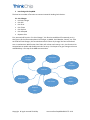
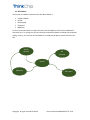
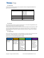
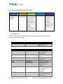
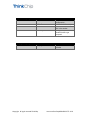
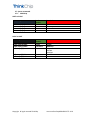
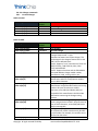
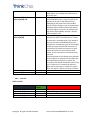
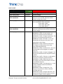
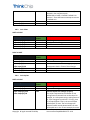
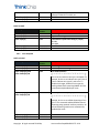
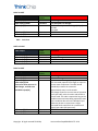
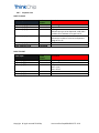
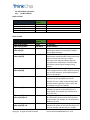
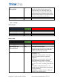
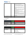
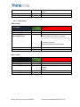
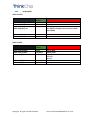
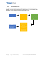
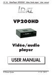
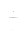
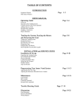
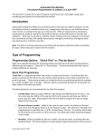
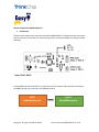
Reference Manual EasyMDB RS232-TTL 1 Introduction This document explains how to use the interface EasyMDB RS232-TTL and describe the connections and the necessary commands for communicating with Cash System MDB (Coin Changer and Bill Validator). The EasyMDB interface for RS232 or TTL permits to connect a device which operates according to the MDB protocol to the serial port of embedded system. HOST Embedded System Copyright All rigth reserved ThinkChip SLAVE EasyMDB interface User Interface EasyMDB RS232-TTL V2.0 2 Interfacing with EasyMDB The host has a number of functions to communicate with Vending Cash Devices: 2.1 Coin Changer Init Coin Changer Coin Poll Coin Error Coin Tubes Coin PayOut Coin Accepted Dispense Coin First, we need call Function “Init Coin Changer”, this function established if connected, yes it is, then give us all the information about Coin Changer, as Model, Serial Number, Country, etc. Then we need Poll Coin Changer, this function determines if there any change, like coin inserted and error in mechanisms. With function Coin Tubes, tell us how much money is in it, the function Coin Accepted we can enable and disable particular currency. Coin Payout is for give change to the user and MDB Stop, is for stop all the MDB communication. Init Coin Changer Coin Error Coin Accepted Coin Poll MDB Stop Coin Tubes Coin PayOut Dispense Coin Copyright All rigth reserved ThinkChip User Interface EasyMDB RS232-TTL V2.0 2.2 Bill Validator The function to establish communication with Bill Validator is: Init Bill Validator Bill Poll Bill Accepted Bill Stacker MDB Stop To star the communication we need call function Init Bill Validator, this function established if connected, yes it is, then give us all the information about Bill Validator has Model, Serial Number, Scaling, Country, etc. Once call Init Bill Validator, we need poll the device, with the function Bill Poll. Init Bill Validator Bill Accepted Bill Poll MDB Stop Copyright All rigth reserved ThinkChip Bill Stacker User Interface EasyMDB RS232-TTL V2.0 2.3 Data Format The data format (Start Bit, Data Bits, parity, Stop Bit) is software configurable BaudRate. The general data format is defined as: Parameter Baud Rate Description 9600 bauds (By default) 19200 bauds 34800 bauds 57600 bauds 115200 bauds 8 bits 1 bit 1 bit None Data bits Start Bits Stop Bits Parity 2.4 Link Layer The communication protocol is a packet-oriented protocol - all the data exchanged between two communication devices will be based on packet format. The data packet starts with the control character, there are two types of control character, ‘COIN’ and ‘BILL’ (0x02 and 0x03 hexadecimal value respectively) and ends with ‘FC’ (0xff hexadecimal value), which follows the 8-bit BCC checksum. Besides the checksum is used for error checking, character (byte). 2.5 Packet format There are two types of data packets. Command Message is the packet Send from the Host to the SLAVE device. The Reply Message is the packet Send from the reader to the Host. Packet format for Command Message (HOST to SLAVE) Device Command Data SYSTEM=0x01 COIN=0x02 BILL=0x03 These describe the action that will be realized. For example COIN_INIT=0x01 The Data Field is a stream of data with variable length, which depends on the Command word. There are also some COMMANDs have zero length of data field. Copyright All rigth reserved ThinkChip FC (Final character) FC=0xff Checksum BCC 8 bits Checksum is the last character to be sent, is calculated by adding all character, the checksum is not included in the summation. User Interface EasyMDB RS232-TTL V2.0 Packet format for Reply Message (SLAVE to HOST) Device Command Data SYSTEM=0x01 COIN=0x02 BILL=0x03 These describe the action order The Data Field is a stream of data with variable length, which depends on the Command word. There are also some COMMANDs have zero length of data field. FC (Final character) FC= 0xff Checksum BCC 8 bits Checksum is the last character to be sent, is calculated by adding all character, the checksum is not included in the summation. 2.6 Command Set The commands are grouped to different categories. Divided for the Devices, the command represent an action to be realized. Interface Settings (0x01) 0x02 MDB Stop Stop all communication with MDB devices Coin Changer (0x02) 0x01 Init Coin Changer 0x03 Coin Poll 0x05 Coin Tubes 0x07 0x08 Coin PayOut Coin Accepted 0x0a Coin Error 0x0b Coin Dispense To obtain changer level and configuration information. Indicates the changer activity. Indicates status of coin tube for coin PayOut Coin Changer Setting enable and disable coin type accepted This command requests the changer to report its current state of operation. Dispense coin, this action is for coin changer level 1 for pay out. Copyright All rigth reserved ThinkChip User Interface EasyMDB RS232-TTL V2.0 Bill Validator (0x03) 0x01 Init Bill Validator 0x02 0x03 Bill Poll Bill Stacker 0x04 Bill Accepted Display MDB (0x04) 0x04 Display Value Copyright All rigth reserved ThinkChip To obtain bill configuration. Indicate the bill activity Indicate the number of bills in the stacker. Setting enable and disable the bills type accepted. Display value cash inserted User Interface EasyMDB RS232-TTL V2.0 2.7 System commands 2.7.1 MDB Stop HOST to SLAVE Buffer Output Packet Format Device Command FC CHECKSUM Description Description Buffer Input[0]=0x01 Buffer Input[1]=0x02 Buffer Input[2] Packet Format Device Command Data Buffer Input[3]=FC Buffer Input[4]=CHK FC CHECKSUM Buffer Output[0]=0x01 Buffer Output[1]=0x02 Buffer Output[2]=FC Buffer Output[3]=CHK System MDB Stop FC=0xff SLAVE to HOST Buffer Input Copyright All rigth reserved ThinkChip System MDB Stop Response 0x01 OK 0x00 FAIL FC=0xff User Interface EasyMDB RS232-TTL V2.0 2.8 Coin Changer commands 2.8.1 Init Coin Changer HOST to SLAVE Buffer Output Buffer Output[0]=0x02 Buffer Output[1]=0x01 Buffer Output[2]=FC Buffer Output[3]=CHK Packet Format Device Command FC CHECKSUM Description Packet Format Device Command Data Description Coin Changer Init Coin Changer FC=0xff SLAVE to HOST Buffer Input Buffer Input[0]=0x02 Buffer Input[1]=0x01 Buffer Input[2] Buffer Input[3] to Buffer Input[5] Data Buffer Input[6] to Buffer Input[17] Data Buffer Input[18] to Buffer Input[29] Data Buffer Input[30] Data Buffer Input[31] Data Copyright All rigth reserved ThinkChip Coin Changer Init Coin Changer Level Changer Feature Level - 1 byte Indicates the feature level of the changer. This will distinguish the changers feature level to the VMC. Current defined levels: Level 2: Supports “core” command set. These are: RESET, STATUS, TUBE STATUS, POLL, COIN TYPE, and DISPENSE. Level 3: Supports level two and the EXPANSION command addition changer model number, manufacturer code, turning revision, etc. Manufacturer Code (3 bytes) Identification code for the equipment supplier. Sent as ASCII characters. Model Coin Changer (12 bytes) Manufacturer assigned model number and tuning number. All bytes must be sent as ASCII characters, zeros (30H) and blanks (20H) are acceptable. Each manufacturer should include information concerning the changer tuning revision. Serial Number Coin Changer (12 bytes) Factory assigned serial number. All bytes must be sent as ASCII characters, zeros (30H) and blanks (20H) are acceptable. Scaling Factor (1 byte) All accepted coin values must be evenly divisible by this number. For example, this could be set to 05H for the USA nickel. Decimal Places (1 byte) User Interface EasyMDB RS232-TTL V2.0 Buffer Input[32]= msb Buffer Input[33]= lsb Data Buffer Input[34] to Buffer Input[49] Data Buffer Input[50]=FC Buffer Input[51]=CHK FC CHECKSUM 2.8.2 Indicates the number of decimal places on a credit display. For example, this could be set to 02H in the USA. Country (2 bytes) The packed BCD country / currency code of the changer can be sent in two different forms depending on the value of the left most BCD digit. If the left most digit is a 0, the international Telephone Code is used to indicate the country that the changer is set-up for. For example, the USA code is 00 01H (Buffer Input[31] = 00 and Buffer Input[32] = 01). Coin Value Accepted (16 bytes) Indicates the value of coin types 0 to 15. Values must be sent in ascending order. This number is the coin's monetary value divided by the coin scaling factor. Unused coin types are sent as 00H. Unsent coin types are assumed to be zero. It is not necessary to send all coin types. Coin type credits sent as FFH are assumed to be vend tokens. That is, their value is assumed to worth one vend. The bytes position in the 16 byte string indicates the coin type(s). For example, the first byte sent would indicate the value of coin type 0, the second byte sent would indicate the value of coin type 1, and so on. For example, the USA coin types may be; Coin type 0 = nickel, Coin type 1 = dime, Coin type 2 = quarter, Coin type 3 = dollar. FC=0xff Coin Poll HOST to SLAVE Buffer Output Buffer Output[0]=0x02 Buffer Output[1]=0x03 Buffer Output[2]=FC Buffer Output[3]=CHK Packet Format Device Command FC CHECKSUM Copyright All rigth reserved ThinkChip Description Coin Changer Poll Coin Changer FC=0xff User Interface EasyMDB RS232-TTL V2.0 SLAVE to HOST Buffer Input Buffer Input[0]=0x02 Buffer Input[1]=0x03 Buffer Input[2]=msb Buffer Input[3]=lsb Packet Format Device Command Data Buffer Input[4] Data Buffer Input[5]=msb Buffer Input[6]=lsb Data Buffer Input[7] Data Copyright All rigth reserved ThinkChip Description Coin Changer Poll Coin Changer Value Coin Inserted (2 bytes) Amount of coins inserted, should be divided between Scaling Factor Value. Coin Routing (1 byte) Coin routing. 00b or 0x00: CASH BOX 01b or 0x01: TUBES 10b or 0x02: NOT USED 11b or 0x03: REJECT Coin Value Dispensed Manually (2 bytes) Amount of cash dispensed manually by Operator of Coin Changer Status Coin Changer (00000001b or 0x01) = Escrow request - An escrow lever activation has been detected. (00000010b or 0x02) = Changer Payout Busy - The changer is busy activating payout devices. (00000011b or 0x03) = No Credit - A coin was validated but did not get to the place in the system when credit is given. (00000100b or 0x04) = Defective Tube Sensor The changer has detected one of the tube sensors behaving abnormally. (00000101b or 0x05) = Double Arrival - Two coins were detected too close together to validate either one. (00000110b or 0x06) = Acceptor Unplugged - The changer has detected that the acceptor has been removed. (00000111b or 0x07) = Tube Jam - A tube payout attempt has resulted in jammed condition. (00001000b or 0x08) = ROM checksum error The changers internal checksum does not match the calculated checksum. (00001001b or 0x09) = Coin Routing Error - A coin has been validated, but did not follow the intended routing. (00001010b or 0x0a) = Changer Busy - The changer is busy and can’t answer a detailed command right now. (00001011b or 0x0b) = Changer was Reset - The changer has detected a Reset condition and has returned to its power-on idle condition. User Interface EasyMDB RS232-TTL V2.0 Buffer Input[8]=FC Buffer Input[9]=CHK 2.8.3 FC CHECKSUM (00001100b or 0x0c) = Coin Jam - A coin(s) has jammed in the acceptance path. (00001101b or 0x0d) = Possible Credited Coin Removal – There has been an attempt to remove a credited coin. FC=0xff Coin Tubes HOST to SLAVE Buffer Output Buffer Output[0]=0x02 Buffer Output[1]=0x05 Buffer Output[2]=FC Buffer Output[3]=CHK Packet Format Device Command FC CHECKSUM Description Packet Format Device Command Data Description Coin Changer Tube Status Coin Changer FC=0xff SLAVE to HOST Buffer Input Buffer Input[0]=0x02 Buffer Input[1]=0x01 Buffer Input[2]=msb Buffer Input[3]=lsb Buffer Input[4]=FC Buffer Input[5]=CHK 2.8.4 FC CHECKSUM Coin Changer Tube Status Coin Changer Value Cash in Tubes of Coin Changer (2 bytes) Total Amount Cash in Tubes of Coin Changer FC=0xff Coin PayOut HOST to SLAVE Buffer Output Buffer Output[0]=0x02 Buffer Output[1]=0x07 Buffer Output[2]=msb Buffer Output[3]=lsb Packet Format Device Command Data Copyright All rigth reserved ThinkChip Description Coin Changer PayOut Coin Changer Amount PayOut Coin Changer (2 bytes) This value is expressed as the number of coin scaling factors that would sum to the value. For example, in a USA system using a scaling factor of 05, if the change to be paid out is 75 cents, then Y1 will equal fifteen. That is, the sum of fifteen nickels equal 75 cents. The coin changer will determine which actual denominations of coins will be paid out. In the 75 cent example, the coins User Interface EasyMDB RS232-TTL V2.0 Buffer Output[4]=FC Buffer Output[5]=CHK FC CHECKSUM may be 3 quarters; or, 7 dimes & 1 nickel; or, 2 quarters & 2 dimes & 1 nickel, etc. FC=0xff SLAVE to HOST Buffer Input Buffer Input[0]=0x02 Buffer Input[1]=0x07 Buffer Input[2] Packet Format Device Command Data Buffer Input[3]=FC Buffer Input[4]=CHK FC CHECKSUM 2.8.5 Description Coin Changer PayOut Coin Changer Confirmation PayOut Coin Changer (1 byte) OK 0x01 FAIL 0x00 FC=0xff Coin Accepted HOST to SLAVE Buffer Output Buffer Output[0]=0x02 Buffer Output[1]=0x08 Buffer Output[2]=msb Buffer OutPut[3]=lsb Packet Format Device Command Data Description Coin Changer Coin Accepted Coin Changer Coin Enable(2 bytes) A bit is set to indicate a coin type is accepted. For example, bit 6 is set to indicate coin type 6, bit 15 is set to indicate coin type 15, and so on. To disable the changer, disable all coin types by sending a data block containing 0000H. All coins are automatically disabled upon reset. Buffer Output[4]=msb Buffer Output[5]=lsb Data Manually Coin Enable (2 bytes) A bit is set to indicate dispense enable. For example, bit 2 is set to enable dispensing of coin type 2. This command enables/disables manual dispensing using optional inventory switches. All manual dispensing switches are automatically enabled upon reset Buffer Output[6]=FC Buffer Output[7]=CHK FC CHECKSUM Copyright All rigth reserved ThinkChip FC=0xff User Interface EasyMDB RS232-TTL V2.0 SLAVE to HOST Buffer Input Buffer Input[0]=0x02 Buffer Input[1]=0x08 Buffer Input[2] Packet Format Device Command Data Buffer Input[3]=FC Buffer Input[4]=CHK FC CHECKSUM 2.8.6 Description Coin Changer Coin Accepted Coin Changer Confirmation PayOut Coin Changer (1 byte) OK 0x01 FAIL 0x00 FC=0xff Coin Error HOST to SLAVE Buffer Output Buffer Output[0]=0x02 Buffer Output[1]=0x0a Buffer Output[2]=FC Buffer Output[3]=CHK Packet Format Device Command FC CHECKSUM Description Packet Format Device Command Data Description Coin Changer Error Coin Changer FC=0xff SLAVE to HOST Buffer Input Buffer Input[0]=0x02 Buffer Input[1]=0x0a Buffer Input[2]=msb Buffer Input[3]=lsb If exist more than one error in Coin Changer, could be sent until Buffer Input[16] Buffer Input[X]=FC Buffer Input[X]=CHK FC CHECKSUM Copyright All rigth reserved ThinkChip Coin Changer Error Coin Changer Error Status Coin Changer (2 bytes) This command requests the changer to report its current state of operation. The VMC should periodically transmit the command approximately every 1 to 10 seconds. The changer reports its current state of operation in a 2 byte code, msb is the main code and lsb is the sub-code. The code is reported as long as the condition exists and stops being reported as soon as the condition does not exist. Multiple 2 byte codes may be sent in response to a single command which could result in a maximum of eight 2 byte codes (16 bytes total). FC=0xff User Interface EasyMDB RS232-TTL V2.0 2.8.7 Dispense Coin HOST TO SLAVE Buffer Output Buffer Output[0]=0x02 Buffer Output[1]=0x0b Buffer Output[2] Packet Format Device Command Data Buffer Output[3] Data Buffer Output[4]=FC Buffer Output[5]=CHK FC CHECKSUM Description Coin Changer Dispense Coin Coin Type Indicate coin type to be dispensed. Valid codes are 0H to FH to indicate coin types 0 to 15. Numbers of coins Indicate the number of coins to be dispensed. Range of 0 to 15 FC=0xff SLAVE TO HOST Buffer Input Buffer Input[0]=0x02 Buffer Input[1]=0x0b Buffer Input[2] Packet Format Device Command Data Buffer Input[3]=FC Buffer Input[4]=CHK FC CHECKSUM Copyright All rigth reserved ThinkChip Description Coin Changer Dispense Coin Response Data = 1 OK Data = 0 Fail FC=0xff User Interface EasyMDB RS232-TTL V2.0 2.9 Bill Validator commands 2.9.1 Init Bill Validator HOST to SLAVE Buffer Output Buffer Output[0]=0x03 Buffer Output[1]=0x01 Buffer Output[2]=FC Buffer Output[3]=CHK Packet Format Device Command FC CHECKSUM Description Packet Format Device Command Data Description Bill Validator Init Bill Validator FC=0xff SLAVE to HOST Buffer Input Buffer Input[0]=0x03 Buffer Input[1]=0x01 Buffer Input[2] to Buffer Input[4] Buffer Input[5] to Buffer Input[16] Data Buffer Input[17] to Buffer Input[28] Data Buffer Input[29] Data Buffer Input[30] Data Buffer Input[31]=msb Buffer Input[32]=lsb Data Buffer Input[33]= msb Buffer Input[34]= lsb Data Copyright All rigth reserved ThinkChip Bill Validator Init Bill Validator Manufacturer Code Bill Validator (3 bytes) Identification code for the equipment supplier. Sent as ASCII characters. Model Bill Validator (12 bytes) Manufacturer assigned model number and tuning number. All bytes must be sent as ASCII characters, zeros (30H) and blanks (20H) are acceptable. Each manufacturer should include information concerning the changer tuning revision. Serial Number Bill Validator (12 bytes) Factory assigned serial number. All bytes must be sent as ASCII characters, zeros (30H) and blanks (20H) are acceptable. Escrow Bill Validator (1 byte) Indicates the escrow capability of the bill validator. If Input = 0x00, the bill validator does not have escrow capability. If Input = 0xFF, the bill validator has escrow capability. Decimal Places Bill Validator (1 byte) Indicates the number of decimal places on a credit display. For example, this could be set to 02H in the USA. Scaling Factor Bill Validator (2 bytes) All accepted bill values must be evenly divisible by this number. For example, this could be set to 0064H for the USA. Stacker Capacity Bill Validator (2 bytes) Indicates the number of bills that the stacker will hold. For example, 400 bill capacity = 0190H. User Interface EasyMDB RS232-TTL V2.0 Buffer Input[35] to Buffer Input[50] Data Buffer Input[51]=FC Buffer Input[52]=CHK FC CHECKSUM 2.9.2 Bills Type Accepted (16 bytes) Indicates the value of the bill types 0 to 15. Values must be sent in ascending order. This number is the bill's monetary value divided by the bill scaling factor. Unused bill types are sent as 00H. Unsent bill types are assumed to be zero. FFH bills are assumed to be vend tokens. FC=0xff Bill Poll HOST to SLAVE Buffer Output Buffer Output[0]=0x03 Buffer Output[1]=0x02 Buffer Output[2]=FC Buffer Output[3]=CHK Packet Format Device Command FC CHECKSUM Description Packet Format Device Command Data Description Bill Validator Poll Bill Validator FC=0xff SLAVE to HOST Buffer Input Buffer Input[0]=0x03 Buffer Input[1]=0x02 Buffer Input[2]= msb Buffer Input[3]=lsb Buffer Input[4] Data Copyright All rigth reserved ThinkChip Bill Validator Poll Bill Validator Value Bills Inserted (2 bytes) Indicate the value total of bills inserted, the value should be divided between Scaling Factor Bill Validator for obtain the real value. Status Bill Validator (1 byte) (00000000b) = OK (00000001b) = Defective Motor - One of the motors has failed to perform its expected assignment. (00000010b) = Sensor Problem - One of the sensors has failed to provide its response. (00000011b) = Validator Busy - The validator is busy and can’t answer a detailed command right now. (00000100b) = ROM Checksum Error - The validator internal checksum does not match the calculated checksum. (00000101b) = Validator Jammed - A bill(s) has jammed in the acceptance path. User Interface EasyMDB RS232-TTL V2.0 Buffer Input[5]=FC Buffer Input[6]=CHK 2.9.3 FC CHECKSUM (00000110b) = Validator was reset - The validator has been reset since the last POLL. (00000111b) = Bill Removed - A bill in the escrow position has been removed by an unknown means. A BILL RETURNED message should also be sent. (00001000b) = Cash Box out of position - The validator has detected the cash box to be open or removed. (00001001b) = Validator Disabled - The validator has been disabled, by the VMC or because of internal conditions. (00001010b) = Invalid Escrow request - An ESCROW command was requested for a bill not in the escrow position. (00001011b) = Bill Rejected - A bill was detected, but rejected because it could not be identified. (00001100b) = Possible Credited Bill Removal – There has been an attempt to remove a credited (stacked) bill. FC=0xff Bill Stacker HOST to SLAVE Buffer Output Buffer Output[0]=0x03 Buffer Output[1]=0x03 Buffer Output[2]=FC Buffer Output[3]=CHK Packet Format Device Command FC CHECKSUM Description Packet Format Device Command Data Description Bill Validator Stacker Bill Validator FC=0xff SLAVE to HOST Buffer Input Buffer Input[0]=0x03 Buffer Input[1]=0x03 Buffer Input[2]= msb Buffer Input[3]=lsb Copyright All rigth reserved ThinkChip Bill Validator Stacker Bill Validator Stacker Capacity (2 bytes) Indicates stacker full condition and the number of bills in the stacker. msb lsb (Fxxxxxxx) (xxxxxxxx) F = 1 if stacker is full, 0 if not. User Interface EasyMDB RS232-TTL V2.0 Buffer Input[4]=FC Buffer Input[5]=CHK 2.9.4 FC CHECKSUM xxxxxxxxxxxxxxx = The number of bills in the stacker. FC=0xff Bill Accepted HOST to SLAVE Buffer Output Buffer Output[0]=0x03 Buffer Output[1]=0x04 Buffer Output[2]= msb Buffer Output[3]= lsb Packet Format Device Command Data Description Bill Validator Bills Accepted Bill Enable (2 bytes) Indicates what type of bills are accepted. Bill types are 0 to 15. A bit is set to indicate acceptance of bill type. Sending 0x00 disables the bill validator Buffer Output[4]=FC Buffer Output[5]=CHK FC CHECKSUM FC=0xff Description Buffer Input[0]=0x03 Buffer Input[1]=0x03 Buffer Input[2] Packet Format Device Command Data Buffer Input[3]=FC Buffer Input[4]=CHK FC CHECKSUM SLAVE to HOST Buffer Input Copyright All rigth reserved ThinkChip Bill Validator Stacker Bill Validator Bill Enable Confirmation 0x00 FAIL 0x01 OK FC=0xff User Interface EasyMDB RS232-TTL V2.0 2.10 Display MDB HOST to SLAVE Buffer Output Packet Format Device Command Data Description FC CHECKSUM FC=0xff Description Buffer Input[0]=0x04 Buffer Input[1]=0x01 Buffer Input[2] Packet Format Device Command Data Buffer Input[3]=FC Buffer Input[4]=CHK FC CHECKSUM Buffer Output[0]=0x04 Buffer Output[1]=0x01 Buffer Output[2]= msb Buffer Output[3]= lsb Buffer Output[4]=FC Buffer Output[5]=CHK Display MDB Display Value Value (2 bytes) The display has 4 digits, the max value is 9999 that is 99.99 SLAVE to HOST Buffer Input Copyright All rigth reserved ThinkChip Display MDB Display Value Display Value Confirmation 0x00 FAIL 0x01 OK FC=0xff User Interface EasyMDB RS232-TTL V2.0 2.11 Example communication This chapter explains the way of communicating with MDB Devices. The HOST send a function to the SLAVE, the SLAVE try to communicate with Cash Device, then wait for response, send to HOST the response. Now let’s see an example with Init Coin Changer Function. HOST Send Init Coin Changer Send SLAVE Receive Init Coin Changer Function and start communication with Coin Changer COIN CHANGER Init Settings and start reading coins Send Information of settings to SLAVE Send Send HOST Receive setting Information Send Copyright All rigth reserved ThinkChip SLAVE Receive Init Coin Changer Function and start communication with Coin Changer Send Information Setting to HOST User Interface EasyMDB RS232-TTL V2.0 History version manual V1.0 Date 05/2014 First revision manual V1.0.1 Date 06/2014 Added Dispense Coin command Add parameter Level in Init Coin command Eliminate the Baudrate command V2.0 Date 08/2014 Added Display command value Rev 2 of PCB updated Copyright All rigth reserved ThinkChip User Interface EasyMDB RS232-TTL V2.0