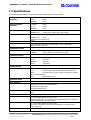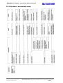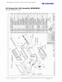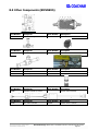
1
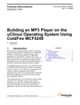
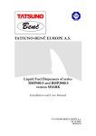
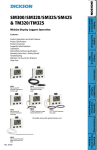
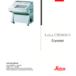
Coachair BMS38BX1 OPERATION, MAINTENANCE & OVERVIEW MANUAL Heat-Cool Model with Drivers Unit Document Number: SM424-3381 Revision No.: 00 Issue Date: Oct 2006 Uncontrolled Copy: Please refer to the Network for the current issue of this manual BMS38BX1 A/C System – Operation & Overview Manual Rev Date Description 00 Oct 30, 2006 First Release, CR 12098 Released 31 October, 2006 Winfried Wirfler Document Number: SM424-3381 Issue Date: October 2006 Uncontrolled Copy: Please refer to the Network for the current issue of this manual Page 2 BMS38BX1 A/C System – Operation & Overview Manual NOTICE The information in this manual is subject to change without notice. Coachair shall not be liable for technical or editorial errors or omissions contained herein. No part of this manual may be photocopied or reproduced in any form without prior consent from Coachair. Coachair CUSTOMER SUPPORT INQUIRIES Australia Malaysia China Telephone: +61 2 9830 7132 +60 3 61208760 +86 519 5125568 Facsimile: +61 2 9672 1082 +60 3 61208712 +86 519 5113086 3 Distillers Place Huntingwood 2148 Australia Lot No. 9, Jalan Empat, Address: Kawasan Perindustrian Selayang, Off Jalan Besar, Bandar Selayang, 68100 Selangor D.E. Malaysia No. 268 West Hehai Road Xinbei District, Changzhou City Jiangsu Province - P. R. China 213000 WEB - www.aitransit.com Document Number: SM424-3381 Issue Date: October 2006 Uncontrolled Copy: Please refer to the Network for the current issue of this manual Page 3 BMS38BX1 A/C System – Operation & Overview Manual IMPORTANT INFORMATION Use R134a Refrigerant Only! The A/C system is designed for use with R134a refrigerant. Do not use any other refrigerant. The use of any other refrigerant may result in damage to the A/C unit and/or compressor. WARNING Use Ester Oil Only! The A/C system is designed for use with ester compressor oil. Do not use any other lubricating oil. The use of incorrect oil may result in damage to the A/C unit and/or compressor. WARNING Handle Electronics With Care! WARNING * Do not attempt to remove, repair, or handle the climate control panel or any components in any way without referring to the correct procedures. The electrical control panel houses sensitive equipment that may be damaged if handled incorrectly. Refer to the CCC007* Climate Control System Manual for electronics service details. NOTE Temperature Probes , CAUTION , CAUTION Each temperature probe in the unit is factory calibrated. Use Probes as they have been allocated. DO NOT swap or mix the probes, as this may lead to unit damage and faulting. 24V DC ONLY This unit is designed for a 24V DC electrical circuit ONLY. Do not under any circumstances use another voltage, as this may cause unit damage and faulting. There is power to the motors all the time. Never attempt to do repairs on motors or motor wiring without manually breaking the correct circuit breaker first. WARNING , CAUTION , Black Heat Sink The black heat sink built onto the ESP109 PCB is at earth potential. DO NOT, under any circumstances, place an earth or a bridge circuit on the heat sink, as this will cause serious unit damage. DO NOT use a test light. Use a suitable multimeter only! CAUTION , DO NOT push the red reset button for more than 2 seconds, as this could provide unintentional access to the CCC007* memory settings. CAUTION Document Number: SM424-3381 Issue Date: October 2006 Uncontrolled Copy: Please refer to the Network for the current issue of this manual Page 4 BMS38BX1 A/C System – Operation & Overview Manual CONTENTS SECTION 1: - System Details ............................................................... 6 1.1 Introduction ..................................................................................................... 6 1.2 Specifications ................................................................................................... 7 1.3 System Layout ................................................................................................. 8 1.4 System Parameters .......................................................................................... 9 1.5 Air Flow ......................................................................................................... 11 1.6 Refrigeration System....................................................................................... 13 1.7 Heating System .............................................................................................. 17 1.8 Electrical System ............................................................................................ 17 SECTION 2: - Installation ................................................................. 19 2.1 Installation Checklist ....................................................................................... 19 2.2 Unit Inspection............................................................................................... 19 2.3 Ducting & Vent Distribution System.................................................................. 20 2.4 Unit Mounting ................................................................................................ 21 2.5 Condensate Drains.......................................................................................... 21 2.6 Refrigeration Piping ........................................................................................ 22 2.7 Heating System Components ........................................................................... 22 2.8 Electrical Installation ...................................................................................... 23 SECTION 3: - Testing and Commissioning........................................... 26 SECTION 4: - Operating the A/C Unit ................................................. 27 SECTION 5: - Trouble Shooting.......................................................... 28 SECTION 6: - Maintenance Schedule .................................................. 33 SECTION 7: - Maintenance Procedures ............................................... 33 7.1 Pumping Down the System.............................................................................. 33 7.2 Reclaiming Refrigerant .................................................................................... 33 7.3 Pressure Testing ............................................................................................ 33 7.4 System Evacuation ......................................................................................... 33 7.5 Refrigerant Charging ...................................................................................... 33 7.6 Safety Device Checks ...................................................................................... 34 SECTION 8: - Spare Parts .................................................................. 35 8.1 Compressor Area (BMS38BX1) ......................................................................... 35 8.2 Drivers Unit Dash Panel................................................................................... 35 8.3 Evaporator Unit Assembly (BFW5BX5) .............................................................. 36 8.4 Driver’s Unit Assembly (BMV5BX5) ................................................................... 37 8.5 Other Components (BMV5BX5) ........................................................................ 38 Document Number: SM424-3381 Issue Date: October 2006 Uncontrolled Copy: Please refer to the Network for the current issue of this manual Page 5 BMS38BX1 A/C System – Operation & Overview Manual SECTION 1: - Sys tem D eta i l s 1.1 Introduction This manual is a guide to the operation, maintenance and spare parts for the BMS38BX1 bus air conditioning system manufactured by Coachair as specifically developed for Bus & Coach International. The BMS38BX1 air conditioning system consists of a high performance XT175 roof top A/C system for passenger comfort combined with a BMV5BX5 driver’s A/C system for driver comfort and demisting the windscreen. The BMS38BX1 air conditioning system is a ‘split system’ comprising of components that are designed to be integrated into the bus during its manufacture. The BMS38BX1 system includes the following primary components (units): A roof mounted evaporator/condenser unit (XT175) providing A/C (cooling and heating) for the passenger area. One under dash type evaporator unit (BFW5BX5) and associated piping and harnesses (collectively referred to as BMV5BX5) providing A/C (cooling and heating) and demisting airflow; An off-engine mounted compressor. Two driver's dash panels each controlling either the roof unit or the Driver’s system. Generic installation fittings. The BMS38BX1 system has the following key features: Light-weight construction. Standard operating voltage of 24 V DC. Use of environmental friendly R134a refrigerant. Efficient use of engine heat for heating requirements. 1.1.1 Hierarchy of Manuals The BMS38BX1 A/C system units are drawn from the Coachair product family. Manuals already exist for the XT roof top unit and these have been retained as discrete documents to allow timely updates of information as products are refined and improved. There are significant differences between the driver’s unit described in the existing manual (SM348 2793 Dash A/C Unit – Installation, Operation & Maintenance Manual) and the BCI unit. As such the relevant information from that manual plus any additional information has been incorporated into this manual. Manual Description BMS38BX1 Complete Bus A/C System SM424 3381 BMS38BX1 Operation & Maintenance & Overview Manual Purpose Overview of A/C System and Special items XT175 Roof Top Unit SM417 3283 XT Bus & Coach A/C – Installation, Operation & Maintenance Manual Installation, Operation & Maintenance Information SM425 3283 XT A/C Unit – Spare Parts Manual Spare Parts SM423-3283 CCC007* Climate Control System Manual Operation & Control BMV5BX5 Drivers Unit SM424 3381 BMS38BX1 Operation & Maintenance & Overview Manual Installation, Operation, Maintenance & Spare Parts Information 09704 FKX50/775K Bock Compressor Manual Maintenance of Bock Compressor KK73.1 Lang Clutch Operating Instructions Maintenance of Lang Clutch Other Document Number: SM424-3381 Issue Date: October 2006 Uncontrolled Copy: Please refer to the Network for the current issue of this manual Page 6 BMS38BX1 A/C System – Operation & Overview Manual 1.2 Specifications The following specifications are correct for the A/C system at the time of printing. Cooling Capacity (nominal) Combined: - 40 kW @ 35°C ambient, 27/19°C DB/WB Mixed Air XT175: BMV5BX5: - 35 kW - 5 kW Heating Capacity (nominal) Combined: - 42 kW XT175: - 38 kW BMV5BX5: - 4 kW XT175 Unit: BFW5BX5 Unit: - 3810mm long x 1940mm wide x 235mm high - 350mm high x 500mm wide x 350mm deep XT175 Unit: - 265 kg BFW5BX5 Unit: - 14 kg Dimensions Weight Refrigerant Compressor Compressor Clutch Airflow Operating Voltage Current Draw Condenser Unit Evaporator Unit Compressor with Clutch: 54 kg R134a Bock FKX50/775K reciprocating 6 cylinder design ~ 775 cc, engine driven. Maximum speed 3,500 rpm Lang KK73.1.23 2xSPB Ø 160mm OD electro-magnetic XT175: BFW5BX5: - 1,444 l/s (5,200 m3/hr) at high speed (free blow) - 200 l/s (720m3/hr) at high speed (free blow) 24 V DC nom. Max. 30 V DC cont., 45 V DC momentary, 20 V DC Min. Combined: - 77A (max.) XT175: - 62A (max.) BFW5BX5: - 12A (max.) Clutch: - 2.6A (max.) See SM417 manual. For XT see SM417 Manual. For Drivers Unit: Coil: 1-off rifle copper tube with high efficiency aluminium fins Motor: 1-off medium duty, long life, permanent magnet type, double shaft, steel ball bearings. Expansion Valve Drier Receiver Safety Features Fans: 2-off double inlet rotor. For XT see SM417 Manual. For Drivers Unit: Internally equalized block valve. See SM417 manual. High and low pressure cut-out safety switches Electrical de-ice thermostat Electrical protection fuses Climate Controller Fresh air Casing For XT see SM417 Manual. For Drivers Unit: Driver controlled modulating water valve. See SM417 manual. For XT see SM417 Manual. For Drivers Unit: Primarily constructed of 2.0 mm aluminium ensuring resistance to corrosion and physical damage due to its robust design. Corrosion Protection For XT see SM417 Manual. For Drivers Unit: The casing is chemically prepared for paint application to all internal and external surfaces. Lubricant Ester Oil Type – Fuchs Reniso Triton SE 55 (Or Equivalent). Document Number: SM424-3381 Issue Date: October 2006 Uncontrolled Copy: Please refer to the Network for the current issue of this manual Page 7 BMS38BX1 A/C System – Operation & Overview Manual 1.3 System Layout The typical configuration of the installed BMS38BX1 A/C system and it various components are shown in the following diagram: Drawing No. T3381007 Issue A 1.3.1 XT175 Roof Top Unit Drawing No. T3381002 Issue 00 Document Number: SM424-3381 Issue Date: October 2006 Uncontrolled Copy: Please refer to the Network for the current issue of this manual Page 8 BMS38BX1 A/C System – Operation & Overview Manual 1.4 System Parameters 1.4.1 XT175 Roof Top Unit Drawing No. T3381001 Issue 00 Document Number: SM424-3381 Issue Date: October 2006 Uncontrolled Copy: Please refer to the Network for the current issue of this manual Page 9 BMS38BX1 A/C System – Operation & Overview Manual 1.4.2 BFW5BX5 Evaporator Unit Drawing No. T3381501 Issue 00 Document Number: SM424-3381 Issue Date: October 2006 Uncontrolled Copy: Please refer to the Network for the current issue of this manual Page 10 BMS38BX1 A/C System – Operation & Overview Manual 1.5 Air Flow The XT175 roof top and Driver’s unit are not connected on the air side. Refer to the SM417 manual for the XT Unit. The Driver’s unit utilises cooling and heating functions to deliver conditioned air to the driver and/or windscreen as determined by the control settings. The unit is designed to be mounted under the dash in front of the bus driver. This positioning is shown in Section 1.3 - System Layout. Drawing No. T3381502 Issue 00 When operational the unit produces the following airflow: Return air from the bus cabin is drawn by the supply fan through the return air filter (Supplied by the Bus Body Builder) into the unit. The air is conditioned as it passes through the evaporator and heater coils inside the unit. The evaporator coil cools and dehumidifies the air. The heater coil heats the air. The type and amount of air conditioning provided is controlled by the driver according to the water valve setting. The conditioned supply air is discharged from the unit through the A/C or DEMIST outlets by an electrically operated damper. This switches the main airflow between the driver outlets and the windscreen outlet. Five air outlets on the top of the unit are provided for supplying air to the windscreen during DEMIST mode. The airflow from these outlets is to be ducted by the bus body builder towards the windscreen. Four air openings are provided on the return air side of the unit for supplying air to the driver during A/C mode. The airflow from this outlet is to be ducted by the bus body builder towards the driver face / body area. One foot outlet on the side of the unit supply air during A/C and DEMIST modes. In A/C and DEMIST modes air exits from the two side outlets. The airflow from the two side outlets is not affected by the position of the shutter. Document Number: SM424-3381 Issue Date: October 2006 Uncontrolled Copy: Please refer to the Network for the current issue of this manual Page 11 The airflow from these outlets is to be ducted by the bus body builder towards the driver’s feet area (or may be blocked off as required). Document Number: SM424-3381 Issue Date: October 2006 Uncontrolled Copy: Please refer to the Network for the current issue of this manual Page 12 BMS38BX1 A/C System – Operation & Overview Manual 1.6 Refrigeration System The refrigeration system for the BCI system is based on the XT system described in the SM417 manual. There is a 1/2 liquid line take-off in the XT unit which supplies cooled refrigerant to the BFW5BX5 driver’s evaporator Unit. The suction line from the driver’s unit then returns, under the passenger floor, to the engine mounted compressor. A solenoid valve is used to stop flow to the Driver’s unit when cooling is not required. This solenoid valve is operated as a de facto compressor clutch for the driver’s unit. 1.6.1 Refrigeration Piping and Connections Drawing No. T3381005 Issue A Component List Document Number: SM424-3381 Issue Date: October 2006 Uncontrolled Copy: Please refer to the Network for the current issue of this manual Page 13 BMS38BX1 A/C System – Operation & Overview Manual Piping Layout Document Number: SM424-3381 Issue Date: October 2006 Uncontrolled Copy: Please refer to the Network for the current issue of this manual Page 14 BMS38BX1 A/C System – Operation & Overview Manual 1.6.2 Major Components COMPONENT Compressor Condenser Coils Condenser Fans Pressure Relief Valve DETAILS AND FUNCTION Compresses low pressure, low temperature refrigerant vapour to a high pressure, high temperature gas. Transfer heat from the refrigerant into the ambient air, causing the high pressure, high temperature gas to condense into a high-pressure liquid. Draw air in the side grilles through the condenser coils and force it out through the other side grilles. In case of high pressure the valve opens at 2,900 kPa to vent excess pressure to atmosphere. The valve reseats at when the system pressure then reduces to 2,700 kPa. Receiver Tank Ball Valve Solenoid Valve Stores and separates high pressure liquid from the gas/liquid mixture incoming from the condenser coils, to ensure that only liquid refrigerant passes on to the TX valve. Together with the solenoid valve, enables the Filter/Drier to be isolated from the system for removal & replacement without loss of refrigerant from the system. Eliminates liquid refrigerant migration from the low-pressure side of the system to compressor sump during off cycle, protecting the compressor against damaging liquid slugging. The solenoid valve is in a closed position when the A/C system is off. Filter/Drier Filters and removes moisture and foreign particles from the refrigerant. The valves either side of the Filter/Drier enable easy replacement with reduced gas loss. Sight Glass Indicates the refrigerant level and moisture content in the system. The positioning of the sight glass allows for easy viewing from inside the bus saloon area through the Return Air Plenum. Thermal Expansion (TX) Valve Evaporator Coils Regulates the refrigerant flow into the evaporator coil by expanding the liquid from a high pressure, high temperature liquid to a low temperature, low pressure liquid. Transfers heat from the air to the refrigerant, causing the low pressure, low temperature liquid to evaporate in the evaporator into a low-pressure vapour. As air passes through the coil it is cooled and dehumidified. Evaporator Blowers Check Valve Pressure Regulator Unit Connections Compressor Connections Draws air into the unit through the return air & fresh air openings; through the evaporator coils – and directing it into the supply air openings. Prevents return of liquid refrigerant from the condenser to the compressor when the A/C system is inoperative. Ensures not to much refrigerant cycles through the Driver’s units. Suction and discharge refrigeration pipelines are connected to the unit by leak-proof flanges. The connections are made at the unit base inside the vehicle on the nearside or off-side air supply roof opening, or at the back of the unit outside the vehicle. Piping is connected to the compressor via hoses with flange connections. Document Number: SM424-3381 Issue Date: October 2006 Uncontrolled Copy: Please refer to the Network for the current issue of this manual Page 15 BMS38BX1 A/C System – Operation & Overview Manual 1.6.3 Safety Devices High and Low Pressure Switches The compressor high and low-pressure switches on the compressor feed signals to the Coachair Climate Controller. If the refrigeration system pressures become abnormally high or low the climate controller will cut out the clutch. LP Switch Cut-out: 40 kPa Cut-in: 175 kPa HP Switch Cut-out: 2,070 kPa Cut-in: 1,380 kPa 1.6.4 Compressor The Bock FKX50/775K compressor is recommended to be used with the A/C system. Further details can be found in the compressor manual and at www.bock.de. Compressor Bock FKX50K/775K Displacement per rev (cc) 775 Speed Range (rpm) 500 – 3,500 Cylinders 6 Weight (kg) 42 Oil Charge (litres) 2.6 Capacity Control 100% / 67% / 33% Document Number: SM424-3381 Issue Date: October 2006 Uncontrolled Copy: Please refer to the Network for the current issue of this manual Page 16 BMS38BX1 A/C System – Operation & Overview Manual 1.6.5 Clutch The Lang KK73.1.23 160mm diameter electromagnetic clutch is recommended to be used with the A/C system. Further details can be found in the compressor manual and at wwwealang.com . The cross section of a typical clutch is illustrated below. 1.7 Heating System The XT175 roof top and Driver’s units heating systems can operate independently. Refer to the SM417 manual for how a typical heating system works. The booster pump is controlled by the XT75 climate control system but is typically not required for the Driver’s unit when it is operating alone. 1.8 Electrical System Refer to the SM417 manual for the XT Unit. The XT175 roof top and Drivers Unit are not connected electrically. The Driver’s Unit requires the XT175 Unit to be in cooling mode (with the compressor clutch engaged) for then to provide cooling. All system operations are controlled by the dash panel and the relays on the evaporator unit (Refer to diagram in the Section 2.8 – Electrical Installation). The evaporator coil thermostat allows the system to disengage the electro-magnetic compressor clutch should the temperature drop too low. This is intended to prevent ice from forming on the coil. Once the coil temperature rises clutch operation is re-enabled. 1.8.1 Power Supply UNIT VOLTAGE IS 24 V DC. The power supply line is the red cable in the 6 pin plug from the evaporator unit to the bus battery. Coachair recommends that a 25A slow blow fuse is installed on the power supply line as close as possible to the battery pack. (See Section 2.8.4 – Connect A/C System to the Bus). Document Number: SM424-3381 Issue Date: October 2006 Uncontrolled Copy: Please refer to the Network for the current issue of this manual Page 17 BMS38BX1 A/C System – Operation & Overview Manual 1.8.2 Ground Connection The ground line is a black cable in the 6 pin plug from the evaporator unit to the bus frame/chassis. (See Section 2.8.4 – Connect A/C System to the Bus). Use a Multi-Meter Only! DO NOT make a bridge connection between any terminals or use a test light. This may cause serious electrical damage to the unit and/or injury. Use a multi-meter only! 1.8.3 Temperature Probes Evaporator (De-Ice) Probe The evaporator thermostat has a probe which is inserted into the fins of evaporator coils to measure the actual coil temperature. The de-ice probe are housed in stainless steel shafts to provide adequate strength & protection – as well as optimum contact with the coil fins. 1.8.4 De-Ice Control Should the evaporator coil temperature drop too low ice may begin to form on the coils blocking airflow and compromising A/C unit operation. To prevent this situation, the thermostat reduces cooling by cutting power to the clutch (and unloaders if available) when the coil temperature drops too low. 1.8.5 Driver's Dash Control Panel The driver manually controls the A/C system with the driver dash panel. The Dash Panel is connected to the relay harness on the evaporator unit and features controls for: Selecting the operating mode of the A/C system between OFF, DEMIST, and A/C Adjusting the blower fan speed Setting the desired amount of reheating of the conditioned air 1.8.6 (Refer to 3.1.1De-Ice Operation (Driver’s Unit) A thermostat probe is located in the fins of the evaporator coil. The coil temperature is monitored by the thermostat to detect low temperatures and prevent icing of the coils. To check the de-ice operation run the A/C system. Open the evaporator access cover or stop the evaporator blowers by removing their relays from the circuit. This will cause the evaporator coil temperature to drop quickly and activate the safety cut out. As the coil/de-ice probe temperature drops the solenoid valve should close at -3°C. As the coil/de-ice probe temperature rises the solenoid valve should open at +1°C. If necessary adjust the thermostat so that the valve operates at the required temperature. Operating the A/C Unit) 1.8.7 Harness Arrangement Refer to Section 2.8.2 - BMV5BX5 Harness Arrangement Detail. 1.8.8 Wiring Diagram Refer to Section 2.8.3 - BMV5BX5 Wiring Diagram. Document Number: SM424-3381 Issue Date: October 2006 Uncontrolled Copy: Please refer to the Network for the current issue of this manual Page 18 BMS38BX1 A/C System – Operation & Overview Manual SECTION 2: - Ins ta l l a ti o n Refer to the SM417 manual for the XT Unit. 2.1 Installation Checklist Check off all items. Inspect the evaporator units and loose items. Check for correct preparation of mounting locations. Check the ducting and distribution vent system. Install the evaporator and loose items. Install the return air grille. Install the condensate drains. Install refrigeration piping. Connect the piping to the evaporator and piping panels. Connect the piping to the XT system. Install heating system components. Install driver dash panel. Install electrical harnesses. Pressure test of the system. Evacuate the system. Charge the system with refrigerant. Finalise heating system installation. Check safety devices. Complete post-installation checklist. 2.2 Unit Inspection Before beginning the installation, perform a visual inspection of the units. Check to make sure no damage has occurred during shipping: No external damage to the casing. No damage to coil fins or other external components. 5 - 10 mm clearance between the condenser fan blade and top grille. REPORT ANY VISIBLE DAMAGE! Do Not Remove Sealing Caps! Do not remove the refrigeration sealing caps before installing the unit. The sealing flange is to be removed immediately before connecting the body piping. As supplied, the unit is sealed and pressurised to 350-400 kPa. Document Number: SM424-3381 Issue Date: October 2006 Uncontrolled Copy: Please refer to the Network for the current issue of this manual Page 19 BMS38BX1 A/C System – Operation & Overview Manual 2.3 Ducting & Vent Distribution System An appropriately designed bus air ducting and distribution system is essential for efficient and trouble-free operation of the A/C system. Use the guidelines given in SM417. 2.3.1 Return Air Interface Six bolts are used to secure the return air duct to the Unit. The interface is shown below. Drawing No. T2793004 Issue 00 2.3.2 Vent Arrangement Document Number: SM424-3381 Issue Date: October 2006 Uncontrolled Copy: Please refer to the Network for the current issue of this manual Page 20 BMS38BX1 A/C System – Operation & Overview Manual 2.3.3 Sufficient non-closing type relief vents should be provided for constant air distribution to the windscreen, head and feet regions (Refer to Section 1.4.2 - BFW5BX5 Evaporator Unit Drawing No. T3381501 Issue 00 Document Number: SM424-3381 Issue Date: October 2006 Uncontrolled Copy: Please refer to the Network for the current issue of this manual Page 21 BMS38BX1 A/C System – Operation & Overview Manual ). Document Number: SM424-3381 Issue Date: October 2006 Uncontrolled Copy: Please refer to the Network for the current issue of this manual Page 22 Document Number: SM424-3381 Issue Date: October 2006 Uncontrolled Copy: Please refer to the Network for the current issue of this manual Page 23 BMS38BX1 A/C System – Operation & Overview Manual 2.3.4 Seal the Air Openings Seal the return air and supply air openings against water and air leakages, using a good quality non-drying type sealant. This seal ensures there is no air leakage or foreign matter (water, dust) can enter into the bus from this area. 2.3.5 Return Air Grille Install the return air grille in the return air opening. If the return air grille (and filter) assembly is to be provided by the body builder or installer, the following recommendations should be followed: The grille should be of a hinged or removable type so as to provide easy access into the unit evaporator section. The return air filter restriction should be less than 30 Pa @ 1.5 m/s air velocity. BMS38BX1 A/C System – Operation & Overview Manual 2.4 Unit Mounting Refer to the SM417 manual for the XT Unit. The driver’s unit is secured to the bus via 4 brackets (2 at the front and 2 at the rear). Sufficient clearance is required at the back of the unit to allow the access cover to be removed for access to the de-ice thermostat and evaporator motor. Typically the unit must be removed from the return air side so the bulkhead it is attached to must also be removable or an alternate method of removal, say by taking the bonnet off the bus, must be identified. Drawing No. T3381507 Issue 00 2.5 Condensate Drains Refer to the SM417 manual for the XT Unit. Included with the driver’s unit are: 16mm PVC pipe 2x aluminium tubes 2x Drain nozzles 4 hose clips The standard configuration of drain hoses is shown below. Document Number: SM424-3381 Issue Date: October 2006 Uncontrolled Copy: Please refer to the Network for the current issue of this manual Page 25 BMS38BX1 A/C System – Operation & Overview Manual Drawing No. T3381508 Issue 00 When installing drain hoses; the following notes must be adhered to: Route drain hoses to the bottom of the bus but to an area protected from road dirt and mechanical damage. Do not route the flow line uphill. Use correct size hose clamps and tighten securely. Make sure that there are no kinks or restrictions in the hoses at any point. Install drain nozzles to prevent air drawing up the drain hoses. 2.6 Refrigeration Piping The diagram in Section 1.6.1 – Refrigeration Piping and Connections shows the refrigeration piping circuit. Refer to SM417 manual for typical detail on installing and connecting refrigeration piping. 2.6.1 Refrigeration Piping Considerations For installation of the refrigeration piping Coachair recommends the following: Only use the recommended pipe sizes: SUCTION PIPING: 1 3/8” OD copper (XT175 unit) 7/8” OD copper [5/8” in vertical rise] (BFW5BX5) DISCHARGE PIPING: 1 1/8" OD copper LIQUID LINE: 1/2” OD copper (BMV5BX5 unit) 2.6.2 Suction & Discharge Piping Panels The driver’s unit has two piping panels supplied loose. These contain the components required for the suction and discharge lines for the driver’s unit. The water modulating valve is also included on the suction panel. These panels should be installed and connected as per the refrigeration diagram. Drawing No. T3381501 Issue 00 Drawing No. T3381502 Issue 00 2.7 Heating System Components Refer to SM417 manual for typical water piping details. The XT175 and BMV5BX5 unit should use 3/4” water pipe. The booster pump should be installed between the motor and the take off to both units. See the diagram in Section 1.6.1 – Refrigeration Piping and Connections Document Number: SM424-3381 Issue Date: October 2006 Uncontrolled Copy: Please refer to the Network for the current issue of this manual Page 26 BMS38BX1 A/C System – Operation & Overview Manual 2.8 Electrical Installation Refer to the SM417 manual for the XT Unit. 2.8.1 Typical Wiring Harness Layout BMS38BX1 Drawing No. T3381008 Issue A 2.8.2 BMV5BX5 Harness Arrangement Detail The harness arrangement for the driver’s unit is shown below. Drawing No. AS338150 Issue A Document Number: SM424-3381 Issue Date: October 2006 Uncontrolled Copy: Please refer to the Network for the current issue of this manual Page 27 BMS38BX1 A/C System – Operation & Overview Manual 2.8.3 BMV5BX5 Wiring Diagram The wiring for the driver’s unit is shown below. Document Number: SM424-3381 Issue Date:Number: OctoberSM424-3381 2006 Document Issue Date: October 2006 Uncontrolled Copy: Please refer to the Network for the current issue of this manual Uncontrolled Copy: Please refer to the Network for the current issue Page of this27manual Page 28 BMS38BX1 A/C System – Operation & Overview Manual 2.8.4 Connect A/C System to the Bus The driver’s unit is powered through a six pin plug on the main harness. The wiring on the bus required for this plug is shown below. The plug on the bus is a Carroll male QK6BLT connecting to the equivalent female plug on the relay harness. 2.8.5 Install Dash Panel and Harness The dash panel is to be installed on the vehicle dashboard with the cut out shown below. Fix the dash panel using the four mounting holes. The dash harness connects from the dash panel to the relay harness on the evaporator unit control. Run the cable along the shortest path. Secure the cable against vibration and shock. Keep the cable away from heat and electrical emissions. Do not run the dash harness with the battery cable or any other electrical wiring unless it is unavoidable. 2.8.6 Install Solenoid Valve Wiring The solenoid valve acts as surrogate compressor (clutch) for the driver’s unit. A 2 pin Carroll male QK2BSL connector is required on the cable connecting to the driver’s unit. Wiring should be as shown in Section 2.8.3 - BMV5BX5 Wiring Diagram 2.8.7 Install Water Modulation Valve wiring The Coachair supplied cabling is used to connect the water modulation valve. Harnesses should be as shown in Section 2.8.2 - BMV5BX5 Harness Arrangement Detail 2.8.8 Check Operation of All Fans Check the operation and rotating direction of the evaporator blower immediately after installing the electrical harnesses, before refrigerant charging. BMS38BX1 A/C System – Operation & Overview Manual SECTION 3: - Testing Commissioning and The commissioning of the A/C system must be carried out by Coachair Service personnel or authorised agents. Refer to the SM417 manual for Testing and Commissioning details. The XT175 unit must be in cool mode for the Driver’s A/C system cooling to be tested. To balance the systems the pressure regulator on the Driver’s Units suction line should be adjusted. On initial start up this should be in the fully open position to provide maximum flow to the Driver’s Units 3.1.1 De-Ice Operation (Driver’s Unit) A thermostat probe is located in the fins of the evaporator coil. The coil temperature is monitored by the thermostat to detect low temperatures and prevent icing of the coils. To check the de-ice operation run the A/C system. Open the evaporator access cover or stop the evaporator blowers by removing their relays from the circuit. This will cause the evaporator coil temperature to drop quickly and activate the safety cut out. As the coil/de-ice probe temperature drops the solenoid valve should close at -3°C. As the coil/de-ice probe temperature rises the solenoid valve should open at +1°C. If necessary adjust the thermostat so that the valve operates at the required temperature. Document Number: SM424-3381 Issue Date: October 2006 Uncontrolled Copy: Please refer to the Network for the current issue of this manual Page 30 BMS38BX1 A/C System – Operation & Overview Manual S E C T I O N 4 : - O p e r a t i n g t h e A / C U n i t Refer to SM417 & SM423 manuals for operating the XT175 Unit. Where there is a conflict between instructions the XT175 instruction should take priority. For the Driver’s A/C system to provide cooling the XT175 must be put into A/C mode and be operating. 4.1.1 Using the Dash Panel Coachair supplies a dash panel for driver control of the driver’s unit. The dash panel features three switches and a rotary control. Mode Switch Selects the A/C system operating mode between OFF, DEMIST, and A/C. Set switch to upper position. Mode Lights Fan Speed Switch Set switch to middle position. Set switch to lower position. In DRIVER mode the unit provides ventilation / cooling / heating operation depending on the temperature control setting and the return air temperature. Fans operate at the selected speed. In DEMIST mode the unit operates at the heating level selected, with or without cooling, depending on the temperature control setting and the return air temperature. Fans operate at the selected speed. An output signal for an external damper motor is also provided. Illuminate when the switch is set to DEMIST or A/C to indicate operation. Selects the operating speed of the fan blowers during DEMIST and A/C modes. Set switch to upper position. Set switch to middle position. Set switch to lower position. Temperature Control Provides for adjustment of the set point temperature. A/C On/ Off Switch Illuminates when the A/C system is providing cooling operation. When switched on, the compressor clutch engages, regardless of ambient conditions. 4.1.2 Damper Motor Controller There are three lights (green, orange & red) on the damper motor controller which operate as follows: Green Blinking – Damper moving to top position Green Solid – Damper in top position Orange Blinking – Damper moving to bottom position Orange Solid – Damper in bottom position Red – fault present Document Number: SM424-3381 Issue Date: October 2006 Uncontrolled Copy: Please refer to the Network for the current issue of this manual Page 30 BMS38BX1 A/C System – Operation & Overview Manual SECTION 5: - Tro ubl e Sho o ti ng Refer to SM417 & SM423 manuals for operating the XT175 Unit. Where there is a conflict between instructions the XT175 instruction should take priority. For the Driver’s A/C system to provide cooling the XT175 must be put into A/C mode and be operating. 5.1.1 System will not start: 5.1.2 System produces no Heating: 5.1.3 System only Partially Heats: Document Number: SM424-3381 Issue Date: October 2006 Uncontrolled Copy: Please refer to the Network for the current issue of this manual Page 32 BMS38BX1 A/C System – Operation & Overview Manual 5.1.4 System produces No Cooling (compressor operative): Document Number: SM424-3381 Issue Date: October 2006 Uncontrolled Copy: Please refer to the Network for the current issue of this manual Page 33 BMS38BX1 A/C System – Operation & Overview Manual 5.1.5 System provides only Partial Cooling: Document Number: SM424-3381 Issue Date: October 2006 Uncontrolled Copy: Please refer to the Network for the current issue of this manual Page 34 BMS38BX1 A/C System – Operation & Overview Manual 5.1.6 System is excessively noisy: Document Number: SM424-3381 Issue Date: October 2006 Uncontrolled Copy: Please refer to the Network for the current issue of this manual Page 35 BMS38BX1 A/C System – Operation & Overview Manual 5.1.7 System Cools Intermittently: Document Number: SM424-3381 Issue Date: October 2006 Uncontrolled Copy: Please refer to the Network for the current issue of this manual Page 36 BMS38BX1 A/C System – Operation & Overview Manual SECTION 6: - Maintenance Schedule Refer to SM417 manual for maintenance scheduling details. SECTION 7: - Maintenance Procedures WARNING Turn Isolating Switch to OFF and disconnect power! Before performing any service procedures, ensure that the XT175 ignition-isolating switch on the unit control panel is set to the off position. Also ensure that the Driver’s Units 6 pin power plug has been disconnected. See Section 2.8.4 - Connect A/C System to the Bus. Refer to the SM417 manual for maintenance procedures for the system. • Particular notes pertaining to the combined system are given below. 7.1 Pumping Down the System Pumping down the system involves pumping the refrigerant into the condenser and receiver. 1. Connect a manifold gauge to the suction service valve. 2. Run both A/C units. 3. Close the unit ball valve (near the receiver). 4. Disable the low-pressure switch by bridging the contacts. 5. Check the operating pressures. When the suction pressure reaches 7 kPa vacuum shut down the A/C unit. If the pressure rises rapidly this indicates that there is still some residual refrigerant in the compressor crankcase. If this is the case run the A/C system again and check that the reaches 7 kPa vacuum. Do not reduce the pressure on the low side of the system any further, as a slight positive pressure will reduce the chance of contaminants rushing into the system when it is opened. 6. When the pressure remains at 7 kPa vacuum on system shutdown or raise very slowly close the compressor discharge valve. 7.2 Reclaiming Refrigerant Correct evacuation and containment of the refrigerant enables the refrigerant to be re-used and reduces pollution. In order to remove and store the refrigerant from the A/C system a commercial refrigerant recovery unit is required. Refer to the manufacturers instructions for the operation of the recovery unit. With the check valve installed in the unit, the reclaim hoses need to be connected to either the service port at the receiver, the solenoid valves in both systems have to be energised to open during the reclaim process. 7.3 Pressure Testing Note: The solenoid valves in both systems have to be energised to open. 7.4 System Evacuation Note: The solenoid valves in both systems have to be energised to open. 7.5 Refrigerant Charging Note: Ensure both systems are run when charging the system. Document Number: SM424-3381 Issue Date: October 2006 Uncontrolled Copy: Please refer to the Network for the current issue of this manual Page 37 BMS38BX1 A/C System – Operation & Overview Manual 7.6 Safety Device Checks Be Ready to Shut Down the System! WARNING Take care while checking the pressure switch operation. You must be ready to shut down the system immediately if the pressure switches do not operate correctly. Personal injury and damage to the A/C equipment could result from a large build up of pressure. Pressure switch test can be done with just the XT175 system operating Check both the XT175 and Driver’s Unit de-ice sensors. Document Number: SM424-3381 Issue Date: October 2006 Uncontrolled Copy: Please refer to the Network for the current issue of this manual Page 38 BMS38BX1 A/C System – Operation & Overview Manual SECTION 8: - Spa re Pa rts Refer to SM425 manual for typical XT175 spares. 8.1 Compressor Area (BMS38BX1) Part Number Description Part Number Description 295200 Bock FKX50/775K Compressor SLC004 Lang KK73.1.23 Clutch 8.2 Drivers Unit Dash Panel Ref Part Number Description - AS279354 Complete Dash Panel 1 662968 Rocker Switch - Mode 2 662969 Rocker Switch - Fans 4 667173 On/Off Switch (Push Button) 3 681395 Temperature Control Pot. - 854269 Label - S2793055 Dash Panel metalwork Document Number: SM424-3381 Issue Date: October 2006 Uncontrolled Copy: Please refer to the Network for the current issue of this manual Page 38 BMS38BX1 A/C System – Operation & Overview Manual 8.3 Evaporator Unit Assembly (BFW5BX5) Drawing No. AS3381507 Issue 00 Document Number: SM424-3381 Issue Date: October 2006 Uncontrolled Copy: Please refer to the Network for the current issue of this manual Page 40 BMS38BX1 A/C System – Operation & Overview Manual BMS38BX1 A/C System – Operation & Overview Manual 8.4 Driver’s Unit Assembly (BMV5BX5) Drawing No. AS3381506 Issue A Document Number: SM424-3381 Issue Date: October 2006 Uncontrolled Copy: Please refer to the Network for the current issue of this manual Page 41 8.5 Other Components (BMV5BX5) Part Number Description Part Number Description 525010 7/8” Pressure Regulator 531354 '/2” Filter Drier Part Number Description Part Number Description 552042 '/2” Solenoid Valve 668140 Coil for solenoid Valve Part Number Description Part Number Description 517714 Ball Valve 5/8” Solder 744991 BALL VALVE 1/2 FTOF BSP 517713 Ball Valve 1/2” Solder Part Number Description Part Number Description 518006 FLARE NUT PLAIN 1/2 F10010 RRV117 Schrader Valve Assembly Part Number Description Part Number Description 320959 Water Valve Controller 320958 Actuator Motor Controller Document Number: SM424-3381 Issue Date: October 2006 Uncontrolled Copy: Please refer to the Network for the current issue of this manual Page 42 BMS38BX1 A/C System – Operation & Overview Manual Part Number 522259 Description Valve - 4 way Document Number: SM424-3381 Issue Date: October 2006 Part Number Description AS279368 WATER VALVE LOOM Uncontrolled Copy: Please refer to the Network for the current issue of this manual Page 43