1
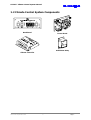
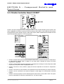
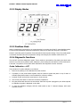
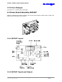
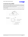
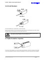
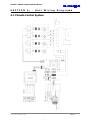
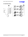
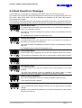
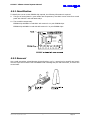
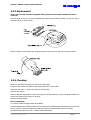
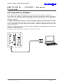
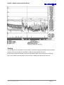
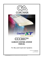
COACHAIR
CCC007*
CLIMATE CONTROL SYSTEM
MANUAL
For Bus and Coach A/C Systems
Document Number: SM423-3283
Revision No.: A
Issue Date: Sep 2006
Uncontrolled Copy: Please refer to the Network for the current issue of this manual
CCC007* Climate Control System Manual
Rev
Date
Description
00
Mar 25, 2002
First Release (Manual No SSMA001)
A
Sep 19, 2006
Update - CR 12098
Revise Layout, update pictures and review information
Section 5.4 Revise Error Message Descriptions
Released by S. Morley 20/09/06
Document Number: SM423-3283
Issue Date: September 2006
Uncontrolled Copy: Please refer to the Network for the current issue of this manual
Page 2
CCC007* Climate Control System Manual
NOTICE
The information in this manual is subject to change without notice.
Air International Transit shall not be liable for technical or editorial errors
or omissions contained herein.
No part of this manual may be photocopied or reproduced in any form
without prior consent from Air International Transit.
COACHAIR
CUSTOMER SUPPORT INQUIRIES
Australia
Malaysia
China
Telephone:
+61 2 9830 7132
+60 3 61208760
+86 519 5125568
Facsimile:
+61 2 9672 1082
+60 3 61208712
+86 519 5113086
Address:
3 Distillers Place
Lot No. 9, Jalan Empat,
Huntingwood 2148
Kawasan Perindustrian
Australia
Selayang, Off Jalan Besar,
Bandar Selayang,
68100 Selangor D.E. Malaysia
No. 268 West Hehai Road
Xinbei District,
Changzhou City
Jiangsu Province - P. R.
China 213000
WEB - www.aitransit.com
Document Number: SM423-3283
Issue Date: September 2006
Uncontrolled Copy: Please refer to the Network for the current issue of this manual
Page 3
CCC007* Climate Control System Manual
IMPORTANT INFORMATION
Beware of Automatic Operation When Working On The A/C Unit!
WARNING
Coachair’s electronic climate controller is programmed with a ‘leak stopper’ function. When the
bus engine is started the Coachair unit will start automatically after a three minute delay and
run for 90 seconds before stopping.
Before performing any service procedures make sure that the ignition isolating switch on the
unit control panel is set to OFF.
Handle Electronics With Care!
WARNING
Do not attempt to remove, repair, or handle the climate control panel or any components in any
way without referring to the correct procedures. The electrical control panel houses sensitive
equipment that may be damaged if handled incorrectly.
Refer to this CCC007* Climate Control System Manual for electronics service details before
attempting any diagnosis or repair.
*
NOTE
EPROM Version 2 ONLY!
The information in this book ONLY applies to CCC007* controllers with EPROM Version 2 or
later, with ESP1090 Power Board and Solid State Relays on the control panel.
Temperature Probes
Each temperature probe in the unit is factory calibrated. Use Probes as they have been
allocated.
CAUTION
DO NOT swap or mix the probes, as this may lead to unit damage and faulting.
24V DC ONLY
CAUTION
This unit is designed for a 24V DC electrical circuit ONLY. Do not under any circumstances use
another voltage, as this may cause unit damage and faulting.
There is power to the motors all the time. Never attempt to do repairs on motors or motor
wiring without manually breaking the correct circuit breaker first.
WARNING
CAUTION
Black Heat Sink
The black heat sink built onto the ESP109* PCB is at earth potential. DO NOT, under any
circumstances, place an earth or a bridge circuit on the heat sink, as this will cause serious unit
damage.
DO NOT use a test light. Use a suitable multimeter only!
CAUTION
DO NOT push the red reset button for more than 2 seconds, as this could provide unintentional
access to the CCC007* memory settings.
CAUTION
Document Number: SM423-3283
Issue Date: September 2006
Uncontrolled Copy: Please refer to the Network for the current issue of this manual
Page 4
CCC007* Climate Control System Manual
CONTENTS
SECTION 1: - General ........................................................................ 6
1.1 Introduction.......................................................................................................6
1.2 Climate Control System Components ...................................................................7
SECTION 2: - Operation ..................................................................... 8
2.1 Control Logic......................................................................................................8
SECTION 3: - Component Details and Functions................................. 12
3.1 Climate Controller Board CCC007*.....................................................................12
3.2 Temperature Probes.........................................................................................14
3.3 Dash Control Panel...........................................................................................15
3.4 Power Board Assembly ESP109* .......................................................................19
3.5 Solid State Relay ERR060..................................................................................22
3.6 Circuit Breakers................................................................................................24
3.7 Spike Protection Capacitor ................................................................................24
SECTION 4: - Unit Wiring Diagrams .................................................. 25
4.1 Climate Control System ....................................................................................25
4.2 Solid State Relay ..............................................................................................26
SECTION 5: - Maintenance and Service ............................................. 27
5.1 CCC Service Tools ............................................................................................27
5.2 Recommended Spare Parts ...............................................................................27
5.3 Parts Identification ...........................................................................................28
5.4 Dash Panel Error Messages ...............................................................................30
5.5 EPROM Replacement ........................................................................................31
5.6 Trouble Shooting..............................................................................................34
SECTION 6: - CCC007* Service Program............................................ 38
6.1 Connection to CCC007* ....................................................................................38
6.2 PC Communication ...........................................................................................39
6.3 Data Logger.....................................................................................................40
Document Number: SM423-3283
Issue Date: September 2006
Uncontrolled Copy: Please refer to the Network for the current issue of this manual
Page 5
CCC007* Climate Control System Manual
SECTION
1:
-
General
1.1 Introduction
Coachair climate controller CCC007* is an advanced control system tool used to drive the Coachair bus
and coach air conditioning units. The built-in microprocessor controls the operation of the total unit with
reference to the dash panel settings and operating conditions.
The climate control system accepts many inputs and provides many outputs to control the system.
Air Conditioning System Inputs and Outputs
The functions of the climate controller system include:
• Monitoring of return, ambient and supply air and two evaporator coil temperatures;
• Monitoring of the discharge and suction pressures;
• Acceptance of instructions from drivers dash panel;
• Communication with an external computer via a serial link;
• Intelligent control decision making;
• Display of return air and set point temperatures on the dash panel;
• Display of cooling - heating and fault conditions on dash panel;
• Display of diagnostic information on climate controller;
• Control of the operation of compressor clutch and unloader(s), evaporator and condenser motors,
water modulating valve and boost pump, fresh air actuator.
The climate control system consists of:
• Microprocessor logic controller.
• Temperature sensors.
• Digital dash panel.
• Dash panel communication harness.
• Power board.
• Solid state relays.
• Manual break - manual reset circuit breakers.
• Pressure switches (transducer).
• Spike protection capacitor.
• Wiring harness.
Document Number: SM423-3283
Issue Date: September 2006
Uncontrolled Copy: Please refer to the Network for the current issue of this manual
Page 6
CCC007* Climate Control System Manual
1.2 Climate Control System Components
Dash Panel
Power Board
Solid State Relay
Climate Controller
Document Number: SM423-3283
Issue Date: September 2006
Uncontrolled Copy: Please refer to the Network for the current issue of this manual
Page 7
CCC007* Climate Control System Manual
SECTION
2:
-
Operation
2.1 Control Logic
1.
Ignition feed from the bus/coach engine controls the operation of the climate control system. If there
is no ignition feed or the ON/OFF switch on the control panel in the unit is OFF, the system will not
operate.
2.
The climate controller will initialise when there is power from ignition and ON/OFF switch to terminal
2 on the power board. Climate controller will energise the main relay on the power board after a 7
second delay, and then look for further instructions.
3.
Main relay provides power for clutch, unloader(s), fresh air actuator and water modulating valve
circuits. It also supplies the feed for condenser motor control circuit.
Note: If main relay is faulty or removed there will not be refrigeration (A/C), but
evaporator blower operation will be available.
4.
If a dash panel is connected and its mode is OFF or FANS, a leak-stopper action will begin after a 3
minute delay. After the 3 minute delay the clutch will power (evaporator fans on low speed if the
mode is OFF, and condenser fans on) for 90 seconds. During the 3 minute delay the DE-ICE light will
flash once per second. If the dash mode is changed to A/C at any time the leaks-topper action is
cancelled and A/C will operate normally.
5.
The system is controlled via the dash panel:
• The mode of the system can be set (FANS - OFF - A/C switch).
• The evaporator fan speed can be selected (Decrease-Auto-Increase switch).
• The climate control (set point) temperature can be set (spring return rocker switch).
6.
The FANS setting of main switch provides evaporator blowers only at the selected fan speed. A/C
setting provides for operation of full climate control capability as dictated by the ambient conditions
and dash panel settings.
7.
Adjusting the Evaporator Fan Speed switch changes the evaporator fan speed when the mode is set
to FANS or A/C, unless this is overridden by another condition such as DE-ICE fault.
Decrease will reduce the fan speed of the evaporator blowers to approximately 60% of maximum
speed.
Increase will raise the fan speed of the evaporator blowers to maximum (100%).
AUTO setting will automatically and infinitely adjust the operating speed in relation to actual return
air and set point temperatures anywhere in between 60% to 100%. It will follow cooling only or
cooling and heating curves as decided by the microprocessor.
8.
The cooling-only and cooling-and heating curves used by CCC007* to determine the AUTO fan speed
are as follows:
Document Number: SM423-3283
Issue Date: September 2006
Uncontrolled Copy: Please refer to the Network for the current issue of this manual
Page 8
CCC007* Climate Control System Manual
9.
The temperature readout displayed on the dash panel can show either the actual return air
temperature or the set point temperature in degrees Celsius (°C).
The set point temperature can be adjusted to a warmer or cooler setting by pushing the spring return
rocker switch on the right hand side of the dash panel to WARM or COOL.
Briefly pressing and releasing switch to WARM or COOL will change the display from return air
temperature to the current set point.
Holding the switch on WARM or COOL will increase or decrease the set point in 0.5°C steps. When
the switch is released, the display will show the set point for another 10 seconds, and then revert to
displaying the return air temperature.
Note: The temperature setting is limited to between 18°C and 27°C.
10. CCC007* will operate the system in either cooling-only or cooling-and-heating mode. The mode to be
used is determined from a relation between the ambient and set point temperatures. The system will
be cooling-only when the ambient temperature is equal to or greater than set point + 6°C. There is a
+2°C differential on this cooling-only to cool-and-heat operation change point.
11. The position of the fresh air door is determined by the ambient temperature. CCC007* will open the
fresh air door via the actuator when the ambient temperature is between 18°C and 28°C. When the
temperature is outside the 18-28°C range, CCC007* will close the door. This automatic fresh air door
operation works independently and is not affected by the unit operating mode.
12. The following chart shows the temperature and capacity control logic for cooling only operation.
13. When the system operation is cooling and heating, the water modulation valve will be activated
through a P.I.D. routine around the set point temperature. The water modulation valve will open or
close to provide a calculated amount of hot water to the heating coils. The amount of heat to be
added is calculated continuously with reference to the set point, ambient, return air and supply air
temperatures. P.I.D. control responds very rapidly to changes and will keep the return air within
0.2°C of set point.
14. The yellow LED on the dash panel and the yellow LED marked WV on the climate controller flash to
indicate heating.
Document Number: SM423-3283
Issue Date: September 2006
Uncontrolled Copy: Please refer to the Network for the current issue of this manual
Page 9
CCC007* Climate Control System Manual
15. The compressor will be unloaded during the cooling-and heating mode. Heating is determined by the
P.I.D. routines, and there is no definite cut-in or cut-out point. Operation is primarily determined by
experience.
16. The boost pump is turned on whenever there is more than 2% water modulation and stays on for
another 60 seconds after the last modulation.
17. Each time the compressor clutch is energised, the green light on the dash panel and clutch light on
the climate controller illuminate.
When the clutch is de-energised, the control system will not allow the clutch to be re-energised
during the next 10 seconds.
The following conditions prevent the clutch from powering:
•
•
•
•
•
•
HP-LP open circuit or latched.
De-ice fault or latched de-ice.
Under voltage condition (Er5).
Return air < set point for clutch offset.
Faulty dash panel.
Blown fuse, faulty harness, faulty relay, bad connection, faulty clutch, etc.
18. A HP-LP fault will always override any function and turn the clutch off. The HP-LP switches are wired
in series and are normally in the closed position. When either of the switches open, CCC007*
deactivates the clutch until the circuit is closed again. The FLT LED on the controller and the red Fault
LED on the dash panel will light up.
If a HP-LP fault occurs 6 times in 30 minute period a latched fault will occur and an Er1 message will
display on the dash panel. The fault lights on the controller and the dash panel will flash.
19. A DE-ICE fault will always override any other function. Should the evaporator coil temperature drop
too low ice may form. When the evaporator coil (de-ice) temperature sensors detect an abnormally
low evaporator coil temperature initially the unloader(s) will be activated. If the condition continues
the clutch will be disengaged until the temperature rises.
If a de-ice fault occurs more than 6 times in 30 minutes a latched fault will occur, and the
compressor clutch will be permanently disabled to avoid damage. Er2 will display on the dash panel.
The fault lights on the controller and the dash panel will be on.
20. A latched fault is reset by removing the ignition feed to terminal 2 on power board or pushing the red
reset button on the climate controller. The reset switch is used to perform the following functions:
•
•
•
•
Cancel a latch fault condition.
Allow reading of all probe temperatures on the dash.
Allow setting of the evaporator fan PWM frequency.
Allow calibration of probes.
21. Whenever the compressor clutch is energised the condenser fans are activated. Condenser fans run
at HIGH speed in systems without mid-pressure switches. Condenser fans run at LOW, MEDIUM or
HIGH speed in systems with mid pressure switches. The pressure switch contact, open or closed,
determines the fan speed.
Clutch deactivation due to setting the dash mode switch to OFF causes condenser fans to stop
immediately, unless the unit is performing the leak stopper mode. Clutch deactivation due to ignition
being turned OFF causes condenser fans to stop immediately. When the clutch is deactivated by CCC
due to any other reason the condenser fans will run for a further 60 seconds and then stop.
22. Pressure Switches.
The MP1 pressure switch is a normally closed circuit type switch with the controlling pressures set as
follows:
Document Number: SM423-3283
Issue Date: September 2006
Uncontrolled Copy: Please refer to the Network for the current issue of this manual
Page 10
CCC007* Climate Control System Manual
140 psi
cut-in
condenser fan speed from high to medium.
190 psi
cut-out condenser fan speed from medium to high.
The MP2 pressure switch is also a normally closed circuit type switch with the controlling pressures
set as follows:
100 psi
cut-in
condenser fan speed from medium to low.
150 psi
cut-out condenser fan speed from low to medium.
MP1
MP2
CONDENSER FAN SPEED
Open
Open
High
Closed
Open
Medium
Open or Closed
Closed
Low
23. The clutch voltage is monitored at the clutch output pin to detect non-requested clutch powering.
Clutch voltage is checked when the system powers up, and also 2 seconds after every clutch power
removal. If the voltage is more than 14 V a latched Er3 will occur and the main relay will disengage.
This will remove power from the clutch output pin provided the main relay is not faulty or bypassed.
24. The system input voltage is monitored to a resolution of 0.1V and an accuracy of 2 V.
25. If the voltage falls below 20 V for a 27 V system, the clutch and condenser fans are turned off. If the
voltage falls below 18 V the evaporator fans are turned off.
If these errors occur more than 5 times this will result in a latched Er5.
26. A powered unloader output will result in an unloaded compressor. The unloader outputs always
switch on 1 second before the clutch, to ensure the compressor is unloaded for starting. The
unloader outputs normally remain powered when the clutch is off.
27. The fresh air output controls a relay which opens and closes an electric fresh air ram. Output is on
between 21°C and 26°C. Output is off below 17°C and above 29°C. This hysteresis is used to stop
the ram opening and closing when the ambient temperature is near to the trigger points.
Document Number: SM423-3283
Issue Date: September 2006
Uncontrolled Copy: Please refer to the Network for the current issue of this manual
Page 11
CCC007* Climate Control System Manual
SECTION 3:
Functions
-
Component
Details
and
3.1 Climate Controller Board CCC007*
CCC007* has been designed to be the intelligent “brain” of the Coachair Climate Control system. This
brain is adaptable to cooling-only and cool-and-heat systems and is able to control different size systems
through different power boards. CCC007* takes many inputs, makes sensible decisions based on these
inputs and generates outputs to control the process.
• CCC007* reads the dash panel switches, accepts the instructions, and makes decisions on what actions
to take.CCC007* decides what to display on the dash panel. Normally the Return Air Probe
temperature is displayed.
• CCC007* will also display set point temperature, all temperature readings, Er codes, Evaporator PWM
frequencies, and probe offsets at appropriate times.
• CCC007* connects to return, ambient, supply air and two evaporator coil sensors for temperature
sensing.
• CCC007* connects to a power board for the operational control and monitoring of various functions.
• CCC007* can be connected to an external computer or data logger for communication and data
logging.
• CCC007* receives its power from the attached power board via the 20-way ribbon cable. The power
board is responsible for delivering a regulated 8V or 12V power supply.
Document Number: SM423-3283
Issue Date: September 2006
Uncontrolled Copy: Please refer to the Network for the current issue of this manual
Page 12
CCC007* Climate Control System Manual
• When CCC007* is powered (normally due to application of IGN on power board) it performs a self
check. If the self check shows that the EPROM is damaged, it will issue an Er7 to the dash panel and
will load the default factory values as the operating variables.
• The probes will have no offset added to them.
• The reset button is for clearing a latched fault condition. It also provides sequential entry code to the
system for higher order data transfer such as temperature calibration, reading of temperatures, etc.
• The seven LED’s on the climate controller will always indicate the operating mode of the system and is
indeed a very useful tool for trouble shooting.
Display
Description
Message
IGN
Ignition
This green LED will light when CCC007* is powered by ignition feed to
terminal 2 on the power board.
FLT
Fault
This red LED will:
• Light when there is a HP or LP fault.
• Flash when there is a latched fault.
ICE
Defrost
This red LED will:
• Light when there is a de-ice condition: de-ice probe is below 2°C or
above 80°C (open circuit).
• Flash when there is latched de-ice condition.
• Flash at a slower rate when the system is in stop leak delay counting
mode.
• Flash when CCC007* is sending data to a computer or data logger.
UN2
Unloader 2
This yellow LED indicates the system is unloaded and the unloader from
terminal 28 is energised. (The first one to unload in cooling down logic).
UN1/CL2
Unloader 1
This yellow LED indicates the system is unloaded and the unloader from
terminal 29 is energised. (The second one to unload in cooling down logic,
unloader for 4 cylinder compressor or second compressor clutch for twin
compressor models).
CL
Clutch
This green LED will illuminate whenever clutch relay is energised.
WV
Water Valve
This yellow LED will be energised whenever the water valve is being
modulated. The rate of flashing will depend on the amount of modulation
calculated.
Note: CL, UN1, UN2 LED’s may glow dull when main relay is off, even though the
individual relays are not on.
Document Number: SM423-3283
Issue Date: September 2006
Uncontrolled Copy: Please refer to the Network for the current issue of this manual
Page 13
CCC007* Climate Control System Manual
3.2 Temperature Probes
Coachair Climate Controllers currently use solid state temperature sensors. There is a miniature integrated
circuit at the tip of every probe.
The temperature sensors are fast acting integrated circuit type with a very linear and stable output.
Although the probes are replaceable, they are not interchangeable within the system or replaceable
without a reliable calibration.
The minimum temperature that can be read is -20°C and the maximum is 82°C. The probes are read in
0.1°C steps.
3.2.1 Return Air Probe
Return air temperature probe senses the returning air temperature to the unit. Return air temperature is
used to control the cooling capacity and in a sense heating capacity in reference to set point value.
An open-circuit return air probe will cause maximum cooling. The dash panel will display a temperature
between 80°C - 85°C indicating an open circuit probe.
A short-circuit return air probe would cause maximum heating, unless the heating was disabled by high
ambient. The dash panel will display 10.
3.2.2 Evaporator Coil (De-Ice) Probe
The evaporator coil probes are inserted into the fins of evaporator coils. They sense the actual coil
temperature. The de-ice probes are housed in special probe holders that provide strength and better
contact with coil fins.
As a safety feature, a short circuited or open circuited de-ice probe will cause a permanent de-ice
(defrost) condition.
3.2.3 Air-Off Probe
The air off probe is located after the evaporator and heater coils. It senses the temperature of supply air
to the bus cabin interior. The air off probe is only used in cooling and heating units, and functions as a
secondary control for perfect temperature stabilisation during heating mode.
An open circuited air off probe will cause permanent disabling of the heating function while a short
circuited air off probe will cause maximum heating when the unit is in heating mode.
3.2.4 Ambient Probe
The ambient air probe is used on cooling-and-heating units and cooling-only units with automatic fresh air
operation. It senses the air temperature outside the bus. This temperature input determines whether the
operation mode is cooling-only or cooling-and-heating, and whether fresh air is introduced to the system.
An open circuited ambient probe will permanently disable the heating and fresh air operation where as a
short circuited ambient probe will run the unit on cooling and heating mode all the time with no fresh air.
Document Number: SM423-3283
Issue Date: September 2006
Uncontrolled Copy: Please refer to the Network for the current issue of this manual
Page 14
CCC007* Climate Control System Manual
3.2.5 Probe Calibration
Probes cannot be accurately calibrated in still or moving air due to the potential influence of radiated heat
sources. Probes are ideally calibrated in an insulated and stirred water bath in an air-conditioned room.
Probes are typically within 1.5°C without calibration.
3.3 Dash Control Panel
The dash panel is the user's control device. It gives feedback to the user and allows them to control some
aspects of the system.
The dash panel has no “intelligence” and makes no decisions. Its operation is confined to multiplexing
LED’s and communicating with CCC007*. The dash panel communicates to CCC007* the position of its
switch settings, and CCC007* instructs the dash panel on what LED’s to light and what numbers to
display.
If the dash panel does not receive valid data within 1 second, it displays three dashes. If CCC007* does
not receive valid data within 6 seconds the system switches to dashless mode of operation.
3.3.1 Dash Controls Details (EAD1730)
The FAN-OFF-A/C and LOW-HIGH switches and the WARM-COOL temperature rocker potentiometer on
the dash panel are the only three external controls to operate the system.
FAN-OFF-A/C switch positions (3 position)
FAN
- Evaporator blowers are on.
- Air conditioning is off.
- Dash temperature display and set point is on.
OFF
- Air conditioning system is off.
- Dash temperature display and set point is on.
A/C
- Air conditioning system is on.
- Dash temperature display and set point is on.
Document Number: SM423-3283
Issue Date: September 2006
Uncontrolled Copy: Please refer to the Network for the current issue of this manual
Page 15
CCC007* Climate Control System Manual
LOW-AUTO-HIGH switch positions (3 position)
(Functional only if FAN-OFF-A/C switch is in FAN or A/C positions)
LOW
- Evaporator blowers are on low speed, 60%.
AUTO - Evaporator blowers are on variable speed, 60% to 100%.
HIGH - Evaporator blowers are on high speed, 100%.
WARM-COOL rocker potentiometer function
(Functional if ignition is activated)
WARM - Increases the set point temperature in 0.5°C intervals when held.
COOL - Decreases the set point temperature in 0.5°C intervals when held.
Pressing the switch on either WARM or COOL momentarily will cause the temperature set point for 30
seconds only. The display will then revert to the default return air temperature display.
Document Number: SM423-3283
Issue Date: September 2006
Uncontrolled Copy: Please refer to the Network for the current issue of this manual
Page 16
CCC007* Climate Control System Manual
3.3.2 Display Modes
3.3.3 Dashless Mode
When no dash panel is connected, or no communication is occurring, the CCC007* enters dashless mode.
It uses the last saved dash mode and temperature setting as its mode and set point of operation.
CCC007* saves the mode of operation 5 seconds after the last set point change. Thus, if the mode switch
on the dash was OFF when the temperature setting was changed, the dashless mode will be off.
3.3.4 Diagnostic Functions
The CCC007* has three diagnostic modes. These modes are accessed by first placing the dash mode
switch in one of the three positions (OFF, FANS, A/C), then holding the reset button on the CCC down for
8 seconds. The position of the mode switch determines the diagnostic function accessed.
Probe Calibration = OFF
The procedure for probe calibration is as follows:
1.
Remove the probe(s) to be calibrated from their sockets.
2.
If possible, tie the probe heads together with the reference probe and place in cup of water. A
scientific glass thermometer is recommended for reference reading.
3.
Put dash to OFF and hold the reset button in for 8 seconds.
4.
Use the set point switch to select the reference temperature.
5.
Plug the probes back into their correct sockets. Each time a probe is plugged in, the offset required
to calibrate the probe is displayed on the dash.
6.
To save the calibration changes, shift the mode switch to A/C. To discard changes, shift mode
switches to Fans.
Document Number: SM423-3283
Issue Date: September 2006
Uncontrolled Copy: Please refer to the Network for the current issue of this manual
Page 17
CCC007* Climate Control System Manual
Evaporator Fan Frequency Settings = FANS
This feature is used to overcoming chassis resonance problems. Changing the frequency to an antiresonant point should make evaporator fan motor pulsing indiscernible at low speed. It does not cause
any change in high speed.
The frequency of the pulsing of the evaporator motors can be changed by:1.
Set dash mode to FANS and fan speed to LOW and push reset switch in until you hear fans go to
high speed
2.
Use the set point switch to alter frequency. (limits are 1.0-2.2)
3.
Save change by moving dash switch to OFF.
The actual frequency can be calculated by dividing 50 with the dash number:
e.g.
50/1.2= 41.6Hz
50/2.2= 22.7Hz
Calculate the new frequency and record it on the commissioning sheet.
Display of Sensor Readings = A/C
The display of each probe temperature is a handy field service feature.
1.
Set the dash mode to A/C and hold the Reset button in for 8 seconds.
2.
The dash will display all 5 probes in sequence until the dash mode switch is returned to OFF. The A/C
system operates normally while this is occurring
Document Number: SM423-3283
Issue Date: September 2006
Uncontrolled Copy: Please refer to the Network for the current issue of this manual
Page 18
CCC007* Climate Control System Manual
3.3.5 Error Messages
See Section 5.4 - Dash Panel Error Messages
3.4 Power Board Assembly ESP109*
ESP109* is designed to connect to CCC007* and convert signal outputs to higher power outputs, and
gather inputs to feed back to the CCC007*.
3.4.1 ESP109* Layout
3.4.2 ESP109* Inputs and Outputs
Document Number: SM423-3283
Issue Date: September 2006
Uncontrolled Copy: Please refer to the Network for the current issue of this manual
Page 19
CCC007* Climate Control System Manual
INPUTS
Power Input (PWR)
Power (Vbatt) is connected via a 15A circuit breaker. Chassis ground is also connected.
Ignition Input (IGN)
Ignition input powers a small relay coil via a diode. The contact of this relay supplies power from the PWR
input to the +12V regulated power supply circuit.
ESP189* units use a 12V coil relay.
High Pressure Low Pressure Input (HP-LP)
Pin 13 is connected directly to ground.
Pin 15 will normally read 5 V when nothing is connected, and when either switch is open (a fault
condition).
When both switches close Pin 15 will read 0V.
Mid Pressure 1 Input (MP1)
The MP1 input is 5V when the pressure switch is open circuited.
Grounding this input will cause the condenser motors to modulate when the compressor is on (normally
via a pressure switch which opens as pressure rises).
Mid Pressure 2 Input (MP2)
The MP2 input is 5 V when the pressure switch is open circuited.
MP2 input could connect to a linear pressure transducer, which all Version 2 CCC007*s can recognise. This
would allow actual system pressure to be read. Thus, condenser fan RPM could be varied with system
pressure, modulating from 0 to 100%.
Document Number: SM423-3283
Issue Date: September 2006
Uncontrolled Copy: Please refer to the Network for the current issue of this manual
Page 20
CCC007* Climate Control System Manual
OUTPUTS
Evaporator Motor Trigger Output (EV1 and EV2)
These are low current outputs designed to power the solid state relay trigger inputs.
Condenser Motor Trigger Output (CM1 and CM2)
These are low current outputs designed to power the solid state relays trigger outputs. They are protected
against shorting to ground or Vbatt.
Clutch Output
The pin 31 is powered via the clutch relay through its 7.5A fuse and via the main relay.
A reversed biased diode is on the output to quench inductive flyback from the clutch coil.
Unloader Output
The unloaders share their own 7.5A fuse.
An unloader output must be powered to unload the compressor. The controller will always attempt to
unload a compressor before engaging the clutch to reduce start torque on the clutch.
Fresh Air Output
The fresh air ram shares the same output plug with the water modulation valve.
Power is available to the fresh air output as soon as the main relay is engaged.
Because the fresh air output is designed to run a motor bi-directionally, power and ground reverse on pins
34/35 when the relay engages.
Water Modulation Valve Output
The top left pin of the modulation valve connects directly to a 3A fuse.
The bottom left pin is switched to ground by the mosfet.
Grounding the bottom left pin will cause the modulator valve to stay on 100%.
The mosfet is either on or off. The frequency is high enough that measuring across the output pins will
give an average voltage reading.
Boost Pump Output
The comments apply as were discussed with the Clutch output, except this output is not monitored by the
CCC007* controller.
D2 is the inductive suppression diode for this output.
Document Number: SM423-3283
Issue Date: September 2006
Uncontrolled Copy: Please refer to the Network for the current issue of this manual
Page 21
CCC007* Climate Control System Manual
3.5 Solid State Relay ERR060
The Coachair solid state relay is designed to be used in ground switching inductive and resistive loads. It
combines the features of conventional solid state relays and circuit breakers for 24 V DC applications.
Coachair solid state relays are rated for 25A continuous loading at 27 V DC and employ solid state
electronic device technology eliminating contact wear and fusing.
They are protected against water and dust and because there are no moving parts they are highly shock
and vibration resistant.
They could be switched up to 10 kHz frequency for resistive and 1 kHz for inductive loads. Switching time
is around 10 - 30 milliseconds making it quite reliable in case of short circuits. Trigger current is 3mA.
Document Number: SM423-3283
Issue Date: September 2006
Uncontrolled Copy: Please refer to the Network for the current issue of this manual
Page 22
CCC007* Climate Control System Manual
SOLID STATE RELAY TECHNICAL SPECIFICATIONS
Operating Voltage
12-30 V DC
(Battery voltage must never exceed 45 V)
Trigger Voltage
6 V DC
Min 2 V, Max 50 V
Trigger Current
1mA per 10 V load voltage
Rating Free Air
20A continuous
Rating 5°C/W Heat Sink
30A
ON Resistance
10 milliseconds @ 25°C
Fault Trip Current
Approximately 140A
(auto reset in 3 seconds)
Over Current Trip Time
< 10 milliseconds
Temperature Cut-out
85°C-105°C (auto reset after cooling 20°C)
Switching Time
2 milliseconds
Max Switching Frequency
10 kHz for resistive loads. 1 kHz inductive loads
(depends upon inductance)
The green LED indicates relay switching as normal operation, red LED indicates a short on the load circuit
and relay not switching as a result, and the yellow LED indicates that the relay is overheating due to
overloading.
Coachair solid state relays are used in ground switching of evaporator and condenser motors at frequency
decided by the climate controller. Under no condition, can they be used to switch power to the motors.
The relay case is earth connection.
Back EMF from each motor is suppressed internally by each solid state relay. If motor + is not connected,
the relay will operate but there could be damage to relay, motor and microprocessor as a result.
Document Number: SM423-3283
Issue Date: September 2006
Uncontrolled Copy: Please refer to the Network for the current issue of this manual
Page 23
CCC007* Climate Control System Manual
3.6 Circuit Breakers
The circuit breakers are a manual break - manual reset type.
When the circuit breaker is in the normal online, position push in the reset button until a click is heard,
the button will pop out and power to the rest of the circuit is cut.
There is power to the motors all the time. Never attempt to do repairs on motors or motor
wiring without manually breaking the correct circuit breaker first.
WARNING
3.7 Spike Protection Capacitor
The function of this capacitor is to overcome battery cable inductance. When the solid state relays switch
off, the internal diode will be able to dump the back EMF from the motors inductance into the capacitor.
Document Number: SM423-3283
Issue Date: September 2006
Uncontrolled Copy: Please refer to the Network for the current issue of this manual
Page 24
CCC007* Climate Control System Manual
SECTION
4:
-
Unit
Wiring
Diagrams
4.1 Climate Control System
Document Number: SM423-3283
Issue Date: September 2006
Uncontrolled Copy: Please refer to the Network for the current issue of this manual
Page 25
CCC007* Climate Control System Manual
4.2 Solid State Relay
Document Number: SM423-3283
Issue Date: September 2006
Uncontrolled Copy: Please refer to the Network for the current issue of this manual
Page 26
CCC007* Climate Control System Manual
SECTION
5:
-
Maintenance
and
Service
5.1 CCC Service Tools
• Multimeter.
• Wrist Strap.
• Scientific Thermometer.
• 1m Dash Cable.
• Dash Panel EAD1730.
• Crimping Tools and Terminals.
• Dash Cable Tester.
• Service Manual.
• Anti-static Mat.
• Anti-static Bags.
5.2 Recommended Spare Parts
• Circuit Breakers.
• Solid state relays.
• Fuses.
• Temperature sensors.
• EPROM’s.
• CCC007*.
• ESP109*.
• 1A Slow Blow Fuse.
Document Number: SM423-3283
Issue Date: September 2006
Uncontrolled Copy: Please refer to the Network for the current issue of this manual
Page 27
CCC007* Climate Control System Manual
5.3 Parts Identification
5.3.1 CCC007* Climate Controller
PART NUMBER
DESCRIPTION
REVISION NUMBER
CCC0074
Controller for Brushed Motors (24V)
2.26c
CCC0075
Controller for Brushed Motors (12V)
2.26c
CCC0077
Controller for Twin Compressors (24V)
5.60
CCC0078
Controller for Brushless Motors (24V)
2.28
Note: Sensors are not included with the climate controller, and must be purchased
separately. New sensors must be calibrated when they are installed.
5.3.2 ESP109* Power Boards
PART NUMBER
DESCRIPTION
ESP1890
12V version
ESP1090
24V version
ESP209
Twin Compressor Unit
Note: Power boards do not come complete with fuses nor automotive type mini relays
Fuses and mini relays are purchased separately.
5.3.3 Temperature Sensors
RETURN AIR SENSORS
PART NUMBER
LENGTH (mm)
ERP030
550
ERP031
1,500
ERP032
2,500
DE-ICE SENSORS
PART NUMBER
LENGTH (mm)
ESP030
550
ESP031
1,500
Document Number: SM423-3283
Issue Date: September 2006
Uncontrolled Copy: Please refer to the Network for the current issue of this manual
Page 28
CCC007* Climate Control System Manual
5.3.4 Solid State Relays
PART NUMBER
DESCRIPTION
ERR060(0)
Standard SSR for Brushed Motors (25A).
5.3.5 Circuit Breakers
PART NUMBER
DESCRIPTION
ERC015
Circuit Breaker 15A Manual Break & Reset
ERC016
Circuit Breaker 10A Manual Break & Reset
5.3.6 Dash Control Panels
EAD173
Document Number: SM423-3283
Issue Date: September 2006
EAD176
Uncontrolled Copy: Please refer to the Network for the current issue of this manual
Page 29
CCC007* Climate Control System Manual
5.4 Dash Panel Error Messages
The dash panel error messages are displayed when specific faults occur in the A/C system.
The climate control system incorporates self-diagnostic functions that can recognise specific faults in the
A/C system. When these faults occur Error Messages are displayed on the driver dash panel to
communicate the condition.
The illustrations on this page show the warning lights of the EAD176 dash panel. Other dash panels may
use warning lights instead of symbols. However, the fault LED may always be identified by its red colour.
Latched HP/LP Fault
The system has cut the clutch more than 6 times in 30 minutes due to detection of
high or low refrigerant pressure.
As a result the system has disabled A/C operation (clutch) to avoid damage. Red fault
light flashing.
Er1 message may be removed by resetting the unit.
Latched De-Ice Fault
The system has cut the clutch more than 6 times in 30 minutes due to detection of
abnormally low evaporator temperatures.
As a result the system has disabled A/C operation (clutch) to avoid damage. Red fault
light is on.
Er2 message may be removed by resetting the unit.
Frozen Clutch Relay
A frozen clutch relay is supplying power to the clutch without control of the system.
The controller has disabled the main relay to avoid damage. Red fault light is flashing.
There is no Er4 message.
Low Supply Voltage
The power supply to the A/C unit is below 18V DC (24V systems), or 8.5V (12V
systems).
The clutch and condenser motors are disabled at 20V power supply. If voltage
continues to drop error message is activated. Red fault light is flashing.
Sensor(s) Out of Calibration
One or more temperature sensors are outside acceptable calibration limits.
Those sensors should be replaced.
CCC007* EPROM Error
Custom programmed system settings have been lost. The system will use the default
settings.
Message may be removed by holding the control panel reset button for two seconds
when bus is turned on/
Document Number: SM423-3283
Issue Date: September 2006
Uncontrolled Copy: Please refer to the Network for the current issue of this manual
Page 30
CCC007* Climate Control System Manual
5.5 EPROM Replacement
CAUTION
Sensitive electronic Componentry
Static charges may cause serious damage to the controller. Always wear anti-static earthing trap
before touching controller.
The EPROM is a program chip located in the climate controller. The following steps explain the
identification, removal, replacement, and checking procedures for the correct EPROM replacement.
1.
BEFORE accessing the control panel, place the dash FANS-OFF-A/C switch in the off position.
2.
Place the ON-OFF toggle switch on the control panel to the OFF position. This turns off the ignition
feed to the system.
3.
Disconnect the PWR +/- plug from the ESP109* Power Board.
Note: To save confusion, before removal, identify the various probes and cables by
marking them with a colour or tag.
4.
Disconnect all the probes and cables connected to the CCC007* controller board.
5.
Disconnect the data cable plug from the CCC007* PCB socket.
6.
Remove the CCC007* from the control panel by undoing the 4 retaining screws.
Note: The spacers are separate, do not loose them.
7.
Connect an anti-static earthing strap to yourself and the bus frame.
8.
Undo the 4 retaining screws, on the reverse side of the PCB under the insulation, and remove the
protective black plastic cover.
Document Number: SM423-3283
Issue Date: September 2006
Uncontrolled Copy: Please refer to the Network for the current issue of this manual
Page 31
CCC007* Climate Control System Manual
5.5.1 Identification
To identify the correct version EPROM chip required, the following information is required:
9.
The type of control panel i.e. part number and componentry. Use ONLY Version 2.26c for a control
panel with CCC007* and solid state relays.
10. The controller componentry.
EEPROM chip 93C06B1 is used ONLY with version 2.4 or prior EPROM chips.
EEPROM chip 93C46B1 is used with ANY version 2.X or prior EPROM chips.
5.5.2 Removal
Use a small screwdriver, placed between chip and socket, or a I.C. removal tool to carefully and evenly
lever the chip from its socket. Take care not to bend or damage the pins and socket case, or remove the
version label.
Document Number: SM423-3283
Issue Date: September 2006
Uncontrolled Copy: Please refer to the Network for the current issue of this manual
Page 32
CCC007* Climate Control System Manual
5.5.3 Replacement
Note: The new chip should be supplied with a printed version label, which must not be
removed.
Carefully align all the pins of the new EPROM chip with the socket base, making sure that the chip is
correctly placed, as shown below.
Place the PCB on a flat surface and using light pressure push down on the chip until firmly seated.
5.5.4 Checking
Reconnect the Data cable plug to the CCC007* PCB socket.
Reconnect the probes and cables to the matching CCC007* PCB sockets.
Reconnect the PWR +/- plug to the ESP109* Power Board.
Start the bus engine.
Place the ON-OFF toggle switch on the control panel to the ON position, turning on the ignition feed to the
system (provided the bus engine is running).
Observe the dash display.
If Er7 is displayed:
Turn OFF the ON-OFF toggle switch immediately.
Push and hold down the RESET button while turning ON the ON-OFF toggle switch and observe the fault
light on CCC007*. When this light stops flashing, release the RESET button (within 1 second).
Re-calibrate the probes (see 3.2.5 - Section Probe Calibration).
Document Number: SM423-3283
Issue Date: September 2006
Uncontrolled Copy: Please refer to the Network for the current issue of this manual
Page 33
CCC007* Climate Control System Manual
If Er7 is not displayed and the dash shows a normal temperature:
There is no need to initialise and re-calibrate as the old settings have been accepted.
11. Place the ON-OFF toggle switch on the control panel to the OFF position.
12. Replace the protective black plastic cover, return the 4 retaining screws, on the reverse side of the
PCB under the insulation.
13. Return the CCC007* controller to the control panel making sure that the spacers are placed
underneath the PCB. Do not over tighten these screws as this may cause PCB damage.
14. Place the ON-OFF toggle switch on the control panel to the ON position and check that the unit is
functioning.
5.6 Trouble Shooting
5.6.1 Dash Panel is Displaying Erx
Er Message
Possible Causes
High pressure due to:
• Overcharge of refrigerant
• Blocked discharge line or faulty discharge service valve
• Insufficient condenser air flow due to:
Condenser motor(s) not running.
Condenser motor(s) running backwards.
Bent or broken condenser fan.
Blocked condenser coil (too much dirt or bent fins).
Faulty receiver (excessive charge required for A/C to cool).
Air present in system.
• Open circuit or intermittent wiring connection in pressure switch circuit.
Low pressure due to:
• Blocked (dirty) return air filter
• Insufficient refrigerant charge
• Possible gas leak:
Hoses and pipes
Flange seal
• Blocked liquid/suction line or faulty suction valve
• Blocked drier.
• Faulty TX valve.
• Insufficient evaporator airflow due to:
Evaporator motor(s) running backwards.
Bent or broken fan wheel.
Blocked evaporator coil (dirty).
Incorrect duct sizing and vent placement.
• Faulty pressure relief valve.
• High suction and low discharge pressure due to:
Compressor belt slipping from incorrect tension on adjuster
Compressor damaged/faulty
• Open circuit or intermittent wiring connection in pressure switch circuit.
• Dirty evaporator coils.
• Block return air filter.
• Faulty TX valve - poor evaporator refrigerant flow.
• Low airflow over evaporator coil due to supply air fan/motor failure.
Document Number: SM423-3283
Issue Date: September 2006
Uncontrolled Copy: Please refer to the Network for the current issue of this manual
Page 34
CCC007* Climate Control System Manual
• Electrical / Climate Control System
• Insufficient Capacity of bus alternator
• Loose power cable
• Loose earth cable
• Electrical / Climate Control System
• Electrical / Climate Control System
5.6.2 Dash panel is displaying “---“
Cause:
• Dash panel is not receiving error free communications due to faulty dash harness.
• Dash panel is not receiving error free communications due to or excessive electronic noise.
Remedy:
• Replace dash harness.
• Replace end plugs.
• Remove electronic noise.
• Check plugs are secure on cable from dash controller to climate controller.
5.6.3 Dash panel is displaying “lO” and unit is not cooling
Cause:
• Faulty return air probe (short circuit).
• Damaged EPROM.
Remedy:
• Remove return air probe. Dash should show 80+oC. Install a new return air probe and calibrate.
5.6.4 Dash panel is displaying “82” unit cooling at full capacity
Cause:
• Faulty return air probe (open circuit).
• Damaged EPROM.
Remedy:
• Install a new return air probe and calibrate.
Document Number: SM423-3283
Issue Date: September 2006
Uncontrolled Copy: Please refer to the Network for the current issue of this manual
Page 35
CCC007* Climate Control System Manual
5.6.5 Display is showing abnormal reading and is not steady
Cause:
• Communication between the dash and the climate controller is being interrupted by stray
electromagnetic frequency.
Remedy:
• Remove and replace harness with blue shielded harness that will be earthed at CCC007*.
• Ensure that the dash harness does not run with the power cables.
5.6.6 The dash set point display counts in unusual numbers
(e.g. 21.8, 22.3, 22.8, etc)
Cause:
• The program is still using the calibration set point.
Remedy:
• To restore the set point display to numbers that end in .0 and .5, adjust the set point to the upper or
lower limit (i.e. 18.0°C or 26.0°C).
5.6.7 Compressor is not unloading
Cause:
• Faulty unloader.
• Faulty unloader relay.
• Blown fuse.
• System is in cool-heat mode.
• Blown
Remedy:
• Check set point and ambient temperatures.
• Removing the ambient probe should return the system to cooling-only mode.
5.6.8 Heat light flashes when the system is cooling
Cause:
• This symptom should only occur in heat-cool mode. As the minimum Air-Off Required is set to 6°C,
CCC007* will inject a small amount of heat when the air temperature drops below 6°C, in order to
maintain that temperature.
5.6.9 The R/A temperature is different to displayed temperature
Cause:
• Probe calibration is incorrect.
Remedy:
• Check the temperature probe calibration, and recalibrate if necessary.
Document Number: SM423-3283
Issue Date: September 2006
Uncontrolled Copy: Please refer to the Network for the current issue of this manual
Page 36
CCC007* Climate Control System Manual
5.6.10 A/C is on, fans are running, but clutch is not engaging
Cause:
• HP-LP open circuit or latched.
• De-ice fault or latched.
• Under voltage condition (Er5).
• Return air is less than the set point.
• Faulty dash panel.
• Blown fuse, faulty harness, faulty relay, bad connection, faulty clutch etc.
5.6.11 Return air temperature is changing up and down
considerably
Cause:
• Confirm that there are no other faults in the system. Ambient temperature is changing considerably,
causing the system operating mode to change from cool-only to cool-heat or vice versa.
Note: Cool-only mode will cut cooling when the return air is 1oC below the set point
temperature.
• Cool-heat mode will keep the return air at the set point, but will overshoot set point by x°C at the very
beginning of the P.I.D. system.
Remedy:
• Change set point up or down by 1°C.
5.6.12 No heating
Cause:
• Ambient sensor is open circuit.
• Air off sensor is open circuit.
• Ambient sensor is out of calibration.
• Boost pump is not operating.
• Isolation valves closed.
Document Number: SM423-3283
Issue Date: September 2006
Uncontrolled Copy: Please refer to the Network for the current issue of this manual
Page 37
CCC007* Climate Control System Manual
SECTION
Program
6:
-
CCC007*
Service
6.1 Connection to CCC007*
The serial port is the window through which we can see what the microcontroller is “thinking”.
The CCC007* can connect to a personal computer to allow for sending and receiving information.
CCC007* can also be connected to the Data Logger, another Coachair device, for recording system
operating information.
To enable communication with CCC007*, a personal computer or laptop must be connected to the climate
controller via a serial data link. This link consists of a special modular cable with the correct plugs wired
up in a serial fashion. This cable plugs into the CCC007* controller's COM PORT and then into the
computer's serial port.
CCC007* can communicate with any computer capable of displaying and sending ASCII text at 9600 baud,
8 data bits, 1 Stop bit, No Parity.
A cable is required to adapt to the 4W4P RJ11 connector on CCC007*.
Document Number: SM423-3283
Issue Date: September 2006
Uncontrolled Copy: Please refer to the Network for the current issue of this manual
Page 38
CCC007* Climate Control System Manual
6.2 PC Communication
Once the correct connections have been made as detailed in section 6.1 communication can be
established with CCC007*.
6.2.1 Direct Commands
Communication is established with CCC007* in the same manner as a standard PC linkup. Once the
protocols have been established, commands can be typed in and CCC007* will respond.
There are many available commands for CCC007* communication. These commands can program
CCC007* operational parameters, and display recorded system information. The following table lists some
of these commands.
COMMAND
TYPE
MIN MAX
DEF
DD
C
Display Probe temps, bus volts and Status word in
one ASCII line
DV
C
Display CCC007 Snapshot
RAOS
RW
-127
127
0
°Cx10
Return Air Offset
EV1OS
RW
-127
127
0
°Cx10
Evaporator 1 Offset
EV2OS
RW
-127
127
0
°Cx10
Evaporator 2 Offset
AOOS
RW
-127
127
0
°Cx10
Air Off offset
AMBOS
RW
-127
127
0
°Cx10
Ambient offset
SPMIN
RW
0
255
180
°Cx10
Minimum set point from dash
SPMAX
RW
100
355
270
°Cx10
Maximum set point from dash
ONDEL
RW
0
600
120
Secs
Delay from Power up to 'Leak Stopper' A/C in
seconds.
SP
R/W
-20
80.0
°C
Set point will stay set until dash panel changes it.
HV
RW
0
100
pwm
Percent modulation (before linearization) of Heat.
VB
R
0
100
Volts
Battery Voltage
VC
R
0
100
Volts
Clutch Voltage
-
UNIT DESCRIPTION
Snapshot
A section in the CCC007* EEPROM memory is devoted to storing a “snapshot” of key system variables.
These variables can be accessed individually by using the appropriate commands. The snapshot variables
are as follows:
• Software version.
• CCC version.
• Total clutch hours.
• Total pump hours.
• Number of pressure switch faults.
• Number of de-ice faults.
• Number of system latched faults.
Document Number: SM423-3283
Issue Date: September 2006
Uncontrolled Copy: Please refer to the Network for the current issue of this manual
Page 39
CCC007* Climate Control System Manual
6.2.2 LOG007 Software
LOG007 (LOG007.EXE) is a program that is used when a PC is correctly linked to CCC007*, as detailed in
Section 6.1 - Connection to CCC007*.
The purpose of LOG007 is to continually log the operating variables of the climate control system. The
system variables are shown on the computer screen, and are continually updated after every sampling
interval. A typical sampling interval would be 1 minute.
When logging is finished the logged variables can be saved as a file for later examination and charting.
The variables logged include:
• Time.
• Set point temperature.
• Return air temperature.
• Evaporator coil probe temperatures (1 and 2).
• Air off temperature.
• Ambient temperature.
• Heat.
• Air off required.
• Bus voltage.
• Clutch status (on or off).
• Unloader 1 and 2 status (on or off).
The LOG007 software will be available on a single 3 1/4 computer disk (MS-DOS system only).
6.3 Data Logger
The Coachair CCC007* Data Logger is a self-contained microprocessor device which connects to the
CCC007* controller for continuous recording of system operating information. The purpose of recording
this information in the data logger is to aid system analysis and trouble shooting.
When the system is operating a connected data logger records a continuous log of the following
information:
• All temperature inputs (return air, evaporator coils, ambient, and air off);
• Supply voltage.
• Percent heat modulation.
• Air off required.
• Binary inputs (clutch, unloaders, HP-LP fault, fresh air flap, mid-pressure switches).
• Time and date of sample.
The data logger also has 6 external temperature probe inputs for recording other system parameters.
Once the data logger is removed from the bus it can be connected to a personal computer and the logged
information can be downloaded. The procedures and requirements for connecting the data logger to a
personal computer are the same as applies for CCC007* connection (described in Section 6.1 - Connection
to CCC007*). Special software is used for downloading to a PC.
Document Number: SM423-3283
Issue Date: September 2006
Uncontrolled Copy: Please refer to the Network for the current issue of this manual
Page 40
CCC007* Climate Control System Manual
6.3.1 Data Logger Software
The data can be downloaded to the computer via special Data Logger software program. Once it is
downloaded the information can be analysed. The data logger program (DL.EXE) presents the selected
information as a continuous graph for easy analysis.
The data logger software will be available on a single 3 1/4 computer disk (MS-DOS system only).
Data Downloading
The Data Logger program can be used to:
• Read and down load the data from the data logger to the PC
• When downloading, the program reads all the information stored in the data logger. When the
program finishes downloading the data traces are displayed on the screen.
• If there is no data in the data logger (erased or new logger) a message is displayed to indicate this.
• Erase the logger
• When erasing the logger the current date and time are read from the PC’s internal clock.
• The sampling rate may be set. Generally, a sampling rate of 10 seconds is preferred, but the
sampling rate can be set to 20, 30, or 60 seconds.
• Save and open the data results for viewing.
• The preferred file name format is XXXXMMDD.LOG, where XXXX is the logger ID number, and
MMDD is the month and the date logger has been returned. For example, if data logger number
1004 is returned from the field on 23rd of August, then the file name should be 10040823.LOG.
A HELP facility is also available that lists the keyboard commands used to operate the software features.
Viewing Data for Analysis
When a data logger file has been opened the computer screen displays the following information.
Data Traces
The data readings are displayed on a graph showing Temperature Reading VS Time.
The display of the data readings can be toggled between individual readings and continuous line graphs.
The exact values for all readings can be viewed at any chosen time point.
By default all data traces are shown when a file is opened. However, they can individually be turned on or
off to display only the desired information.
The temperature axis can be scaled and up and down for easier analysis of the line graphs.
CCC007* Information
• Software version.
• Serial number.
• Clutch hours.
• Heat pump hours.
• Sampling interval.
Document Number: SM423-3283
Issue Date: September 2006
Uncontrolled Copy: Please refer to the Network for the current issue of this manual
Page 41
CCC007* Climate Control System Manual
Plotting
The data log files may be plotted on a pen-plotter, via another program specifically used for plotting.
Sections of the entire graph can be plotted on paper at sizes between A4 and A1.
All data traces except bus voltage are turned on by default. Most of the traces may be turned off.
The x and y scales can be adjusted to suit the range of readings and produce the best plot.
Document Number: SM423-3283
Issue Date: September 2006
Uncontrolled Copy: Please refer to the Network for the current issue of this manual
Page 42