1
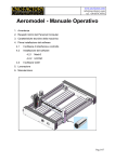
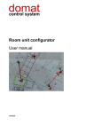
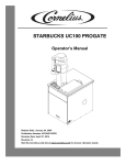
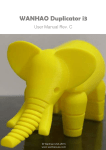
IMPORTANT: Read before using First steps with 3D printing (UCCNC) Desktop CNC / 3D system STEPCRAFT 2 – 210/300/420/600/840 Call for consumer information Customers from outside the U.S. STEPCRAFT GmbH & Co. KG Kalkofen 6 58638 Iserlohn Germany Phone: 0049-2371-9748574 Email: [email protected] Customers from the U.S. / Canada STEPCRAFT Inc. 733 E Main St. Unit 3 Torrington, CT, 06790 United States Phone 001-203-5561856 Email [email protected] Original instructions Date of: 01. June 2015 1 NOTICE All instructions, warranties and other collateral documents are subject to change at the sole discretion of STEPCRAFT, Inc. For up-to date product literature, visit www.stepcraft-systems.com for customers from Europe or www.stepcraft.us for customers from US / Canada and click on the service & support tab for this product. Meaning of special language The following terms are used throughout the product literature to indicate various levels of potential harm when operating this product: The purpose of safety symbols is to attract your attention to possible dangers. The safety symbols, and their explanations, deserve your careful attention and understanding. The safety warnings themselves do not eliminate any danger. The instructions or warnings they give are not substitutes for proper accident prevention measures. NOTICE CAUTION WARNING Procedures, which if not properly followed, create a possibility of physical property damage AND a little or no possibility of injury. Procedures, which if not properly followed, create a probability of physical property damage AND a possibility of serious injury. Procedures, which if not properly followed, create a probability of property damage, collateral damage, serious injury or death OR create a high probability of superficial injury. Safety alert: Indicates caution or warning. Attention is required in order to avoid serious personal injury. Read the ENTIRE instruction manual in order to become familiar with the features of the product and how to operate them. Failure to operate the product correctly can result in damage to the product, personal property and cause serious injury, electric shock and/or fire. This is a sophisticated hobby and semi-professional product for advanced craftsmen with previous experience in the operation of tools such as electric drills, routers and computerized tools like CNC routers or 3D printers. It must be operated with caution and common sense and requires some basic mechanical ability. Failure to operate this product in a safe and responsible manner could result in personal injury or damage to the product or other property. This product is not intended for use by children without direct adult supervision. Do not attempt disassembly, use with incompatible components or augment product in any way without the approval of STEPCRAFT GmbH & Co. KG or STEPCRAFT, Inc. This manual contains instructions for safety, operation and maintenance. It is essential to read and follow all the instructions and warnings in the manual, prior to assembly, setup or use, in order to operate correctly and avoid damage or serious injury. Age recommendation: For advanced handcrafters ages 14 and above. This is not a toy. SAVE ALL WARNINGS AND INSTRUCTIONS FOR FUTURE REFERENCE. Should you encounter any doubts or require any further information, please do not hesitate to contact us before commissioning of the system and/or the spindle. Our contact details can be found on the front page of this manual. The term “spindle” in the warnings refers to your mains-operated (corded) power supply and the spindle itself. This could be a third-party product or the STEPCRAFT high frequency spindle. The term “machine” or “system” in the warnings refers to your mains-operated (corded) power supply and the STEPCRAFT CNC /3D desktop system itself. General safety precautions and warnings This tool is controlled by a computer. Within operation it cannot be directly controlled. Missing caution or program errors can cause unexpected movement. Always ensure you fully understand the control program on your computer and how it affects the movement of the tool. Always operate your tool indoors on a solid horizontal table or workbench. Always carefully follow the manufacturer directions and warnings for any related equipment (i.e. 3D print spindles, 3D print heads, drag knifes, etc.). Always keep the product, related tools, small parts and electrical components out of the reach of children. Always keep children well out of the vicinity of this product. Always keep hair secured above your shoulders so it cannot get caught in the linear guides or the rotating tools. Continued on next page Continued on next page Always avoid water exposure to all equipment not specifically designed and protected for the purpose. Moisture causes damage to electronics. Never maintain and operate this product at poor light settings. Always ensure all clamping accessories for insertion tool, machine guided tool and workpiece are secure before usage. Always store product in a dry, temperate and secure location. Do not touch the nozzles / hot ends, insertion tools or motors as they can become extremely hot during use. Do not operate this tool outside. Always ensure the emergency switch is properly set before operating. Always ensure you understand the product and how to operate it. Only use STEPCRAFT-approved replacement parts and accessories for this product. Never place any portion of the tool or the related accessories in your mouth as it could cause serious injury. Never operate your desktop 3D system with a computer operated on battery. Never connect the tool unless using or testing the tool. Do not perform maintenance with the power supply installed. Never operate this product if you are tired, ill, taking any kind of medication or are under the influence of alcohol or drugs. Never spray ignitable liquids or any other liquid on this product. Always keep hair and dangling or loose items well away from the insertion tools when the power supply is connected. Do not use this product to create any kind of implants, either for humans or animals. NOTICE: Modification with non-STEPCRAFT-approved components may result in refusal of service by STEPCRAFT. This is a desktop 3D system that can hold tools with sharp blades spinning at very high RPM or tools getting really hot. Always use extreme caution and common sense when maintaining and operating this product. If you are unsure about ANY function or procedure described in this manual, DO NOT operate. Contact STEPCRAFT product support for assistance. Always ensure you are operating the tool at a safe distance, 3 feet (1 meter), away from yourself and others. 3 TABLE OF CONTENTS 1 GENERAL NOTES ..........................................................................................................5 2 Work preparation (desktop 3D system) ...........................................................................5 3 4 2.1 Installing the software...............................................................................................5 2.2 Installing the machine parameters ............................................................................5 2.3 Connecting the machine to the computer .................................................................6 2.4 Checking operational readiness ...............................................................................7 2.5 Manual test ..............................................................................................................8 2.6 Verification of the linear axes ...................................................................................9 2.7 Homing.....................................................................................................................9 Work preparation ...........................................................................................................10 3.1 Fixation of the print table ........................................................................................10 3.2 Importing the pattern ..............................................................................................11 3.3 Definition of workpiece zero point (X, Y) .................................................................12 3.4 Preparation of the 3D print head ............................................................................13 3.5 Definition of workpiece zero point (Z) .....................................................................14 Starting the first 3D print process ..................................................................................17 4 1 GENERAL NOTES This manual is intended to familiarize you with your desktop CNC / 3D system and to provide you with all the information you need in order to produce your first 3D print workpiece. These instructions equally apply to the desktop CNC / 3D systems STEPCRAFT-2/210, /300, /420, /600 and /840, referred to in the following as STEPCRAFT. In order to operate the machine safely and professionally please read through this entire manual and all additional documentation provided prior to your first usage of your machine: 1. 2. 3. Operating instructions of your STEPCRAFT system Operating instructions of your STEPCRAFT 3D print head FDM 1.75 or the documentation provided of your third-party 3D print head tool User manual of the CNC control software To minimize the risk of injury and / or to prevent property damage, only operate the machine and the associated control unit when you are sure you have understood all of these instructions in their entirety. Should questions arise, please contact us. Our contact details can be found on the front page of this manual. 2 WORK PREPARATION (DESKTOP 3D SYSTEM) The following installation and testing instructions only apply to machines with a parallel interface and the control software UCCNC. For buyers of the machine with an USB port together with the control software WinPC-NC, ask for the appropriate documentation. 2.1 INSTALLING THE SOFTWARE NOTICE: UCCNC comes with a STEPCRAFT desktop 3D system. This should only be connected to the computer when the software is completely installed and necessary drivers have been copied. The installation of UCCNC is an easy to use set up program. Please insert the CD into the drive and wait for the automatic installation to start. If it does not start within a few seconds, run the SETUP.EXE program from the CD. NOTICE: The complete UCCNC software installation process is documented in the user manual of UCCNC. Please refer to document “UCCNC_usersmanual.pdf” in the /manual/ folder of the UCCNC CD. Do not forget to copy the user license of UCCNC into the UCCNC installation directory! 2.2 INSTALLING THE MACHINE PARAMETERS After installation of the UCCNC software you need to install the appropriate STEPCRAFT machine parameters for UCCNC. Start “Screensetinst.exe” in the /Stepcraft/ folder: Choose your type of machine size (210 to 840) and type of machine series (Stepcraft 1 or 2) and install the 3D print configuration to operate the 3D print head. 5 Start the installation. The installation will create a desktop icon and prepares, for example, different technical th parameters for the 4 axis. In the 3D print configuration a plugin will be installed additionally to control the 3D print head. NOTICE: You can start UCCNC in the 3D print configuration with the STEPCRAFT parameters by clicking this icon. Always make sure that you choose the correct parameter setting / start icon for the intended machine operation. 2.3 CONNECTING THE MACHINE TO THE COMPUTER After completing the software installation, connect the AC adapter to the power supply and the STEPCRAFT desktop 3D system. Connect the machine / the UC100 device with the enclosed USB cable to the computer and launch the program: 6 Every time you start the program, the reset-button in the bottom-right corner is flashing. NOTICE: Release the emergency switch from the machine and make sure that no reference switch of the machine is being pressed. Press the reset-button. The machine is ready for operation now. 2.4 CHECKING OPERATIONAL READINESS After completing the software installation, the machine is ready. You can check the status of the machine via the LEDs on the control board at the rear of the machine: (left-to-right direction. UC100 device LED 1 and LED 2, control board LED 1 and LED 2) Status 1 Control board LED 1 (green) Status = on Control board LED 2 (green) Status = on Voltage is applied at (5V) 2 Sharing ok, output stage switched on, emergency switch switched off Status = off Voltage is applied at (5V) 3 Release not OK, off stage, emergency switch switched on Status = off Status = on Status = off 7 Status Control board LED 1 (green) Release not OK, end stage switched off, power is not active Control board LED 2 (green) Power disabled Status 1 UC100 LED 1 (green) Status = on UC100 LED 2 (blue) Status = on Existing USB-connection Status = on UCCNC program is online / started Status = off Existing USB-connection UCCNC program is offline / not started / in demo mode Status = off 2 3 Status = off No existing USB-connection 2.5 UCCNC program is offline / not started / in demo mode MANUAL TEST Please refer to item 2.7 if you are already familiar with the manual jog menu of UCCNC. If the STEPCRAFT is in status 1/1, it can now be moved manually. NOTICE: Furthermore, the proper assembly of the machine, according to assembly instruction, is an essential requirement. Additionally, you need to ensure that the lead screws and the linear axes are greased according to the maintenance plan of the STEPCRAFT. Now open the manual jog menu by moving the mouse pointer to the left side of the main screen: Move the cursor to the arrow keys and place the machine carefully in the middle of the workspace of the system. To increase the moving speed you can adjust the jog feed. Jog feed 10% = 300 mm/s Jog feed 100% = 3,000 mm/s 8 The 3D printer plugin is not ready to work because of the missing homing sequence (see later item 2.7): 2.6 VERIFICATION OF THE LINEAR AXES Please refer to item 2.7 if you have already done the verification (see also the assembly manual and the first steps manual). NOTICE: The machine must be noiseless and needs to move without friction and tension in all linear axes. NOTICE: If you have already levelled the machine you can skip this item and proceed with item 2.7. For checking, please proceed as follows: - Place the machine on a level surface. - First loosen the screws of the gantry parts of the X-axis (see instructions 5.2 and 5.4), the rear (see instruction 6.5) and the front (see instruction 8.10) of the Y-axis. - Move the Z-axis manually to an average height. - Move the X-axis manually to each end of the gantry and tighten the screws of each gantry part. - Now move the Y-axis towards the back and tighten the screws of the rear panel firmly. - Lastly proceed now towards the front and tighten the screws of the front panel. NOTICE: If you do not reach the final position of an axis in this way, then you must check the smooth running of linear axes and spindles. To do this, close the WinPC-NC / UCCNC or any other CNC control program and unplug the machine from the electricity supply. The X- and Z- axis can then be moved by hand over the axis connector (part 58). For movement of the Y-axis remove the tooth belt cover (part 75), and possibly also the tooth belt (part 73), in order to check the axes individually. 2.7 HOMING Before you can start to work, the machine has to be homed (pick-up the reference point or machine zero-point). Press the “home all” button in the main screen: The machine will start driving all axes now, beginning with the Z-axis, until it reaches the reference switch of each axis. When the homing is completed, the machine (seen from the front) features (X) on the left, (Y) at the rear and (Z) at the top. 9 At the same time, the reference for the machine zero point is initialized (above example for STEPCRAFT-2/300). The X-axis and the Z-axis will be initialized with 0, the Y-axis with the possible traverse distance. Notice: The actual machine zero point is (front view) left (X), front (Y), top (Z). Notice that the reference switch for the Y-axis is at the rear but the machine zero point for the Y-axis is at the front. This explains why all axes except the Y-axis will be set to zero after initialization. The reference run is to be carried out regularly after turning on the machine and before starting to work. Additionally the 3D printer plugin is ready to work (“Plugin is working!”): 3 WORK PREPARATION For further implementing the first step instruction, you are in need of the following materials: - STEPCRAFT 3D print head - Filament with diameter of 1.75 mm - Print table, e.g. acrylic table - Pair of tweezers 3.1 FIXATION OF THE PRINT TABLE First you place the offer worktop on the machine table, secondly the workpiece material. Attach the two plates with the accompanying retainers from the STEPCRAFT to the machine table. The screws need to be tightened by hand only: 10 3.2 IMPORTING THE PATTERN Open the pattern file with the “Load File” button in the main screen. Navigate to the /Examples/03-3D print directory of the UCCNC CD and open the file Stepcraft-Logo-Standard-Print.gco The file consists of a 3D pattern of the STEPCRAFT logo. The workpiece has a size of 30 x 30 mm (approx. 1.25 inch x 1.25 inch). NOTICE: The starting point for this pattern was originally set in the CAM program STEPCRAFT Repetier Host to the middle of the workpiece. It is also common to set the starting point to the edge of the workpiece, for example to the left front corner. Every time you import an already existing work file you have to make sure where the starting point of the CNC code is. 11 3.3 DEFINITION OF WORKPIECE ZERO POINT (X, Y) Do not turn the print head on. Chuck the 3D print tool into the spindle. Lock the 3D print head into the tensioning system with an Allen key. Beside the knowledge of the starting point of the CNC code you need to define the starting point on the work sheet. This point is also called workpiece zero point. Highlight this point with an "X". Make sure that, when seen from the front, there is sufficient travel available to the left and right and to the front and rear side (at least 40 50 mm in each direction). Open the "jog" menu by moving your mouse pointer about the left screen side of the program and then drive the machine manually to the point marked. Move the Z-axis to half maximum height. Alternatively you can also use the cursor keys (left, right, top, down, picture up / down) of the keyboard to jog the gantry. Save these settings by clicking "Zero all" in the main screen. 12 The workpiece coordinates are then X = 0.000, Y = 0.000 and Z = 0.000. The yellow dot in the toolpath preview marks the actual position of the machine and is located in the centre of the workpiece as expected. NOTICE: If you do not see the yellow dot in the centre of the workpiece toolpath, repeat item 2.7 and 3.3. 3.4 PREPARATION OF THE 3D PRINT HEAD Stay alert, watch what you are doing and use common sense when operating the 3D print head. Do not use the 3D print head while you are tired and / or under the influence of drugs, alcohol or medication. A moment of inattention while operating heated tools may result in serious personal injury. Use personal protective equipment. Protective equipment will reduce personal injuries. Prior to first usage, read the operating instructions of your STEPCRAFT 3D print head thoroughly and carefully, making sure you have understood everything. Pos. 1. Description Before insertion of filament it has to be cut cleanly, e.g. with a pair of pliers. 2. Pull the filament supply from the housing. 3. Unscrew the adjusting screw for the filament pinch four turns. 4. Insert the filament thread into the print head. Picture 13 Pos. 5. Description NOTICE: The filament thread is guided by the brass roller. 6. Turn the adjustment screw carefully and as far as it will go (clockwise) until it can no longer be turned. Then, turn the adjustment screw half turn to the left. Now the print roller is set correctly. 7. Push the filament supply back into the housing. 8. Connect the control unit of the 3D print head with the power supply and the mainboard of the STEPCRAFT 3D desktop system. Turn the control unit of the printer on; set the temperature to 190° C. Picture After the operating temperature is being reached, start to exhaust the system. The filament must be boosted with moderate forward jogging of the 4th axis (max. speed 20%) until a clean thread is printed out. 9. CAUTION: Hot! Remove the thread, e.g. with a pair of tweezers. NOTICE: If the filament is already inserted into the 3D print head, only steps 8 and 9 apply. 3.5 DEFINITION OF WORKPIECE ZERO POINT (Z) The workpiece zero point (Z) is the point where the end mill touches the surface of the workpiece. Jog carefully with the nozzle of the 3D print head towards the print table. 14 Take a piece of paper, place it onto the print table and proceed slowly and manually in the Z-axis downwards towards the print table. Move the paper back and forth with your fingers. Once the nozzle touches the paper, save that point again as the workpiece zero point X / Y / Z by pressing “Zero all”. The 3D print head may not stay on the paper / the surface of the print table longer than 10 seconds! The tool has to been lifted as soon as possible. Risk of fire! 15 After this, move the Z-axis manually up to approx. 20 mm above the print table. 16 4 STARTING THE FIRST 3D PRINT PROCESS Stay alert, watch what you are doing and use common sense when operating a power tool. Do not use a power tool while you are tired and / or under the influence of drugs, alcohol or medication. A moment of inattention while operating power tools may result in serious personal injury. Use personal protective equipment. Always wear eye protection. Protective equipment will reduce personal injuries. Prior to first usage, read the manual of your STEPCRAFT 3D print head thoroughly and carefully, making sure you have understood everything. Speed will be automatically controlled by UCCNC. Be aware that the temperature of the 3D print head is controlled manually and you have to switch off the control unit after the job has been finished. Now press the “cycle start” button. The machine moves from the workpiece zero point X = 0.000 and Y = 0.000 to the start point of the first outline down to Z = 0.300. The manufacturing starts. Do not reach inside the working area of the 3D print head while it is in operation. Contact with the moving parts during operation may result in poor build quality, equipment damage or personal injury. Do not leave the 3D print head unattended during operation. Use of 3D print head by persons unfamiliar with these warnings and instructions may result in equipment or property damage and personal injury. After completing the work process, the system automatically moves to the workpiece zero point (X, Y) and to the top Z-axis position. Turn off the 3D print head and move the gantry to the rear end of the desktop system. 17 Use personal protective equipment. The use of protective equipment such as heat resistant gloves and safety glasses will reduce personal injuries. Be aware of your body position when using hand tools to remove objects from the print table. Sudden tool slip and improper body position during object removal from the print table may result in personal injury. Remove the workpiece carefully. Congratulations! You have completed your first 3D workpiece with your STEPCRAFT. 18 NOTES 19 Copyright © STEPCRAFT® 20