1
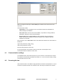
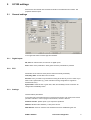
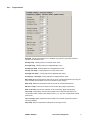
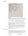
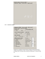
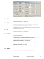
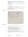
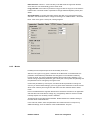
Room unit configurator
User manual
V04/08
1
Contents
1
Contents .............................................................................................................2
2
Introduction .........................................................................................................3
3
Hardware configuration.......................................................................................3
4
4.1
4.2
4.3
Module detection ................................................................................................3
Communication settings..................................................................................4
Scanning the bus ............................................................................................4
Possible problems...........................................................................................5
5
5.1
5.2
5.3
UC100 settings ...................................................................................................6
General settings ..............................................................................................6
Tabs with setpoints and parameters ...............................................................7
Time schedule...............................................................................................13
6
6.1
6.2
UI011 settings...................................................................................................14
General .........................................................................................................14
Tabs with setpoints and parameters .............................................................16
7
7.1
7.2
Advanced functions ..........................................................................................24
Address .........................................................................................................24
Info ................................................................................................................25
Any comments, questions and improvement suggestions to this manual are welcome at
[email protected]. Thank you for your feedback.
www.domat.cz
RcWare SoftPLC
Room unit configurator
2
2
Introduction
The configuration software domat.exe is used for addressing and configuring of all
Modbus-based Domat Control System I/O modules, room units, and room controllers.
It is used by system engineers for pre-configuration in the office as well as by
commissioning staff for I/O check and controller settings.
Domat.exe runs in the Microsoft.NET V2.0 environment; the .NET files must be installed
prior to running the software. No installation of domat.exe is necessary, just copy the
files (.exe, .dll, and data.txt) into any suitable directory.
3
Hardware configuration
Connect the room unit, I/O module, or IRC controller to serial port of your PC through a
RS232/RS485 converter, e.g. Domat M011. Power all components by 10..30V DC or
12..24 V AC.
See data sheets for terminals and correct module connection (bus end etc.).
4
Module detection
Run domat.exe. The main program window opens.
RcWare SoftPLC
Room unit configurator
3
NB. The program should open in User mode (see indication below the service code
input line).
There are three modes:
-
Light mode: It is only possible to scan and adress modules and read data. No
internal settings are available.
-
User mode: Most of the functions are available, it is possible to change address,
parameters, setpoints, and all internal settings.
-
Service mode: Same as User mode, but also possible to bring controllers to
default state (factory settings) and perform analogue input calibration (special
hardware tool needed).
If the program is not in User mode check if the data.txt file resides in the same folder as
domat.exe.
Light mode password: (empty string)
User mode password: rumcajs
Service mode password: vecernicek
It is recommended to use the User mode for daily work. All descriptions and
screenshots below are based on User mode.
4.1
Communication settings
In the Module frame, select the serial port of your PC which is connected to the module
bus. Default communication parameters are 9600, N, 1, 8; this is also the factory setting
of all modules and room units.
4.2
Scanning the bus
Click the Scan button. The address range specified in the Scan frame (default 1 to 10) is
scanned for present modules. All modules found in this range are listed in the window.
RcWare SoftPLC
Room unit configurator
4
4.3
Possible problems
No modules scanned, TxD / RxD LED at M011 dark
Check COM port number and settings. Check serial cable (must be nullmodem). Check
if COM port works with other software / hardware.
No modules scanned, TxD LED at M011 flashing, RxD LED dark
Check I/O bus cabling and polarity. Check if the internal setting of M011 is 9600, 8 bit
(DIPs 1,2 ON, 3,4 OFF – default setting). Check if Modul setting in domat.exe is 9600,
N, One, 8.
Try to bring the module / room unit into INIT mode (power off, INIT switch to ON, power
on). The slave should respond at 9600, N, 8, 1 at address 1. Try to communicate with
another (working) module or room unit to see if the converter, cabling, and software is
set properly.
Another reason may be a non-standard type of RS232/RS485 converter. Try M011 if not
used.
No modules scanned or communication dropouts, TxD / RxD LEDs flashing
Improperly terminated I/O bus (check bus termination switches at both ends), loose
wires in the connectors, or EMC disturbances. Check the communication with one
module only, apart from the cabinet and field wiring, preferably powered by a separate
power source (transformer or stabilized power supply, eg. that supplied with IPCT.1).
This may also happen with the most recent notebooks which do not have serial ports
over classical UART but over an internal USB interface (even if the notebook has the
CANNON 9 Male connector). Then the driver does not catch the fast responses of the
modules, typically M4xx, M300 etc. Try another notebook or communicate over the
process station.
Another reason may be a non-standard type of RS232/RS485 converter. Try M011 if not
used.
Unknown module type
May appear when using older versions of domat.exe which do not support certain
module / room unit types. Download the latest version at www.rcware.eu or report the
module ID together with version number of your domat.exe to [email protected].
NB. The default I/O module and room unit setting is:
Address: 1
Communication: 9600, 8, N, 1
RcWare SoftPLC
Room unit configurator
5
5
UC100 settings
Scan the bus and double click the listed controller in the field with scan results. The
properties window opens.
5.1
General settings
In the upper bar there is module type and address.
5.1.1
Digital inputs
DI1, DI2: not relevant here; UC100 has no digital inputs
Push: status of the pushbutton. Goes green when the pushbutton is pressed.
5.1.2
RTC
Parameters of the real time clock (which control the weekly scheduler).
Time, Day, Date: current data in the controller
PC Time: tick if you want to synchronize according to the time of your PC. Untick if you
want to set a special time (e.g. if the controller is being configured for supplies to
another time zone).
Synchronize: writes the PC or given time, date, and weekday into the controller. All
changes are immediately active.
5.1.3
Settings
Communication parameters.
In the upper part of the frame there is unit type (here UC100), and unit ID; each device
(module / controller / room unit) type has its own ID, UC100 = 300 hex.
Firmware version: please report if you experience problems.
Address: Modbus slave address (1..255) of the device.
New address: select or enter the new address here when readdressing the unit.
RcWare SoftPLC
Room unit configurator
6
Baudrate: for information only, can not be changed.
Write all to EEPROM: writes all the changed values (address, parameters etc.) to
permanent memory. To make new address (and baudrate) active, power off and power
on the device again. All other parameters are effective immediately.
NB. This button also stores all settings which are in the tabs on the right (operation
modes, setpoints, etc.)
5.1.4
Communication
Communication statistics (sent and received telegrams). Only relevant for Service
mode.
5.1.5
Others
Actual values
Set temp: current set temperature (PI controller setpoint) – selected temperature for
actual operation and heating / cooling mode plus manual setpoint correction
Actual temp: measured temperature by the internal sensor plus sensor compensation
Outside temp: outdoor temperature optionally writable over Modbus to the room unit or
controller; used just for display. See Controller settings, Show mode.
PID Output:: internal value of the room controller output: –100% (cooling) to 100%
(heating). This value is processed in interlocking sequences and PWM modulators
before it is sent to the outputs. For information and service only.
Other buttons and information
Connected/Disconnected – Connection status / comunication with the unit
Close: Closes the unit window and returns to main program window
<<: Switches to simplified view (no tabs with values)
Time schedule: Opens the weekly scheduler window; see below
Open/close initialization: only relevant for initialization process, see below.
5.2
Tabs with setpoints and parameters
At the right of the window, there are tabs with advanced controller settings. Only use
those settings when necessary. All settings are effective immediately and written to
RAM. Permanent writing to EEPROM follows by clicking the „Write all to EEPROM“
button, see above, Settings.
RcWare SoftPLC
Room unit configurator
7
5.2.1
Temperatures
Set temp: Actual set temperature. It is updated only when the properties window is
opened. For information only.
Set day temp.: Heating setpoint for Day/Comfort mode
Set night temp.: Heating setpoint for Night/Standby mode
Set depress.temp: Heating setpoint for Off/Depression mode
Set day cool temp.: Cooling setpoint for Day/Comfort mode
Set night cool temp.: Cooling setpoint for Night/Standby mode
Set depress. cool temp: Cooling setpoint for Off/Depression mode
Min. temp: Minimum temperature that can be set as corrected temperature (turning the
knob overrides actual setpoint until next operation mode change)
Max. temp: Maximum temperature that can be set as corrected temperature
Min d.n.d. temp: Low limit for setpoint for all modes (Day, Night, Depression)
Max d.n.d. temp: High limit for setpoint for all modes (Day, Night, Depression)
Corr temp: Temperature correction which adds to the measured temperature (to
compensate external influences). Default value is 1.5 °C which compensates internal
heat losses
Corr out temp: Optional parameter which adds to the Outside temperature before
sending to display
Step temp: Step for temperature settings when turning the knob.
RcWare SoftPLC
Room unit configurator
8
5.2.2
Digital
Digital inputs
Optional latch function is implemented to keep even short signals at digital inputs
readable: as soon as the signal appears on the input, it is written to the Modbus register.
The latched state is then kept in the Modbus register until it is read out by the master.
Latch state:
Disabled
Log(0)
Log(1)
no function
the input is normally closed, log.0 is latched
the input is normally open, log.1 is latched
Clear latch: Reads out the register and sets the optional latch to its normal state
Offline action: Requested status of the digital output if the controller is offline (no
communication from the Modbus master for a definable time). Usually None to let the
controller do its job even if offline.
Wait time: Time of non-communication (no datagrams from master to slave) which is
recognized as communication failure. It results in setting the outputs to the “Offline
action” state (if defined). Entered in seconds, 1 to 255. Select from the drop-down box
or write the value directly. If a value larger than 255 is entered, the default of 50
seconds is set.
Start action: Requested status of the digital output between power-up and the first
datagram from master. Usually None.
5.2.3
Presence mode
The Presence mode configuration tab allows to enable and disable various operation
modes. It is possible to switch between those modes either remotely, or in the controller
menu (after long push), or pressing the button shortly (short push, see the Controller
settings tab, Quick edit mode). Unchecked states are not available for the user.
However, they can be set remotely over Modbus, so that the user can switch between
RcWare SoftPLC
Room unit configurator
9
Day, Night, and Auto, while a central unit can – on top of that - set the controller to
Depression (Central Off).
Day: Comfort mode, Day temperature setpoints apply, room occupied.
Night: Reduced mode, Night temperature setpoints apply.
Depress: Depression mode, the room is unoccupied for a longer time, energy savings
temperature setpoints apply.
Auto: Temperature setpoints change according to the time scheduler between Day,
Night and Depress modes. Together with the Clock symbol, the current mode symbol(s)
is displayed.
Party: Controller goes to Comfort mode for a predefined time of 2 hours. Then it goes
back to previous mode.
5.2.4
Symbol control
Not relevant here, just to check if the symbols of spanner, boiler and alarm bell are
displayed properly.
Those symbols may be switched on and off by the Modbus master and indicate various
system statuses and system and maintenance alarms.
Click the symbol to make it active at the display. Click it again to disable it.
RcWare SoftPLC
Room unit configurator
10
5.2.5
Controller settings
Change over – this signal is usually sent to the controler over the bus according to
available media temperature; if there is hot water available, the controler should be in
the Heating mode. The default value is Heating and usually there is no need to change
this.
RcWare SoftPLC
Room unit configurator
11
Heating: sets the controller to Heating mode (valve opens if actual setpoint is above
measured temperature
Cooling: sets the controller to Cooling mode (valve opens if actual setpoint is below
measured temperature.
Sense of heat/cool symbols:
Energy: the heating and cooling symbols display the status of the change-over signal,
which actually means the type of energy which is available for heating or cooling,
regardless of the actual valve status (i.e. may be that the heating symbol is on – hot
water in the piping - but the valve is closed, as there is no need to heat the room now)
Valve: the symbol appears as soon as the valve in the corresponding mode starts to
open. This is used most, and also is the default settings.
Quick edit mode: defines the function of short push of the button.
None: short push has no effect
Presence mode: short push of the button changes between the modes predefined
(checked) in the Presence mode.
Allowed operation modes: functions and values available in the settings menu after a
super long push. This is what the user actually can control at the device.
Temperature correction: change of the actual setpoint, sets back to 0 with presence
mode change. If disabled here, even turning the knob has no effect.
Day temp ... Cooling depress temp: Setpoints for heating and cooling for Day, Night,
and Depression mode – see the Temperature tab.
Time: real time clock setting (hours, minutes, weekday).
Actual regulation mode: displays the current operation mode (Day / Night /
Depression)
Show mode: select values which periodically swap at the display in the Show mode.
Temperature: actual room temperature
Outside temp.: outside temperature – must be communicated to the controller by a
Modbus master, use as an option only
Time: real time (hh.mm, day of week together with the clock symbol)
Show time: period of swapping the values of Show mode.
Long push time: time to push the button to select the Time schedule menu.
Super long push time: time to push the button to select the Settings menu (and get
access to the settings enabled in Allowed operation modes).
Change over period: time of inactivity after the change-over signal comes, 1 to 255
mins. Intended to let the hydronic system adapt and deliver proper media temperature.
P band: proportional band of the controller; control deviation (setpoint – actual value) to
open the valve at 100 %.
I const: integrating part, time to increase the output by the P contribution at constant
deviation.
Step minutes: time resolution for time schedule settings.
Edit return time: time to return to the basic display (show mode) in case of user
inactivity.
RcWare SoftPLC
Room unit configurator
12
5.2.6
Serial port settings
Baudrate: for information only, to be changed in the main window (see above: General
setings, Settings)
Parity: None, Even, Odd, default is None.
Stopbits: One or Two, default is One.
5.3
Time schedule
The weekly time schedule in the controller is stored in EEPROM and controls the
operation modes according to real time clock and the defined settings. Each of the 7
days has 6 events which either can be disabled or set the controller into a particular
operation mode (Day / Night / Depression). A disabled event does not influence the
operation mode and it does not matter what time (hh:mm) it is set to.
Click the Time schedule button in the main window to open the Time schedule window.
There are predefined events. The Edit button at each weekday copies this particular
weekday to the Schedule settings frame. Then it is possible to modify the events of the
day:
Time: for your comfort, type “1205” to set 12h 05m. No colon necessary.
Value: select from the drop-down box (Day, Night, Depression, Disabled).
After all six events are defined, click Set schedule to write the schedule to the controller.
If multiple days are marked (ticked) prior to pressing the Set schedule button, the same
schedule is written to all of them.
In the graphic pan on the left there is the complete weekly list of changes; the closer the
blue and red setpoint lines are, the more comfortable the mode is. The graph does not
reflect real temperature values, it is just a symbolic representation of the operation
modes.
RcWare SoftPLC
Room unit configurator
13
After you have finished the editing, click the Write all to EEPROM button. The data is
written permanently to the controller’s memory. The progress bar above the button
shows the writing progress, in the end of the process there comes a pop-up window
Writing complete.
Click Close to close the Time schedule window and return to the main controller
window.
6
UI011 settings
The UI011 is a room unit with no control function. It only provides actual temperature
and user-entered data to a master device (PLC or any controller) and displays operation
statuses, alarms etc. For full descrition of the master to UI011 communication, see the
Room units and controllers: Communication protocol description document.
Scan the bus and double click the listed controller in the field with scan results. The
properties window opens.
6.1
General
In the upper bar there is module type and address.
6.1.1
Digital
DI1, DI2: not relevant here; UI011 has no digital inputs
Push: status of the pushbutton. Goes green when the pushbutton is pressed.
Relay 1, Relay 2: not relevant here; UI011 has no digital outputs
RcWare SoftPLC
Room unit configurator
14
6.1.2
RTC
Not relevant here; UI011 has no real time clock.
6.1.3
Temp
Set temp: Temperature setpoint set by user. The setpoint can be changed in the
Min...Max limits defined in the Temperature tab – see below.
Actual temp: Actual measured room temperature inclusive correction Corr defined in
the Temperature tab – see below
6.1.4
RH
Not relevant here, UI011 has no humidity sensor
6.1.5
Settings
Communication parameters.
In the upper part of the frame there is unit type (here UI011), and unit ID; each device
(module / controller / room unit) type has its own ID, UI011 = 201hex.
Firmware version: please report if you experience problems.
Address: Modbus slave address (1..255) of the device.
New address: select or enter the new address here when readdressing the unit.
Baudrate: 1200...19200 bps.
Com. errors: Communication error counter.
Com. OK: Number of correctly received packets.
Connected/Disconnected – Connection status / comunication with the unit
6.1.6
Others
End: Closes the unit window and returns to main program window
RcWare SoftPLC
Room unit configurator
15
Write all conf. to EEPROM: writes all the changed values (address, parameters etc.) to
permanent memory. To make new address and baudrate active, power off and power on
the device again. All other parameters are effective immediately.
NB. This button also stores all settings which are in the tabs on the right (operation
modes, setpoints, etc.)
<<: Switches to simplified view (no tabs with values)
Save: Saves the actual settings of the unit to a file. The settings can be retrieved for
download of the same configuration to more units.
Load: Loads settings from a file. The loaded settings are written to the device’s memory
(as if they were entered manually). For permanent saving, click Write all conf. to
EEPROM.
6.2
Tabs with setpoints and parameters
At the right of the window, there are tabs with advanced controller settings. All settings
are effective immediately and written to RAM. Permanent writing to EEPROM follows by
clicking the „Write all conf. to EEPROM“ button, see above, Others.
6.2.1
Temperature
Set temp: Temperature setpoint, for writing only. Actual temperature setpoint is
displayed and continuously updated in the Temp section – see above. Writing to this
variable has the same effect as changing the setpoint by turning the knob.
Set day temp: Setpoint for day mode.
Set night temp: Setpoint for night mode.
Both those setpoints can be set and read by the master device.
Dec show places: may be 0, 1, or 2 – number of decimal places to display the actual
temperature. Example:
0
1
2
23 °C
23.2 °C
23.27 °C
RcWare SoftPLC
Room unit configurator
16
Dec set places: may be 0, 1, or 2 – number of decimal places to display when changing
a setpoint.
Min, Max: Minimum and maximum limits for changing the temperature setpoint. May
also be relative, such as Min: -3.5, Max: +3.5 °C. The interpretation must be
programmed at the master device.
Corr: Internal correction; adds to the measured temperature before it is displayed and
send to the Modbus table. The default value of 1.5 °C compensates the internal heat
dissipation within the room unit.
Step: Value to change setpoint on one step of the knob. The knob has 24 steps to
complete one turn.
Set outside temp: Outside temperature at which heating mode starts. Symbols:
Thermometer, Empty house. This temperature can be set by the user and then read by
master for further processing in the primary heating circuits. It is set in whole degrees
(no decimals) in the Min.. Max range:
Min, Max: Minimum and maximum limits for changing the outside temperature to start
heating.
Set DHW temperature: Setpoint of domestic hot water. Symbols: Water tap. This
temperature can be set by the user and then read by master for further processing in the
DHW preparation circuit. It is set in whole degrees (no decimals) in the Min.. Max range:
Min, Max: Minimum and maximum limits for changing the DHW temperature setpoint.
Set heating curve: Type of heating curve (relation between outside temperature and
heating water setpoint). Symbols: Heating, Boiler. Can be set to 1, 2, 3, or 4. It may be
read by master for further processing in the heating circuit.
6.2.2
Humidity
Parameters for setting relative humidity setpoint.
Set RH: Humidity setpoint set by user.
Min RH, Max RH: Minimum and maximum rH values the user is allowed to set by
turning the knob.
RcWare SoftPLC
Room unit configurator
17
Corr RH: Internal correction; adds to the measured relative humidity before it is
displayed and send to the Modbus table. Not relevant now as UI01x does not contain
humidity sensor.
Dec show places: may be 0, 1, or 2 – number of decimal places to display the actual
relative humidity. Example:
0
1
2
45 %rH
45.2 %rH
45.25 %rH
Not relevant here as UI01x does not contain humidity sensor.
Dec set places: may be 0, 1, or 2 – number of decimal places to display when changing
the relative humidity setpoint.
Step1: Value to change relative humidity setpoint on one step of the knob. The knob
has 24 steps to complete one turn.
6.2.3
Digital
Not relevant here as UI010 and UI011 have no digital inputs and outputs.
6.2.4
Settings
The Show mode defines swapping of displayed values. There may be up to 5 different
values periodically displayed:
Temperature – actual (measured) temperature incl. correction
Humidity - actual (measured) humidity incl. correction (not relevant for UI01x)
Time – real time of the internal clock (not relevant for UI010, UI011)
Remote 0 – any value sent from the master, see below
Remote 1 – any value sent from the master, see below.
The checked values are periodically changed at the display. By pushing the button the
unit goes from Show mode to Quick edit mode or Edit mode.
Show time: period to display each of the values selected in Show mode. Default: 2
secs.
RcWare SoftPLC
Room unit configurator
18
Edit return time: Timeout – if user inactivity in the Edit mode is longer than the Edit
return time, the unit automatically goes to Show mode.
Long push time: if the button is pushed for Long push time or longer, the unit switches
to Edit mode. In the Edit mode it is possible to change selected setpoints (values) and
states.
Quick edit mode: by pushing the button shortly (less than Long push time) the value
selected in the Quick edit mode is changed according to its enabled states – see below.
None: if the unit is given a short push, nothing happens.
6.2.5
Modes
Probably the most important part of the functionality of the unit.
After the unit is given a long push, it switches to the Edit mode. In the Edit mode it is
possible to select different parameters and change them. The selection follows by
turning the knob. The active parameter together with its symbol set is flashing. If you
want to change a particular parameter, give a short push. The symbols stop flashing and
the parameter can be changed by turning the knob.
Confirm the parameter by a short push, and select another parameter to change. As
soon as you have finished settings, give a long push which switches the unit back to the
Show mode. Inactivity time longer than Edit return time also switches back to Show
mode.
Here in the Modes tab the engineer selects which modes are relevant for his application
and what the user will be able to change. E.g. it apparently makes no sense to enable
humidity setpoint if no humidity control is installed.
The Modes tab incorporates several subtabs. Switch between the subtabs clicking on
the lower brink of the Modes tab.
In the main tab, Others, there are parameters and values which do not require any
additional settings, such as selection of the enabled states. They are:
RcWare SoftPLC
Room unit configurator
19
Temp: Temperature setpoint. If disabled, it can not be changed even by turning the
knob in the Show mode. Symbols: °C/°F
Humidity: Relative humidity setpoint. Symbols:%rH.
Remote 0: Any value read and written by master. See the Remote 0 tab.
Remote 1: Any value read and written by master. See the Remote 1 tab.
Day temp: Temperature setpoint for Day mode. Symbols: Thermometer, Sun.
Start heating temp: Outside temperature at which heating mode starts. Symbols:
Thermometer (outside the) Empty house.
Night temp: Temperature setpoint for Night mode. Symbols: Thermometer, Moon.
DHW Temp: Domestic hot water setpoint. Symbols: Thermometer, Water tap.
Heating curve: Heating curve type (1..4). Symbols: Heating, Boiler.
At the screenshot above, the modes Temperature setpoint (room), Start heating at...,
and Heating curve are enabled. This means that the user can change room temperature
setpoint, outside temperature at which heating is enabled or disabled, and heating curve
type. Those values can be read out by the master. No other values are available for the
user except those for display selected in the Show mode.
Another modes are in the other subtabs. Enable each of those modes if the user is
allowed to change it. Enable the mode also if it should be changed in the Quick edit
mode.
Check the states that the user may select from. For instance on the screenshot below
the user only can select between Comfort and Standby modes, however, the presence
mode can be set to Off remotely from the master.
6.2.6
Presence mode
Comfort: maximum heating and minimum cooling temperature, all aggregates are
functional. Symbols: Occupied house.
Standby: Temporary absence. Symbols: Empty house.
Off: Long-term absence, holidays, weekend, room unoccupied etc. Symbols: Off
symbol.
RcWare SoftPLC
Room unit configurator
20
Party: Temporary occupancy, long office hours etc. Should be set back to Standby after
a certain time (usually 2 hours) by master.
6.2.7
Day / night mode
The Day / night mode is mainly used for residential applications.
Day auto: Day mode set by a time scheduler (this is done by master; the UI010 and
UI011 do not possess real time clock). Symbols: Clock, Sun.
Night auto: Night mode set by a time scheduler. Symbols: Clock, Moon.
Day manual: Manual override to Day mode, or just Day mode if scheduler not present.
Symbols: Sun.
RcWare SoftPLC
Room unit configurator
21
Night manual: Manual override to Night mode, or just Night mode if scheduler not
present. Symbols: Moon.
Off: Energy savings mode, long-term unoccupancy.
6.2.8
Fan
For applications where manual fan control is required (fancoils, split units, convectors).
Auto: Fan stages controlled by the master. Will probably also display actual fan stage
(written by master, see the Modbus table). Symbols: Fan, A.
Off: Manual off. Symbols: Fan, M.
Man1: Fan manually on Stage 1. Symbols: Fan, M, Stage1.
Man2: Fan manually on Stage 2. Symbols: Fan, M, Stage2.
Man3: Fan manually on Stage 3. Symbols: Fan, M, Stage3.
6.2.9
Heat / cool mode
For split units, heat pumps etc.
Off: Unit is off, no operation. Symbols: Off.
Heat only: Heat only mode, cooling disabled. Symbols: Heat.
Cool only: Cool only mode, heating disabled. Symbols: Cool.
Fan only: Brings fresh air in or air circulation without energy (heating / cooling).
Symbols: Fan.
Auto: Heating or cooling according to actual energy demand, both functions enabled.
Symbols: Heat, Cool.
RcWare SoftPLC
Room unit configurator
22
6.2.10 Symbol control
Not relevant here.
6.2.11 Remote 0
Defines the way Remote value 0 is displayed and set.
Step: Value to change setpoint on one step of the knob. The knob has 24 steps to
complete one turn.
Min, Max: Minimum and maximum limits for changing the value by user.
Show place: Number of decimal places to display.
Set place: Number of decimal places to display when setting the value.
RcWare SoftPLC
Room unit configurator
23
See the Modbus table for a detailed overview of values to read wnd write the Remote
value 0 by master.
6.2.12 Remote 1
Same as Remote 0, but defines the way Remote value 1 is displayed and set.
7
Advanced functions
7.1
Address
The domat.exe tool also brings advanced Modbus addressing functions.
1.
Start the tool in User mode.
2.
Check if the modules are connected by scanning the bus.
3.
Instead of clicking directly to the module address, click the Address button.
4.
Enter a valid module address in the Connect modul: Address field.
5.
Click Connect.
A table with read values from the controller or room unit opens. Here it is possible to
read and write firectly to the Modbus registers of the device.
Please keep in mind that this is an activity which requires advanced knowledge of the
register table. By improper writing, the device may be damaged.
1. Click a register row to open a window for writing.
RcWare SoftPLC
Room unit configurator
24
2. Enter a new value in your favorite format.
3. Click Set if you want to set the new value and leave the dialog open. Click Set and
close to set the new value and close the dialog. Click Close to cancel the operation.
7.2
Info
In the main program window, click the Info button.
In the window there is a list of all the supported modules. Check here if the tool is not
able to detect your module / room unit / controller.
RcWare SoftPLC
Room unit configurator
25