1
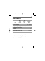
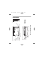
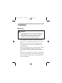
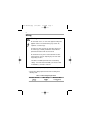
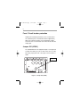
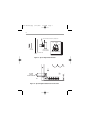
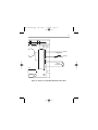
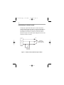
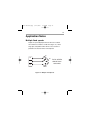
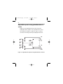
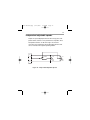
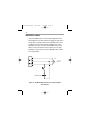
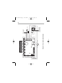
250-0419r0.qxp
7/12/2006
7:56 AM
Page a
USER’S MANUAL
170-205-0016
Pulse-Width Modulated,
Adjustable Speed Drives
for DC Brush Motors
250-0419r0.qxp
7/12/2006
7:56 AM
Page b
The 170-205-0016 chassis drive accepts a DC input voltage and output a DC
power voltage to control the speed of a low voltage motor. The speed may be
controlled with a potentiometer or an external voltage signal.
Standard Features:
• Provides smooth variable capability for mobile equipment.
• Maintains variable speed control as batteries discharge.
• Adjustable min speed, max speed, IR compensation, current limit, and accel.
• Inhibit terminal permits optional start-stop without breaking battery lines.
• Speed potentiometer included.
• Increases range or running time of battery operated equipment through high
efficiency.
• Power LED gives a visual indication when power is applied to the drive.
• Jumper reconnectable for low or high voltage.
Copyright © 2006 by
Bison Gear & Engineering
All rights reserved. No part of this manual may be reproduced or transmitted in any
form without written permission from Bison Gear & Engineering. The information and
technical data in this manual are subject to change without notice. Bison Gear &
Engineering and its Divisions make no warranty of any kind with respect to this
material, including, but not limited to, the implied warranties of its merchantability
and fitness for a given purpose. Bison Gear & Engineering and its Divisions assume
no responsibility for any errors that may appear in this manual and make no
commitment to update or to keep current the information in this manual. MVD062702
Printed in the United States of America.
250-0419r0.qxp
7/12/2006
7:56 AM
Page i
i
Safety Warnings
• This symbol denotes an important safety tip or warning.
SHOCK
HAZARD
AVOID
HEAT
KEEP
DRY
AVOID
VIBRATION
Please read these instructions carefully before performing
any of the procedures contained in this manual.
• DO NOT INSTALL, REMOVE, OR REWIRE THIS EQUIPMENT
WITH POWER APPLIED. Bison assumes the qualified
technician is intimate with the dangers involving batteries,
especially lead-acid type. This manual presupposes that you
have taken all the necessary precautions to prevent a potentially
fatal accident involving such batteries, and have followed all
standard electrical precautions.
•
Reduce the chance of an electrical fire, shock, or explosion by
proper grounding, over-current protection, thermal protection,
and enclosure. Follow sound maintenance procedures.
It is possible for a drive to run at full speed as a result of
a component failure. Bison strongly recommends the
installation of a master switch in the main power input to stop
the drive in an emergency.
This drive is isolated from earth ground. Avoid direct
contact with the printed circuit board or with circuit elements to
prevent the risk of serious injury or fatality. Use a non-metallic
screwdriver for adjusting the calibration trimpots. Use
approved personal protective equipment and insulated tools if
working on this drive with power applied.
250-0419r0.qxp
7/12/2006
7:56 AM
Page ii
ii
Contents
Safety Warnings
i
Specifications
1
Dimensions
2
Installation
3
Mounting . . . . . . . . . . . . . . . . . . . . . . . . . . . . . . . . . . . . . . . . . . . . .3
Wiring . . . . . . . . . . . . . . . . . . . . . . . . . . . . . . . . . . . . . . . . . . . . . . .4
Shielding Guidelines . . . . . . . . . . . . . . . . . . . . . . . . . . . . . . . . . . .5
Fuse / Circuit breaker protection . . . . . . . . . . . . . . . . . . . . . . . . . .6
Jumper 501 (JP501) . . . . . . . . . . . . . . . . . . . . . . . . . . . . . . . . . . .6
Speed adjust potentiometer . . . . . . . . . . . . . . . . . . . . . . . . . . . . . .7
Connections . . . . . . . . . . . . . . . . . . . . . . . . . . . . . . . . . . . . . . . . . .9
Voltage follower . . . . . . . . . . . . . . . . . . . . . . . . . . . . . . . . . . . . . .12
Operation
13
Before applying power . . . . . . . . . . . . . . . . . . . . . . . . . . . . . . . . .13
Startup and shutdown . . . . . . . . . . . . . . . . . . . . . . . . . . . . . . . . .14
Starting and stopping methods . . . . . . . . . . . . . . . . . . . . . . . . . . .15
Inhibit terminals . . . . . . . . . . . . . . . . . . . . . . . . . . . . . . . . . . . . . .17
Power LED (IL501) . . . . . . . . . . . . . . . . . . . . . . . . . . . . . . . . . . .18
Calibration
19
MINIMUM SPEED (MIN SPD) . . . . . . . . . . . . . . . . . . . . . . . . . . .20
MAXIMUM SPEED (MAX SPD) . . . . . . . . . . . . . . . . . . . . . . . . . .20
ACCELERATION (ACCEL) . . . . . . . . . . . . . . . . . . . . . . . . . . . . .21
IR COMPENSATION (IR COMP) . . . . . . . . . . . . . . . . . . . . . . . .22
CURRENT LIMIT (CUR LIMIT) . . . . . . . . . . . . . . . . . . . . . . . . . . .23
250-0419r0.qxp
7/12/2006
7:56 AM
Page iii
iii
Application Notes
25
Multiple fixed speeds . . . . . . . . . . . . . . . . . . . . . . . . . . . . . . . . . .25
Adjustable speeds using potentiometers in series . . . . . . . . . . .26
Independent adjustable speeds . . . . . . . . . . . . . . . . . . . . . . . . . .27
RUN/JOG switch . . . . . . . . . . . . . . . . . . . . . . . . . . . . . . . . . . . . .28
Reversing . . . . . . . . . . . . . . . . . . . . . . . . . . . . . . . . . . . . . . . . . . .29
Troubleshooting
31
Before troubleshooting . . . . . . . . . . . . . . . . . . . . . . . . . . . . . . . . .31
Unconditional Warranty
inside back cover
250-0419r0.qxp
7/12/2006
7:56 AM
Page iv
iv
Illustrations
Figure
Figure
Figure
Figure
Figure
Figure
Figure
Figure
Figure
Figure
Figure
Figure
Figure
1. 170-205-0016 Dimensions . . . . . . . . . . . . . . . . . . . . . . . . . . .2
2. Jumper 501 (JP501) . . . . . . . . . . . . . . . . . . . . . . . . . . . . . . . .6
3. Speed Adjust Potentiometer . . . . . . . . . . . . . . . . . . . . . . . . . .8
4. Speed Adjust Potentiometer Connections . . . . . . . . . . . . . . .8
5. Power, Fuse and Motor Armature Connections . . . . . . . . . .11
6. Voltage Follower Connections . . . . . . . . . . . . . . . . . . . . . . .12
7. Run/Decelerate to Minimum Speed Switch . . . . . . . . . . . . .16
8. Inhibit Terminals . . . . . . . . . . . . . . . . . . . . . . . . . . . . . . . . . .17
9. Power LED . . . . . . . . . . . . . . . . . . . . . . . . . . . . . . . . . . . . . .18
10. Calibration Trimpot Layout . . . . . . . . . . . . . . . . . . . . . . . . .19
11. Approximate CUR LIMIT Settings . . . . . . . . . . . . . . . . . . . .24
12. Multiple Fixed Speeds . . . . . . . . . . . . . . . . . . . . . . . . . . . .25
13. Adjustable Fixed Speeds Using
Potentiometers in Series . . . . . . . . . . . . . . . . . . . . . . . . . .26
Figure 14. Independent Adjustable Speeds . . . . . . . . . . . . . . . . . . . . .27
Figure 15. RUN/JOG Switch Connection to
Speed Adjust Potentiometer . . . . . . . . . . . . . . . . . . . . . . . .28
Figure 16. Reversing hookup diagram . . . . . . . . . . . . . . . . . . . . . . . . .30
Tables
Table 1. Wire Gauge/Length Chart . . . . . . . . . . . . . . . . . . . . . . . . . . . .4
250-0419r0.qxp
7/12/2006
7:56 AM
Page 1
1
Specifications
Model
170-205-0016
Max.
Armature
Current
(Amps DC)
16 1
Max.
Armature
Voltage3
(VDC)
12 or 24 2
DC Voltage
Input Range
(VDC)
10–32
Acceleration Time Range
0.5 – 10 seconds
Deceleration Time
0.5 seconds
Analog Input Voltage Range (signal must be isolated; S1 to S2) 0 – 10 VDC
Input Impedance (S1 to S2)
200KΩ
Speed Regulation (% of base speed)
1%
Speed Range
80:1
Form Factor
1.01
Ambient Operating Temperature Range
10°C – 40°C
Weight
170-205-0016
1.7 lbs
1 At 40°C ambient. No additional heat sink is necessary.
2 Or up to 95% of available battery voltage.
3 The lower maximum armature voltage is selectable by connecting a jumper to
pins 2 and 3 of JP501 (see page 6).
MIN SPD
ACCEL
C506
IL501
POWER L501
C501
R502
C505
TB501
3.70 [94]
ALL DIMENSIONS IN
INCHES
[MILLIMETERS]
0.70 [18]
Figure 1. 170-205-0016 Dimensions
6.90 [175]
5.50 [140]
6.30 [160]
0.30 [8]
MAX SPD IR COMP CUR LIMIT
JP501
1 2 3
Q502
0.19 [5]
0.70 [18]
0.50 [13]
INHIBIT
SO501
Q504
7:56 AM
0.95 [24]
S3
S2
S1
C504
Q501
7/12/2006
2.20 [56]
0.36 [9]
2.41 [61]
3.74 [95]
4.44 [113]
Q503
-VDC INPUT
+VDC INPUT
A2
A1
250-0419r0.qxp
Page 2
2
Dimensions
250-0419r0.qxp
7/12/2006
7:56 AM
Page 3
3
Installation
Mounting
Warning
Do not install, rewire, or remove this control with input
power applied. Doing so may cause fire or serious injury.
Make sure you have read and understood the Safety
Warnings on page i before attempting installation.
• Drive components are sensitive to electrostatic fields. Avoid
contact with the circuit board directly. Hold drive by the chassis
only.
• Protect the drive from dirt, moisture, and accidental contact.
• Provide sufficient room for access to the terminal block and
calibration trimpots.
• Mount the drive away from other heat sources. Operate the drive
within the specified ambient operating temperature range.
• Prevent loose connections by avoiding excessive vibration of the
drive.
• Mount drive with its board in either a horizontal or vertical plane.
Six 0.19 in. (5 mm) wide slots in the chassis accept #8 pan head
screws. Fasten either the large base or the narrow flange of the
chassis to the subplate.
250-0419r0.qxp
7/12/2006
7:56 AM
Page 4
4
Wiring
Warning
Do not install, remove, or rewire this equipment with power
applied. Failure to heed this warning may result in fire,
explosion, or serious injury.
S1 shares the same common as -VDC Input. To prevent
the risk of injury or fatality, avoid direct contact with the
printed circuit board or with circuit elements.
Do not disconnect any of the motor leads from the drive
unless power is removed. Opening any one motor lead
may destroy the drive.
This drive is not diode-protected from reverse battery
voltage. You must assure that POS (+) is wired to +VDC
IN and NEG (–) is wired to –VDC IN.
Use 18 AWG wire for speed adjust potentiometer wiring.
• Size the DC voltage input and motor wire according to the
following chart:
Table 1. Wire Gauge/Length Chart
Wire Gauge
Maximum Wire
(AWG)
Length (feet)
14
8
Armature Current
(amps)
0 – 16
250-0419r0.qxp
7/12/2006
7:56 AM
Page 5
5
Shielding guidelines
Warning
Under no circumstances should power and logic leads be
bundled together. Induced voltage can cause unpredictable
behavior in any electronic device, including motor controls.
As a general rule, Bison recommends shielding of all conductors.
If it is not practical to shield power conductors, Bison recommends
shielding all logic-level leads. If shielding of logic level leads is not
practical, the user should twist all logic leads with themselves to
minimize induced noise.
It may be necessary to earth ground the shielded cable. If noise is
produced by devices other than the drive, ground the shield at the
drive end. If noise is generated by a device on the drive, ground
the shield at the end away from the drive. Do not ground both ends
of the shield.
If the drive continues to pick up noise after grounding the shield
mount the drive in a less noisy environment.
Logic wires from other input devices, such as motion controllers
and PLL velocity controllers, must be separated from power lines in
the same manner as the logic I/O on this drive.
250-0419r0.qxp
7/12/2006
7:56 AM
Page 6
6
Fuse / Circuit breaker protection
All Bison drives should be protected by a fuse or circuit breaker.
Use a fast acting fuse or circuit breaker rated for approximately
200% of the maximum armature current and armature voltage.
Connect the fuse or circuit breaker to the VDC+ IN side of the DC
voltage input.
Jumper 501 (JP501)
The 170-205-0016 drives are shipped with pins 1 and 2 jumpered
on JP501. This allows you to use 24 VDC motors. To use 12 VDC
DC motors, jumper pins 2 and 3. See Figure 2 for the location of
JP501.
Q504
Q502
D501
R501
+VDC INPUT
-VDC INPUT
Q501
R503
Jumper 501
Q503
C507
C502
C501
A2
C504
A1
1 2 3
S1
IL501
POWER L501
JP501
S2
S3
SO501
MIN SPD
ACCEL
TB501
MAX SPD IR COMP CUR LIMIT
C506
INHIBIT
R502
C505
Figure 2. Jumper 501 (JP501)
250-0419r0.qxp
7/12/2006
7:56 AM
Page 7
7
Speed adjust potentiometer
Warning
Be sure that the potentiometer tabs do not make contact with
the potentiometer enclosure. Grounding the input will cause
damage to the drive.
Mount the speed adjust potentiometer through a 0.38 in. (10 mm)
hole with the hardware provided (see Figure 3 on Page 8). Install
the circular insulating disk between the panel and the 10K ohm
speed adjust potentiometer.
Twist the speed adjust potentiometer wire to avoid picking up
unwanted electrical noise. If speed adjust potentiometer wires are
longer than 18 in. (457 mm), use shielded cable. Keep speed
adjust potentiometer wires separate from power leads
(+VDC, -VDC, A1, A2).
250-0419r0.qxp
7/12/2006
7:56 AM
Page 8
8
MOUNT THROUGH A 0.38 IN. (10 MM) HOLE
CW
WIPER
CCW
NUT
STAR
WASHER
SPEED ADJUST
POTENTIOMETER
POT TAB ASSIGNMENTS
INSULATING DISK
PANEL
Figure 3. Speed Adjust Potentiometer
C507
C502
C
C504
S1
10K OHM
SPEED
POTENTIOMETER
1 2 3
IL
PO
JP501
S2
S3
SO501
MIN SPD
ACCEL
MAX SPD IR COMP CUR LIMIT
C506
CW
INHIBIT
Figure 4. Speed Adjust Potentiometer Connections
250-0419r0.qxp
7/12/2006
7:56 AM
Page 9
9
Connections
Warning
Do not connect this equipment with power applied.
Failure to heed this directive may result in fire or serious
injury.
Bison strongly recommends the installation of a master
power switch in the voltage input line, as shown in
Figure 5, page 11. The switch contacts should be rated at a
minimum of 200% of motor nameplate current and 150% of
the input voltage.
Power, fuse and motor connections
Connect the power input leads, an external line fuse and a motor to
the drive’s printed circuit board (PCB) as shown in Figure 5, page 11.
Motor
Bison drives supply motor voltage from A1 and A2 terminals. It is
assumed throughout this manual that, when A1 is positive with
respect to A2, the motor will rotate clockwise (CW) while looking at
the output shaft protruding from the front of the motor. If this is
opposite of the desired rotation, simply reverse the wiring of A1
and A2.
250-0419r0.qxp
7/12/2006
7:56 AM
Page 10
10
Connect a DC motor to PCB terminals A1 and A2 as shown in
Figure 5, page 11. Ensure that the motor voltage rating is
consistent with the drive’s output voltage.
Power input
Warning
This drive is not diode-protected from reverse battery voltage.
You must assure that POS (+) is wired to +VDC IN and NEG
(–) is wired to –VDC IN.
Connect the DC power leads to terminals + VDC IN and - VDC IN,
or to a single-throw, single-pole master power switch as shown in
Figure 5, page 11 (recommended).
Fuse
Wire a power input fuse between the stop switch (if installed) and
the + VDC IN terminal on the circuit board. The fuse should be
rated at 150% of input voltage and 150 - 200% of maximum motor
nameplate current.
250-0419r0.qxp
7/12/2006
7:56 AM
Page 11
R503
11
R501
+VDC INPUT
-VDC INPUT
D501
POS (+)
FUSE
A2
C501
NEG (-)
EMERGENCY
STOP
A1
MOTOR
ARMATURE
IL501
POWER L501
+
TB501
R502
C505
Figure 5. Power, Fuse and Motor Armature Connections
250-0419r0.qxp
7/12/2006
7:56 AM
Page 12
12
Voltage follower
Instead of using a speed adjust potentiometer, the drive may be
wired to follow 0–10 VDC signal (Figure 6). Connect the signal
input (+) to S2. Connect the signal common (–) to S1. S1 is at the
same potential as -VDC. Make no connection to S3. A
potentiometer can be used to scale the analog input voltage.
Q503
Q501
Q50
C507
C504
SIGNAL COMMON (-)
S1
0 - 10 VDC
SIGNAL INPUT (+)
S2
S3
SO501 MIN SPD
ACCEL
INHIBIT
Figure 6. Voltage Follower Connections
MAX SPD IR COMP
CUR
250-0419r0.qxp
7/12/2006
7:56 AM
Page 13
13
Operation
Warning
Dangerous voltages exist on the drive when it is powered,
and up to 30 seconds after power is removed and the motor
stops. BE ALERT. High currents can cause serious or fatal
injury. For your safety, use personal protective equipment
(PPE) when operating this drive.
Before applying power
• Verify that no conductive material is present on the printed circuit
board.
• Ensure that all jumpers are properly set.
250-0419r0.qxp
7/12/2006
7:56 AM
Page 14
14
Startup and shutdown
To start the drive:
1. Turn the speed adjust potentiometer full counterclockwise
(CCW), or set the voltage signal to zero.
2. Apply DC voltage input.
3. Slowly advance the speed adjust potentiometer clockwise (CW),
or increase the voltage signal. The motor slowly accelerates as
the potentiometer is turned CW or the voltage signal is
increased. Continue until the desired speed is reached.
4. Remove DC voltage input from the drive to coast the motor to a
stop.
If the motor or drive does not perform as described, disconnect the
DC voltage input immediately. Refer to the Troubleshooting section
(page 31) for further assistance.
250-0419r0.qxp
7/12/2006
7:56 AM
Page 15
15
Starting and stopping methods
Warning!
Decelerating to minimum speed or coasting to a stop is
recommended for frequent starts and stops. Do not use any of
these methods for emergency stopping. They may not stop a
drive that is malfunctioning. Removing DC line power is the
only acceptable method for emergency stopping.
For this reason, Bison strongly recommends installing an
emergency stop switch (see Figure 5, page 11).
Frequent decelerating to minimum speed produces high torque.
This may cause damage to motors, especially gearmotors that are
not properly sized for the application.
Automatic restart upon power restoration
All drives automatically run to set speed when power is applied.
Line starting and line stopping
Line starting and line stopping (applying and removing DC voltage
input) is recommended for infrequent starting and stopping of a
drive only. When DC voltage input is applied to the drive, the motor
accelerates to the speed set by the speed adjust potentiometer.
When DC voltage input is removed, the motor coasts to a stop.
250-0419r0.qxp
7/12/2006
7:56 AM
Page 16
16
Decelerating to minimum speed
A single pole, single throw switch may be used to decelerate a
motor to minimum speed (see Figure 7). Close the switch between
S1 and S2 to decelerate the motor from set speed to minimum
speed. Open the switch to accelerate the motor from minimum
speed to set speed. The ACCEL trimpot setting determines the rate
at which the motor accelerates.
CW
S3
10K OHM
SPEED ADJUST
POTENTIOMETER
S2
S1
RUN
DECEL TO
MIN SPEED
Figure 7. Run/Decelerate to Minimum Speed Switch
250-0419r0.qxp
7/12/2006
7:56 AM
Page 17
17
Inhibit terminals
Short the INHIBIT terminals to coast the motor to zero speed (see
Figure 8 for INHIBIT terminal location). Reopen the INHIBIT
terminals to accelerate the motor to set speed.
Twist inhibit wires and separate them from other power-carrying
wires or sources of electrical noise. Use shielded cable if the
inhibit wires are longer than 18 inches (46 cm). If shielded cable is
used, ground only one end of the shield to earth ground. Do not
ground both ends of the shield. See Shielding Guidelines, page 5.
C507
C502
IN
H
IB
IT
C504
1 2 3
S1
JP501
S2
S3
SO501
MIN SPD
ACCEL
MAX SPD IR COMP CUR LIMIT
C506
INHIBIT
Figure 8. Inhibit Terminals
250-0419r0.qxp
7/12/2006
7:57 AM
Page 18
18
Power LED (IL501)
Q501
Q504
Q502
D501
R501
+VDC INPUT
-VDC INPUT
Q503
R503
The power LED (IL501) lights whenever DC line voltage is applied
to the drive. See Figure 9 below for the power LED location.
C507
C502
C501
A2
C504
A1
1 2 3
S1
IL501
POWER L501
JP501
S2
S3
SO501
MIN SPD
ACCEL
TB501
MAX SPD IR COMP CUR LIMIT
C506
INHIBIT
R502
Power LED
(IL501)
Figure 9. Power LED
C505
250-0419r0.qxp
7/12/2006
7:57 AM
Page 19
19
Calibration
Warning
Dangerous voltages and currents exist on the drive when it is
powered, and up to 30 seconds after power is removed and the
motor stops. When possible, disconnect the voltage input from the
drive before adjusting the trimpots. If the trimpots must be adjusted
with power applied, use insulated tools and the appropriate personal
protection equipment. BE ALERT. High voltages and currents can
cause serious or fatal injury.
Each drive is factory calibrated to its maximum armature voltage
and current rating. Readjust the calibration trimpot settings to
accommodate a motor with a lower armature voltage and current
rating.
All adjustments increase with clockwise rotation (CW), and
decrease with counter-clockwise rotation (CCW). Use a nonmetallic screwdriver for calibration. Each trimpot is identified on the
printed circuit board (see Figure 10).
POWER L501
S2
S3
SO501
MIN SPD
ACCEL
MAX SPD IR COMP CUR LIMIT
C506
INHIBIT
MINIMUM
SPEED
ACCELERATION
R502
MAXIMUM
SPEED
IR
COMPENSATION
Figure 10. Calibration Trimpot Layout
CURRENT
LIMIT
C505
250-0419r0.qxp
7/12/2006
7:57 AM
Page 20
20
MINIMUM SPEED (MIN SPD)
The MIN SPD setting determines the motor speed when the speed
adjust potentiometer is turned full CCW. It is factory set for zero
speed.
To
1.
2.
3.
calibrate MIN SPD:
Set the MAX SPD trimpot to full CW.
Set the MIN SPD trimpot to full CCW.
Turn the main speed adjust potentiometer to full CCW. If an
input voltage is used instead of a speed adjust potentiometer,
set the input signal to minimum.
4. Adjust the MIN SPD trimpot until the desired minimum motor
speed is reached.
MAXIMUM SPEED (MAX SPD)
The MAX SPD setting determines the motor speed when the speed
adjust potentiometer is turned full CW. It is factory set for maximum
rated speed.
To calibrate MAX SPD:
1. Set the MAX SPD trimpot full CCW.
2. Apply power to the drive and turn the speed adjust
potentiometer full CW. If an input voltage signal is used instead
of a speed adjust pot, set the input signal to maximum.
3. Adjust the MAX SPD trimpot until the desired maximum motor
speed is reached.
250-0419r0.qxp
7/12/2006
7:57 AM
Page 21
21
ACCELERATION (ACCEL)
The ACCEL setting determines the time the motor takes to
accelerate to a higher speed. See Specifications on page 1 for
approximate acceleration times. The ACCEL setting is factory set to
its minimum value (full CCW).
To calibrate ACCEL:
1. Set the ACCEL trimpot full CCW.
2. Apply power to the drive and turn the main speed adjust
potentiometer full CW. If an input voltage signal is used instead
of a speed adjust pot, set the input signal to maximum. Note
the time that the drive takes to accelerate to the desired speed.
3. Adjust the ACCEL trimpot until the desired acceleration time is
reached. Turn the ACCEL trimpot CW to increase the
acceleration time, and CCW to decrease the acceleration time.
250-0419r0.qxp
7/12/2006
7:57 AM
Page 22
22
IR COMPENSATION (IR COMP)
The IR COMP setting determines the degree to which motor speed
is held constant as the motor load changes. It is factory set for
optimum motor regulation.
Use the following procedure to recalibrate the IR COMP setting :
1. Set the IR COMP trimpot to minimum (full CCW).
2. Rotate the speed adjust potentiometer until the motor runs at
midspeed without load (for example, 900 RPM for an 1800 RPM
motor). A hand held tachometer may be used to measure motor
speed.
3. Load the motor armature to its full load armature current rating.
The motor should slow down.
4. While keeping the load on the motor, rotate the IR COMP
trimpot until the motor runs at the speed measured in step 2. If
the motor oscillates (overcompensation), the IR COMP trimpot
may be set too high (CW). Turn the IR COMP trimpot CCW to
stabilize the motor.
5. Unload the motor.
250-0419r0.qxp
7/12/2006
7:57 AM
Page 23
23
CURRENT LIMIT (CUR LIMIT)
Warning
CURRENT LIMIT should be set to 120% of motor nameplate
current rating. Continuous operation beyond this setting may
damage the motor. If you intend to operate beyond the rating,
contact your Bison representative.
The CURRENT LIMIT setting determines the maximum armature
current output of the drive.
Recalibrate the CUR LIMIT setting when a lower current limit
is required. Refer to the CUR LIMIT settings in Figure 11, page 24,
or recalibrate using the following procedure:
1. With the power disconnected from the control, connect a DC
ammeter in series with the armature.
2. Set the CUR LIMIT trimpot to minimum (full CCW).
3. Set the speed adjust potentiometer to maximum (full CW).
4. Carefully lock the motor armature. Be sure that the motor is
firmly mounted.
5. Apply line power. The motor should be stopped.
6. Slowly adjust the CUR LIMIT trimpot CW slowly until the
armature current is 120% of motor rated armature current.
7. Set the speed adjust potentiometer, or input voltage to
minimum.
8. Remove the power from the drive and unlock the motor shaft.
9. Remove the ammeter in series with the motor armature if it is
no longer needed and re-apply power to the drive.
250-0419r0.qxp
7/12/2006
7:57 AM
Page 24
24
170-205-0016
16A
10A
25A
0A
35A
CUR LIMIT
Figure 11. Approximate CUR LIMIT Settings
250-0419r0.qxp
7/12/2006
7:57 AM
Page 25
25
Application Notes
Multiple fixed speeds
Replace the speed adjust potentiometer with series resistors
with a total series resistance of 10K ohms (Figure 12). Add a
single pole, multi-position switch with the correct number of
positions for the desired number of fixed speeds.
R1
S3
R2
S2
R3
S1
TOTAL SERIES
RESISTANCE
10K OHMS
R4
Figure 12. Multiple Fixed Speeds
250-0419r0.qxp
7/12/2006
7:57 AM
Page 26
26
Adjustable speeds using potentiometers in
series
Replace the speed adjust potentiometer with a single pole,
multi-position switch, and two or more potentiometers in series,
with a total series resistance of 10K ohms. Figure 13 shows a
connection for fixed high and low speed adjust potentiometers.
CW
S3
HIGH
SPEED
5K
OHM
LOW
SPEED
CW
S2
S1
5K
OHM
Figure 13. Adjustable Fixed Speeds Using Potentiometers in Series
250-0419r0.qxp
7/12/2006
7:57 AM
Page 27
27
Independent adjustable speeds
Replace the speed adjust potentiometer with a single pole, multiposition switch, and two or more potentiometers in parallel, with a
total parallel resistance of 10K ohms. Figure 14 shows the
connection of two independent speed adjust potentiometers that
can be mounted at two separate operating stations.
S3
SPEED 2
CW
CW
SPEED 1
20K
OHM
20K
OHM
S2
S1
Figure 14. Independent Adjustable Speeds
250-0419r0.qxp
7/12/2006
7:57 AM
Page 28
28
RUN/JOG switch
Using a RUN/JOG switch is recommended in applications where
quick stopping is not needed and frequent jogging is required. Use
a single pole, two position switch for the RUN/JOG switch, and a
normally closed, momentary operated pushbutton for the JOG
pushbutton (see Figure 15). When the RUN/JOG switch is set to
JOG, the motor decelerates to minimum speed. Press the JOG
pushbutton to jog the motor. Return the RUN/JOG switch to RUN
for normal operation.
S3
CW
S2
10K OHM
SPEED POT
S1
RUN
JOG
JOG
PUSHBUTTON
Figure 15. RUN/JOG Switch Connection to Speed Adjust
Potentiometer
250-0419r0.qxp
7/12/2006
7:57 AM
Page 29
29
Reversing
Relays may be used in place of a switch, but a neutral position
must be provided to prevent plug reversing (see Figure 16,
page 30). DO NOT CHANGE DIRECTIONS WHILE THE
MOTOR IS STILL RUNNING. Plug reversing the motor (not
allowing the motor to come to a stop before reversing) will
cause excessively high currents to flow in the armature circuit,
which can damage the control and/or motor and is not
recommended.
MIN SPD
ACCEL
POT LOW
CUR LIMIT
JP501
1 2 3
IL501
POWER L501
C501
POT WIPER
C506
Q502
C505
POT HIGH
R502
TB501
A1
A2
+VDC INPUT
-VDC INPUT
Figure 16. Reversing hookup diagram
MAX SPD IR COMP
Q504
BATTERY
Customer Supplied
3PDT Center-Off
Center-Blocked Switch
MOTOR
+
-
7:57 AM
INHIBIT
SO501
S3
S2
S1
Q501
Customer Supplied
SPST Switch
7/12/2006
C504
Q503
CAUTION
Motor and battery wire must be a minimum
of 12 ga. and a maximum of 6 ga.
250-0419r0.qxp
Page 30
30
250-0419r0.qxp
7/12/2006
7:57 AM
Page 31
31
Troubleshooting
Warning
Dangerous voltages and currents exist on the drive when it is powered,
and up to 30 seconds after power is removed and the motor stops.
When possible, disconnect the drive while troubleshooting. High
voltages and currents can cause serious or fatal injury.
Before troubleshooting
Perform the following steps before starting any procedure in this
section:
1. Disconnect DC voltage input from the drive.
2. Check the drive closely for damaged components.
3. Check that no conductive or other foreign material has become
lodged on the printed circuit board.
4. Verify that all connections are correct and in good condition.
5. Verify that there are no short circuits or grounded connections.
6. Check that the drive’s rated armature voltage and current is
consistent with the motor ratings.
For additional assistance, contact your local Bison distributor, or
the factory direct:
Phone: 1-800-AT-BISON
250-0419r0.qxp
7/12/2006
7:57 AM
Page 32
32
Symptom
Line fuse blows
Line fuse does not blow,
but the motor does not run
Possible
Causes
Suggested
Solutions
1. Line fuses are the wrong
size.
1. Check that line fuses
are the correct size.
2. Motor cable or armature
is shorted to ground.
2. Check motor cable and
armature for shorts.
3. Nuisance tripping caused
by a combination of
ambient conditions and
high-current spikes.
3. Add a blower to cool
the drive components;
decrease CUR LIMIT
settings, or resize motor
and drive for actual load
demand, or check for
incorrectly aligned
mechanical components
for “jams”. See page 23
for information on
adjusting the CUR LIMIT
trimpot.
1. Speed adjust pot or
reference voltage is set
to zero speed.
1. Increase speed adjust
pot or reference voltage
setting.
2. Speed adjust pot or
reference voltage
connections are open.
2. Check that the speed
adjust pot or reference
voltage connections are
not open.
3. Drive is overloaded.
3. Verify that the motor is
not jammed. Increase
CURR LIMIT setting.
4. Drive is not receiving
DC line voltage.
4. Apply DC line voltage
to +VDC and -VDC.
250-0419r0.qxp
7/12/2006
7:57 AM
Page 33
33
Symptom
Possible
Causes
Line fuse does not blow,
but the motor does not run
(cont.)
5. Motor is not connected.
5. Connect motor to A1
and A2.
Motor runs too fast at
maximum speed setting
1. MIN SPD and MAX
SPD settings are too
high.
1. Recalibrate MIN SPD
and MAX SPD.
Motor runs too slow or
too fast
1. MIN SPD and MAX
SPD are not calibrated.
1. Recalibrate MIN SPD
and MAX SPD
Motor will not reach the
desired speed.
1. MAX SPD setting is too
low.
1. Increase MAX SPD
setting.
2. IR COMP setting is too
low.
2. Increase IR COMP
setting.
3. Motor is overloaded.
3. Check motor load.
Resize the motor and
drive if necessary.
1. IR COMP is set too
high.
1. Adjust the IR COMP
setting slightly CCW
until the motor speed
stabilizes.
2. Control is in current
limit mode.
2. Check that motor and
drive are of sufficient
horsepower and
amperage.
Motor pulsates or surges
under load.
Suggested
Solutions
250-0419r0.qxp
34
Notes
7/12/2006
7:57 AM
Page 34
250-0419r0.qxp
7/12/2006
7:57 AM
Page 35
35
Notes
250-0419r0.qxp
36
Notes
7/12/2006
7:57 AM
Page 36
250-0419r0.qxp
7/12/2006
7:57 AM
Page 37
37
Bison Warranty Policy
The Company warrants to the Buyer the products sold hereunder to be free of defects in material
and workmanship under normal use and service for a period of one (1) year from the date of
shipment. The obligation of the Company under this warranty is limited to repair or replacing at its
option, any part or parts, which upon examination shall disclose to the reasonable satisfaction of
the Company to have been defective in material or workmanship. Buyer must return the products
to the Company’s factory, shipping charges prepaid, and with complete information as to alleged
defects and the installation, operation and service of the products. Except as otherwise expressly
stated herein the Company makes no representation of warranty of any kind, express or implied,
as to merchantability, fitness for a particular purpose, or any other matter with respect to the
products sold hereunder.
250-0419r0.qxp
7/12/2006
7:57 AM
Page 38
Bison Gear & Engineering Corp.
3850 Ohio Ave. -- St. Charles, IL 60174
Phone: 1-800-AT-BISON
www.bisongear.com
Document Number: 250-0419; Revision 0 -- May 2006