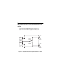
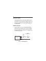
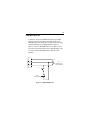
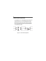
1
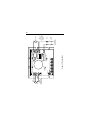
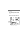
User’s Manual Models: 170-203-0002 170-203-0005 Pulse-Width Modulated, Adjustable Speed Drives for DC Brush Motors Copyright © 2006 by Bison Gear & Engineering All rights reserved. No part of this manual may be reproduced or transmitted in any form without written permission from Bison Gear & Engineering. The information and technical data in this manual are subject to change without notice. Bison Gear & Engineering and its Divisions make no warranty of any kind with respect to this material, including, but not limited to, the implied warranties of its merchantability and fitness for a given purpose. Bison Gear & Engineering and its Divisions assume no responsibility for any errors that may appear in this manual and make no commitment to update or to keep current the information in this manual. Printed in the United States of America. i Safety Warnings SHOCK HAZARD AVOID HEAT KEEP DRY AVOID VIBRATION • This symbol denotes an important safety tip or warning. Please read these instructions carefully before performing any of the procedures contained in this manual. • DO NOT INSTALL, REMOVE, OR REWIRE THIS EQUIPMENT WITH POWER APPLIED. Have a qualified electrical technician install, adjust and service this equipment. Follow the National Electrical Code and all other applicable electrical and safety codes, including the provisions of the Occupational Safety and Health Act (OSHA), when installing equipment. • Reduce the chance of an electrical fire, shock, or explosion by proper grounding, over-current protection, thermal protection, and enclosure. Follow sound maintenance procedures. It is possible for a drive to run at full speed as a result of a component failure. Bison strongly recommends the installation of a master switch in the main power input to stop the drive in an emergency. Circuit potentials are at 115 VAC or 230 VAC above earth ground. Avoid direct contact with the printed circuit board or with circuit elements to prevent the risk of serious injury or fatality. Use a non-metallic screwdriver for adjusting the calibration trimpots. Use approved personal protective equipment and insulated tools if working on this drive with power applied. ii Contents Safety Warnings i Specifications 1 Dimensions 2 Installation 3 Mounting . . . . . . . . . . . . . . . . . . . . . . . . . . . . . . . . . . . . . . . . . . . . . . . . . . . . . . .3 Wiring . . . . . . . . . . . . . . . . . . . . . . . . . . . . . . . . . . . . . . . . . . . . . . . . . . . . . . . . . .4 Shielding guidelines . . . . . . . . . . . . . . . . . . . . . . . . . . . . . . . . . . . . . . . . . . . .5 Line fusing . . . . . . . . . . . . . . . . . . . . . . . . . . . . . . . . . . . . . . . . . . . . . . . . . . . . .6 Speed adjust potentiometer . . . . . . . . . . . . . . . . . . . . . . . . . . . . . . . . . . . . . . . . .7 Connections . . . . . . . . . . . . . . . . . . . . . . . . . . . . . . . . . . . . . . . . . . . . . . . . . . . . .8 Power, fuse and motor connections . . . . . . . . . . . . . . . . . . . . . . . . . . . . . . . .8 Master power switch . . . . . . . . . . . . . . . . . . . . . . . . . . . . . . . . . . . . . . . . .8 Motor . . . . . . . . . . . . . . . . . . . . . . . . . . . . . . . . . . . . . . . . . . . . . . . . . . . . .9 Power input . . . . . . . . . . . . . . . . . . . . . . . . . . . . . . . . . . . . . . . . . . . . . . . .9 Line fuse . . . . . . . . . . . . . . . . . . . . . . . . . . . . . . . . . . . . . . . . . . . . . . . . . .9 Voltage Follower . . . . . . . . . . . . . . . . . . . . . . . . . . . . . . . . . . . . . . . . . . . . . . . .11 Operation 12 Before applying power . . . . . . . . . . . . . . . . . . . . . . . . . . . . . . . . . . . . . . . . . .12 Startup . . . . . . . . . . . . . . . . . . . . . . . . . . . . . . . . . . . . . . . . . . . . . . . . . . . . . . . .13 Starting and Stopping Methods . . . . . . . . . . . . . . . . . . . . . . . . . . . . . . . . . . .14 Line starting and line stopping . . . . . . . . . . . . . . . . . . . . . . . . . . . . . . . . . . .14 Automatic restart upon power restoration . . . . . . . . . . . . . . . . . . . . . . . . . .15 Inhibit terminals . . . . . . . . . . . . . . . . . . . . . . . . . . . . . . . . . . . . . . . . . . . . . . .15 Inhibit plug . . . . . . . . . . . . . . . . . . . . . . . . . . . . . . . . . . . . . . . . . . . . . . . . . .16 Decelerating to minimum speed . . . . . . . . . . . . . . . . . . . . . . . . . . . . . . . . .17 Dynamic braking . . . . . . . . . . . . . . . . . . . . . . . . . . . . . . . . . . . . . . . . . . . .18 iii RUN/BRAKE switch . . . . . . . . . . . . . . . . . . . . . . . . . . . . . . . . . . . . . . . . .18 Dynamic brake resistor sizes . . . . . . . . . . . . . . . . . . . . . . . . . . . . . . . . .18 Calibration 20 Calibration procedure . . . . . . . . . . . . . . . . . . . . . . . . . . . . . . . . . . . . . . . . . . . .21 Before applying power . . . . . . . . . . . . . . . . . . . . . . . . . . . . . . . . . . . . . . . . .21 MINIMUM SPEED (MIN SPD) . . . . . . . . . . . . . . . . . . . . . . . . . . . . . . . . . . .22 MAXIMUM SPEED (MAX SPD) . . . . . . . . . . . . . . . . . . . . . . . . . . . . . . . . . .22 ACCELERATION (ACCEL) . . . . . . . . . . . . . . . . . . . . . . . . . . . . . . . . . . . . .23 DECELERATION (DECEL) . . . . . . . . . . . . . . . . . . . . . . . . . . . . . . . . . . . . .23 REGULATION (IR COMP) . . . . . . . . . . . . . . . . . . . . . . . . . . . . . . . . . . . . . .24 CURRENT LIMIT (CURR LIM) . . . . . . . . . . . . . . . . . . . . . . . . . . . . . . . . . . .25 Application Notes Multiple fixed speeds 31 . . . . . . . . . . . . . . . . . . . . . . . . . . . . . . . . . . . . . . . . . . . .31 Adjustable speeds using potentiometers in series . . . . . . . . . . . . . . . . . . . . . .32 Independent adjustable speeds . . . . . . . . . . . . . . . . . . . . . . . . . . . . . . . . . . . .33 RUN/JOG switch . . . . . . . . . . . . . . . . . . . . . . . . . . . . . . . . . . . . . . . . . . . . . . . .34 RUN/JOG option #1 . . . . . . . . . . . . . . . . . . . . . . . . . . . . . . . . . . . . . . . . . . .34 RUN/JOG option #2 . . . . . . . . . . . . . . . . . . . . . . . . . . . . . . . . . . . . . . . . . . .35 Leader-follower application . . . . . . . . . . . . . . . . . . . . . . . . . . . . . . . . . . . . . . . .36 Reversing . . . . . . . . . . . . . . . . . . . . . . . . . . . . . . . . . . . . . . . . . . . . . . . . . . . . .37 Troubleshooting 38 Before troubleshooting . . . . . . . . . . . . . . . . . . . . . . . . . . . . . . . . . . . . . . . . . . .38 Diagnostic LEDs . . . . . . . . . . . . . . . . . . . . . . . . . . . . . . . . . . . . . . . . . . . . . . . .39 POWER . . . . . . . . . . . . . . . . . . . . . . . . . . . . . . . . . . . . . . . . . . . . . . . . . . . .39 CURRENT LIMIT (CL/FLT) . . . . . . . . . . . . . . . . . . . . . . . . . . . . . . . . . . . . .39 iv Certificate of Compliance 43 CE Certification . . . . . . . . . . . . . . . . . . . . . . . . . . . . . . . . . . . . . . . . . . . . . . . . .43 AC Line Filters . . . . . . . . . . . . . . . . . . . . . . . . . . . . . . . . . . . . . . . . . . . . . . . . .44 Unconditional Warranty inside back cover v Illustrations Figure Figure Figure Figure Figure Figure Figure Figure Figure Figure Figure Figure Figure Figure Figure Figure Figure Figure Figure Figure Figure 1. 2. 3. 4. 5. 6. 7. 8. 9. Dimensions . . . . . . . . . . . . . . . . . . . . . . . . . . . . . . . . . . . . . . . . . . . . . . .2 Speed Adjust Potentiometer . . . . . . . . . . . . . . . . . . . . . . . . . . . . . . . . . . .7 Connections . . . . . . . . . . . . . . . . . . . . . . . . . . . . . . . . . . . . . . . . . . . . . .10 Voltage Follower Connections . . . . . . . . . . . . . . . . . . . . . . . . . . . . . . . .11 Inhibit Terminal Location . . . . . . . . . . . . . . . . . . . . . . . . . . . . . . . . . . . .16 Run/Decelerate to Minimum Speed Switch . . . . . . . . . . . . . . . . . . . . . .17 Dynamic Brake Connection . . . . . . . . . . . . . . . . . . . . . . . . . . . . . . . . . .19 Calibration Trimpot Layout . . . . . . . . . . . . . . . . . . . . . . . . . . . . . . . . . . .20 Approximate CURRENT LIMIT and IR COMP Settings for 120 VAC in, 90 VDC out (actual settings may vary) . . . . . . . . . . . .27 10. Approximate CURRENT LIMIT and IR COMP Settings for 120 VAC in, 130 VDC out (actual settings may vary) . . . . . . . . . .28 11. Approximate CURRENT LIMIT and IR COMP Settings for 240 VAC in, 180 VDC out (actual settings may vary) . . . . . . . . . . .29 12. Approximate CURRENT LIMIT and IR COMP Settings for 240 VAC in, 240 VDC out (actual settings may vary) . . . . . . . . . .30 13. Multiple Fixed Speeds . . . . . . . . . . . . . . . . . . . . . . . . . . . . . . . . . . . . .31 14. Adjustable Speeds Using Potentiometers In Series . . . . . . . . . . . . . .32 15. Independent Adjustable Speeds . . . . . . . . . . . . . . . . . . . . . . . . . . . . .33 16. RUN/JOG Option #1 . . . . . . . . . . . . . . . . . . . . . . . . . . . . . . . . . . . . . .34 17. RUN/JOG Option #2 . . . . . . . . . . . . . . . . . . . . . . . . . . . . . . . . . . . . . .35 18. Leader-Follower Application . . . . . . . . . . . . . . . . . . . . . . . . . . . . . . . . .36 19. Reversing . . . . . . . . . . . . . . . . . . . . . . . . . . . . . . . . . . . . . . . . . . . . . .37 20. Diagnostic LED locations . . . . . . . . . . . . . . . . . . . . . . . . . . . . . . . . . . .39 21. CE Filter Connections . . . . . . . . . . . . . . . . . . . . . . . . . . . . . . . . . . . . .45 vi Tables Table Table Table Table 1. 2. 3. 4. Recommended Line Fuse Sizes . . . . . . . . . . . . . . . . . . . . . . . . . . . . . . .6 Inhibit Plug Part Numbers . . . . . . . . . . . . . . . . . . . . . . . . . . . . . . . . . . .16 Dynamic Brake Resistor Part Numbers . . . . . . . . . . . . . . . . . . . . . . . . .19 AC Line Filters . . . . . . . . . . . . . . . . . . . . . . . . . . . . . . . . . . . . . . . . . . . .44 1 Specifications Model 170-203-0002 170-203-0005 AC Line Voltage 120 OR 240 120 OR 240 Max. Continuous HP Range Armature with 120 Current VAC (Amps DC) Applied 2 1/20 – 1/4 5 1/4 – 1/2 HP Range with 240 VAC Applied 1/10 – 1/2 1/2 – 1 AC Line Voltage 120/240 VAC ± 10%, 50/60 Hz, single phase Armature Voltage Range 120 VAC input 0-130 VDC 240 VAC input 0 – 240 VDC Form Factor (at base speed) 1.05 Acceleration/Deceleration Time Range (no load) 0.5 – 6 seconds Analog Input Voltage Range* [S1(–) to S2(+)] 0 – 5 VDC Input Impedance (S1 to S2 with 5 VDC input) approximately 70K ohms Speed Regulation 1% base speed or better Ambient Temp. Range (chassis drive) 10°C – 40°C Vibration 0.5g max (20 – 50 Hz) 0.1 g max (>50 Hz) Weight 170-203-0002 170-203-0005 * Signal must be isolated. 0.66 lb [0.30 kg] 0.72 lb [0.32 kg] 2 Dimensions C505 C504 C503 C502 A1 S3 R501 T501 L2 INHIBIT D Q503 C501 3.64 [92] A2 S2 S1 IL502 CURRENT LIMIT POWER L1 0.19 [5] 1.75 [44] TH501 IL501 CURRENT LIMIT MAX SPD MIN SPD IR COMP DECEL ACCEL 0.70 [18] 3.80 [97] 4.30 [109] A 0.82 [21] 2.10 [53] 0.19 [5] 0.96 [24] MODEL DIMENSION “A” HEIGHT 170-203-0002 170-203-0005 2.50 [62] 3.20 [81] ALL DIMENSIONS IN INCHES [MILLIMETERS] Figure 1. Dimensions 3 Installation Mounting Warning Do not install, rewire, or remove this control with input power applied. Doing so may cause fire or serious injury. Make sure you have read and understood the Safety Warnings before attempting installation. • Drive components are sensitive to electrostatic fields. Avoid direct contact with the circuit board. Hold drive by the chassis only. • Protect the drive from dirt, moisture, and accidental contact. • Provide sufficient room for access to the terminal block and calibration trimpots. • Mount the drive away from heat sources. Operate the drive within the specified ambient operating temperature range. • Prevent loose connections by avoiding excessive vibration of the drive. • Mount drive with its board in either a horizontal or vertical plane. Six 0.19 in. (5 mm) wide slots in the chassis accept #8 pan head screws. Fasten either the large base or the narrow flange of the chassis to the subplate. 4 • The chassis must be earth grounded. Use a star washer beneath the head of at least one of the mounting screws to penetrate the anodized chassis surface and to reach bare metal. Wiring Warning Ꮨ Do not install, remove, or rewire this equipment with power applied. Failure to heed this warning may result in fire, explosion, or serious injury. Circuit potentials are at 115 or 230 VAC above ground. To prevent the risk of injury or fatality, avoid direct contact with the printed circuit board or with circuit elements. Do not disconnect any of the motor leads from the drive unless power is removed or the drive is disabled. Opening any one motor lead may destroy the drive. • Use 16–20 AWG wire for speed adjust potentiometer wiring. Use 14–16 AWG wire for AC line (L1, L2) and motor (A1 and A2) wiring. 5 Shielding guidelines Warning Under no circumstances should power and logic leads be bundled together. Induced voltage can cause unpredictable behavior in any electronic device, including motor controls. As a general rule, Bison recommends shielding of all conductors. If it is not practical to shield power conductors, Bison recommends shielding all logic-level leads. If shielding logic leads is not practical, the user should twist all logic leads with themselves to minimize induced noise. It may be necessary to earth ground the shielded cable. If noise is produced by devices other than the drive, ground the shield at the drive end. If noise is generated by a device on the drive, ground the shield at the end away from the drive. Do not ground both ends of the shield. If the drive continues to pick up noise after grounding the shield, it may be necessary to add AC line filtering devices, or to mount the drive in a less noisy environment. Logic wires from other input devices, such as motion controllers and PLL velocity controllers, must be separated from power lines in the same manner as the logic I/O on this drive. 6 Line fusing Protect all Bison drives with AC line fuses. Use fast acting AC line fuses rated for 250 volts, and approximately 150% – 200% of the maximum armature current. Fuse only the “hot” side of the AC line (L1) if using 115 VAC line voltage. Do not add line fuses to L2 unless you use 240 VAC line voltage. See Table 1 below for recommended line fuse sizes: Table 1. Recommended Line Fuse Sizes Maximum Armature AC Line Fuse Current (DC Amps) Rating (AC Amps) 1.5 and below 3 2.6 5 3.5 8 5.0 10 7 Speed adjust potentiometer Warning Be sure that the potentiometer tabs do not make contact with the potentiometer enclosure. Grounding the input will cause damage to the drive. Mount the speed adjust potentiometer through a 0.38 in. (10 mm) hole with the hardware provided (Figure 2). Install the circular insulating disk between the panel and the 10K ohm speed adjust potentiometer. Twist the speed adjust potentiometer wire to avoid picking up unwanted electrical noise. If speed adjust potentiometer wires are longer than 18 in. (457 mm), use shielded cable. Keep speed adjust potentiometer wires separate from power leads (L1, L2, A1, A2). MOUNT THROUGH A 0.38 IN. (10 MM) HOLE CW WIPER CCW NUT STAR WASHER SPEED ADJUST POTENTIOMETER INSULATING DISK POT TAB ASSIGNMENTS PANEL Figure 2. Speed Adjust Potentiometer 8 Connections Warning Do not connect this equipment with power applied. Failure to heed this directive may result in fire or serious injury. Bison strongly recommends the installation of a master power switch in the voltage input line, as shown in Figure 3 (page 10). The switch contacts should be rated at a minimum of 200% of motor nameplate current and 250 volts. Power, fuse and motor connections Connect the power input leads, an external line fuse and a DC motor to the drive’s printed circuit board (PCB) as shown in Figure 3, page 10. Master power switch Decelerating to minimum speed or coasting to a stop may not stop a drive that is malfunctioning. Removing AC line power (both L1 and L2) is the only acceptable method for emergency stopping. For this reason, Bison strongly recommends installing an emergency stop switch on both the L1 and L2 inputs. The switch contacts must be rated at a minimum of 250 volts and 200% of maximum drive current. 9 Motor Bison drives supply motor voltage from A1 and A2 terminals. It is assumed throughout this manual that, when A1 is positive with respect to A2 , the motor will rotate clockwise (CW) while looking at the output shaft protruding from the front of the motor. If this is opposite of the desired rotation, simply reverse the wiring of A1 and A2 with each other. Connect a DC motor to PCB terminals A1 and A2 as shown in Figure 3. Ensure that the motor voltage rating is consistent with the drive’s output voltage. Power input Connect the AC line power leads to PCB terminals L1 and L2, or to a double-throw, single-pole master power switch (recommended). Line fuse Wire an external line fuse between the stop switch (if installed) and the L1 terminal the circuit board. An additional line fuse should be installed on L2 if the input voltage is 230VAC. The line fuse(s) should be rated at 250 volts and 150 - 200% of maximum motor nameplate current. Refer to the line fuse chart on page 6 for fuse ratings. 10K OHM SPEED ADJUST POTENTIOMETER CW INHIBIT IL502 C504 C501 DECEL C502 ACCEL POWER C505 C503 TH501 IL501 R501 Figure 3. Connections MIN SPD IR COMP CURRENT LIMIT CURRENT LIMIT S2 S1 S3 D L1 L2 A2 A1 MOTOR FUSE STOP SWITCH 120/240 VAC LINE VOLTAGE * * NOTE: FUSE L2 ONLY IF LINE VOLTAGE IS 240 VAC. + 10 T501 11 Voltage follower Instead of using a speed adjust potentiometer, the drive may be wired to follow a 0 – 5 VDC isolated voltage signal (Figure 4). Connect the signal return (–) to S1. Connect the signal high or (+) to S2. Make no connection to S3. A potentiometer can be used to scale the analog input voltage. 0 - 5 VDC VOLTAGE SIGNAL C505 C C502 REF (+) R501 C504 S2 S1 C501 INHIBIT COM (-) IL502 CURRENT LIMIT POWER CURRENT LIMIT MAX SPD MIN SPD IR COMP Figure 4. Voltage Follower Connections DECEL ACCEL TH50 IL50 12 Operation Warning Ꮨ Dangerous voltages exist on the drive when it is powered, and up to 30 seconds after power is removed and the motor stops. BE ALERT. High voltages can cause serious or fatal injury. For your safety, use personal protective equipment (PPE) when operating this drive. If the motor or drive does not perform as described, disconnect the AC line voltage immediately. Refer to the Troubleshooting section on page 38 for further assistance. Before applying power • Verify that no conductive material is present on the printed circuit board. 13 Startup To start the drive: 1. Turn the speed adjust potentiometer full counterclockwise (CCW). If the drive is following a voltage signal, set the voltage signal to 0 VDC. 2. Apply AC line voltage. 3. Slowly advance the speed adjust potentiometer clockwise (CW). If the drive is following a voltage signal, slowly increase the voltage signal. The motor slowly accelerates as the potentiometer is turned CW, or the voltage signal is increased. Continue until the desired speed is reached. 4. Remove AC line voltage from the drive to coast the motor to a stop. 14 Starting and Stopping Methods Warning Decelerating to minimum speed or coasting to a stop is recommended for frequent starts and stops. Do not use any of these methods for emergency stopping. They may not stop a drive that is malfunctioning. Removing AC line power (both L1 and L2) is the only acceptable method for emergency stopping. For this reason, Bison strongly recommends installing an emergency stop switch on both the L1 and L2 inputs (see Connections on page 10). Line starting and line stopping Line starting and line stopping (applying and removing AC line voltage) is recommended for infrequent starting and stopping of a drive only. When AC line voltage is applied to the drive, the motor accelerates to the speed set by the speed adjust potentiometer. When AC line voltage is removed, the motor coasts to a stop. 15 Automatic restart upon power restoration All drives automatically run to set speed when power is applied and the drive is enabled. The drive will accelerate at a rate controlled by the ACCEL trimpot. Refer to the Calibration section for information on adjusting this setting. Inhibit terminals Warning Inhibit is used for frequent starts and stops. It must never be used as an emergency stop because it may not stop a drive that is malfunctioning. Removing AC power (L1 and L2) is the only acceptable method for emergency stopping. Jumper the inhibit terminals to coast the motor to a stop (Figure 5). Remove the jumper to accelerate the motor to set speed. 16 Inhibit plug Bison offers an accessory plug harness for use with the inhibit terminals: Table 2. Inhibit Plug Part Numbers Bison® Part Number 170-998-0100 Description Inhibit plug with 36-in. (91 cm) wires Twist inhibit plug wires and separate them from other powercarrying wires or sources of electrical noise. Use shielded cable if the inhibit plug wires are longer than 18 inches (46 cm). If shielded cable is used, ground only one end of the shield to earth ground. Do not ground both ends of the shield. INHIBIT TERMINAL C505 C503 C502 R501 C504 IL502 CURRENT Figure 5. Inhibit Terminal Location D Q503 C501 INHIBIT T501 S2 S1 17 Decelerating to minimum speed A switch may be used to decelerate the motor to minimum speed. Connect the switch as shown in Figure 6. Close the switch between S1 and S2 to decelerate the motor from set speed. Open the switch to accelerate the motor to set speed. The ACCEL and DECEL trimpot settings determine the rate at which the motor accelerates and decelerates, respectively. CW S3 10K OHM SPEED ADJUST POTENTIOMETER S2 S1 RUN DECEL TO MIN SPEED Figure 6. Run/Decelerate to Minimum Speed Switch 18 Dynamic braking Warning Wait for the motor to come to a complete stop before setting the RUN/BRAKE switch to RUN. This will prevent high armature currents from damaging the motor or drive. Dynamic braking may be used to rapidly stop a motor (see Figure 7 on page 19). For the RUN/BRAKE switch, use a doublepole, double throw switch rated for at least the maximum DC armature voltage and maximum braking current. RUN/BRAKE switch Install a double-pole, double-throw switch between the INHIBIT terminals and a dynamic brake resistor as shown in Figure 7 on page 19. Set the switch to the BRAKE position to dynamically brake the motor to a stop. Set the switch to the RUN position to accelerate the motor to set speed at a rate controlled by the ACCEL trimpot. Dynamic brake resistor sizes Size the dynamic brake resistor according to the motor current rating (refer to Table 3 on page 19). The dynamic brake resistance listed in the table is the smallest recommended resistance allowed to prevent possible demagnetization of the motor. The motor stops less rapidly with higher brake resistor values. 19 Table 3. Dynamic Brake Resistor Part Numbers Minimum Motor Armature Current Rating Less than 2 ADC 2–3 ADC 3–5 ADC 5–10 ADC Minimum Dynamic Brake Resistor Value 1 ohm 5 ohm 10 ohm 20 ohm Dynamic Brake Resistor Wattage 1W 5W 10W 20W For motors rated 1/17 horsepower and lower, a brake resistor is not necessary since the armature resistance is high enough to stop the motor without demagnetization. Replace the dynamic brake with 12 gauge wire. A1 A2 RUN MOTOR DYNAMIC BRAKE RESISTOR BRAKE INHIBIT Figure 7. Dynamic Brake Connection 20 Calibration Each drive is factory calibrated to its maximum current rating. Readjust the calibration trimpot settings to accommodate lower current motors. All adjustments increase with CW rotation, and decrease with CCW rotation. Use a non-metallic screwdriver for calibration. Each trimpot is identified on the printed circuit board. A1 R501 C502 S2 S1 INHIBIT T501 A2 L2 Q503 C501 D L1 IL502 CURRENT LIMIT POWER TH501 IL501 CURRENT LIMIT CURRENT LIMIT MAX SPD MIN SPD IR COMP MAX SPEED MIN SPEED IR COMP DECEL ACCEL DECELERATION Figure 8. Calibration Trimpot Layout ACCELERATION 21 Calibration procedure Before applying power 1. Verify that no conductive material is present on the printed circuit board. 2. Set all trimpots full except CURRENT LIMIT full counterclockwise (CCW). 3. Set the CURRENT LIMIT trimpot full clockwise (CW). 4. Set the speed adjust potentiometer or input signal to zero speed. 5. Set the INHIBIT switch to INHIBIT, or install the jumper between the INHIBIT terminals of SO501. 6. Apply line voltage to the drive. The green POWER LED shall light, but the motor should remain stopped. 7. Set the INHIBIT switch to ENABLE, or remove the jumper between the INHIBIT terminals of SO501. 22 MINIMUM SPEED (MIN SPD) MIN SPD determines the minimum speed when the speed adjust potentiometer is turned full CCW. It is factory set to zero speed. To calibrate MIN SPD: 1. Set the speed adjust potentiometer full CCW. 2. Adjust the MIN SPD trimpot until the motor turns at the desired minimum speed. MAXIMUM SPEED (MAX SPD) The MAX SPD setting determines the maximum motor speed when the speed adjust potentiometer is turned full CW. It is factory set for maximum rated motor speed. To calibrate MAX SPD: 1. Set the MAX trimpot full CCW. 2. Turn the speed adjust potentiometer full CW. 3. Adjust the MAX SPD trimpot until the desired maximum motor speed is reached. 23 ACCELERATION (ACCEL) The ACCELERATE setting determines the time the motor takes to ramp to a higher speed. See Specifications on page 1 for approximate acceleration times. The ACCELERATE setting is factory set to its minimum value (full CCW). Turn the ACCEL trimpot CW to increase the acceleration time and CCW to decrease the acceleration time. DECELERATION (DECEL) The DECELERATE setting determines the time the motor takes to ramp to a lower speed. See Specifications on page 1 for approximate deceleration times. The DECELERATE setting is factory set to its minimum value (full CCW). Turn the DECEL trimpot CW to increase the deceleration time and CCW to decrease the deceleration time. 24 REGULATION (IR COMP) The IR COMP setting determines the degree to which motor speed is held constant as the motor load changes. It is factory set for optimum motor regulation. Recalibrate the IR COMP setting when using a lower current rated motor. Refer to Figures 9 - 12 (pp 27 30) for typical IR COMP settings, or recalibrate using the following procedure: If the motor does not maintain set speed as the load changes, gradually rotate the IR COMP trimpot CW. If the motor oscillates (overcompensation), the IR COMP trimpot may be set too high (CW). Turn the IR COMP trimpot CCW to stabilize the drive. 25 CURRENT LIMIT (CURR LIM) Warning Although the current limit trimpot can be set to exceed the motor's maximum armature current rating, Bison recommends you do not run the motor continuously beyond that rating. Continuous operation beyond the maximum armature current rating may cause thermal degradation of the motor and drive. The CURRENT LIMIT setting determines the maximum torque for accelerating and driving the motor. CURRENT LIMIT is factory set at 120% of maximum drive current. You must recalibrate the CURRENT LIMIT setting if using a lower current rated motor. Refer to Figures 9 - 12 (pp 27 - 30) for typical CURRENT LIMIT settings. 1. With no power applied to the drive, connect a DC ammeter in series with the motor armature. 2. Set the CURRENT LIMIT trimpot to full CCW. 3. Carefully lock the motor armature. Ensure that the motor is firmly mounted. 4. Apply line power. The motor should be stopped. 5. Set the speed potentiometer or reference signal to maximum speed. The motor should remain stopped. 26 CURRENT LIMIT (cont.) 6. Slowly rotate the CURRENT LIMIT trimpot clockwise (CW) until the ammeter reads 120% of maximum motor armature current. 7. Set the speed adjust potentiometer or reference signal to zero speed. 8. Remove power from the drive. 9. Remove the lock from the motor shaft. 10. Remove the ammeter in series with the motor armature. 27 170-203-0002 MOTOR HP: VOLTS RPM: AMPS: 1/4 90 VDC 1750 2.5 ADC 170-203-0005 MOTOR HP: VOLTS RPM: AMPS: CURR LIM I/R COMP CURR LIM I/R COMP I/R COMP CURR LIM I/R COMP CURR LIM I/R COMP 1/3 90 VDC 1750 3.5 ADC MOTOR HP: VOLTS RPM: AMPS: CURR LIM 1/2 90 VDC 1750 5.0 ADC MOTOR HP: VOLTS RPM: AMPS: 1/8 90 VDC 1750 1.3 ADC MOTOR HP: VOLTS RPM: AMPS: I/R COMP 1/20 90 VDC 1750 0.5 ADC MOTOR HP: VOLTS RPM: AMPS: CURR LIM 1/4 90 VDC 1750 2.7 ADC Figure 9. Approximate CURRENT LIMIT and IR COMP Settings for 120 VAC in, 90 VDC out (actual settings may vary) 28 170-203-0002 MOTOR CURR LIM 170-203-0005 I/R COMP MOTOR CURR LIM I/R COMP 1/4 HP: VOLTS: 130 VDC RPM: 2500 AMPS: 1.8 ADC CURR LIM I/R COMP MOTOR CURR LIM I/R COMP CURR LIM I/R COMP 1/3 HP: VOLTS: 130 VDC RPM: 2500 AMPS: 2.6 ADC 1/8 HP: VOLTS: 130 VDC RPM: 2500 AMPS: 1.0 ADC MOTOR MOTOR 1/2 HP: VOLTS: 130 VDC RPM: 2500 AMPS: 3.8 ADC 1/20 HP: VOLTS: 130 VDC RPM: 2500 AMPS: 0.4 ADC CURR LIM I/R COMP MOTOR 1/4 HP: VOLTS: 130 VDC RPM: 2500 AMPS: 2.0 ADC Figure 10. Approximate CURRENT LIMIT and IR COMP Settings for 120 VAC in, 130 VDC out (actual settings may vary) 29 170-203-0002 MOTOR CURR LIM 170-203-0005 I/R COMP HP: 1/2 VOLTS: 180 VDC RPM: 1750 AMPS: 1.4 ADC MOTOR MOTOR CURR LIM I/R COMP CURR LIM I/R COMP CURR LIM I/R COMP HP: 1 VOLTS: 180 VDC RPM: 1750 AMPS: 5.0 ADC CURR LIM I/R COMP HP: 1/4 VOLTS: 180 VDC RPM: 1750 AMPS: 1.0 ADC HP: 1/8 VOLTS: 180 VDC RPM: 1750 AMPS: 0.6 ADC MOTOR MOTOR HP: 3/4 VOLTS: 180 VDC RPM: 1750 AMPS: 3.5 ADC CURR LIM I/R COMP MOTOR HP: 1/2 VOLTS: 180 VDC RPM: 1750 AMPS: 2.7 ADC Figure 11. Approximate CURRENT LIMIT and IR COMP Settings for 240 VAC in, 180 VDC out (actual settings may vary) 30 170-203-0002 MOTOR CURR LIM 170-203-0005 I/R COMP CURR LIM I/R COMP MOTOR I/R COMP MOTOR CURR LIM I/R COMP CURR LIM I/R COMP 3/4 HP: VOLTS: 240 VDC RPM: 2500 AMPS: 2.7 ADC 1/3 HP: VOLTS: 240 VDC RPM: 2500 AMPS: 1.0 ADC 1/4 HP: VOLTS: 240 VDC RPM: 2500 AMPS: 0.75 ADC CURR LIM 1 HP: VOLTS: 180 VDC RPM: 1750 AMPS: 5.0 ADC 1/2 HP: VOLTS: 240 VDC RPM: 2500 AMPS: 1.9 ADC MOTOR MOTOR CURR LIM I/R COMP MOTOR 1/2 HP: VOLTS: 240 VDC RPM: 2500 AMPS: 2.0 ADC Figure 12. Approximate CURRENT LIMIT and IR COMP Settings for 240 VAC in, 240 VDC out (actual settings may vary) 31 Application Notes Multiple fixed speeds Replace the speed adjust potentiometer with series resistors having a total series resistance of 10 K ohms (Figure 13). Add a single pole, multi-position switch with the correct number of positions for the desired number of fixed speeds. R1 S3 R2 S2 R3 S1 TOTAL SERIES RESISTANCE 10K OHMS R4 Figure 13. Multiple Fixed Speeds 32 Adjustable speeds using potentiometers in series Connect two speed adjust potentiometers as shown in Figure 14 to select between high speed and low speed. CW S3 HIGH SPEED 5K OHM LOW SPEED CW S2 S1 5K OHM Figure 14. Adjustable Speeds Using Potentiometers In Series 33 Independent adjustable speeds Connect two speed adjust potentiometers with a single-pole, multiposition switch and two or more potentiometers in parallel, with a total resistance of 10K ohms. Figure 15 shows the connection of two independent speed adjust potentiometers that can be mounted at two separate operating stations. S3 SPEED 2 CW CW SPEED 1 20K OHM 20K OHM S2 S1 Figure 15. Independent Adjustable Speeds 34 RUN/JOG switch Using a RUN/JOG switch is recommended in applications where quick stopping is not needed and frequent jogging is required. Use a single pole, two position switch for the RUN/JOG switch, and a single-pole, normally-closed, momentary operated pushbutton for the JOG pushbutton. RUN/JOG option #1 In option #1 (Figure 16), connect the RUN/JOG switch and the JOG pushbutton to the INHIBIT terminals. When the RUN/JOG switch is set to JOG, the motor coasts to minimum speed. Press the JOG pushbutton to jog the motor. Return the RUN/JOG switch to RUN for normal operation. RUN INHIBIT JOG PUSHBUTTON JOG Figure 16. RUN/JOG Option #1 35 RUN/JOG option #2 In option #2, connect the RUN/JOG switch to the speed adjust potentiometer using a single-pole, two-position switch for the RUN/JOG switch, and a single-pole, normally-closed, momentary operated pushbutton for the JOG pushbutton as shown in Figure 17. When the RUN/JOG switch is set to JOG, the motor decelerates to minimum speed. Press the JOG pushbutton to jog the motor. Return the RUN/JOG switch to RUN for normal operation. S3 CW S2 10K OHM SPEED ADJUST POTENTIOMETER S1 RUN JOG JOG PUSHBUTTON Figure 17. RUN/JOG Option #2 36 Leader-follower application In this application, use a 170-993-0200 to monitor the speed of the leader motor (Figure 18). The 170-993-0200 outputs a voltage proportional to the leader motor armature voltage. The follower drive uses this voltage reference to set the speed of the follower motor. An optional ratio potentiometer may be used to scale the 170-993-0200 output voltage. MOTOR A2 (+) 2 9 (+) A1 Leader Drive 8 170-993-0200 7 (-) TB501 S2 (-) 1 TB502 S1 10K Ohm (optional) Figure 18. Leader-Follower Application Follower Drive 37 Reversing A dynamic brake may be used when reversing the motor direction (Figure 19). Use a three-pole, three-position switch rated for at least the maximum DC armature voltage and maximum braking current. Wait for the motor to stop completely before switching it to either the forward or reverse direction. See the Dynamic braking section on page 18 for sizing the dynamic brake resistor. A1 A2 DYNAMIC BRAKE RESISTOR MOTOR FWD BRAKE REV INHIBIT Figure 19. Reversing 38 Troubleshooting Warning Dangerous voltages exist on the drive when it is powered, and up to 30 seconds after power is removed. When possible, disconnect the drive while troubleshooting. High voltages can cause serious or fatal injury. Before troubleshooting Perform the following steps before starting any procedure in this section: • Disconnect AC line voltage from the drive. • Check the drive closely for damaged components. • Check that no conductive or other foreign material has become lodged on the printed circuit board. • Verify that every connection is correct and in good condition. • Verify that there are no short circuits or grounded connections. • Check that the voltage selection switch settings match the AC line and output voltages. • Check that the drive's rated armature and field outputs are consistent with the motor ratings. For additional assistance, contact your local Bison distributor, or the factory direct: Phone: 1-800-AT-BISON 39 Diagnostic LEDs This series of drives are equipped with the following diagnostic LEDs to aid in troubleshooting or monitoring equipment status. Refer to Figure 20 below. POWER Green LED lights when AC line voltage is applied to the drive. CURRENT LIMIT (CL/FLT) Red LED lights when drive output current exceeds the threshold set by the CURRENT LIMIT trimpot. L2 2 INHIBIT T501 A2 2 S2 S1 L1 Q503 C501 D IL502 CURRENT LIMIT POWER TH501 IL501 CURRENT LIMIT MAX SPD MIN I SPD IR COMP DECEL ACCEL CURRENT LIMIT LED Figure 20. Diagnostic LED locations POWER LED 40 Symptom Line fuse blows Line fuse does not blow, but the motor does not run Possible Causes Suggested Solutions 1. Line fuses are the wrong size. 1. Check that line fuses are the proper size. 2. Motor cable or armature is shorted to ground. 2. Check motor cable and armature for shorts. 3. Nuisance tripping caused by a combination of ambient conditions and highcurrent spikes. 3. Add a blower to cool the drive components; decrease CURRENT LIMIT settings, or resize motor and drive for actual load demand, or check for incorrectly aligned mechanical components or “jams”. See page 25 for information on adjusting the CURRENT LIMIT trimpot. 1. Reference signal or speed adjust pot is set to zero speed. 1. Increase reference signal or speed adjust potentiometer setting. 2. Reference signal or speed adjust potentiometer connections are open. 2. Check that the reference signal or speed adjust potentiometer connections are not open. 41 Symptom Line fuse does not blow, but the motor does not run (cont.) Possible Causes Suggested Solutions 3. Drive is overloaded. 3. Verify that the motor is not jammed. Increase CURRENT LIMIT setting (page 25). 4. Drive is not receiving AC line voltage. 4. Apply AC line voltage to L1 and L2. 5. Motor is not connected. 5. Connect motor to A1 and A2. Motor runs too fast at maximum speed setting 1. MIN SPD and MAX SPD settings are too high. 1. Recalibrate MIN SPD (page 22) and MAX SPD (page 22). Motor runs too slow or too fast 1. MIN SPD and MAX SPD are not calibrated. 1. Recalibrate MIN SPD (page 22) and MAX SPD (page 22). Motor will not reach the desired speed. 1. MAX SPD setting is too low. 1. Increase MAX SPD setting (page 22). 2. IR COMP setting is too low. 2. Increase IR COMP setting (page 24). 3. Motor is overloaded. 3. Check motor load. Resize the motor if necessary. 42 Symptom Motor pulsates or surges under load Possible Causes Suggested Solutions 1. IR COMP is set too high. 1. Adjust the IR COMP setting slightly CCW until the motor speed stabilizes (page 24). 2. Control is in current limit mode. 2. Check that motor and drive are of sufficient horsepower and amperage. You may need to replace the motor and/or the drive. 43 Certificate of Compliance CE Certification Bison hereby certifies that this series of drives have been approved to bear the CE" mark provided the conditions of approval have been met by the end user. The OEM must meet the following conditions: • All wires, including logic, AC power and motor leads, must be shielded. Do not ground both ends of the shield. • This series motor control module must be enclosed in a solid metal enclosure. The enclosure lid, body and backplane must all be tied to a low-impedance earth ground. • A VV-series Corcom© filter (or equivalent) must be wired into the AC main. (See Table 4 on page 44.) • The ground connection between the shielded cable, installed line filter and metal enclosure must be wired to solid earth ground (resistance less than 500 ohms), not machine ground. This is very important! 44 Compliance allows this series to bear the CE mark. The end user, as described herein, falls into one of two categories: 1. The Consumer will deploy a stand-alone unit as an integral, yet external, portion of the machine being operated. 2. The Original Equipment Manufacturer (OEM) will implement the product as a component of the machine being manufactured. AC Line Filters In addition to EMI/RFI safeguards inherent in this series' design, external filtering is required. To meet CE approval conditions, use the line filters (or equivalent) listed in Table 4. Connect the filter as shown in Figure 24. Table 4. AC Line Filters Drive 170-203-0002 170-203-0005 AC Current 3A 7A Corcom Filter 6VV1 10VV1 45 VV1 FILTER DRIVE L1 L1 L2 L2 DRIVE ENCLOSURE GND SCREW SOLID EARTH GROUND Figure 21. CE Filter Connections 46 NOTES 47 NOTES 48 NOTES 49 NOTES 50 NOTES Bison Warranty Policy The Company warrants to the Buyer the products sold hereunder to be free of defects in material and workmanship under normal use and service for a period of one (1) year from the date of shipment. The obligation of the Company under this warranty is limited to repair or replacing at its option, any part or parts, which upon examination shall disclose to the reasonable satisfaction of the Company to have been defective in material or workmanship. Buyer must return the products to the Company’s factory, shipping charges prepaid, and with complete information as to alleged defects and the installation, operation and service of the products. Except as otherwise expressly stated herein the Company makes no representation of warranty of any kind, express or implied, as to merchantability, fitness for a particular purpose, or any other matter with respect to the products sold hereunder. Bison Gear & Engineering Corp. 3850 Ohio Ave. -- St. Charles, IL 60174 Phone: 1-800-AT-BISON www.bisongear.com Document Number: 250-0417; Revision 0 -- May 2006