1
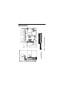
USER’S MANUAL 170-503-0002 Variable-frequency drives for 3-phase and single-phase AC motors Copyright © 2006 by Bison Gear & Engineering All rights reserved. No part of this manual may be reproduced or transmitted in any form without written permission from Bison Gear & Engineering. The information and technical data in this manual are subject to change without notice. Bison Gear & Engineering and its Divisions make no warranty of any kind with respect to this material, including, but not limited to, the implied warranties of its merchantability and fitness for a given purpose. Bison Gear & Engineering and its Divisions assume no responsibility for any errors that may appear in this manual and make no commitment to update or to keep current the information in this manual. MVD082602 Printed in the United States of America. i Safety Warnings • This symbol denotes an important safety tip or SHOCK HAZARD AVOID HEAT KEEP DRY AVOID VIBRATION warning. Please read these instructions carefully before performing any of the procedures contained in this manual. • DO NOT INSTALL, REMOVE, OR REWIRE THIS EQUIPMENT WITH POWER APPLIED. Have a qualified electrical technician install, adjust and service this equipment. Follow the National Electrical Code and all other applicable electrical and safety codes, including the provisions of the Occupational Safety and Health Act (OSHA), when installing equipment. • Reduce the chance of an electrical fire, shock, or explosion by using proper grounding, over-current protection, thermal protection, and enclosure. Follow sound maintenance procedures. It is possible for a drive to run at full speed as a result of a component failure. Bison strongly recommends the installation of a master switch in the main power input to stop the drive in an emergency. Circuit potentials are at 115 VAC or 230 VAC above earth ground. Avoid direct contact with the printed circuit board or with circuit elements to prevent the risk of serious injury or fatality. Use a non-metallic screwdiver for adjusting the calibration trimpots. Use approved personal protective equipment and insulated tools if working on this drive with power applied. ii General Information The Bison 170-503-0002 is a solid-state, variable-frequency AC motor drive. The 170-503-0002 utilizes a 115 or 230 VAC, 50/60 Hz, single-phase input, and is factory calibrated for an output of 0 to 60 Hz. They will operate any 2.4 Amp or smaller, 208/230-volt, three-phase-AC-induction, singlephase permanent split capacitor motor (see page iv) and can be user calibrated for 0 through 120 Hz output. Although 170-503-0002 inverters can operate over their full speed range, most motors will operate with constant torque over a 10:1 speed range, 6 Hz to 60 Hz, and constant horsepower above 60 Hz. (Inverter-duty motors may operate satisfactorily over a 20:1 speed range.) Some motors can be satisfactorily operated at speeds as low as 50 rpm (speed range 50:1). Below 50 rpm, some motors may show signs of “stepping” or “cogging”, and may run warmer. *Although the 170-503-0002 will allow a minimum of 0 Hz, the actual minimum frequency is dependent on motor type and load. The motor may need to be derated for low-frequency (30 Hz and lower) operation. Please consult the motor manufacturer. iii Many 3-phase inverter manufacturers claim that they can run single-phase motors effectively. This is normally accomplished by wiring only 2 phases; however, this method may cause instabilities due to the lack of feedback from one of the motor connections. Furthermore, motor torque will be reduced considerably because the phases are 120° apart. Although the 170-503-0002 uses this method of connection, its fundamental design enables it to operate efficiently under these conditions. This Series features solid-state reversing with adjustable acceleration and deceleration. The 170-503-0002 may also interface with motor thermal protection through the enable circuit. iv Important Information Warning Caution should be taken when operating fan-cooled motors at low speeds because their fans may not move sufficient air to properly cool the motor. Bison recommends “inverter-duty” motors when the speed range is beyond 10:1. In addition to standard 3-phase induction motors, the following motor types may be used with the 170-503-0002: • Permanent split capacitor (PSC) • Shaded pole • AC synchronous The following motor types MAY NOT be used: • • • • • Split phase Capacitor start Repulsion induction Series Universal AC/DC Any motor with starting switch (centrifugal or relay) and/or separate starting winding. v Contents Safety Warnings i General Information ii Important Information iv Specifications 1 Dimensions 2 Installation 3 Mounting . . . . . . . . . . . . . . . . . . . . . . . . . . . . . . . . . . . . . . . . . . . . . . . . . . . . . . .3 Wiring . . . . . . . . . . . . . . . . . . . . . . . . . . . . . . . . . . . . . . . . . . . . . . . . . . . . . . . . . .5 Shielding guidelines . . . . . . . . . . . . . . . . . . . . . . . . . . . . . . . . . . . . . . . . . . . .6 Fusing . . . . . . . . . . . . . . . . . . . . . . . . . . . . . . . . . . . . . . . . . . . . . . . . . . . . . . . . .7 Speed adjust potentiometer . . . . . . . . . . . . . . . . . . . . . . . . . . . . . . . . . . . . . . . . .8 Connections . . . . . . . . . . . . . . . . . . . . . . . . . . . . . . . . . . . . . . . . . . . . . . . . . . . . .9 Power and fuse connections . . . . . . . . . . . . . . . . . . . . . . . . . . . . . . . . . . . . .9 Motor connections . . . . . . . . . . . . . . . . . . . . . . . . . . . . . . . . . . . . . . . . . . . . .13 Single-Phase Operation . . . . . . . . . . . . . . . . . . . . . . . . . . . . . . . . . . . . . .13 Three-Phase Operation . . . . . . . . . . . . . . . . . . . . . . . . . . . . . . . . . . . . . .13 Speed Adjust Potentiometer Connections . . . . . . . . . . . . . . . . . . . . . . . . . .17 Voltage Follower Connections . . . . . . . . . . . . . . . . . . . . . . . . . . . . . . . . . . .18 Signal and Optional Switch Connections . . . . . . . . . . . . . . . . . . . . . . . . . . .19 Operation 21 Voltage Doubler . . . . . . . . . . . . . . . . . . . . . . . . . . . . . . . . . . . . . . . . . . . . . . . . .22 Startup . . . . . . . . . . . . . . . . . . . . . . . . . . . . . . . . . . . . . . . . . . . . . . . . . . . . . . . .23 To reverse motor direction: . . . . . . . . . . . . . . . . . . . . . . . . . . . . . . . . . . . . .24 Starting and stopping methods . . . . . . . . . . . . . . . . . . . . . . . . . . . . . . . . . . . . .25 To coast the motor to a stop . . . . . . . . . . . . . . . . . . . . . . . . . . . . . . . . . . . .25 Thermal protection of the motor . . . . . . . . . . . . . . . . . . . . . . . . . . . . . . . . . .25 Line starting and line stopping . . . . . . . . . . . . . . . . . . . . . . . . . . . . . . . . . . .27 vi Calibration 28 Calibration Procedure Setup for 60 Hz Motors: . . . . . . . . . . . . . . . . . . . . . . . .30 MAXIMUM SPEED (MAX SPD) . . . . . . . . . . . . . . . . . . . . . . . . . . . . . . . . . .30 TORQUE LIMIT (TQ LIMIT) . . . . . . . . . . . . . . . . . . . . . . . . . . . . . . . . . . . . .31 ACCELERATION (ACCEL) . . . . . . . . . . . . . . . . . . . . . . . . . . . . . . . . . . . . .32 DECELERATION (DECEL) . . . . . . . . . . . . . . . . . . . . . . . . . . . . . . . . . . . . .32 BOOST . . . . . . . . . . . . . . . . . . . . . . . . . . . . . . . . . . . . . . . . . . . . . . . . . . . . .33 Calibration Procedure Conclusion . . . . . . . . . . . . . . . . . . . . . . . . . . . . . . . .34 Application Notes 35 Independent adjustable speeds with DIR switch . . . . . . . . . . . . . . . . . . . . . . .35 RUN/JOG switch . . . . . . . . . . . . . . . . . . . . . . . . . . . . . . . . . . . . . . . . . . . . . . . .36 Single speed potentiometer control of multiple motors . . . . . . . . . . . . . . . . . . .37 Quick Reversing . . . . . . . . . . . . . . . . . . . . . . . . . . . . . . . . . . . . . . . . . . . . . . . . .38 Troubleshooting 39 Before troubleshooting . . . . . . . . . . . . . . . . . . . . . . . . . . . . . . . . . . . . . . . . . . .39 Diagnostic LEDs . . . . . . . . . . . . . . . . . . . . . . . . . . . . . . . . . . . . . . . . . . . . . . . .41 POWER LED . . . . . . . . . . . . . . . . . . . . . . . . . . . . . . . . . . . . . . . . . . . . . . . .41 FAULT LED . . . . . . . . . . . . . . . . . . . . . . . . . . . . . . . . . . . . . . . . . . . . . . . . .41 TQ LIMIT LED . . . . . . . . . . . . . . . . . . . . . . . . . . . . . . . . . . . . . . . . . . . . . . .42 Unconditional Warranty inside back cover Tables Table 1. Line Fusing Chart . . . . . . . . . . . . . . . . . . . . . . . . . . . . . . . . . . . . . . . . . . . . . . . . . . . . . .7 vii Illustrations Figure Figure Figure Figure Figure Figure Figure Figure Figure Figure Figure Figure Figure Figure Figure Figure Figure Figure 1. 2. 3. 4. 5. 170-503-0002 Dimensions . . . . . . . . . . . . . . . . . . . . . . . . . . . . . . . . . . . . . . . . . . . . . . .2 Speed Adjust Potentiometer . . . . . . . . . . . . . . . . . . . . . . . . . . . . . . . . . . . . . . . . . . . . . .8 AC Line and Fuse Connections (Voltage Doubler Mode) . . . . . . . . . . . . . . . . . . . . . .11 AC Line and Fuse Connections (No Voltage Doubler) . . . . . . . . . . . . . . . . . . . . . . . .12 Motor Connections for Single-Phase Operation (Motor With Pre-Wired Capacitor) . . . . . . . . . . . . . . . . . . . . . . . . . . . . . . . . . . . . . . . .14 6. Motor Connections for Single-Phase Operation (Configured for use with DIRECTION switch) . . . . . . . . . . . . . . . . . . . . . . . . . . . . . . .15 7. Motor Connections for Three-Phase Motors . . . . . . . . . . . . . . . . . . . . . . . . . . . . . . . .16 8. Speed Adjust Potentiometer Connections to TB501 . . . . . . . . . . . . . . . . . . . . . . . . . .17 9. Voltage Follower connections . . . . . . . . . . . . . . . . . . . . . . . . . . . . . . . . . . . . . . . . . . .18 10. Enable / Disable Switch connections to TB501 . . . . . . . . . . . . . . . . . . . . . . . . . . . . .19 11. Signal and Optional Switch Connections . . . . . . . . . . . . . . . . . . . . . . . . . . . . . . . . . .20 12. Thermal Overload Switch with Optional Enable / Disable Switch . . . . . . . . . . . . . . .26 13. 170-503-0002 Series Calibration Trimpot Layout . . . . . . . . . . . . . . . . . . . . . . . . . . .29 14. Independent Adjustable Speeds . . . . . . . . . . . . . . . . . . . . . . . . . . . . . . . . . . . . . . . . .35 15. RUN/JOG Switch . . . . . . . . . . . . . . . . . . . . . . . . . . . . . . . . . . . . . . . . . . . . . . . . . . . .36 16. Single Speed Potentiometer Control of Multiple Motors . . . . . . . . . . . . . . . . . . . . . .37 17. 170-503-0002 Quick Reversing . . . . . . . . . . . . . . . . . . . . . . . . . . . . . . . . . . . . . . . . .38 18. Diagnostic LED locations . . . . . . . . . . . . . . . . . . . . . . . . . . . . . . . . . . . . . . . . . . . . . .42 1 Specifications Drive 170-503-0002 * 1-Phase Input (VAC) *115 / 230 1 or 3-Phase Output (VAC) 230 Max HP ½ Max Continuous Output Current (AC) 2.4 AC Amps In 10 / 7 Connect only 115 VAC line input to the 115 VAC terminals. Application of 230 VAC line input when set for 115 VAC will result in severe damage to the motor and drive, and possible explosion and injury. AC Voltage Input Range 170-503-0002 drives 115/230 VAC ± 10%, 50/60 Hz single phase Standard Carrier Frequency 16 KHz Output Frequency Range 0 – 120 Hz Adjustable Maximum Output Frequency Range 30 – 120 Hz Acceleration Time Range 1 – 12 seconds Deceleration Time Range 1 – 12 seconds Analog Input Voltage Range (signal must be isolated; S1 [-] to S2 [+]) 0 – 5VDC Input Impedance, S1 to S2 ~ 100K ohms Vibration 0.5G max (20 – 50 Hz) 0.1G max (> 50 Hz) Weight 1.2 lb Ambient Operating Temperature Range 10° – 40° C 0.96 [24] H ALL DIMENSIONS IN INCHES [MILLIMETERS] E2 E1 S1 S2 S3 D MAX JMP501 TQ IC502 TQ BOO V C502 TH501 C501 3.02 [76.7] MAX TOTAL HEIGHT (TOP OF CAP TO BOTTOM OF CHASSIS) C510 J501 ACCEL DECEL Figure 1. 170-503-0002 Dimensions 170-503-0002 0.97 [25] 2.72 [69] 3.70 [94] TB501 U 3.80 [97] 4.30 [109] W J501 115V 230V 2.12 [54] 2 Dimensions L2 L1 3 Installation Mounting Warning DO NOT install, rewire, or remove this control with input power applied. Doing so may cause fire or serious injury. Make sure that you read and understand the Safety Warnings before attempting installation. NOTE: Horizontal mouting may require derating the drive. See your Bison representative for more information • It is recommended that the drive be oriented with the chassis vertical for best heat dissipation. Horizontal mounting, while acceptable, may require some thermal derating. • Six 0.19-inch (5 mm) wide slots accept #8 pan head screws. Fasten either the large base or narrow flange of the chassis to the subplate. • Drive components are sensitive to electrostatic fields. Avoid direct contact with the circuit board. Hold the drive by the chassis only. 4 • Protect the drive from dirt, moisture, and accidental contact. Provide sufficient room for access to the terminal block and calibration trimpots. • Mount the drive away from heat sources. Operate the drive within the specified ambient operating temperature range. • Prevent loose connections by avoiding excessive vibration of the drive. • The chassis must be earth grounded. Use a star washer beneath the head of at least one of the mounting screws to penetrate the anodized chassis surface and to reach bare metal. 5 Wiring Warning DO NOT install, rewire, or remove this control with input power applied. Failure to heed this warning may result in fire, explosion, or serious injury. Circuit potentials are at 115 or 230 VAC above ground. To prevent the risk of injury or fatality, avoid direct contact with the printed circuit board or with circuit elements. Do not disconnect any of the motor leads from the drive unless power is removed. Opening any one motor lead may destroy the drive. Use 20 -- 24 AWG wire for speed adjust potentiometer wiring. Use 14 -- 16 AWG wire for AC line (L1, L2) and motor (U, V and W) wiring. 6 Shielding guidelines Warning Under no circumstances should power and logic leads be bundled together. Induced voltage can cause unpredictable behavior in any electronic device, including motor controls. As a general rule, Bison recommends shielding of all conductors. If it is not practical to shield power conductors, Bison recommends shielding all logic-level leads. If shielding the logic leads is not practical, the user should twist all logic leads with themselves to minimize induced noise. It may be necessary to earth ground the shielded cable. If noise is produced by devices other than the drive, ground the shield at the drive end. If noise is generated by a device on the drive, ground the shield at the end away from the drive. Do not ground both ends of the shield. If the drive continues to pick up noise after grounding the shield, it may be necessary to add AC line filtering devices, or to mount the drive in a less noisy environment. Logic wires from other input devices, such as motion controllers and PLL velocity controllers, must be separated from power lines in the same manner as the logic I/O on this drive. 7 Fusing The 170-503-0002 drive requires an external AC power line fuse. Connect the external line fuse(s) in series with the AC voltage input. See Connections. Use fast-acting fuses rated for 250 VAC or higher. See Table 1 for recommended line fuse sizes. Table 1. Line Fusing Chart Drive 170-503-0002 1-Phase Input (VAC) 115 / 230 Max HP ½ AC Amps In 10 / 7 AC Line Fuse Size (Amps) 15 / 10 8 Speed adjust potentiometer Warning Be sure that the potentiometer tabs do not make contact with the potentiometer enclosure. Grounding the input will cause damage to the drive. Mount the speed adjust potentiometer through a 0.38 in. (10 mm) hole with the hardware provided (Figure 2). Install the circular insulating disk between the panel and the 10K ohm speed adjust potentiometer. Twist the speed adjust potentiometer wire to avoid picking up unwanted electrical noise. If speed adjust potentiometer wires are longer than 18 in. (457 mm), use shielded cable. Keep speed adjust potentiometer wires separate from power leads (L1, L2, U, V, W). MOUNT THROUGH A 0.38 IN. (10 MM) HOLE CW WIPER CCW NUT STAR WASHER SPEED ADJUST POTENTIOMETER INSULATING DISK POT TAB ASSIGNMENTS PANEL Figure 2. Speed Adjust Potentiometer 9 Connections Warning DO NOT connect this equipment with power applied. Failure to heed this directive may result in fire or serious injury. Bison strongly recommends the installation of a master power switch in the voltage input line. The switch contacts should be rated at a minimum of 200% of motor nameplate current and 250 volts. Power and fuse connections 170-503-0002 Drive Warning Ꮨ Do not connect 230 VAC line input when the drive is set for 115 VAC input. This will result in severe damage to the motor and drive, and can lead to explosion and/or injury. Check jumper settings before connecting AC power input. 10 Connect AC power input to L1 and L2 as shown in Figure 3 and 4 (pages 11 & 12), depending on your power needs. NOTE: 170-503-0002 drives are equipped with a voltagedoubling feature, which converts a 115 VAC input to a 230 VAC output, for use with 230V motors. The drive output current rating remains the same. Use caution when connecting this output. • If the input voltage is 115 VAC and the desired output voltage is 230 VAC (voltage doubler mode), set 115V/230V jumper as shown in Figure 3 (page 11). A line fuse may be added to L2. • If the input voltage is 230 VAC and the desired output voltage is 230 VAC (no voltage doubler), set 115V/230V jumper as shown in Figure 4 (page 12). Add a line fuse to L1 and L2. Do not use the voltage doubler feature with 230 VAC line voltage. 11 WARNING V Ꮨ W TH501 L2 DECEL TQ ACCEL C501 TQ Do not connect 230 VAC line input when the drive is set for 115 VAC input. This will result in severe damage to the motor and drive, and can lead to explosion and/or injury. C502 START/STOP SWITCH 115V J501 115 VAC LINE INPUT 230V IC502 L1 FUSE J501 Voltage Doubler Mode Setting (115 VAC in - 230 VAC out) Figure 3. AC Line and Fuse Connections (Voltage Doubler Mode) 12 V W TH501 L2 ECEL TQ CCEL C501 TQ C502 115V J501 FUSE START/STOP SWITCH 230 VAC LINE INPUT 230V IC502 L1 FUSE J501 No Voltage Doubler (230 VAC in - 230 VAC out) Figure 4. AC Line and Fuse Connections (No Voltage Doubler) 13 Motor connections Single-phase operation For single-phase operation, connect the motor as shown in Figure 5 (page 14). Ensure that the prewired capacitor and its associated motor coil are connected to terminals U and V as shown. This connection may be internal if using a 2wire motor. If the motor has three leads, you must make this connection yourself. To reverse a single phase permanent split capacitor motor, connect the motor as shown in Figure 6 (page 15). The motor run cap must be removed from the circuit. Do not use a capacitor start motor on the 170-503-0002 series. Three-phase operation Connect a three-phase motor to terminals U, V and W as shown in Figure 7 (page 16). 14 MOTOR WINDINGS NOTE PREWIRED RUN CAPACITOR This connection may be internal to the motor (2 wire leads). If not, you must make this connection yourself. DO NOT use a DIRECTION switch with this set-up. See Figure 16 on Page 16 for setup using a DIRECTION switch. U V W TB501 BOOST DECEL TQ ACCEL TQ LIMIT Figure 5. Motor Connections for Single-Phase Operation (Motor With Pre-Wired Capacitor) 15 MOTOR WINDINGS NOTE Motor run cap must be removed from the circuit. This method works with most (but not all) motors. AUXILLIARY WINDING WITHOUT CAPACITOR U V W TB501 BOOST DECEL TQ ACCEL TQ LIMIT Figure 6. Motor Connections for Single-Phase Operation (Configured for use with DIRECTION switch) 16 MOTOR WINDINGS U V W TB501 DECEL TQ ACCEL TQ LIMIT Figure 7. Motor Connections for Three-Phase Motors 17 Speed Adjust Potentiometer Connections Connect a speed adjust potentiometer to terminals S1, S2 and S3. Make sure the potentiometer is connected so that the motor speed will increase as the wiper (S2) is turned clockwise (CW). See Figure 8 below. TB501 E2 10K OHM SPEED ADJUST POTENTIOMETER E1 S1 U V TB501 BOOST DECEL TQ S2 ACCEL TQ LIMIT S3 FAUL MAX J501 CW JMP501 D POW IC502 C510 Figure 8. Speed Adjust Potentiometer Connections to TB501 18 Voltage Follower Connections Instead of using a speed adjust potentiometer, the drive may be wired to follow a 0 - 5 VDC isolated voltage signal (Figure 9). Connect the signal input (+) to S2 and signal common (-) to S1. Make no connection to S3. TB501 E2 E1 SIGNAL COMMON (-) S1 0 TO + 5 VDC VOLTAGE SIGNAL S2 SIGNAL INPUT (+) S3 D Figure 9. Voltage Follower connections 19 Signal and Optional Switch Connections All signal and switch connections are made at TB501. Use 20 - 24 AWG wire for speed adjust potentiometer and switch connections. ENABLE/DISABLE switch Connect a single-pole, single-throw ENABLE/DISABLE switch between the ENABLE (E2) and COMMON (E1) terminals as shown. Open the switch to disable the drive and coast to a stop. Close the switch to accelerate to set speed at a rate controlled by the ACCEL trimpot. ENABLE/DISABLE SWITCH TB501 OPEN TO DISABLE E2 E1 (COMMON) S1 S2 S3 D Figure 10. Enable / Disable Switch connections to TB501 20 DIRECTION (D) switch Connect a single-pole, single-throw DIRECTION switch between the (D) and COMMON (E1) terminals as shown in Figure 11 below. Opening the switch will cause the motor to rotate in the forward direction; closing the switch will reverse motor rotation. The drive will decelerate the motor to a stop, (at the DECEL trimpot setting), before reversing, so there is no need to wait for the motor to coast to a stop before changing direction. TB501 E2 E1 (COMMON) S1 S2 DIRECTION SWITCH S3 CLOSE TO REVERSE D Figure 11. Signal and Optional Switch Connections 21 Operation Warning 쇵 Dangerous voltages exist on the drive when it is powered, and up to 60 seconds after power is removed and the motor stops. BE ALERT. High voltages can cause serious or fatal injury. Do not change jumper settings with power applied. Ensure that jumper settings are compatible with the motor being controlled. Voltage Input Warning for 170-503-0002 쇵 DO NOT connect 230 VAC line input when the drive is set for 115 VAC input. This will result in severe damage to the motor and drive, and possible explosion and/or injury. 22 Voltage Doubler Warning DO NOT connect 230 VAC line input when drive is set for 115 VAC input. This will result in severe damage to the motor and drive, and possible explosion or severe injury. 170-503-0002 series drives are equipped with a unique voltage-doubling feature, for use when 230 VAC input voltage is not available. This feature converts a 115 VAC input to a 230 VAC output, for use with 230V motors. The drive output current rating remains the same. Refer to Figure 3 (page 11) for connection information. Use extreme caution when connecting this feature. Incorrect use of this feature may result in fire and serious injury. 23 Startup Warning DO NOT change jumper settings with power applied. Ensure that jumper settings are compatible with the motor being controlled. Before applying power, verify that no conductive material is present on the printed circuit board. 1. Verify that no conductive material is present on the PCB. 2. Verify that the correct voltage is connected to the inputs before applying power. DO NOT CONNECT 230 VAC line voltage to a 115 VAC drive. Applying power in this manner will damage the motor and drive. 3. Set the speed adjust potentiometer to zero (full CCW). 4. Set the DIRECTION switch (if installed) to the desired direction. If no switch is installed, add or remove a jumper across the (D) and (E1) terminals, as required. 5. Set the ENABLE/DISABLE switch (if installed) to ENABLE, or short the ENABLE (E2) and (E1) terminals on TB501. 6. Apply 115 or 230 VAC, 50/60 Hz, single-phase power to the drive. The green POWER LED will come on after an initial delay of 1 - 2 seconds. If the POWER LED does not light, check the external line fuses to ensure that they are properly installed and not blown. 24 7. If you attempt to startup and the yellow TQ LED comes on, the control has entered torque limit mode. To avoid this occurrence, you may: a. increase the torque limit setting*, or b. lengthen the acceleration time enough to accomodate the needed starting torque by adjusting the ACCEL trimpot. * Do not set the torque limit setting above 150% of the motor’s nameplate current rating. To reverse motor direction: To reverse the direction of motor shaft rotation while the motor is running, set the DIRECTION switch to the opposite position. If no DIRECTION switch is installed, open or short the (D) and (E1) terminals on TB501, as required. When a new direction is selected, there is no need to open the enable input. The control will automatically decelerate the motor to zero speed, reverse direction, and then accelerate the motor back to the set speed. Acceleration and deceleration rates are controlled by the ACCEL/DECEL trimpot settings. If quicker reversing is needed refer to applications notes section (page 38) for further detail. 25 Starting and stopping methods To coast the motor to a stop Open the ENABLE/DISABLE switch, or remove the jumper between the ENABLE (E2) and COMMON (E1) terminals of TB501. Thermal protection of the motor The enable input can also act as a motor thermal protection circuit for motors having a built-in thermal protector. These thermal protectors are operated only by motor heat and open the enable circuit when the motor reaches a temperature capable of causing damage to the motor winding. Normally, these thermal protectors automatically close the circuit when the motor has cooled to a safe temperature. In operation, when the drive is disabled, or when the motor overheats, the thermal protector opens the circuit. See Figure 12 (page 26). 26 ENABLE / DISABLE SWITCH CLOSE TO ENABLE THERMAL OVERLOAD SWITCH TB501 E2 (ENABLE) E1 (COMMON) S1 S2 S3 D Figure 12. Thermal Overload Switch with Optional Enable / Disable Switch 27 Line starting and line stopping Warning Bison strongly recommends the installation of a master power switch in the voltage input line (see Power and Fuse connections, page 10). The switch contacts should be rated at a minimum of 200% of motor nameplate current and 250 volts. Line starting and line stopping (applying and removing AC voltage input) is not recommended and should be used for emergency stopping only. When AC voltage input is applied to the drive, the motor accelerates to the speed set by the speed adjust potentiometer. When AC voltage input is removed, the motor coasts to a stop. To “jog” a motor, install a normally-open pushbutton switch on the ENABLE input. 28 Calibration Warning Dangerous voltages exist on the drive when it is powered, and up to 60 seconds after power is removed and the motor stops. When possible, disconnect the voltage input from the drive before adjusting the trimpots. If the trimpots must be adjusted with power applied, use insulated tools and the appropriate personal protection equipment. BE ALERT. High voltages can cause serious or fatal injury. The 170-503-0002 series has five user-adjustable trimpots. Each drive is factory calibrated to its maximum horsepower rating. Re-adjust the calibration trimpot settings to accommodate lower horsepower motors. See Figure 13 (page 29) for trimpot locations. All adjustments increase with clockwise (CW) rotation and decrease with counter-clockwise (CCW) rotation. Use a non-metallic screwdriver for calibration. Each trimpot is identified on the printed circuit board. MAX ACCEL DECEL TB501 C510 J501 MAX TQ IC502 TH501 POWER C502 FAULT TQ LIMIT BOOST C501 W AC AC Figure 13. Calibration Trimpot Layout JMP501 ACCEL DECEL V - L2 J501 115V 230V U J503 L1 L1 TQ LIMIT BOOST 29 OL2 J502 30 Calibration Procedure Setup for 60 Hz Motors: 1. Set the ENABLE switch to the DISABLE (open) position. If no switch is installed, remove the jumper between the (E2) and (E1) terminals of TB501. 2. Set the DIRECTION switch to the FWD (open) position. If no switch is installed, remove the jumper between the (D) and (E1) terminals of TB501. 3. Set all trimpots except TQ LIMIT and MAX fully counterclockwise (CCW). 4. Set the TQ LIMIT trimpot to maximum (full CW). 5. Set the speed adjust potentiometer to zero (full CCW). 6. Calibrate the trimmer pots as follows: MAXIMUM SPEED (MAX SPD) Rotate the speed adjust potentiometer full CW. Using a hand-held tachometer or analog frequency meter as a reference, adjust the MAX trimpot until the desired speed or frequency is reached. 31 TORQUE LIMIT (TQ LIMIT) Warning Although the TQ LIMIT trimpot can be set up to 150% of the drive nameplate rating, continuous operation beyond the drive nameplate rating may cause damage to the motor and/or drive. 1. With no power applied to the drive, connect a (true RMS) ammeter in series with one of the motor leads. 2. Set the TQ LIMIT trimpot to full CCW. 3. Carefully lock the motor shaft. Ensure that the motor is firmly mounted. 4. Apply line power. The motor should be stopped. 5. Set the speed adjust potentiometer or reference signal to maximum speed. The motor should remain stopped. 6. Slowly rotate the TQ LIMIT trimpot clockwise (CW) until the ammeter reads 120% of maximum motor current. 7. Set the speed adjust potentiometer or reference signal to zero speed. 8. Remove power from the drive. 9. Remove the lock from the motor shaft. 10. Remove the ammeter in series with the motor lead. 32 ACCELERATION (ACCEL) 1. Set the speed adjust potentiometer to zero (full CCW) and wait for the motor to come to a stop (or minimum speed). 2. Set the speed adjust potentiometer or reference signal to maximum speed (full CW) and note the time the motor takes to accelerate to maximum speed. 3. If the acceleration time differs from the desired time, adjust the ACCEL trimpot until the desired time is reached. Rotating the ACCEL trimpot CW increases the acceleration time. DECELERATION (DECEL) 1. Set the speed adjust potentiometer to maximum (full CW) and wait for the motor to come to maximum speed. 2. Set the speed adjust potentiometer to minimum speed (full CCW) and note the time the motor takes to decelerate to minimum speed. 3. If the deceleration time differs from the desired time, adjust the DECEL trimpot until the desired time is reached. Rotating the DECEL pot CW increases the deceleration time. 33 BOOST The boost trimpot is used to increase motor torque at low speeds. The minimum setting is sufficient for most applications and does not need to be adjusted. If the motor stalls or runs erratically at very low speeds (below 10 Hz), the boost trimpot may need adjustment. 1. Run the motor at the lowest continuous frequency/speed required. 2. Monitor the motor phase current (with a true RMS meter) while very slowly turning the BOOST trimpot CW until the motor operates properly, or 100% of the motor nameplate current is reached. NOTE: Use the absolute minimum amount of BOOST necessary to achieve proper motor operation. Improper use of the BOOST feature may cause motor and/or drive overheating and failure. 34 Calibration Procedure Conclusion 1. Set the speed adjust potentiometer to zero (full CCW). 2. Disable the drive by opening the ENABLE/DISABLE switch or removing the jumper from TB501 (E2) and (E1) terminals. 3. Remove power to the motor and drive. Calibration is now complete. 35 Application Notes Independent adjustable speeds with DIR switch Replace the speed adjust potentiometer with two singlepole multi-position switches, and two or more potentiometers in parallel, with a total parallel resistance of 10K ohms. Figure 14 shows the connection of two independent speed adjust potentiometers that can be mounted at two separate operating stations. TB501 E2 FORWARD SPEED 20K OHM E1 REVERSE SPEED S1 20K OHM S2 S3 FORWARD D (DIRECTION) REVERSE Figure 14. Independent Adjustable Speeds 36 RUN/JOG switch Using a RUN/JOG switch is recommended in applications where quick stopping is not needed and frequent jogging is required. Use a single-pole, two-position switch for the RUN/JOG switch, and a single-pole, normally open, momentary operated pushbutton for the JOG pushbutton. Connect the RUN/JOG switch and JOG pushbutton to terminal board TB501 as shown in Figure 15. The motor coasts to a stop when the RUN/JOG switch is set to JOG. Press the JOG pushbutton to jog the motor. Return the RUN/JOG switch to RUN for normal operation. NORMALLY OPEN RUN/JOG PUSHBUTTON RUN/JOG SWITCH JOG TB501 (motor coasts to stop) E2 (ENABLE) RUN E1 (COMMON) S1 S2 S3 D Figure 15. RUN/JOG Switch 37 Single speed potentiometer control of multiple motors Warning The combined current draw of all motors must not exceed the current rating of the drive. The 170-503-0002 control is capable of operating up to eight 3-phase motors simultaneously. All motors must be of the same type and must control similar loads. Connect each motor as shown in Figure 16 below. MOTOR A U CW V MOTOR B W S3 S2 S1 10K OHM SPEED ADJUST POTENTIOMETER 170-503-0002 Figure 16. Single Speed Potentiometer Control of Multiple Motors 38 Quick Reversing To reverse the direction of motor shaft rotation, install a DPDT center off switch as shown below (Figure 17). The drive will brake the motor before reversing, so there is no need to wait for the motor to coast to a stop before changing direction. TB501 E2 (ENABLE) DPDT CENTER OFF SWITCH E1 (COMMON) FWD STOP REV S1 S2 S3 D Figure 17. 170-503-0002 Quick Reversing 39 Troubleshooting Warning Dangerous voltages exist on the drive when it is powered, and up to 60 seconds after power is removed and the motor stops. When possible, disconnect the voltage input from the drive while troubleshooting. BE ALERT. High voltages can cause serious or fatal injury. Before troubleshooting Perform the following steps before starting any procedure in this section: • Disconnect AC voltage input from the drive. Wait 60 seconds for power to discharge. The green POWER LED will blink while power is discharging. • Check the drive closely for damaged components. • Check that no wire, chips, or other foreign material has become lodged on the printed circuit board. • Verify that every connection is correct and in good condition. 40 • Verify that there are no short circuits or grounded connections. • Check that the drive’s rated phase current and RMS voltage are consistent with the motor ratings. For additional assistance, contact your local Bison distributor, or the factory direct by telephone at: 1-800-AT-BISON 41 Diagnostic LEDs Bison 170-503-0002 drives are equipped with diagnostic LED’s to assist the user in troubleshooting and monitoring equipment status while in use. Refer to Figure 18 (page 42) for diagnostic LED locations. POWER LED The green POWER LED is on when AC line voltage is applied and the control’s low-voltage power supply is operational. FAULT LED The red FAULT LED turns on when the drive output is locked out or not ENABLED and any one of the following fault conditions occur: 1. Overvoltage • DC bus exceeds 400 VDC 2. Undervoltage • DC bus drops below 200 VDC 3. Instantaneous Overcurrent Trip - Inverter output current has exceeded safe levels. Note: The FAULT condition must be reset using the ENABLE function of the 170-503-0002 (opening and closing the ENABLE input). 42 TQ LIMIT LED The yellow TQ LIMIT LED is on when the drive output current exceeds the threshold set by the TQ LIMIT trimpot. When the TQ LIMIT LED turns on, shut down the motor and drive by disabling or removing power. Check the motor to make sure it is not jammed or overloaded. The TQ LIMIT trimpot may need to be recalibrated. See the Calibration section (page 31) for information on calibrating the TQ LIMIT trimpot. U V TB501 BOOST DECEL TQ TQ ACCEL TQ LIMIT FAULT FAULT MAX J501 JMP501 POWER POWER IC502 C510 Figure 18. Diagnostic LED locations 43 Problem External line fuse blows External line fuse does not blow, but the motor does not run Possible Cause Suggested Solution 1. Line fuses are the wrong size. 1. Check that line fuses are properly sized for the motor being used. 2. Motor or motor cable is shorted to ground. 2. Check motor cable and motor for shorts. 3. Nuisance tripping caused by a combination of ambient conditions and high-current spikes (i.e. reversing). 3. Add a blower to cool the drive components; increase TQ LIMIT settings (page 31). 1. Speed adjust potentiometer or voltage input signal is set to zero speed. 1. Increase the speed adjust potentiometer setting or voltage input signal. 2. Speed adjust potentiometer or voltage input signal is not properly connected to drive input; connections are open. 2. Check connections to input. Verify that connections are not open. 44 Problem External line fuse does not blow, but the motor does not run (cont.) Motor runs too slow or too fast at set speed Possible Cause Suggested Solution 3. Drive is “tripped” off or has gone into thermal overload. 3. Disable, then reenable the drive. 4. Drive has been disabled. 4. Ensure that ENABLE (EN) and COM terminals are properly connected. 5. Drive is in current limit. 5. Verify that motor is not jammed. Increase TQLIM setting if it is set too low (page 31). 6. Drive is not receiving AC voltage input. 6. Apply AC line voltage to L1 and L2. 7. Motor is not connected. 7. Connect motor to drive outputs U, V and W. 1. MAX SPD trimpot is not calibrated correctly. 1. Calibrate MAX SPD trimpot (page 30). 45 Problem Motor will not reach the desired speed Possible Cause Suggested Solution 1. MAX SPD setting is too low. 1. Increase MAX SPD setting (page 30). 2. Nominal input voltage may be too low for motor 2. Compare motor voltage to input voltage; replace motor if necessary 3. Motor is overloaded. 3. Check motor load. Resize the motor or drive if necessary. Motor pulsates or surges under load 1. Motor “bouncing” in and out of torque limit. 1. Make sure motor is not undersized for load; adjust TQ LIM setting CW (page 31). Motor does not reverse 1. Defective DIRECTION switch connection. 1. Check DIRECTION switch connection. 2. Reversing circuit not working properly. 2. Check reversing circuit by shorting TB501 (D) terminal to (E1) terminal with jumper wire. 46 Problem TQ is unsatisfactory at high speeds. Possible Cause Suggested Solution 1. TQ LIMIT set too low. 1. Check TQ LIM setting (page 31). 2. Load may exceed rating of motor/drive. 2. “Fix” load (i.e., straighten mounting, coupling, etc.); or replace motor and drive with motor and drive rated for higher horsepower. 3. Nominal input voltage may be too low for motor. 3. Compare motor voltage to input voltage. Replace motor if necessary. 47 NOTES 48 NOTES 49 NOTES Bison Warranty Policy The Company warrants to the Buyer the products sold hereunder to be free of defects in material and workmanship under normal use and service for a period of one (1) year from the date of shipment. The obligation of the Company under this warranty is limited to repair or replacing at its option, any part or parts, which upon examination shall disclose to the reasonable satisfaction of the Company to have been defective in material or workmanship. Buyer must return the products to the Company’s factory, shipping charges prepaid, and with complete information as to alleged defects and the installation, operation and service of the products. Except as otherwise expressly stated herein the Company makes no representation of warranty of any kind, express or implied, as to merchantability, fitness for a particular purpose, or any other matter with respect to the products sold hereunder. Bison Gear & Engineering Corp. 3850 Ohio Ave. -- St. Charles, IL 60174 Phone: 1-800-AT-BISON www.bisongear.com Document Number: 250-0420; Revision 0 -- May 2006