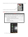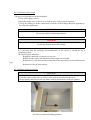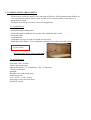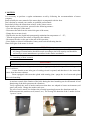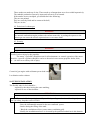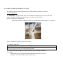
1
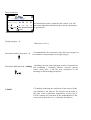
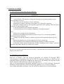
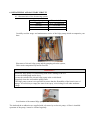
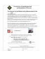
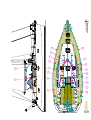
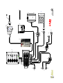
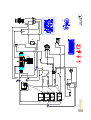
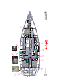
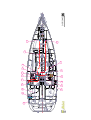
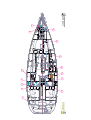
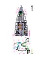
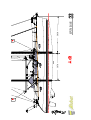
OWNER MANUAL ACCORDING TO EUROPEAN DIRECTIVE 94/25/CE AMENDED BY EUROPEAN DIRECTIVE 2003/44/CE OVNI 445 DESIGN CATEGORY A This document has 84 pages, numbered from 1 to 37, more than 47 pages of plans and diagrams. Your vendor Name _______________________________________________________________ Address _______________________________________________________________ _______________________________________________________________ Is the supplier of SAS CHANTIER ALUBAT and you can receive all the necessary assistance to solve the problems during launching and masting, as well as for technical control for commissioning of boat and maintenance of the boat. He will assist you for the administrative procedures of registration of your boat. Once you become the owner, you should have knowledge of the user manual delivered with your boat. The receipts are dated and signed at the bottom and are sent to your vendor. Guaranty conditions : see page 34 Cut along the pointed lines ----------------------------------------------------------------------------------------------------------------- Receipt of the user manual I the undersigned : Name ________________________________________________________________ Address ________________________________________________________________ ________________________________________________________________ Owner of the OVNI 495 n°_____________ Declared to have received the user manual of the OVNI 445 sail ship having: - The safety declaration of acceptability - The acceptability certificate at the tonnage type pleasure boat series. This pleasure boat is covered by guaranty conditions figuring at The page 34 of the present user manual. The guaranty starts at the __________( date of the day) Signature SOMMAIRE Introduction 1. Category of design of the boat 2. Technical characteristics 3. Electrical systems 4. Gas installation 5. Inner arrangement 6.Dewatering and sanitary circuit 7. Flooding 8. Protection against fire 9. Motor 10. Fuel installation 11. Steering system 12. Navigation 13. Protection against the lightning 14. Protection against the environment 15. Safety Shipping 16. Handling, transportation, grounding 17. Centerboard 18 Hull – alum maintenance 19 Guaranty and transfer of property 20. River and sea Chart 21 SNSM (National society for rescue in sea) Page 4 Page 5 Page 6 Page 8 Page11 Page13 Page18 Page20 Page21 Page25 Page26 Page27 Page28 Page29 Page29 Page30 Page30 Page31 Page32 Page34 Page36 Page37 PLANS 1 Presentation 2 Arrangement 3 Fittings 4 Sail 5 halyard and sheet circuit 6 220 v Circuit 7 Charge and power circuit 8 12 V Switch board 9 Centerboard 10 12v electrical installation 11 220V electrical implantation 12 Apparatus to be steered 13 Gas circuit 14 Ship evacuation 15 Soft water circuit 16 Dewatering circuit 17 Through Hull 18 Mechanical implantation 19 Gas oil circuit 20 Household water and black liquor 21 Holding tank 22 Raising plane 23 List of the attached documents Page39 Page41 Page44 Page46 Page48 Page50 Page52 Page54 Page56 Page58 Page60 Page62 Page64 Page66 Page68 Page70 Page72 Page74 Page76 Page78 Page80 Page82 Page84 INTRODUCTION Dear Sir, Dear Madam, Welcome to the family of owners of ALUBAT sailboat This Manuel has prepared for the owner to assist the usage of the sailboat with pleasure and safety. This manual contains the details about the boat, its equipments that are supplied and provided, its functional systems, and the information on their usage. Carefully read it and familiarize yourself with the boat before reaching the sea. Even if the boat is approved and is well equipped for the wind and sea conditions, corresponding to the A, B, C categories, such as tempest, abnormal wind condition, abnormal waves or squall, the navigation presents the danger for which only the trained and experienced person can navigate in a satisfactory manner. Ensure yourself about the wind condition and the sea condition corresponding to the category of the design of your boat, and make sure that you and your team are capable to operate the boat in these conditions. This manual is not on the safety of the navigation or about the marine knowledge. If this boat is your first boat or if you change the boat with the boat in which you are not familiar, for your comfort and for your safety, ensure yourself that you acquire an experience on its operation and its usage before taking the controls. Your dealers, your national federation of ship or power boating or your yacht club will be happy to inform you about the navigation schools and the qualified instructors of the region. This manual is not a detailed guide on the maintenance or on the repairing. In case of any difficulty call the constructor of the boat or its representative. Always use the services of experienced professional for maintenance and mounting of the accessories. The modification affecting the safety characteristics of the boat should be assessed, executed and documented by the competent persons. The boat constructors cannot be responsible for the modification that he has not approved. KEEP THIS MANUAL IN A SAFE PLACE AND GIVE IT TO THE NEW OWNER IF YOU SELL THE SHIP. WARNING: Our boats are regularly improved based on experience of our clients and the researches made by the shipyard, thus the specification given in the manual are not contractual and can be modified before and without obligation of any updation. This manual has for the aim to cover maximum number of information and thus the equipments or the paragraphs does not concern about the boat. In case of any doubt, refer to the inventor during your order. 1. CATEGORIE DE CONCEPTION DU NAVIRE Your OVNI 365 is in the design category of HIGH SEA (category A). In the normal usage conditions, your boat is designed to navigate in the waves of significant height of 7m and the high wind force of 10 or more, and to resist in the very severe conditions. This capacity to navigate depends also in the skill of the team, its physical capacity, maintenance of the boat and its fitting. Be careful before launching in the sea. The chantier Naval ALUBAT cannot guaranty perfect operation of the ship in the exceptional condition of sea (violent wind, hurricane, cyclone, tornado....) DESIGN CATEGORY Design category Navigation type Wind force (high force) Speed of the wind A B C D In high wave At high sea Near the sides In protected water Beyond 8 Up to 8 inclusive Up to 6 inclusive Up to 4 inclusive Until to 28 m/s Until to 21m/s Until to 17 m/s Until to 13 m/s Significant height of the wind to be considered Beyond 4 m Up to 4 m inclusive Up to 2 m inclusive Up to 0.5 m inclusive TAKE THE SEA, NO RISK Check the weather before starting to the sea. At the port : The harbor display the weather report and weather forecast for all the days. France meteorological at 08.36.68.08.08. Navifax - direct to 08.36.70.18.52. VHF : the CROSS emits much report per day, after the announcement in the channel 16. The chantier ALUBAT has chosen the institute for certification and standardization of water sports like the organization to verify the conformity of your boat at the European director office CE 94/25, in the frame of design category of the modules B and G. Identification The identification number of the hull is situated on the starboard side of the transom. It is constituted of series of letters and digits starting from FR-ALU 1.1 Degree of danger DANGER Indicates extreme intrinsic risk that results in large probability of death or irreparable wound if the appropriate precautions are not taken. WARNING Indicates that the risk can cause wound or death if appropriate precautions are not taken. ATTENTION Indicates practical safety measures or appropriate attention during dangerous practice which can result in the wound for persons or damage for the boat and its components. 2. TECHNICAL CHARACTERISTICS OF THE BOAT 2.1. General characteristics Model: Architecture: Design category No of notified organization CIN No Hull length: Waterline length: Maximum breadth : Draught Beam : Weight of the ballast : Slight displacement : Displacement in load GV Surface Genoa surface Staysail Water capacity without water heater (approx) Fuel Capacity (approx) Holding tank Engine battery (according to the version) Service battery Main means of propulsion Maximum admissible engine power OVNI 445 Marc Lombard A CE/0607 FR -ALU _____ 13.80 m 12.66 m 4.29 m 1.05/3.15 m 19.50 m 3 725 kg 10426 kg 13 182 kg 43.50 m² 53,90 m² 24,50 m² 540 L+(100 L) 500 L 75 L x2 90 Ah x 1 90Ah x 3 Voile 40,4 kw / 75 cv Note : The capacity of different tanks of fresh water and the fuel is not generally utilizable according to the trim or the loading of boat. For the fuel, it is recommended to save the 20% reserve. Plate constructor ZI Les Plesses - 85180 LE CHATEAU D' OLONNE OVNI 445 Catégorie de Design : A B C Max. Max. D The manufacturer plate is situated in the cockpit. You will find certain important information there whose explanations (kg) 2800 2800 2800 2800 are given below. 8 10 12 14 0607 Design category = A : Haute mer (voir 1.1) Maximum number of persons = 8 Maximum additional load = 3000 kg CE 0607 : recommended by the constructor when the boat navigates in sea condition corresponding to its design category. : including 8 persons with equipment, articles of personal use and victualling ( excluding different reservoir capacity (water, diesel fuel,...) and the load constituted by the mounting of different shipyard options. CE marking indicating the conformity of the boat to all the prescriptions of the director. The sequence of the digits is the code of the certification organisation. In hte case of ICNN ( Institute for certication of the standardisation of the water sports), Bruxelles (see : confirmity declaration) 3. ELECTRIC SYSTEMS 3.1. The electrical system safety and use guidelines WARNING Dos: - Verify the state of the batteries (charge and electrolyte level) and the charge system before launching in the sea. - Disconnect and set the batteries for the wintering. - Maintain the voltage of the battery more than 10.5 V during the wintering. - Bring the exchange bulbs for the navigation light and the inner lighting. Follow the power particularly for the navigation light. - Verify the operation of the navigation apparatus. - Verify the operation of the navigation light before the night navigation Don’t: - Work on low voltage electrical equipment. - Modify the installation and pertinent schemas, except if it is executed by qualified electrician in marine electricity. - Change or modify the capacity of rupture of the protection apparatus against the over intensity. - Replace the apparatus or electrical material by excess components The prescribed capacity without recalibrating the conductor and their protection - let the ship without supervision when the electrical installation is low voltage, except the automatic bilge pump and the fire or theft proof circuits. If a fuse or a circuit breaker does not cease to blow, a specialist has to be called to determine the origin of the short circuit. 3.2. Installation of new equipments From the 1st January 1996, the electrical equipments are subjected to European Rules « electromagnetic compatibility (Ref 89/336/CEE). It is thus not necessary to install the new equipments which responds to the standard and which carries CE markings. The apparatus should also be delivered with conformity certificate and usage notice. Only use electrical apparatus with double insulation in the case of 220V installation. During the installation of these apparatus, follow the mounting guidelines (wire sections, protection). To avoid the maintenance problems, carry the manual for modification of electrical schema. 3.3 Batteries The capacity of the batteries has been studied to meet the energy need of the accessories. To avoid the entire problem, it is necessary to ensure proper care and maintenance of the batteries. Parc of 3 batteries of servitude of 90 Ah below rear berth Bd. 1 battery of 90 Ah for engine starting Engine circuit breaker Servitude circuit breaker Windlass circuit breaker Windlass fuss Single pole safety circuit breaker GE circuit breaker in option Circuit breaker box on the front side of the rear carbine berth Bd ATTENTION - When you install new electrical apparatus, note that the overall consumption of the apparatus remains with respect to the capacity of your batteries. Always disconnect negative terminal of the battery before the positive terminal Never set to terminals of the battery in contact with each other by intermediate of conductor objects ( tools , etc... ) During the manipulation of the batteries, avoid all the electrolytic liquid leakage by maintaining them horizontally. Wear pants and clothes which avoids the risk of contact with electrolytic liquid in case of leakage. In case of projection of electrolyte, rinse thoroughly the part of the body that contacts with the body and consult the doctor. 3.4 Electrical windlass ATTENTION When you use the electrical windlass, it is imperative to operate your engine with slight acceleration. 3.5 Installation 220 Volts DANGER The 220V installation is protected by a circuit breaker and is provided with a differential block. The cabling of the 220V accessories of supplementary board should be carried out by the professional with appropriate recalibration of the general circuit breaker. During the maintenance out of sea water in closed position to have a ground protection via dock haul. Grounding circuit breaker of sailboat besides the water Location of general 220 v int. Circuit breaker in the rear cockpit Bd Attention ! When the ship is at dock put the circuit breaker in open position. DANGER Your boat is delivered with a boat/platform supply cable and male plug near the terminal wharf. The cable is provided for outside usage. Its section is adapted according to the length and power of the main circuit breaker ( see electrical diagram). The plug is adapted to the female plug of the wharf ( you inform the profession if necessary). It is very near to the type IP 67 / IEC529 - Cut the supply to wharf at the level of the sectioning device installed before connecting or disconnecting boat supply cable/wharf. - Connect the boat supply cable/wharf on the boat before connecting it on the wharf terminal - Disconnect the boat supply cable/ wharf on the wharf terminal before disconnecting it from the boat - Close the protection of the supply inlet at the wharf 220 v Table at the card board with voltage indicator 4. GAS INSTALLATION 4.1Guidelines for usage Carefully read the usage notice of the stove and the pressure regulator. Ensure the conformity of the gas cylinder and pressure regulator to the specification of the stove (flow, pressure, gas type). Ensure the conformity of the gas cylinder to the current rules in the country of usage. - The apparatus burning the fuel consumes the oxygen of the cabin and rejects the combustion products in the ship. Ventilation is necessary when the apparatus functions. Open the windows of the roof when you cook. Do not close the rapid access to the gas installation elements ( cylinder cover, shut-off cork). The gas cylinder should always be interposed in its housing. Stove/Furnace Gas supply valve under the stove - Do not let the ship without supervision when the gas apparatus functions. Close the assembly of circuit valves when the boat is not occupied (shut-off valve, pressure valve tap), even when the bottle is empty. Do not smoke when you descend inside the boat when the boat is closed, ensures that there is absence of gas odor. If you smell a gas odor, close the valves of the circuit and valves of stove, ventilate the boat, detect the leakage before setting the installation in operation. WARNING The valves of the circuit should be immediately closed in case of emergency. 4.2 Verification of the circuit - The gas circuit should be tested periodically: ° Close all the galley valves. ° Open the supply valve of the stove as well as valve of the pressure regulator. ° Verify the sealing of all the connections by means of the leakage detection apparatus or by soap water application. ATTENTION! Do not use solution containing ammonia. DANGER! Do not use flame to detect the leakage. pipe, - It is necessary that the repairing and modification of the circuit is carried out by a competent person The flexible pipes should be: Regularly controlled, at least once in an year, Replaced if the expiry date mentioned on the pipe has exceeded, Replaced five years after the fabrication date of the pipe which can be marked on the Replaced in case of deterioration 4.3. Changing of the gas cylinder DANGER! - Close the valves of the stove as well as valves that are found before the stove. - Do not smoke, and Don not use any flame assuring replacement of the gas cylinder. Gas Deck in starboard bathing platform 5. 3 CABINES INNER ARRANGMENT All the Joinery works are made by rose oak under solid form. All the partitions and dividers are screwed and glued with the shell or deck. All the wood, are protected by several layers of polyurethane varnish. The floors are made up of counter veneer roving light nets. 5.1. Companionway Smoked Plexiglas sliding hatch Smoked Plexiglas washboard in two parts with ventilation and s/s lock Solid teak frame 2 teak handrails Companionway steps in solid wood with non-slip strips Immovable lower panel (+ Fire extinguisher opening): Front side access to the motor. In case of fire Opening for the nozzle of the extinguisher 5.2. Navigation post Chart table 780 x 550 mm Library and storage space Main switch panel 12 v: 20 functions – 220 v: 5 functions 1 Flexible chart table Spotlight Navigator seat with storage space Chart storage unit 1 12 v socket + 1 220 v socket Fuel gauge, fresh water flow meter Electronic console 5.3. Saloon Portside Lateral settee and settee in vis-à-vis on centerboard well Cushions and backrests made up of fabric Small side locker behind settee with storage space Laminated teak striped floors Ventilation and lighting by 2 portholes on fixed hull, and 2 deck hatches with curtains 4 spot lights White headlining on roofs and oak wood on edges Storage space under side settee and central bench Saloon table 5.4. Galley Functional Arrangement Large worktop and numerous storages 2 s/s sinks Pressurized hot and cold water mixing tap Gimbaled s/s two burner stove with oven, s/s hand rail 160 L Refrigerator Two self dressers with doors Ventilation and lighting through 1 fixed hull porthole and 1 hatch on coach roof with curtains Sea water foot pump Trimmed work top Ventilated storage space for cooking utensils Laminated teak striped floors 1 220v socket, 1 spotlight 5.5. Front Carbine Standard lateral double bed (central in option) with high density foam mattress. It is easily lift able. Storage space under head of berth Hanging locker unit in external gangway 1 deck hatch with curtain (safety escape in case of fire) Thick cabin door 2 spot lights Laminated teak striped floors 1 adjustable reading lamp Small side locker with storage space 5.6. Front shower toilet compartment ( std ) Access door with lock Laminate bulkheads WC manual 1 cupboard with shelves 1 mirror Washbasin with pressurized hot and cold water tap/shower 1 electric shower discharge pump, teak grating Light and ventilation through deck hatch with curtain White laminate unit containing a hanging locker 1 spot light, 1 220v socket 5.7. Starboard AFT carbine Standard lateral double bed with high density foam mattress. It is easily liftable. 1 large ventilated hanging locker Storage space under the berth Rudderstock along the edge Ventilation and light through coaming portholes, and the cockpit (with curtain optionally) Door to saloon with lock Inspection hatch to motor and technical zone (GE and water maker optionally) 1spotlight and 2 directionless reading lights Reservoir holding tank of 75 L (behind the hanging locker) 5.8. Portside AFT carbine double berth with high density foam mattress. It is easily liftable. 1 large ventilated hanging locker storage space under foot of berth Rudderstock along the edge Ventilation and light through coaming portholes, and the cockpit (with curtain) Door to saloon with lock Inspection hatch to motor 1spotlight and 2 directionless reading lights Motor and servitude batteries parc storage 12V electric circuit breaker under the bed (access in front of berth) 5.9. AFT Toilet-shower compartment ( std ) Door to saloon with lock Laminate bulkhead WC manual 1 cupboard with shelves 1 mirror Washbasin with pressurized hot and cold water tap/shower 1 electric shower discharge pump, teak grating Light and ventilation through deck hatch with curtains White laminate unit comprising a hanging lock 1 spotlight, 1 220v socket 5.10. Engine compartment 55 CV insulated two pole Diesel engine Soundproof and ventilated by 1 input / 1 output engine 4 batteries 12v- 90 Ah ( 3 servitudes and 1 motor ) Battery charger and load distributor 22 L water heater; 220v power supply and via engine heat exchanger 1 electric bilge pump Entire engine instrument panel on column; Single lever gas control Three blade propeller on shaft with anode Ø 30 mm Load distributor Anti-siphon Sea water filter First compartment accessible behind companion ladder Second soundproof compartment GE sea water head gate (optional) Engine sea water head gate Placement under rear carbine floor Bd 6. DEWATERING AND SANITARY CIRCUIT 6.1. Characteristics of the dewatering system Type of pump Manual 12v well Theoretical flow 39 L / 60 turns/min 16 l / mn Carefully read the usage and maintenance notice of the bilge pump which accompanies your boat. Placement of electric bilge pump and the pumping selection system, Under main companionway lateral floor Bd WARNING ! -Ensure the bilge pump is in functioning state before starting to the sea. - Locate the hand pump and its lever, - Locate the switch of the electric bilge pump at the switch board - Regularly clean the well and the pump filters - The bilge pump system is not provided to ensure that the floatability of the boat in case of damage. It is necessary to empty the water from spray, valve leakage or all other moderate leakage. Localization of the manual bilge pump on Bd in the cockpit The sink and the washbasins are supplied with soft water by an electric pump. A filter is installed upstream of the pump, it must be cleaned regularly. Electric bilge pump of shower Pressurized water unit Filter Flow meter Water tank selection valve Bd or Td Localization of pressurized water supply unit under lateral floor of main companionway Td Do not turn the pump if the tank is empty. Fill it fully. It is possible to sterilize the reservoir with the help of clonazone pellet ( that is in sales in pharmacy).Each year, please demount the inspection panel in order to clean it by replacing the water added with bactericide detergent, let this product act some hours then make 2 to 3 rinsing. In winter, fill the tank fully to avoid the proliferation of algae or bacteria, or empty the reservoirs if there is a risk of frost, never use the antifreeze agent. The hot water is produced by water heater connected on the cooling circuit of the engine and electric plug of wharf. After emptying water heater, make sure that the heater is immersed before setting in low voltage. 6.3. Valves The valves are of type ¼ of turn: - OPEN position : lever in the direction of the body of the valve, - CLOSED position: level perpendicular to the body of the valve. Vanne ouverte Vanne fermée - CLOSED position: level perpendicular to the body of the valve ATTENTION ! - Never touch the locking of the valves on the hull. In case of leakage, consult the professional. - During bad weather or while quitting your boat, close all the valves of the sanitary circuits. - Maintain the valves closed when they are not used. - During the wintering, clean and rinse the hull and the valve. Inspect the accessories . In case of serious repair, consult the retailer. 6.4. Operation of marine water closet - Open the inlet sea water valve. - Open the exhaust valve of the bowl. - Set the lever on a « FLUSH » position (flushing). - Operate the pump. - To empty the bowl and to avoid all movement of water to the deposit, position the lever on the « DRY BOWL » (Drying of the bowl). - Operate the pump till the drying of the bowl. - Repeat this flushing/drying operation of the bowl as many times necessary to ensure complete evacuation of the pipes. When the water closet are not used, set the level in « DRY BOWL » position, or for certain models on the « KEY » position - Close the valve after usage, the water closet is situated below the waterline Regularly change the joints of the water closet filter 7. FLOODING Risk of flooding of boat: - Verify the closing of scuttles and the deck panels or other openings permitting the flooding before starting the navigation . - During the navigation under sails, close all the valves, except the engine water outlet. - Verify periodically: - The sealing of through hull, valves and hose. - The good flow of discharge from cockpit. - The sealing of stern tube gland. WARNING ! The deck lid of cockpit should be closed and locked before starting the navigation. This is more important for the decks having high risk of flooding 8. PROTECTION AGAINST THE FIRE 8.1. Installation - The extinguishers are subjected to national laws, due to that your boat is delivered without the extinguisher. - We invite you to equip your boat with extinguisher, according to the ISO 9094-1 standard, at following conditions : a) Minimum capacity of extinguisher : 5A/34B, b) Combined minimum capacity of extinguisher : 10A/68B, c) 1 extinguisher at least for: - 1 m for boat <10 m or 2 m for boat >10m of cockpit - 2 m of the discharge orifice to clean the motor, d) 1 extinguisher at least for 2 m of stove, e) 1 extinguisher at least for 5 m of berth. f) The carbon dioxide extinguishers can be placed only in the living room where the inflammable liquids are present (Ex. :Galley) or the low voltage electric equipments are present. There should be only one CO2 extinguisher per risk zone and its maximum capacity should not be more than 2 Kg. Only the compatible replacement parts should be used for the fire-proof system. The parts should have the same indications and are equivalent technically. WARNING If the CO2 extinguisher is installed, the following information should be displayed near its location : « This extinguisher contains the CO2 – Only use this to put-off the fire coming from the electric apparatus or for the galley fire. To avoid the asphyxia after discharge, leave the zone immediately. Ventilate the zone before entering. » After the extinction of fire, do not immediately open the engine compartment to avoid the exit of toxic fumes and projection of incandescent products (oil, water). 8.2. Safety Guidelines ATTENTION It is the responsibility of owner/Skipper: - To verify the fire fighting equipments according to the instructions of manufacturer and the rules of your country. - To replace the fire fighting material if it is expired or off-loaded, by the extinguisher apparatus of equal or higher capacity. - To indicate to the team members: • The location and the operation of the fire fighting material • The location of the spill port of the engine compartment (situated on the front side of the main descent ladder). - To assure that the fire fighting material is easily accessible when the boat is occupied. Don’t: - Close the passage to the emergency exit (deck panels). - Close the safety control (gas valves, fuel valves, and electric switches). - Close the storage containing the extinguisher. - Leave the unoccupied boat with the ignited stove or heater. - Use the gas lamp in the boat. - Fill the fuel tank or change the gas cylinder when the motor, the stove or the heater functioning. - Smoke during manipulation of the fuel or gas. - Hook the curtains hanging freely close to the stove or other open flame apparatus. - Store the combustible products in the engine compartment. - Protect always the proper holds and verify whether there is no presence of fuel or gas vapor . CHECK LIST FOR STARTING MOTOR : Open the engine suction valve Open the fuel valve Verify the level of engine oil Verify the level of cooling liquid Verify the level of batteries Gas control lever at dead point, clutch at dead point Make the contact Start Control the water outlet Extinctions of alarms and top marks Heat the engine slowly for 5 to 6 minutes Verify the good sealing of all the combustible, exhaust and lubricant cooling circuits In case of doubt or problem, consult the proprietor manual, the technical guidelines, the plans or your retailer. TO STOP MOTOR: Slow down the motor for 5 minutes Tie on the lazyjack handle or Push Stop button Disconnect the contact Close the different valves. In case of doubt or problem, consult the user manual, the technical guidelines, the plans or your retailer. FOR FILLING TANK : Extinguisher at proximity Off motor Disconnect electric equipments Close Deck panels and Scuttle Don’t fill the tank completely for permitting the expansion of the fuel In case of doubt or problem, consult the proprietor manual, the technical guidelines, the plans or your retailer. BEFORE THE STARTING FROM PORT Meteorological condition Refueling Dress for the navigation Documents and equipments necessary at board and during the journey Safety equipments (life jacket, harness, extinguisher, distress spindle, emergency tiller) Safety guidelines given to the team with the mention of location of equipments Bilge pumps in running state Navigation light in good state Filled fuel tank Filled water tank Verify the good sealing of all the circuits Verify the level of cooling liquid Verification of good functioning of rudders Proper gas-oil filter in good state Level of engine oil Level of batteries Rigging in good condition (tension of shrouds) Fittings in good condition (pulleys, winches, ropes, furling, handles, camming device) Sail in good condition (seams, bolt rope, traveler) Close the portholes and hull panels In case of doubt or problem, consult the user manual, the technical guidelines, the plans or your retailer. AT RETURN : Boat correctly moored and protected Dried and stored sails Dried and stored safety equipments Rinsing of boat with fresh water Space the halyards so that the halyards do not flutter Coil the different fag ends No leakage of fuel circuits No leakage of sanitary and dewatering Closing the valves Open the fridge Close the electric circuit In case of doubt or problem, consult the user manual, the technical guidelines, the plans or your retailer. 9 MOTEUR It is necessary to perform a regular maintenance work by following the recommendation of motor company. Read carefully the user manual of the motor that is accompanied with the boat. Don’t hesitate to consult your retailer or qualified professionals. Particularly follow the instructions relative to the winter season. In the absence of the precisions, proceed in the following manner : - Close the inlet gate of the motor, - Disconnect the tube from the water inlet gate of the motor, - Empty the sea water circuit, - Dip the tube into the liquid tank permanently maintained at temperature of –25°, - Turn the engine until to the release of liquid by the exhaust, - Reconnect the tube on the gate at the end of the operation, - Put a display at electric board and at battery main switch indicating that the Water Inlet gate of the motor is closed . - ATTENTION Do not navigate under the sail and motor if the angle of heel is greater than 10° All change of motorization should be made according to the boat capacity and should be realized by a motor manufacturer specialized in the marine mechanics. 9.1. Launching of boat/ controls ATTENTION After the first launching and tensioning of rigging, verify the lineage of line shifting or the skirt of sail drive. Assure that the water inlet gate of cooling circuit is opened, and that there is the water that comes from the motor exhaust. Boats equipped with stern tube gland with rotating joint : purge the air of stern tube gland after each launching. A succinct control of the fixation of the helix during the later launching can be effectuated. A bad functioning of the helix generates the vibrations Verify regularly the state of anodes and assure that these are adapted to better environment (soft water, salt water). Change the anodes each year. The role of active anode is to balance the potential appearing between the aluminum and. the different materials (stainless steel, bronze, etc.). The average life duration of the 3 anodes is from 1 year to 2 years. These anodes are made up of zinc, Those made up of magnesium are to be avoided imperatively. The cathodic production system by impressed current is to be banned. If the anodes are not corrupted, you should check the following: They are not painted, They are correctly fixed and in contact with shell, They are in zinc 9.2. Emission of exhaust gas DANGER ! The internal combustion engine produces the carbon monoxide. A prolonged exposure to the exhaust gas can cause the serious repercussion or even cause death. 9.3. Security DANGER ! The motor should not be in run when the swimmers swim close to the boat in order to avoid all risk of serious injury by the propeller. The motor, if possible, should not run for all maintenance or control operation of the motor. otherwise, a specific vigilance should be carrier to the units in movement (propeller shafts, belts, etc…) in order to avoid any risk of injury. Control of gas engine with red button put at dead center Localization on bar column 10. FUEL INSTALLATION The flexible tube for fuel should be : - replaced by the tubes having the same marking, - replaced in case of deterioration. ATTENTION ! The nominal fuel capacity is not fully useable depending on the trim and loading of your boat. For safety, keep the reserve of 20%. Never: - Store the inflammable material in the non-ventilated spaces. - Smoke during the filling of the tank. - Block the ventilation orifices (vents, motor ventilation grid). - Modify the installation unless it is executed by the qualified technician in this domain. 11. DOUBLE RUDDER STEERING SYSTEM The steering system is a main element for the safety and the comfort of your boat. 11.1 Steering wheel The OVNI 445 is equipped with a help with mechanical transmission system by shaft and cardon. The final connection with the locks is made by the double link.. Periodic control to be effectuated: - Control the clearance of different elements (main rudder blade/bearings, tie rod axles ) In case of doubt or problem, consult your retailer. 11.2. Backup hand tiller ATTENTION - The OVNI 445 is equipped of a backup hand tiller that should remain easily accessible, we advised you to store it in a near well deck of plug hole. - It is only designed to navigate at reduced speed in case of damage of the bar For the user: - Unscrew the cap of the plug hole under the base duckboard of cockpit , - Install the bar on the header of main rudder blade. 12. NAVIGATION WARNING - In all the situations, adapt the speed of your boat to environment conditions and conserve a margin of safety. Take special care: To the state of sea, to currents, to the wind force. To traffic. To maneuver of port. To passages in the mooring zones. - Observe the priority rules such as those are defined by the rules of the road and imposed by the COLREG - Makes sure always you have a sufficient distance to stop or maneuver if necessary avoid the accident - Obey the speed limitation zones . - For the curtsey and safety of the other boats, make sure that you don’t produce more waves near other small boats WARNING - You must equip your boat with life lines. The anchoring points are provided on the deck. At the level of anchoring cleats or pits of washboard rail.. - The stability of your boat has been studied by taking into account the yard catalogue options. All change in the disposition of aboard weights (for example: the addition of a radar, the changing of a motor etc…) can affect the stability, trim and the performances of your boat. - The towage of a boat drives an overload, having unfavorable incidence on the stability of your boat. - Never : Lift more weights with the help of a boom. . 13. PROTECTION AGAINST THE LIGHTNING Your boat is protected against the lightning. It is however necessary for your safety follow certain precautions. 13.1. Maintenance If the boat was hit by the lightning: - The safety devices should be checked to detect the damages and check the integrity of the device. - The compasses, electric and electronic devices should be examined in order to determine whether the damages or the changing of compass calibration are happened. 13.2. Protection of persons during storm WARNING During a storm, It is preferable to follow the following instructions : - The people must be held as much as possible inside the boat. - The people should not be in water or let hang their arms and their legs inside the water. - While ensuring adequate control of ship and the navigation, the people should not touch any part connected to the lightning protection installation, especially these parts should not be connected to the installation. - It is desirable that the people avoid the contact with the metal parts of rigging, the spars, the fitting parts and the cables. 14. ENVIRONMENT PROTECTION AND SAFETY We will inform you the local rules about the environment protection, and to follow the international rules against the pollution in marine medium (MARPOL) as well a good code of conducts. ATTENTION ! - Most maintenance parts, engine oils, and hydrocarbon fuels are not neutral for the environment, but these things should be unloaded only in the regulated places (check yourself within the harbor). - Some products may also present the risk for your safety and for others that is why it is important to read and follow the use advice. - The used substances should be tagged and stored in the ventilated and appropriated place of boat. 15. SAFETY SHIPPING The compulsory safety shipping is not harmonized within the European community. It should inform you about the current national requirements for the boats marked with CE. In France, the pleasure boats having the CE mark should posses on board the provided safety and shipping material for the navigation category retained by the boater in the following limits: Category of design A B C D Category of possible navigation 1.2.3.4.5.6 2.3.4.5.6 4.5.6 6 Your boar should be equipped with survival raft, read carefully its user manual . The team should be familiarizing with the usage of all the safety material (harness, signal rocket, survival raft, etc…), The boat schools and the clubs organizing regularly the training sessions . 16. HANDLING, TRANSPORT, GROUNDING During the cranage, Make sure that the slings are correctly positioned and these are not supporting on the propeller, propeller shaft or a brittle probe. The Frame derricks will be wide enough or equipped with spacers so as not exert the excessive transversal force on the moldings. Avoid that the slings carrying on the steel cable. During the transport or the grounding, it is convenient that the keel is well supported by its sole in small draught position and supports mainly the weights of boat. The cradle duck foots should be positioned at level of structural elements and only exert the pressure necessary to good equilibrium of boat. Enjoy water ridings to inspect the propeller, the rudder blade, the through-hull and the probes 17. CENTERBOARD 17.1 Maneuver of the Centerboard On the OVNI 445 , the maneuver of the Centerboard is effectuated by hydraulic jack via the pump situated in the cockpit . Your yacht is equipped of a reliable hydraulic material; Some precautions are necessary for usage and maintenance. ATTENTION At the approach of shallow waters free your centre-board. View of centerboard well under lateral settee of saloon. Use always the same hydraulic oil ( glycol or glycol water ), observe the level and the property of this oil. Have a complete overhaul of system of boat during the winter season. Operate the Centerboard occasionally to prevent the sticking of joints and the formation of deposits on the ram-rod. PRECAUTION In navigation, always bring the inverter in neutral position, in order to get the advantage of safety fuse of limiter. Vessel with hydraulic liquid Limiter : In case of tailgating, re-change fuses are situated under the black cap of fuse door Maneuvering arm Inverter hand lever Localization of the pump inside the rear cockpit Td 17.2 Utilization of the pump Companion way of the Centerboard: Direct the inverter in stop position to the bottom ( lower ), the centerboard should brought down, Pump out until to hardening of operating arm in order to lock in pressure, Bring the inverter to the horizontal position ( neutral ) Raise the centerboard Direct the inverter in stop to the top (Up), Pump out until the hardening of operating arm Approximately 35 turns Bring the inverter to the horizontal position ( neutral ) It is advisable, at each winter, clean the wells of centerboard and its Fractal pads, ( If those are worn, it should be replaced) ATTENTION Put the centerboard in lifted position when you leave the yacht During the wintering, or for all prolonged non-utilization position, maintain the centerboard and rudder in top position to : Avoid the displacement of algae and seashell on the centerboard Protect the ram rod of rudder 18. HULL – MAINTENANCE OF THE ALU. 18.1 Prevention The protection of the aluminum exposed to the marine medium is not indispensable contrary to lot of other metallic materials. However, two types of protection are imposed for the modern pleasure boat: Protection of all the immersed surfaces against the animal and vegetable deposits, Cathodic protection of the aluminum structure in reason of the presence of materiel potentially different. The painting of non immersed surfaces (dead works) is only for the purpose of aesthetics orientation. 18.2 Painting maintenance (dead works) An integral riding sail made up of aluminum is particularly easy to maintenance, to condition of take some precautions as for the choice of products and to their application in order to avoid all chemical reaction among the products. Use the same brand and quality paints, Follow the manufacturer instructions, Don’t hesitate to request the advice from the manufacturer or your ALUBAT adviser. It is possible to effectuate your self the partial distributions of paints and connections by respecting the following precautions : Choose a room with the shelter for protection against the dust and wind, temperature greater than l5°C, humidity comprised between 40 and 70 %, Store the paint buckets in the same room for 24 hours in advance, Do not apply the paint on the surfaces having subjected to sudden variation of temperature (following to sand papering for example). ATTENTION At the occasion of Shock (crank of winch falls on the deck, etc… ), the superficial layers of the paint can be damaged, you must, as soon as possible, provide a painting touch such that the moisture cannot penetrate inside the intermediate layers. Delaying this operation can highly damage (blisters, unsticking ) to the paint of your boat. 18.3 Repairing Damaged surfaces : If the aluminum has been exposing to air: Degreasing Rinsing with the pure water Drying Rubbing with the abrasive (180-220) by putting the largely bare metal around the damaged area First Epoxy layer (120 microns humid) Epoxy coated putty 833 for leveling 1 Surfacer (120-140 microns humid) 2 Varnish Coat (2 x 120 microns humid) If the intermediate layers have not been reached Degreasing Rinsing with the pure water Drying Abrasive Sand papering with the water (250-300) without touch the intermediate layers 1 Primer (120-140 microns humidity) 2 Varnish coat (2 x 120 microns humidity) 18.4 Maintenance of none painted edges In order to delay the development of the alumina on this not painted parts, Alubat has coated these parts with special wax. The action of those has not exceeded for some months. And, in any case, the development of alumina, quite normal on the aluminum, cannot be detrimental at the durability of hull of your. 18.5 Five year maintenance of under works The ALUBAT shipyard insists on the necessity of put the under works to the boat for every five years. Sandblast Degreasing Rinsing with pure water Drying 1st epoxy layer ( 120 microns humidity ) 2nd epoxy layer ( 260 microns humidity ) Anti-fouling fixture ( 130 microns humidity ) 2 layers of anti-fouling ( 2 x 110 microns humidity ) 19. GURANTEE AND TRANSFER OF PROPERTY We guarantee during the legal period for any defect that make our products unfit for navigation. All modifications of products, particularly by adding the parts other than the original parts results the forfeiture of the guarantee. The guarantee permits the purchaser to obtain the repair and replacement of known defective parts, when the user has proceeded normally and properly to the required maintenance. Our guarantee does not cover the handling and transport costs, or any other damage, particularly related to the detention of the boat. Statutory warranty The construction site should give the statutory warranty defined in articles 7 and 8 of the law number 6765 DU 3/01/67 concerning the status of boats, and as follows: Article 7 : The manufacturer guarantees defects of the boat despite the unconditional receipt by the Customer. Article 8 : The action against the manufacturer is prescribed by a year. This time delay starts soon after the discovery of the defect. Contractual Warranty Without affect the statutory warranty, the owner, who is the owner of the company ………………..Or………………...a personal title holder of the Guarantee for an year, starting from the defined day of the receipt of boat, versus, among others, all material or manufacturing failure. The guarantee is applicable to the whole boat, materials and materials installed in the boat by the shipyard, its suppliers and its sub-contractors who have been appointed by the ship yard. The warranty is applicable to the parts and the labor It is limited to the overhauling or to replacement of defective parts or materials at the usage, without that the manufacturer has to cover the costs and the consequence of failure. The guarantee is withdrawn and the manufacturer disengages from his responsibility when : The material has been transformed, modified, or repaired out of shipyard without prior authorization of the manufacturer. A- If the usage does not correspond to its technical characteristics, B- The damages are due to the perils of sea, negligence, improper maintenance. The buyer can have the guarantee only if he notifies the manufacture by letter with acknowledgement of receipt, within a month from the finding of defects. Litigation The manufacturer and the buyer are committed to find before any legal action an amicable solution by the intermediate of a person chosen by common agreement between the two parties. The intermediate person should give his opinion within a month Attribution of jurisdiction Any dispute is raised due to interpretation or the application of present contract will be the exclusive jurisdiction of the courts in the manufacturer head quarters, acting in French law, even in case of guarantee or of advocates . PROPERTY TRANSFER CERTIFICATE TRANSFER OF OWNERSHIP Le bateau modèle / Modèle boat :.......................................................................................................................... N° de coque / Hull N°:.......................................................................................................................................... De / From M / Mr:............................................................Adresse / Address:...................................................... ............................................................................................................................................................................... C-P / ZIP CODE :......................................Ville / City :................................................Tél :................................ Date d’achat / Date of Purchase :........................................................................................................................... A ETE VENDU A / BEING SOLD TO : M / Mr : …………………………. Adresse / Address : ………………………………………………………. ............................................................................................................................................................................... C-P / ZIP CODE :............................................Ville / City :.......................................Tél :................................... Date d’achat / Date of Purchase : .......................................................................................................................... Fait à ...........................................................................le ...................................................................................... Le vendeur / Seller L’acheteur / Buyer ALUBAT le : ............................................................. Exemplaire à retourner dans les 15 jours suivant la transaction a Return the copy within 15 days after the transaction to 20. CHART FOR THE SEA Chart for the sea And the rivers The water is a living medium, fragile. Hence this is a precious resource. To protect this medium, I respect the sea and rivers, I do not reach the protected sites, I limit my fishing to species and permitted sizes, I observe the animals without touching or disturbing them. Before the berth, I know about the nature of sea bottom to avoid its degradation. Preferably, I use the mooring buoy. I place my household wastes in the containers and my liquid and solid toxic wastes in the port. I use port sanitary installations. I empty my black water tray in the pumping station. I use the detergent products the most environmentally friendly I make sure that any maintenance operation (boat, material, equipment) is carried out with the care of the environment. I handle with care all liquids that could pollute during their transfer. To services of yachtsman and professionals of the sea To services of yachtman and professionals of the sea The sea salvers ensure... All the sailors know that they should not take lightly with the large blue ... Despite the considerable progress made in safety material by the Boat manufacturers, a peril of sea is always possible and you could have a necessary things for «sea salvers». At any time of day and night, 7 days on 7, 3 500 volunteer are ready to sail in half an hour to go and bring relief materials to those who are in trouble ... and those sometimes risking their own lives! Thanks to well interconnected network of its 255 stations in France and in the D.O.M. who « the Sea salvers » are carrying out close to 50% of rescue services in France today. In sea, you might need them, at ground they will fulfill your need ... The rescue of human life is free service but the operating means are very costly. The sea salvers, who are recruited more and more among the boaters, who needs your help to maintain, modernize and replace their nautical means (1 boat costs to 4,2 MF !). Hence Come to support them or joint with these sailors, men and women, selfless, discreet and efficient: have contact with the responsible person of the station more close to the port attached with your boat or with our head office in Paris. ENTER MARINS… - Before reaching the sea, inform your intentions to the family Yourself enquire the local conditions (meteorological, current, etc) - Have reliable VHF radio means and check them - Wear a lifejacket to children A HUMAN LIFE IS PRICELESS …, A LIFE BOAT IS THERE FOR YOU ! I support the SNSM and I join it ! I enclose a cheque: D130 FF min (20 €) - D300 FF (45 €) (donor) - D2500 FF (380 €) (benefactor) A receipt for tax deductibility can be sent to my address with the membership card and sticker NAME:…………………………………………………FIRST NAME:……………………………… ADDRESS………………………………………………………………………………………… Telephone::……………………………………………email::……………………………… PLANS 1 Presentation 2 Development 3 Fittings 4 Boat 5 Halyard Circuit and sheets 6 220 v Circuit 7 Power and charge circuit 8 12 v Switchboard 9 Centerboard 10 12 v Electric installation 11 220 v Electric installation 12 Steering Gear 13 Gas flow circuit 14 Evacuation of boat 15 Freshwater circuit 16 Dewatering circuit 17 Through-Hull 18 Mechanical installation 19 Diesel Fuel flow circuit 20 Household waste water and Black water 21 Holding tank 22 Lifting plan 23 List of Annexed documents Page39 Page41 Page44 Page46 Page48 Page50 Page52 Page54 Page56 Page58 Page60 Page62 Page64 Page66 Page68 Page70 Page72 Page74 Page76 Page78 Page80 Page82 Page84 OVNI 445 OVNI 445 PRESENTATION Plan de présentation Lg de coque 13,80 m Lg flottaison 12,66 m Bau maximum 4,29 m Tirant d' eau ( dérive basse ) 3,15 m Tirant d' eau ( dérive haute ) Tirant d' air Déplacement 1,05 m 19,50 m 10426 kg Poids du lest 3725 kg Homologation C.E. - Catégorie A Index 1 : Plan de présentation Index 2 : Plan d'aménagement Index 3 : Plan d'accastillage Index 4 : Plan de voilure Index 5 : Plan de manœuvre Index 6 : Circuit 220 V Index 7 : Circuit de charge Index 8 : Tableau électrique 12 V Index 9 : Plan de dérive Index 10 : Implantation 12 V Index 11 : Implantation 220 V Index 12 : Système de gouvernail Index 13 : Circuit gaz Index 14 : Evacuation et extincteurs Index 15 : Circuit d'eau douce Index 16 : Circuit d'assèchement Index 17 : Evacuation et vannes Index 18 : Implantation moteur Index 19 : Circuit gasoil Index 20 : Eaux grises et noires Index 21 : Holding tank Index 22 : Plan de grutage PRESENTATION Plan of presentation Length of hull Waterline length m maximum Breadth 13.80 m 12.66 4,29 m Draught ( Lower Centerboard ) 3.15 m Draught ( Upper Centerboard ) 1.05 m Air draught 19.50 m Displacement 10426 kg Ballast weight 3725 kg Length of hull 14,95 m Qualification C.E. – Category A Index 1 : presentation plan Index2 : Development plan Index3 : Fitting plan Index 4 : Boat plan Index5 : Operation plan Index6 : 220V circuit Index7 : Charging circuit Index8 : 12V electric panel Index 9 : Centerboard plan Index 10 : 12V electric installation Index 11 : 220V electric installation Index 12 : Steering gear Index 13 : Gas flow circuit Index 14 : evacuation and extinguisher Index 15 : pure water circuit Index 16 : Dewatering circuit Index 17 : Evacuation and valves Index 18 : Motor installation Index 19 : Diesel fuel flow circuit Index 20 : Household wastewater and block water Index 21 : holding tank Index 22 : Cranage plan V O LV O D 2- 55 OVNI 445 Fig A V O LV O D 2- 55 OVNI 445 Fig B OVNI 445 AMENAGEMENT ACCOMMODATIONS Version 3 Cab. (Standard) Fib A 2 Cabines double arrière 1 Carbine double à bâbord av. Carbine 2 lits superposés à tribord av. 1 1 Cabinet toilette à tribord arrière 1 Cabinet toilette centrale avant 1 Cuisine équipé Version 3 Cab. (Standard) Fig A 2 1 1 1 1 1 Version 3 Cab. (Option) Fib B 2 1 1 1 1 Cabines double arrière Carbine double à bâbord av. Cabinet toilette à tribord arrière Cabinet toilette centrale avant Cuisine équipé Rear double carbine Front portside double carbine Front Starboard superposed 2 birth carbine Toilet cabinet with rear starboard Front central toilet carbine Equipped kitchen Version 3 Cab. (Option) Fib B 2 Rear double carbine Front portside double carbine Rear Starboard toilet carbine Front central toilet carbine Equipped kitchen 26 05 C 05 04 29 03 30 26 25 04 20 31 15 06 07 13 14 03 15 09 10 21 19 11 03 12 16 22 03 16 G F C F G C 17 03 11 12 16 03 29 03 19 18 16 21 09 06 15 C D 15 13 14 07 10 08 31 20 24 29 03 E 03 03 04 03 C 06 03 05 28 B 23 01 B A 01 OVNI 445 G 02 C 27 OVNI 445 ACCASTILLAGE Rep . 1 2 3 4 5 6 7 8 9 Désignation Taquet d'amarrage avant Guindeau électrique Chandelier Inox Panneau ouvrant 60 x 60 Cadène Panneau ouvrant 50 x 30 (* à l’avant) Boite à réas plat pont Siége barreur Roller de Génois Chandelier Inox de coupée FITTINGS Ref 1 2 3 4 5 6 7 8 9 10 11 12 Bloqueurs Hublot latéral fixe 10 11 12 13 Winch alu self tailing de Spi 13 14 15 16 17 18 Winch alu self tailing de Génois Taquet d'amarrage Main courante Panneaux coulissant Compas 14 15 16 17 18 19 20 21 22 23 24 25 26 27 28 29 30 Winch alu self tailing de manœuvre Nable de remplissage d'eau Nable de remplissage fuel Chariot écoute G.V Balcon avant Balcon arrière Coffre cockpit Echelle de bain Davier Feux de navigation Boîte dorade* Balcon de mât 19 20 21 22 23 24 25 26 27 28 29 30 31 Balcon Arrière avec (Siége* à ne pas utiliser en Navigation) A Point d'accrochage des lignes de vie (sur les taquets bâbord & tribord) A B Point de remorquage (bâbord & tribord) B C Hublots et capot coulissant devant C Description Front lashing cleat Electric windlass Steel handhold stanchion Open Panel 60*60 Chain Plate Open panel 50 x 30 (*in front) Box with flat deck sheave Windsail Genoa roller Sectioned stainless steel handhold stanchion Blockers Fixed Lateral hull Self tailing aluminum winch of spinnaker Self tailing aluminum winch of Genoa jib lashing cleat Hand rail Sliding panel Compass Self tailing aluminum winch for maneuvering Water filling plug hole Fuel filling plug hole G.V sheet trolley Bow rail Stern rail Rear well deck Swim ladder Roller Navigation light Snapper box Mast balcony Rear balcony with (seat not to be used in Navigation Life line hooking point (on the portside and starboard cleat) Towage point ( portside and starboard) Scuttle and front hatch cover imperatively remains closed in navigation impérativement rester fermés en navigation D "Homme à la mer" : échelle de remontée à bord D ‘ Man Overboard’, Climb up ladder on board E Emplacement prévu pour le stockage du radeau de survie Point d'accrochage des harnais E Location provided for the storage of survival raft Coffre devant impérativement rester fermés en navigation * Option G F G F Belt hooking point Front well deck imperatively remains closed in navigation * Option OVNI 445 7370 12750 18980 OVNI 445 VOILURE I J P E LP Surface G.V Surface Génois Surface Spi Trinquette (Enrouleur*) Tourmentin SAIL PLAN 15,78 m 5,34 m 15,58 m 4,65 m 6,04 m 43,50 m² 53,90 m² 135,00 m² 24,50 m² 4,00 m² I J P E LP Surface G.V Genoa Surface Spinnaker Surface * Staysail(Furler*) Storm jib 15,78 m 5,34 m 15,58 m 4,65 m 6,04 m 43,50 m² 53,90 m² 135,00 m² 24,50 m² 4,00 m² 09 17 07 06 05 16 19 04 15 01 14 18 03 13 02 12 11 08 10 OVNI 445 OVNI 445 CIRCUIT DE DRISSES ET D'ECOUTES Rep . Désignation mât classique RUNNING RIGGING Ref . Description standard mast Td 1 2 3 4 5 6 7 Drisse de spi Drisse de GV Ris 2 ( sur mât) Bordure Ecoute de GV Manœuvre de chariot de GV Hale bas de tangon 8 9 Bout de manœuvre d'enrouleur de trinquette* Manœuvre de génois Bd Spinnaker Halyard GV Halyard Reef 2 (auto) (on mast) Border GV sheet GV dolley steering Downhaul boom Maneuvering fag end of staysail furler* Genoa maneuver Bd 10 11 12 13 14 15 16 17 Bout de manœuvre d'enrouleur de génois Drisse de trinquette* Drisse de génois Ris 3 ( sur mât) Ris 1 (sur mât) Hale bas rigide Manœuvre de chariot de GV Manœuvre de génois Genoa hydraulic hose reel stopper Staysail Halyard Genoa Halyard Reef 3 (on mast) Reef 1 (on mast) Rigid gown haul GV dolley steering Genoa maneuver 18 19 Palan de hale-bas de bôme Palan d'écoute de GV Tackle of boom wang GV sheet tackle Option* Option* 10A D D P1 N1 P2 N2 P3 N3 P4 P4 P4 N4 N4 N4 10A P D D I S P O N I B LE D I S P O N I B LE P R I S E S 220 V D C 220 V D C O U TLE TS C H A R G . B A TTE R I E S B A TTE R Y C H A R G E R C H A U FFE E A U WA TE R H E A TE R P1 N1 P2 N2 P3 N3 P4 P4 P4 N4 N4 N4 P E N N °C VDO 2 20 V DC 5 4 3 2 1 F E V V 2 N B 1 N M 16A M B IP55 B D B M B M 10A V E V V B M D D B MV W G A G 750 W C OVNI 445 I* Câble 3 x 2.5 mm² HO7 RNF OVNI 445 CIRCUIT 220V Rep . Désignation 220V SYSTEM Ref . Description Equipement A B C D E F G H I Prise de quai Coffret électrique avec disjoncteur général Chauffe-eau (22 L) Prises 220 V Ligne directe de connexion Disjoncteur différentiel Chargeur Ligne de quai** Four* Equipment A B C D E F G H I Couleurs des fils électriques b g m n r v w Bleu clair Vert Marron Noir Rouge Vert jaune Blanc * Option - ** Hors fourniture Shore connection - plug and socket Electrical box with main circuit breaker Water heater 220 V outlets Connection line box Dual polar differential switch Battery charger Shore cable** Four* Colours of electrical wiring b g m n r v w Light blue Green Brown Black Red Green yellow White Z- O H H H R S I1 I2 I1 E P J V - - 2xT M + + + F + K C L N G Y* B W* OVNI 445 T M D2 2 / HBW2 5 0 Q A X* OVNI 445 CIRCUIT DE CHARGE ET DE PUISSANCE CHARGING AND POWER SYSTEM Rep Ref . Désignation . Description A B C D E F G H I J K L M N O P Q BB+ R S T V W X Y Guindeau Commande guindeau (montée,descente) Relais télécommande guindeau Bornier Chargeur Tableau 12 V Disjoncteur unipolaire 80 A guindeau Batteries services 90 Ah (3 en std) Fusibles de protection puissance Coupe-batterie service Fusible 5 A Alternateur Répartiteur Démarreur Batterie moteur Coupe-batterie moteur Relais guindeau Boulon Boulon + Fusible 5 A (ventilateur comp. machine) Relais ventilateur Ventilateur électrique (2) Coupe batterie guindeau Propulseur* Groupe électrogène* Déssalinisateur* * Option A B C D E F G H I J K L M N O P Q BB+ R S T V W X Y Windlass Windlass remote control Remote control relay Terminal strip Battery charger 12 VDC panel Single pole 80 A circuit breaker House batteries 95 Ah (3 as std) House battery swich 5 A fuse Alternator Isolator Starter motor Engine battery Engine battery swich Windlass relay - bolt + bolt 5 A fuse Fan relay Fan (2) WIndlass battery switch Propeller Electric generating set Water maker * Option 1 FEU TR I W H ITE G R O U PE EAU W ATER PU MP 11 C o ns o mma tio n d'ea u do uc e Litre s 2 FEU X N AVIG ATIO N N AVIG ATIO N L IG H TS FEU MO U ILL AG E MO O R IN G L IG H T 360° 3 PO MPE D E C AL E BD BIL G E PU MP 12 PO MPE D E C AL E TD BILG E PU MP 13 FEU D E H U N E STEAMIN G L IG H T 4 PO MPE D O U C H E AV SH O W ER PU MP 14 FEU D E PO N T D EC K LIG H T 5 PO MPE D O U C H E AR SH O W ER PU MP 15 VDO 12 V DC C O MPAS / IN STR U MEN TS IN STR U MEN T L IG H T 6 J AU G E G .O 16 VOLT 12 14 8 PR ISES 1 2 V POMPE DE LAVAGE NAV.NKE.GPS 7 EC L. IN TER IEU R C ABIN L IG H T 16 - + - + 17 8 EC L . IN TER IEU R C ABIN L IG H T 18 9 EC L . IN TER IEU R C ABIN L IG H T 19 LEAD VHF - RADIO - HIFI 10 EC L. IN TER IEU R C ABIN L IG H T 20 VDO 12 V DC OVNI 495 OVNI 445 TABLEAU ELECTRIQUE 12V Rep . 1 2 3 4 5 6 7 8 9 10 11 12 13 14 15 16 17 18 19 20 Désignation Protection Tri white Feux de navigation Feu de mouillage Feu de hune Projecteur de pont Eclairage compas Prises 12 V Pompe de lavage Centrale de navigation VHF - Hifi -Stéréo Groupe d'eau Pompe cale Bd Pompe cale Tb Pompe de douche Av. Pompe de douche Ar. Jauges G.O Eclairages intérieur Eclairages intérieur Eclairages intérieur Eclairages intérieur Attention Risque de choc électrique Risque d'incendie Consulter le manuel du propriétaire 12V ELECTRICAL PANEL Ref . 1 2 3 4 5 6 7 8 9 10 11 12 13 14 15 16 17 18 19 20 Description Protection Tri white Navigation light Anchor light Masthead light Decklight Compass lighting 12V Outlet Washing pump Navigation system Hifi –Stereo Pressurized water system Bd Bilg pump Tb bilg pump Front Shower pump Rear Shower pump G.O. Tonnage Interior lighting Interior lighting Interior lighting Interior lighting Warning Fire hazard Electrical shock hazard Read owner's manuel 06 DwL 11 01 10 g lissièr es 04 05 03 04 07 02 19 18 05 17 16 13 A N D M B A B D M N 12 20 08 09 OVNI 445 09 17 12 14 08 15 OVNI 445 PLAN DE DERIVE CENTERBOARD PLAN Ref Rep. Désignation . 1 Glissières Ertacétal 1 2 Patin Ertalite 170x170 Ep 10 mm 2 3 Bague épaulée Ø 80 -160 Lg 25 mm (2) 3 Bague épaulée Ø 80 - 60 Lg 46 mm (2) 4 5 6 7 Axe alu de dérive Ø 60 x 140 Dérive acier 500 Kg Puits de dérive Butée de dérive position basse 4 5 6 7 8 Description Ertacetal runner 170x170 Ep 10 mm Ertalite slide Ø 80 -160 Lg 25 mm (2) shoulder ring Ø 80 - 60 Lg 46 mm (2) shoulder ring Aluminium Axle of centerboard Ø 60 x 140 500Kg steel centerboard Centerboard well Lower position centerboard stopper Manual Hydraulic pump Pompe hydraulique manuelle 9 Manual Hydraulic pump 8 Pompe hydraulique manuelle 8 Centerboard downing/relifting jack 9 Vérin relevage / descente dérive 9 10 Dérive position basse 10 11 12 13 14 15 16 Dérive position haute Pastille de sécurité Levier de manœuvre dérive Vérin position rentré (dérive sortie) Vérin position Sorti (dérive rentrée) Manette 3 positions - M : montée de la dérive - N : neutre dérive bloquée - D : descente de la dérive 11 12 13 14 15 16 17 Réservoir tampon de l'hydraulique 17 Low position Centerboard High position Centerboard Electric Hydraulic pump Centerboard loweing/relifting switch Pompe hydraulique électrique 18 19 20 Interrupteur relevage / descente dérive Système hydraulique électrique Pompe hydraulique Option* Security pellet Centreboard operating lever Cylinder raised position (centreboard output) Cylinder output position (centreboard raised) Handlever in three positions M- Raising of the centreboard N- Neutral blocked centreboard D-Lowering of the centreboard hydraulic surge tank 18 19 20 Electric Hydraulic system Hydraulic pump B -6 05 26 37 36 22 24 17 10 32 V O LV O D 2- 55 20 33 06 08 21 B -4 B -1 B -8 B -9 B -1 0 31 06 B -3 B -2 27 09 34 HP HP 06 29 06 28 09 34 10 07 01 06 14 10 30 06 15 12 16 13 11 34 22 23 18 26 25 06 07 02 35 04 B -5 B -7 B -1 2 34 05 05 OVNI 445 19 03 OVNI 445 IMPLANTATION ELECTRIQUE 12 v DC Rep . Désignation 1 Pompe vidange de douche Ar. 2 Pompe vidange de douche Av. 3 Guindeau 4 Relais guindeau 5 Feu de route 6 Plafonnier + inter 7 Plafonnier SdB + inter 8 Débitmètre 9 Haut parleur Hifi / radio CD 10 Spot 11 Flexible lecteur de table à cartes 12 Tableau électrique 12 V 13 Prise 12 V 14 Groupe froid 15 Pompe de cale Td (Voir Photos) 16 Pompe de cale Bd (Voir Photos) 17 Batterie moteur 90 Ah 18 Batterie de servitude 90 Ah (3) 19 Propulseur d'étrave 20 Répartiteur de charge 21 Groupe d'eau (Voir Photos) 22 Ventilateur de cale* 23 Chargeur batteries 24 Néon 25 Compas 26 Centrale de navigation 27 Feu de pont 28 Feu de hune 29 Feu triwhite * 30 Coupe batteries 31 Jauge gasoil 32 Vérin du pilote.* 33 Capteurs lock et sondeur 34 Boîtier de connexion 35 Cde guindeau 36 Groupe électrogène * 37 Déssalinisateur * * Option 12 v DC ELECTRICAL INSTALLATION Ref . Description 1 Rear fresh water emptying pump 2 Front fresh water emptying pump 3 Windless 4 Windless relay 5 Navigation light 6 Surface mounted luminaire 7 Surface mounted luminaire for bathroom 8 9 Hifi loud speaker/CD radio 10 spot light 11 Flexible reader of card table 12 12V Electric panel 13 12V outlet 14 Reefer 15 Td Bilge pump 16 Bd Bilge pump 17 90 Ah Engine battery 18 90 Ah Engine compartment battery (3) 19 Bow thruster 20 Load balancer 21 Water system (refer photos) 22 Hold fan 23 Battery charger 24 25 Compass 26 Navigation system 27 Decklight 28 Masthead light 29 Triwhitelight 30 Battery switch 31 Fuel gauge 32 control jack 33 Lock sensors and probe 34 Connection box 35 Cde Windless 36 Power generation unit 37 Water maker 5 5 4 3 CE 2 V O LV O D 2- 55 6 4 1 1 1 1 OVNI 445 D el t a16 Kg. OVNI 445 IMPLANTATION ELECTRIQUE AC Rep . Désignation 1 2 3 4 5 6 7 8 Prise courant 220V Chauffe eau Chargeur de batteries Disjoncteur général Prise de quai Tableau électrique 220 V AC Chargeur de batterie* (G.E) Prise courant 220V* * Option AC ELECTRICAL INSTALLATION Ref . Description 1 2 3 4 5 6 7 8 220 V outlet Water heater Battery charger Main circuit breaker AC Shore connection 220 V AC panel Battery Charger 220V current socket 13 12 07 05 03 04 02 01 08 10 06 11 09 06 OVNI 445 OVNI 445 SYSTEME DE GOUVERNAIL Rep . 1 2 3 4 5 6 7 8 9 10 11 12 13 Désignation Mèche de safran Bague de jaumière inf. Alu Joint Paulstra Tube jaumière Bague de jaumière sup. Secteur Barre franche de secours Safran Barre de liaison Vérin de pilote automatique * Indicateur d'angle de barre * Barre à roue Compas Option * STEERING SYSTEM Ref. 1 2 3 4 5 6 7 8 9 10 11 12 13 Description Rudderstock Inf. rudder trunk ring, Paulstra Joint Rudder trunk tube rudder trunk ring Sector Emergency tiller Rudder Tie rod Automatic control jack* Bar angle indicator Helm Compass M S 25L V O LV O D 2-55 OVNI 445 OVNI 445 CIRCUIT GAZ Rep . 1 2 3 4 5 6 7 8 9 Désignation 10 11 Bouteille de gaz 13 kg ** Robinet à valve CE (Fr. ou All)** Détendeur 30mbar CE (Fr. ou All) Tuyau connexion moyenne longueur Entretoise / tube 6x8 Passe cloison étanche Tube PVC Tuyau de cuivre 6x8 Robinet de gaz CE ( dans le compartiment. sous l'évier) Tuyau connexion grande longueur Réchaud four 2 feux ** Hors Fourniture GAS SYSTEM Ref . 1 2 3 4 5 6 7 8 9 Description 13 kg gas tank ** CE shut-off valve (Fr. or Ger.)** 30mbar CE regulator (Fr.or Ger) Medium length conection hose Spacer piece / 6x8 pipe Watertight bulkhead grommet PVC pipe 6x8 copper pipe CE gas shut-off valve (in compartment under stove / oven) 10 Long length connection hose 11 2 burner stove / oven V O LV O D 2- 55 EXIT Wh EXIT OVNI 445 OVNI 445 EVACUATION DU NAVIRE Rep . Désignation Ex Emplacement préconisé pour les extincteurs** Wh Orifice extincteur machine Exit Issue de secours ABANDONING SHIP Ref . Ex Recommenced places for extinguisher** WH Engine compartment extinguishing hole Exit Exit Emplacements préconisés pour les extincteurs 1 2 3 Sous siège à cartes** Coffre de cockpit barreur Bd** Placard tribord cabine avant** Emplacement désigné pour un extincteur portatif ou le placard ou il est entreposé Direction vers laquelle s'échapper Sortie la plus proche, par exemple panneaux de pont Pour signaler la commande manuelled'un système d'extinction fixe Prés de liquides inflammables (bouchons,réservoirs, placard à gaz) ** Hors fourniture** Description Recommended place for extinguisher 1 2 3 Under card seat Bd Helmsman cockpit deck Front starboard cabine cupboard Designated place for the portable extinguisher or Designated place for the portable extinguisher or The cupboard where it is inserted Direction to which Escape Very near exit, For example Deck panels TO signal the manual control of the fixed extinguisher system Inflammable liquid outlet (plug, tank, Gas locker 10 22 20 12 11 23 V O LV O D 2- 55 21 16 09 13 07 02 06 18 01 17 03 04 19 05 05 14 15 OVNI 445 08 OVNI 445 CIRCUIT EAU DOUCE Rep . 1 2 3 4 5 6 7 8 9 10 11 12 13 14 15 16 17 18 19 20 21 22 23 Désignation Nable de remplissage Td Tuyau de remplissage Ø 37 mm Td Event 1/2" Td Tuyau d'évent Ø 13 mm Td Réservoir eau douce 2 x 270 L Tuyau de distribution eau douce Vanne coupure réservoir Td Mitigeur douchette salle de bain Av. Groupe d'eau sous pression Douchette de pont Faisceau échangeur moteur / ballon Chauffe eau 22 L Mitigeur douchette salle de bain Ar. Mitigeur Cuisine Tuyau d'eau chaude Nable de remplissage Bd Tuyau de remplissage Ø 37 mm Td Event 1/2" Bd Tuyau d'évent Ø 13 mm Bd Purgeur ballon d'eau chaude Vanne coupure réservoir Bd Tuyau eau froide Vase expansion FRESHWATER SYSTEM Ref . 1 2 3 4 5 6 7 8 9 10 11 12 13 14 15 16 17 18 19 20 21 22 23 Description Td Filling plughole Ø 37 mm Td Filling tube 1/2" Td Vent Ø 13 mm Td Vent hose 2 x 270 L Fresh water tank Fresh water distribution pipe Td Tank cut-off valve Front Bath room hand spray Faucet Pressurized water system Deck shower Motor/Balloon exchanger beam 22L Water heater Rear Bath room hand spray Faucet Galley Faucet Hot water tube Bd Filling plughole Ø 37 mm Td Filling tube 1/2" Bd Vent Ø 13 mm Bd Vent hose Hot water balloon air eliminator Bd Tank cut-off valve Cold water tube Expansion silt 08 07 01 09 06 03 04 V O LV O D 2- 55 13 02 11 16 05 14 15 10 12 05 15 OVNI 445 OVNI 445 CIRCUIT D'ASSECHEMENT Rep . Désignation Pompe de cale électrique Td ( 16 l / mn ) 1 2 3 4 5 6 7 8 9 10 11 12 13 14 15 16 Pompe de cale 12 V avec contacteur Tuyau Ø 19 mm Passe coque coudée Ø 19 mm Vanne 3 voies Crépine Ø 19 mm Filtre BAILING SYSTEM Ref. Description Td & Bd Electric bilge pump (16l/mn) 12V bilge pump with contactor Ø 19 mm Tube Ø 19 mm bent through-hull Three-way control valve Ø19 mm Rose box Filter Pompe de cale manuelle ( 1,3 l / Coup ) Manual bilge pump (1.3l/turn) Pompe de cale manuelle (Double effet) Passe coque coudée Ø 38 mm Tuyau Ø 38 mm int. Crépine Ø 38 mm Manual bilge pump (double effect) Pompe de cale électrique Bd ( 30 l / mn ) Bd Electric bilge pump (30l/mn) Pompe de cale 12 V avec contacteur Tuyau Ø 19 mm Passe coque coudée Ø 19 mm Vanne 3 voies Crépine Ø 19 mm Filtre Ø 38 mm bent through-hull Ø 38 mm int. Tube Ø 38 mm Rose box 12V bilge pump with contactor Ø 19 mm Tube Ø 19 mm bent through-hull Three-way control valve Ø19 mm Rose box Filter 06 04 10 05 V O LV O D 2- 55 03 07 09 02 08 01 08 04 03 OVNI 445 09 OVNI 445 VANNE ET PASSE COQUE Rep . 1 2 3 4 Description Evacuation évier cuisine Prise eau de mer moteur Prise eau de mer WC Evacuation WC SKINFITTNGS Ref. 1 2 3 4 5 6 Evacuation assèchement pompe élect. Td Evacuation assèchement pompe manuelle 5 6 7 8 9 10 Evacuation assèchement pompe élect. Bd Evacuation lavabo Evacuation bac à douche Prise eau de mer G.E* 7 8 9 10 Description Galley Sink evacuation Engine sea water outlet WC sea water outlet WC evacuation Td Electric discharge pump for dewatering Manual discharge pump for dewatering Bd Electric discharge pump for dewatering Washbasin discharge Shower tub discharge G.E sea water outlet 12 29 28 26 25 11 km 35p 07 02 06 26 24 27 14 13 12 32 10 09 4 JH 4 E Yan m ar 01 03 04 25 05 21 20 16 15 17 18 19 M S25L VO LVO D2- 55 26 24 30 31 22 23 20 19 16 18 17 15 OVNI 445 OVNI 445 IMPLANTATION MECANIQUE Rep. Désignation ENGINE INSTALLATION Ref. Général 1 Moteur 2 Ligne d'arbre Ø 30 mm 3 Pompe eau de mer moteur 4 Joint tournant 5 Coupe circuit batterie 6 Hélice 7 Anode Circuit refroidissement/Echappement 8 Prise d'eau de mer 9 Tuyau eau de mer 10 Filtre eau de mer 11 Coude anti-siphon 12 Pot à barbotage 13 Tuyau d'échappement 8 9 10 11 12 13 14 14 15 16 17 18 19 20 21 22 Sortie d'échappement Circuit G.O Nable de remplissage Tuyau de remplissage Event réservoir G.O Tuyau d'évent réservoir Réservoir G.O (2 x 250L) Vanne coupure réservoir G.O Tuyau alimentation gasoil Tuyau retour gasoil 23 Filtre gasoil 23 24 25 Ventilation Gaine de ventilation Ø 75 mm Ventilateur de cale moteur* 1 2 3 4 5 6 7 Description Motor Ø 30 mm Line shafting Motor sea water pump Swing joint Battery circuit breaker propeller Anode Exhaust/Cooling circuit Sea water outlet Sea water tube Sea water filter Anti-Syphon Bent Bladder washing pot Discharge tube Discharge passage G.O Circuit 15 Filling plug-hole 16 Filling tube 17 G.O Tank blow-hole 18 Tank blow-hole tube 19 G.O Tank ( 2 x 300L ) 20 G.O Tank cut-off valve 21 Fuel supply tube 22 Fuel return tube Fuel filter 26 27 28 29 30 31 32 Grille de ventilation Divers Batterie de démarrage Commande moteur Câble de commande Chauffe eau Echangeur Tableau moteur * Option Ventilation 24 25 Ø 75 mm Air duct Motor ramp ventilator Ventillation Grid 26 Manifold 27 28 29 30 31 32 Starter Battery Motor control Control Cable Water heater Heat exchanger Engine panel 09 06 10 03 02 04 05 01 11 VO L VO D2 - 55 M S2 5 L OVNI 445 07 08 10 03 02 04 05 01 OVNI 445 CIRCUIT FUEL Rep . Désignation Ref. Description Circuit gasoil 1 2 3 4 5 6 7 8 9 10 11 Réservoir de gasoil ( 2 x 250 l ) Nable de remplissage gasoil Tuyau d'alimentation Ø 50 Event Ø 15 Tuyau d'évent gasoil Ø 15 Tuyau d'aspiration gasoil Ø 8 Tuyau de retour gasoil Ø 8 Filtre gasoil Moteur 55 cv (75 cv )* Vanne de coupure alimentation gasoil Jauge gasoil Fuel system 1 2 3 4 5 6 7 8 9 10 11 Fuel tank Fuel filler deck plate Fuel feed hose Fuel tank vent Fuel tank hose Fuel back hose Fuel filter Main engine Fuel supply cut-off valve Fuel Gauge M S 25L 02 03 04 09 11 01 V O LV O D 2- 55 05 06 10 02 07 08 07 02 01 02 04 06 02 03 09 10 OVNI 445 11 05 Delt a1 6 K g . OVNI 445 EAUX GRISES Rep . Désignation Ref. Description 1 WC 1 WC 2 3 4 Ensemble passe coque vanne3/4" Tuyau Ø 38 Tuyau aspiration Ø 20 2 3 4 5 6 7 8 Pompe douche élec. vidange eaux usées Filtre Tuyau anti-odeur Ø 20 Tuyau évacuation glacière Ø 25 5 6 7 8 3/4" Gate through Hole assembly Ø 38 Hose Ø 20 Suction hose Electric shower pump for emptying used water Filter Ø 20 Anti-odeur Hose Ø 25 Cooler discharge hose 9 Ensemble passe coque vanne 1"1/4 évacuation W.C Passe coque 3/4" évacuation douche 9 10 11 Vanne 3 voies 10 11 1/4" Gate through Hole assembly WC evacuation Through hull 3/4" shower discharge Three way control valve 1 3 10 5 6 x x 11 2 4 3 7 9 8 02 03 10 09 04 05 01 08 03 01 09 02 10 08 OVNI 445 04 06 OVNI 445 HOLDING TANK Rep . 1 2 3 4 5 6 7 8 9 10 11 X Désignation WC Ensemble passe coque vanne3/4" Tuyau Ø 38 Tuyau aspiration Ø 20 Vannes 3 voies PVC Ø 38 Holding tank polyéthylène Tube plongeur Ensemble passe coque vanne 1"1/4 Nable waste Ø 50 alu Event Diam. 16 mm Tuyau d'évent Ø 16mm int. Blanc Col de cygne Ref. 1 2 3 4 5 6 7 8 9 10 11 X Description WC 3/4" Gate through Hull assembly Ø 38 hose Ø 20 Suction Hose Ø 38 PVC 3 way control valve Polyethylene Holding tank Pick-up tube 1"1/4 Gate through Hull assembly Ø 50 Alu waste Plug hole Diam. 16 mm Vent Ø 16mm int. White Vent hose Swan neck ventilator 3870 OVNI 445 5030 OVNI 445 PLAN DE LEVAGE Rep. Hoisting plan Ref . Désignation Description Voir repère en forme de triangle de couleur rouge sous le livet de pont See mark in triangular shape of Red color under the deck line Lg de coque Bau maximum Tirant d' air Déplacement à vide Poids du lest Lengh of Hull 13.80m Maximum beam 4.29m Air space 19.50 M Loaded displacement 10426 Kg Ballast weight 3725 Kg 13,80 m 4,29 m 19,50 m 10426 kg 3725 kg LIST OF ATTACHED DOCUMENTS 1. Owner manual 2. Franchization act 3. Certificate for measurement 4. An exemplory of request of mobile station license to be sent to French Telecom 5. Instruction for use motor and Guaranty 6. Guaranty and Instruction for use Charger 7. Guaranty and Instruction for use refrigerator 8. Guaranty and Instruction for use Electronics 9. Electronic Folder with balance sheet 10.Pump’s user manual 11. Instruction for use and mounting Furling system 12.Winch Maitenance instruction 13.Instruction for use Oven and stove 14.Instruction for use Pressure reducing valve 15.Instruction for use toilets 16. Instruction for use car radio and guaranty 17.Instruction for use the discharge pot 18.Instruction for use motor water filter 19.Instruction for use Windlass 20.Instruction for use compass 21.Notebook of the rescue rafts 22.Water heater instruction 23.Instruction for maintenance of helm system