1
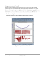
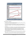
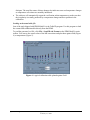
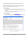
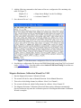
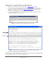
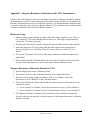
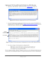
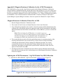
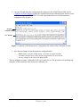
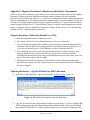
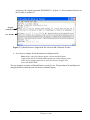
PPMS Application Note 1078-202
Magneto-Resistance Calibration Wizard for Cernox
Thermometers on the User Bridge
The Magneto-Resistance Calibration Wizard calibrates out the dependence of a thermometer
resistance on the magnetic field. It holds the PPMS system temperature constant while varying the
field to get the calibration corrections. Changes in the apparent temperature of the user thermometer
are then attributed to magneto-resistance effects. Use this wizard when you already own a Quantum
Design PPMS with a Magneto-Resistance calibrated sample chamber thermometer, and you want to
apply the same calibration to an arbitrary thermometer connected to a PPMS resistance bridge. See
Appendices for detailed procedures for VSM, TTO, ACMS and Rotator thermometers.
A thermometer on an arbitrary user-selected channel generally isn’t in good thermal contact with the
bottom of the PPMS sample chamber (where the PPMS system thermometer is located). The
temperature of the user thermometer tends to drift over time in an unknown fashion. This
circumstance is the main reason for the complexity of the wizard algorithm. To account for this
effect, the wizard offers two calibration modes that represent different tradeoffs between speed and
accuracy:
•
The fast mode assumes that the drift in the thermometer over the course of the entire set of field
steps is actually linear. It compensates by subtracting this baseline from the apparent correction
factors.
•
The high-accuracy mode only assumes that the drift in the user thermometer is linear over a
single field step. To compute the baseline, it goes back to the previous field and measures the
resistance value again. It gets a measure of the drift over the much smaller single-field step. This
mode takes substantially longer than the fast mode, but it should produce a more reliable
correction in situations where the value of the user temperature has substantial systematic
variations.
Installing the wizard
This procedure assumes that PPMS MultiVu has already been installed in the system.
1. Load the installation disk into the control PC.
2. Run setup.exe, and then follow the on-screen instructions. The MR Calibration Wizard and the
configuration files are copied into the PC hard drive.
Quantum Design
PPMS Application Note 1078-202, B-0
February 21, 2006
1
3. Start the wizard by double-clicking the
MagCalWizard icon (Figure 1) from the
directory chosen during installation or by
following the Programs > Quantum Design >
MRCalWizard link on the Windows Start
button.
Figure1. MagCalWizard icon
Running the wizard
1. Provide the wizard with information. The wizard requires some initial information on what you
want to calibrate. It guides you through the different options and runs automatically once you
have provided all the required information. There are two different levels of input that you can
provide the wizard:
•
The top-level general information is provided through the wizard graphical user interface.
You will have the opportunity to select what thermometer you want to calibrate, and the
wizard will assume default settings for its operation. This makes it possible to quickly start
calibrating with the minimum amount of knowledge about how the wizard actually works.
•
On the other hand, if more control is needed, you can also change some of the parameters
that the wizard uses such as time-out values, number of readings, temperature and field
ranges, etc. to modify its behavior. Access these settings through the MRCalWizard.ini
configuration file. It shouldn’t be necessary to change the settings in this file unless you find
that the default settings do not work in a particular case. These settings are described in the
Appendix A.
2. Choose the thermometer. Once you have chosen the thermometer, the wizard runs automatically
and unattended.
Note: If the helium level runs low, the wizard stops, sets the field to zero, and waits for the
dewar to replenish with liquid helium. When the wizard detects a low helium level, you can
instruct it to continue setting fields until the next temperature set point. Only do this if the level
of liquid is enough for the magnet to remain superconducting until the field is ramped back to
zero. Otherwise, the wizard will wait for some time before setting the field to zero and waiting.
3. The wizard begins to calibrate. It calibrates with the highest temperature first and ends at the
lowest achievable temperature. The fast mode or the high-accuracy mode steps up the field for
each temperature. Once the calibration is finished, the magneto-resistance calibration table is
computed, written, and sent to the Model 6000 controller.
4. The verification phase starts. It starts with the lowest temperature. In this mode, the field is
slowly ramped up to full field, and the deviations from the zero-field user temperature are
reported in the data file. The user temperature actually drifting away attributes to part of the
deviations (although even with this drift, the deviations are small). The maximum deviation for
each temperature is also written to the journal file.
Quantum Design
PPMS Application Note 1078-202, B-0
February 21, 2006
2
The wizard’s output files
Upon completion, the wizard has created several files and changed the state of your PPMS in several
ways.
Journal file
The wizard keeps its memory in the journal file. If the wizard is aborted in the middle of a
calibration or if there is a software/hardware failure, the journal file helps the wizard figure
where to start from when it is restarted. It keeps the calibration data for each temperature so that
it can reconstruct the calibration tables up to the point where it left them. It keeps a copy of the
bridge settings, channel mappings, and tables so that once it starts, it can put the PPMS in the
same state it was before the interruption occurred.
Data file
The data file is a log file the wizard creates so that you can see the progress of the calibration
using MultiVu. It is also helpful when diagnosing problems during calibration. The data
displayed in this file is not directly used in the creation of the tables. It writes out the following
fields:
•
the PPMS block temperature, which is always MR-corrected
•
the apparent resistance of the user thermometer
•
the temperature reported by the user thermometer (which is uncorrected during the
calibration phase and magneto-resistance calibrated during the verification phase)
•
the magnetic field
•
the percent difference between the user thermometer readings at the current field and zero
field
Table files
After finalizing the calibration phase, the wizard writes out two files. These files contain the
Magneto-Resistance calibration table, or 2D-table, in two different formats:
•
the .tab file contains the table in a format that can be plotted using MultiVu or the Table2D
program (part of the PPMS utilities).
•
the .cfg file contains a sequence of PPMS commands that can be directly downloaded to the
Model 6000 or included in the configuration file of some of the PPMS options such as
ACMS or the horizontal rotator.
Quantum Design
PPMS Application Note 1078-202, B-0
February 21, 2006
3
Interpreting the wizard’s results
Magneto-resistance calibration of a thermometer that is not in good thermal contact with the
reference being used is a difficult procedure, which requires careful interpretation of the results.
Because sudden jumps in temperature might be traced back to flow changes, for example, Quantum
Design suggests that you log diagnostics PPMS data by clicking Utilities > Log PPMS Data on the
PPMS MultiVu main toolbar. First look at the data file, and then look at the actual table file.
Looking at the data file
After a successful run, the data file should look like the example in Figure 2.
Figure 2. Example of the wizard’s data file
Quantum Design
PPMS Application Note 1078-202, B-0
February 21, 2006
4
Figure 3. A closer look at System Temperature/User Temperature from Figure 1
Notes about Figure 2 and Figure 3
•
Calibration on the last temperature started only after a long wait. This is normal. The wizard
is just trying to get to the lowest temperature possible.
•
The temperature error during the calibration phase was around 1% for large fields. This is the
normal order of magnitude for Cernox thermometers shipped with the Quantum Design
systems below 10K and above 1.8K. In 14 Tesla systems it might be up to 5% for the lowest
temperature.
•
After calibration, the errors should be 0.1- 0.2%, but the data file might report errors that are
larger than that. The user thermometer not being actively controlled, or the ACMS coil set or
rotator thermometers in poor contact with the PPMS block at the bottom of the sample
chamber, are factors that attribute to possible larger errors on the data file. Therefore,
changes in the heating or cooling power needed to keep the PPMS block at a constant
temperature might produce actual temperature changes in the user thermometer. Usually it is
easy to tell that this is the case.
•
Figure 3 zoomed in on the verification at 2.5K on the System Temperature/User Temperature
shown in Figure 1. You can see that the temperature error failed to come back to zero after
the field was ramped back down to zero. The effect of Eddy currents heating had time to
Quantum Design
PPMS Application Note 1078-202, B-0
February 21, 2006
5
dissipate. The step-like nature of those changes also indicates some real temperature changes
as temperature corrections are smoothly introduced.
•
The software will automatically repeat the verification at that temperature to make sure that
the irregularity is actually produced by a temperature change and not a problem in the
calibration.
Looking at the actual table file
One of the tools shipped with PPMS MultiVu is the Table2D program. Use this program to load
the current MR calibration table directly from the PPMS.
To read the generated .tab file, click File > Load 2D tab Format on the PPMS MultiVu main
toolbar. You can see the actual values of the MR corrections and plot them against field (Figure
4) or temperature (Figure 5).
Figure 4. A typical calibration table plotted against Field
Quantum Design
PPMS Application Note 1078-202, B-0
February 21, 2006
6
Figure 5. A typical calibration table plotted against Temperature
Notes on Figure 4 and Figure 5
•
The corrections become zero both at 20K and 0 Tesla.
•
The maximum correction might not happen at the lowest temperature because the oscillatory
magneto-resistance mandates a node in the correction value at that point.
•
The tables should look smooth. Sudden jumps in the corrections versus field or versus
temperature might indicate that the wizard failed to successfully calibrate your thermometer.
What to do if the calibration fails to produce an usable table
Sometimes the wizard might not provide an adequate calibration, and/or the residual errors are
considered to be too large. This might be attributed to the default settings for the wizard as it was
shipped from Quantum Design. They were selected to provide a reasonable compromise between
speed and accuracy but might not work under all circumstances.
This is when the configuration file might prove valuable. You can change the distribution and
number of fields and temperatures to improve reliability. Quantum Design does not recommend
using less than seven points in the field or the temperature grid. However, more fields or
temperatures should improve accuracy at the expense of a longer calibration run.
If the data seems to be particularly noisy, you can increase the calibration readings or spread
them over a longer sampling time. You can also change the calibration mode. The fast mode
might be good enough after the system has been at low temperatures for several days.
Quantum Design
PPMS Application Note 1078-202, B-0
February 21, 2006
7
Appendix A: Description of the parameters in the configuration file
Although the default settings are at the best settings and no changes are required, you can change
several parameters in the MRCalWizard.ini configuration file if you want more control over the
wizard.
Configuration file
parameters
Description
MaxField
The wizard reads the maximum field from the Model 6000, but if there
is any special circumstance that prevents reaching the maximum value,
this value can be changed. The default value of zero means that the
value will be read from the Model 6000.
MaxTemp
This is the maximum temperature that will be calibrated. The wizard
uses the sample chamber thermometer as a calibrated thermometer, so
there won’t be any gain in raising this value if the block thermometer is
not calibrated to that temperature as well. The calibration table will
actually extend beyond this temperature but only because it needs to set
the correction to zero for the highest temperature.
MinTemp
This is the minimum temperature that will be calibrated. This is usually
a value lower than the temperature the PPMS will be able to reach.
Therefore, the wizard waits some time to reach it. The operation times
out and the wizard sets what appears to be the lowest reachable and
stable temperature.
MinTempVer
Minimum temperature used during verification process. Default is set to
1.9K.
CriticalHeLevel
Because the wizard can take a long time to run, the PPMS running out
of helium and leaving the charged magnet exposed becomes a risk. To
avoid this situation, the wizard checks the helium level before setting a
new field, brings the field back to zero, and refuses to continue until the
helium is replenished. Only change this parameter if your helium level
meter is configured in a non-standard way. Otherwise, the default value
of 50% is the minimum that can be used.
Nfields
The number of field steps to take.
FieldDist
Distribution of sample field. 0 = Quadratic, 1 = Linear
Ntemps
The number of temperature steps.
VerFieldSweepRate
The verification phase of the calibration process is done as a continuous
sweep of the magnetic field at each temperature. This parameter tells the
PPMS how fast to sweep. Too fast of a sweep causes eddy current
heating to cause errors.
Quantum Design
PPMS Application Note 1078-202, B-0
February 21, 2006
8
Configuration file
parameters
Description
CalibrationMode
The wizard can run in two modes: a fast mode (0) and a high-accuracy
mode (1). In the fast mode, the field is either always increasing or
always decreasing, and then it ramps back down to zero. If an offset is
discovered at that point from the previous zero-field apparent
temperature, a linear baseline is assumed and subtracted. In the highaccuracy mode, the field is varied in a “two-steps forward, one
backward” set of steps, and the baseline is subtracted at each step to
account for non-linear behavior of the whole baseline.
EddySettlingTime
During charging and discharging of the magnet, the effect of Eddy
current heating will be noticeable in the user thermometer. This is a
fixed amount of time the system waits for the heat generated to
dissipate.
NumResMeas
At each temperature and field point, the wizard takes NumResMeas
independent resistance measurements on the User Thermometer.
Quantum Design does not recommend the use of values less than 5.
TimeBetweenMeas
This is a time between measurements of resistance you can add if you
want a more extended sampling time.
User Thermometer
2Dtable
The name of the 2D table file. (*.tab)
LogFileName
The name of the data file. (*.dat)
Journal File
The name of the journal file. (*.jrn)
Quantum Design
PPMS Application Note 1078-202, B-0
February 21, 2006
9
Appendix B: Magneto-Resistance Calibration for the VSM Thermometer
VSM Option uses the CAN Module for its thermometry, it does not use the User Bridge on the
Model 6000. Therefore, the following modifications will need to be followed in order to use the
Magneto-Resistance Calibration Wizard with the VSM thermometer.
Hardware installation
1. Install the VSM coil set to be calibrated into the PPMS sample chamber and a baffle
assembly without the charcoal holder. The VSM head and Sample Tube are not necessary for
this procedure.
2. Connect the gray lemo resistivity cable between the gray lemo port on the back of the PPMS
probe head and the P1 User Bridge on the Model 6000.
Software Configuration
1. Open the Coil-XXX.cfg file located under \\QdPpms\Vsm\Calibration. Copy Table 25 from
the coil configuration file as indicated in Figure 6 and paste into a new Notepad page.
Figure 6. VSM coil configuration file
Quantum Design
PPMS Application Note 1078-202, B-0
February 21, 2006
10
2. Add the following commands at the bottom of the new configuration file containing only
table 25 (Figure 7):
Mapdat 25, 4;
<< Maps data to Bridge 1 on the User Bridge
Tblmod 25, 1;
<< Activates Channel 25
3. Save the new file as a *.cfg.
Figure 7. VSM thermometer configuration file to be sent to the Model 6000
4. Send the new configuration file down to the PPMS Model 6000 using RomCfg32.exe located
under \\QdPpms\Tools. From the toolbar select Send to PPMS\Send Config to send the new
configuration file you created above.
Magneto-Resistance Calibration Wizard For VSM
1. Run the Magneto-Resistance Calibration Wizard.
2. The wizard will ask for Auto or Manual Detection. Select Manual Detection.
3. Then select which bridge channel to calibrate. Select User Channel 1.
4. The wizard will then ask which GetDat channel to calibrate. Select Channel 25.
5. The Magneto-Resistance Calibration Wizard will then run the calibration automatically.
Proceed to the next step once the verification process of the Magneto-Resistance Calibration
Wizard is complete.
Quantum Design
PPMS Application Note 1078-202, B-0
February 21, 2006
11
Updating the Coil *.cfg File With the New MR Calibration
1. Open the new MR calibrated *.cfg file located under \\QdPpms\Tools. (Figure 8)
2. Copy the 2D table from the configuration file (Do not copy the command: TBLMODE25, 2)
and paste in the VSM Coil-XXX.cfg file (\\QdPpms\VSM\Calibration) under the original
thermometer calibration table. (Figure 9)
3. As in Figure 9, add `MR Therm = ` at the beginning of the 2D table. Again ensure that the
command: TBLMODE 25,2 is not present.
Figure 8. New MR Calibrated configuration file with 2D table
Original
Calibration Table
New 2D table
Figure 9. Updated VSM coil Configuration file with new MR Calibrated 2D table
4. Save the new changes to the coil configuration file.
The new magneto-resistance calibrated coil set is ready for use. The procedures for installing and using
the VSM Option remain the same for the new calibrated coil set.
Quantum Design
PPMS Application Note 1078-202, B-0
February 21, 2006
12
Appendix C: Magneto-Resistance Calibration for the TTO Thermometer
Similar to the VSM Option, in order to use the Magneto-Resistance Calibration Wizard to calibrate
the thermometers on the TTO puck, some specific procedures need to be followed. In addition, the
Hot and Cold thermometers have to be calibrated separately. The Hot thermometer calibration table
is stored on Channel 21 and read on User Bridge Channel 1. The Cold thermometer calibration table
is stored on Channel 22 and read on User Bridge Channel 2.
Hardware set-up
1. Mount a Copper mounting bridge assembly (4084-608) sample supplied in your TTO user
kit. Connect the TTO heater and thermometer shoes to it. This copper sample thermally
“shorts” the TTO shoes to the puck.
2. Install the puck and a baffle assembly without the charcoal holder into the sample chamber.
3. Attach the appropriate TTO gray lemo cable and other required cable connections as
discussed in Appendix A.2 Installing Thermal Transport Hardware of the TTO User’s
Manual.
4. Activate the TTO Option. This will send the proper thermometer calibration tables to the
Model 6000.
5. Before starting the MR Calibration Wizard, deactivate the TTO option in order to prevent
any interference that might occur between the option and the calibration wizard.
Magneto-Resistance Calibration Wizard For TTO
1. Run the Magneto-Resistance Calibration wizard.
2. The wizard will ask for Auto or Manual Detection. Select Manual Detection.
3. Then select which bridge channel to calibrate. Select User Channel 1 for the Hot
thermometer or User Channel 2 for the Cold thermometer.
4. The wizard will then ask which GetDat channel to calibrate (Only one thermometer can be
calibrated at a time):
•
If you selected User Channel 1 for the Hot thermometer in Step 3, select Channel 21.
•
If you selected User Channel 2 for the Cold thermometer in Step 3, select Channel 22.
5. The Magneto-Resistance Calibration Wizard will then run the calibration automatically.
Proceed to the next step once the verification process of the Magneto-Resistance Calibration
Wizard is complete.
Quantum Design
PPMS Application Note 1078-202, B-0
February 21, 2006
13
Updating the TTO ThermXXX.cfg File With the New MR Calibration
1. Open the new MR calibrated *.cfg file located under \\QdPpms\Tools. (Figure 10)
Figure 10. MR calibrated configuration file for the TTO Hot thermometer
2. Copy the 2D table from the configuration file (Do not copy the command: TBLMODE 21,2)
and paste in the TTO ThermXXX.cfg file (\\QdPpms\ThermalTransport\Calibration) under the
original thermometer calibration table. (Figure 11)
Original
Calibration Table
New 2D table
Figure 11. Updated TTO Hot thermometer Configuration file with new MR Calibrated 2D table
3. Save the new changes for the thermometer configuration file.
Note: Before using the TTO option, reactivate the option anytime you
make changes to any of the option configuration files in order for the
new changes to be sent to the Model 6000.
The new magneto-resistance calibrated TTO puck is ready for use after calibrating both thermometers.
The procedures for installing and using the TTO Option remain the same for the new calibrated puck.
Quantum Design
PPMS Application Note 1078-202, B-0
February 21, 2006
14
Appendix D: Magneto-Resistance Calibration for the ACMS Thermometer
The ACMS allows you to use the Auto Detection option in the Magneto-Resistance Calibration
Wizard. Hardware installation basically remains the same for the options as if you were setting up to
perform AC measurements, except for the Sample Transport. The Sample Transport is not necessary
in order to perform the calibration. Refer to the ACMS Option User’s Manual for detailed procedures
for installation. The ACMS thermometer calibration table is stored on Channel 25 and read on
System Bridge 4 (System Bridge 4 resistance values are reported on Channel 42 or Spare Therm).
Magneto-Resistance Calibration Wizard For ACMS
1. Run the Magneto-Resistance Calibration wizard.
2. The wizard will ask for Auto or Manual Detection. Select Auto Detection.
3. You will then be prompted by the wizard to activate the option with the thermometer to be
calibrated. By activating the option, the appropriate table will be downloaded to the Model
6000 and channel activated for the wizard to detect. Select OK once you have activated the
option.
Note: When activating the ACMS option, it is normal to get servo
connection errors since the sample transport was not installed. Select OK
and allow the option to run in simulation mode. The importance of
activating the ACMS is the initialization of the coil thermometer.
4. The wizard then detects and verifies the option thermometer is operating properly. After
checking the thermometer, the wizard will let you know that it is ready to start MR
calibrating the thermometer. Before starting the calibration procedure, the wizard
recommends to deactivate the option that is being calibrated in order to prevent any
interference that might occur between the option and the calibration wizard. Once the
option is deactivated, select OK.
5. The Magneto-Resistance Calibration Wizard will then run the calibration automatically.
Proceed to the next step once the verification process of the Magneto-Resistance Calibration
Wizard is complete.
Updating the ACMS Thermometer *.cfg File With the New MR Calibration
1. Open the new MR calibrated *.cfg file located under \\QdPpms\Tools. (Figure 12)
Figure 12. MR calibrated configuration file for the ACMS
Quantum Design
PPMS Application Note 1078-202, B-0
February 21, 2006
15
2. Copy the 2D table from the configuration file and paste in the ACMS Therm-XXX.cfg file
(\\QdPpms\ACMS\Calibration) under the original thermometer calibration table. Ensure to also
include the command: TBLMODE 25,2 when copying the table over to the thermometer
configuration file. (Figure 13)
Original
Calibration Table
New 2D table
Figure 13. Updated ACMS thermometer Configuration file with new MR Calibrated 2D table
3. Save the new changes for the thermometer configuration file.
Note: Before using the ACMS option, reactivate the option anytime
you make changes to any of the option configuration files in order for
the new changes to be sent to the Model 6000.
The new magneto-resistance calibrated ACMS coil is ready for use. The procedures for installing and
using the ACMS remain the same for the new calibrated coil.
Quantum Design
PPMS Application Note 1078-202, B-0
February 21, 2006
16
Appendix E: Magneto-Resistance Calibration for the Rotator Thermometer
Similar to the ACMS, the Rotator option allows you to use the Auto Detection option in the MagnetoResistance Calibration Wizard. Hardware installation remains unchanged for this calibration
procedure. Refer to the Rotator Option User’s Manual for installation procedures and downloading the
rotator configuration files. The rotator thermometer calibration table is stored on channel 23 and read
off of the User Bridge Channel 1 unless using in conjunction with the ACT option. When the Rotator
option is being used with the ACT, System Bridge Channel 4 reads the rotator thermometer (System
Bridge 4 resistance values are reported on Channel 42 or Spare Therm). However, for the following
procedure, the ACT option will not be necessary.
Magneto-Resistance Calibration Wizard For ACMS
1. Run the Magneto-Resistance Calibration wizard.
2. The wizard will ask for Auto or Manual Detection. Select Auto Detection.
3. You will then be prompted by the wizard to activate the option with the thermometer to be
calibrated. Download the rotator configuration file to the Model 6000 using RomCgf32.exe
if you have not already done so. Select OK once you have downloaded the file.
4. The wizard then detects and verifies the option thermometer is operating properly. After
checking the thermometer, the wizard will let you know that it is ready to start MR
calibrating the thermometer. Ignore the recommendation to deactivate the option, it does no
apply to the rotator option, and select OK.
5. The Magneto-Resistance Calibration Wizard will then run the calibration automatically.
Proceed to the next step once the verification process of the Magneto-Resistance Calibration
Wizard is complete.
Updating the Rotator *.cfg File With the New MR Calibration
4. Open the new MR calibrated *.cfg file located under \\QdPpms\Tools. (Figure 14)
Figure 14. MR calibrated configuration file for the Rotator
5. Copy the 2D table from the configuration file and paste in the rotator *.cfg file (\\QdPpms\HRXXX\Configuration) under the original thermometer calibration table. Ensure to also include
the command: TBLMODE 23,2 when copying the table over to the rotator configuration file
Quantum Design
PPMS Application Note 1078-202, B-0
February 21, 2006
17
and remove the original command TBLMODE 23,1 (Figure 15). This command will activate
the 2D table on channel 23.
Original
Calibration Table
New 2D table
Figure 15. Updated Rotator Configuration file with new MR Calibrated 2D table
6. Save the new changes for the thermometer configuration file.
Note: Before using the Rotator option, redownload the Rotator
configuration file to the Model 6000 anytime you make changes to any
of the option configuration files in order for the new changes to be
sent to the Model 6000.
The new magneto-resistance calibrated Rotator is ready for use. The procedures for installing and
using the Rotator remain the same for the new calibrated option.
Quantum Design
PPMS Application Note 1078-202, B-0
February 21, 2006
18