1
H
C
O
C
.,
D
T
L
TE
R
AUser's Manual
T
S
A
V
NovaCLB-Screen-Full-screen Calibration
N
A
'
I
X
www.novastar-led.com
O
N
System
Rev1.0.0 NS140000002
1
Full-Screen Calibration System User's Manual
Contents
1
INTRODUCTION .....................................................................................................................................................5
1.1
WHY PIXEL LEVEL CALIBRATION ................................................................................................................................... 5
1.2
CORE ADVANTAGES OF NOVACLB-SCREEN ..................................................................................................................... 6
1.3
SYSTEM STRUCTURE ................................................................................................................................................... 8
D
T
L
2
AUTHOR MANAGE .................................................................................................................................................9
3
FULL-SCREEN CALIBRATION .................................................................................................................................10
.,
3.1
OPERATION PROCESS................................................................................................................................................ 10
3.2
CALIBRATION INITIALIZATION ..................................................................................................................................... 12
H
C
O
C
3.2.1
Calibration Mode ........................................................................................................................................... 12
3.2.2
Network Settings ............................................................................................................................................ 13
3.2.3
Database ........................................................................................................................................................ 17
3.2.4
Screen Information ......................................................................................................................................... 18
3.2.5
Original Brightness and color Measurement ................................................................................................. 21
3.2.6
Target Brightness and Color ........................................................................................................................... 26
3.3
R
A
TE
T
S
A
V
PARTITION CALIBRATION ........................................................................................................................................... 36
O
N
3.3.1
Partitions ........................................................................................................................................................ 36
3.3.2
Connect To Camera ........................................................................................................................................ 44
3.3.3
Camera Parameters ....................................................................................................................................... 45
3.3.4
Partition Calibration ....................................................................................................................................... 48
3.3.5
Partition Boundary ......................................................................................................................................... 58
3.4
N
A
'
I
X
MODIFY SCREEN ..................................................................................................................................................... 59
3.4.1
Sub screen ...................................................................................................................................................... 61
3.4.2
Check The Database ....................................................................................................................................... 62
3.4.3
New Revise Database ..................................................................................................................................... 63
3.4.4
Connect To Camera ........................................................................................................................................ 64
3.4.5
Camera Parameters ....................................................................................................................................... 64
3.4.6
Full-screen Revise ........................................................................................................................................... 64
www.novastar-led.cn
2
Full-Screen Calibration System User's Manual
4
MODIFY DARK OR BRIGHT LINES ..........................................................................................................................65
4.1
INITIALIZATION ........................................................................................................................................................ 66
4.1.1
Network Settings ............................................................................................................................................ 67
4.1.2
Database ........................................................................................................................................................ 68
4.1.3
Calibration Information .................................................................................................................................. 69
4.2
5
MODIFY LINES ........................................................................................................................................................ 70
4.2.1
Partition ......................................................................................................................................................... 70
4.2.2
Camera ........................................................................................................................................................... 71
4.2.3
Modify Lines ................................................................................................................................................... 73
.,
D
T
L
MODULE CALIBRATION ........................................................................................................................................81
5.1
O
C
INITIALIZATION ........................................................................................................................................................ 81
H
C
5.1.1
Network setting.............................................................................................................................................. 82
5.1.2
Database ........................................................................................................................................................ 84
5.1.3
Screen Info...................................................................................................................................................... 85
5.2
R
A
TE
REPLACE MODULE................................................................................................................................................... 86
T
S
A
5.2.1
Module location ............................................................................................................................................. 86
5.2.2
Connect to Camera......................................................................................................................................... 91
5.2.3
Camera Parameters ....................................................................................................................................... 91
5.2.4
Module calibration ......................................................................................................................................... 92
V
O
N
6
CALIBRATION INTERRUPTION (SEARCHING LED POSITION FAILED) .................................................................... 102
7
FULL SCREEN DATA MERGING ............................................................................................................................ 108
8
FULL SCREEN TO CABINET .................................................................................................................................. 111
N
A
8.1
'
I
X
8.2
OPERATION PROCEDURE ......................................................................................................................................... 111
OPERATION INSTRUCTION ....................................................................................................................................... 112
8.2.1
Import database........................................................................................................................................... 112
8.2.2
Draw topological graph ............................................................................................................................... 114
8.2.3
Set resolution of each cabinet ...................................................................................................................... 114
8.2.4
Number the cabinet ..................................................................................................................................... 119
8.2.5
Set target database ...................................................................................................................................... 123
www.novastar-led.cn
3
Full-Screen Calibration System User's Manual
8.2.6
File path ....................................................................................................................................................... 123
8.2.7
Switch ........................................................................................................................................................... 124
9
SCREEN UPDATE TARGETS .................................................................................................................................. 124
10
NOVACLB-SCREEN HELP ..................................................................................................................................... 126
11
10.1
NETWORK SETTINGS .............................................................................................................................................. 126
10.2
LCT MONITOR SETTINGS ........................................................................................................................................ 128
10.3
PRINCIPLE OF BRIGHTNESS AND COLOR CALIBRATION ................................................................................................... 129
10.4
CAMERA OPERATING SKILLS .................................................................................................................................... 131
10.5
SUBAREA IMAGING OPERATING SKILLS....................................................................................................................... 133
10.6
LARGE PARTITION OPERATING TECHNIQUE .................................................................................................................. 134
10.7
STEPS TO CHECK CALIBRATION EFFECTS ..................................................................................................................... 135
10.8
WATER RIPPLE IN FULL-SCREEN CALIBRATION ............................................................................................................. 137
H
C
O
C
.,
D
T
L
TE
EDITION STATEMENT.......................................................................................................................................... 138
R
A
T
S
A
V
N
A
O
N
'
I
X
www.novastar-led.cn
4
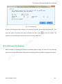
Full-Screen Calibration System User's Manual
1 Introduction
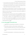
1.1 Why Pixel Level Calibration
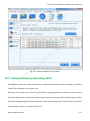
Brightness / Color uniformity is of the most important factors that affect the image quality of a full
color LED display. Because of the limitations of the manufacturing process, including system
D
T
L
structure design, LED lights selection, electronic components welting, system cooling, LED
brightness decaying and many others, LED displays suffer the brightness / color uniformity loss,
which is also the most serious problem of this field.
O
C
.,
Facing this fact, Nova pixel level calibration system does not intervene the manufacturing
H
C
processing of a LED display to reduce its brightness / color uniformity. Instead, it performs
TE
brightness / color adjustment to the display after it has been completely produced. By adjusting
R
A
the brightness / color of each LED light according to the software analytical results from the
T
S
A
measured brightness / color values of the LED lights, Nova pixel level calibration system can help
V
the LED display acquiring perfect uniformity.
N
A
O
N
'
I
X
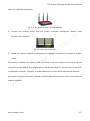
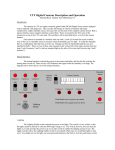
Fig.1-1 The LED display effects comparison before and after calibration
NovaCLB is applicable for the following two occasions:
www.novastar-led.cn
5
Full-Screen Calibration System User's Manual
Factory single cabinet pixel level calibration (Factory calibration). Correct each cabinet on the
production line to ensure good brightness / color uniformity of the cabinets when produced.
Field LED display pixel level calibration (Full-screen calibration). Perform calibration for a LED
display at where it locates to improve its brightness / color uniformity.
Factory calibration is more efficient and lower in cost than Full-screen calibration. But for cabinets
of which the LED lights optical axis directions consistency is not well managed, results of factory
D
T
L
calibration will not be as good as that of filed calibration. When doing factory calibration, the
matching NovaCLB-Cabinet is needed.
O
C
.,
Full-screen calibration requires engineers to be presence and Full-screen installation of calibration
H
C
instruments. And what’s more, Full-screen calibration can only be performed only at night when
TE
it’s dark. Despite its complexity and low efficiency (compared with factory calibration),
R
A
Full-screen calibration can greatly improve the brightness / color uniformity of a LED display and
T
S
A
thus results in amazing image quality of the display. When doing Full-screen calibration, the
matching NovaCLB-Screen is needed.
V
1.2 Core AdvantagesO
of NovaCLB-Screen
N
N
'A
I
X
Camera calibration technology enabling accurate brightness / color measurement;
Precise calibration coefficients up to 16bits resulting in outstanding calibration
performance with brightness variation less than 1% and color variation less than 0.003;
Be capable of eliminating color diversity of LED lights from different manufacturing
batches;
Be capable of eliminating brightness / color diversity between subareas or cabinets;
www.novastar-led.cn
6
Full-Screen Calibration System User's Manual
Arc shape and irregular shape LED display calibration supported;
Oblique cabinet calibration on production lines supported;
Supporting automatic calibration for the replaced module;
Perfect compatible with LED control systems;
Specific calibration algorithm enabling perfect calibration for low gray level range;
Close loop intelligent calibration resulting in easy and high efficiency calibration. One LED
display, one person; 25 minutes,600K pixels;
O
C
.,
D
T
L
Adopt RGB to begin the collection mechanism and collection-processing mechanism at
H
C
the same time during the calibration process so as to improve the efficiency;
T
S
A
transition between partitions;
R
A
TE
Support correction to the boundary difference between partitions so as to enable smooth
No extra power supply required.
V
N
A
O
N
'
I
X
www.novastar-led.cn
7
Full-Screen Calibration System User's Manual
1.3 System structure
H
C
R
A
O
C
.,
D
T
L
TE
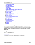
Fig. 1-2 System structure(NovaLCT)
T
S
A
V
N
A
O
N
'
I
X
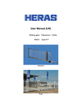
Fig. 1-3 System structure(NovaPro)
www.novastar-led.cn
8
Full-Screen Calibration System User's Manual
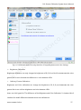
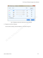
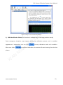
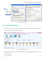
2 Author manage
NovaCLB-Screen adopts the management methods of encryption lock and authorized file binding
authorization; and every dongle corresponds to one authorized file, which is combined with the
file authorization.
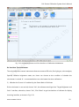
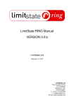
When the software is operated, the following window will appear; click OK to open the software,
where the software is not authorized and it cannot be used normally.
H
C
O
C
.,
D
T
L
TE
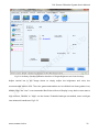
Insert dongle to the USB port of the computer; click menus "Author"→“Author manage” on the
R
A
main interface; enter to the Authorization manage window, click
T
S
A
to import the
authorized file (in the disk) corresponding to the dongle.
V
Multiple authorized file can be imported, thus, the software (after being copied to other
O
N
computers) can be used by inserting the dongle.
N
A
'
I
X
www.novastar-led.cn
9
Full-Screen Calibration System User's Manual
H
C
O
C
.,
D
T
L
TE
Fig.2-1Authorization management
R
A
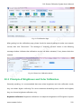
3 Full-Screen Calibration
3.1 Operation process
T
S
A
O
N
V
If normal partition mode is selected during partition calibration, the following procedure may be
N
A
adopted to perform calibration (wherein, ”Eliminate the boundaries of the partitions“is optional.
'
I
X
In case of partition correction with good results, modify screen may be omitted):
Initialization
Cablibration(Normal partition)
“Partition Boundary”is not the
required option
This step can be omitted if the
effect is good after partition
calibration
Modify
Screen
Fig. 3-1 Software Operation Process (One)
If large partition mode is selected during partition correction, the following process should be
www.novastar-led.cn
10
Full-Screen Calibration System User's Manual
adopted to perform calibration:
Cablibration(Large partition)
The software defaults to
eliminate the boundary
Initialization
This step can be omitted if the
effect is good after partition
calibration
Modify
Screen
Fig. 3-2 Software Operation Process (Two)
Initialization
D
T
L
This interface is designed to initialize a series of calibration parameters, including the
O
C
.,
communication settings, databases, display information, the original brightness / color
parameters and the expected brightness / color, etc.
Partitions Calibration
H
C
TE
This interface is committed to guide customers to perform pixel level calibration on each LED light,
which signally improve the display uniformity.
R
A
T
S
A
Partition Calibration can be divided into normal partition and large partition. Calibrated area of
V
the large partition is several times of the normal partition, thus the large partition is applicable for
O
N
calibration of large display screen.
N
A
Partition Boundary
'
I
X
Eliminate the differences among partitions.
Modify screen
When the partition calibration is totally completed, then it comes to the modify screen. modify
screen perfectly eliminate the differences among the partitions, which can make the screen be a
flawless whole.
www.novastar-led.cn
11
Full-Screen Calibration System User's Manual
3.2 Calibration Initialization
Calibration
Mode
Network
Setting
Database
Connect
NovaCLBScreen and
NovaLCT or
NovaPro
through the
network
Choose
Full-screen
or Module
Screen info
New or
load
calibration
database
Set
parameters
of display
Original Value
Set
expected
brightness/
chroma
parameters
of display
Targeted Value
Set
expected
brightness/
chroma
parameters
of display
Fig. 3-3 Flow chart of Calibration Initialization
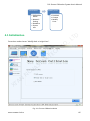
3.2.1 Calibration Mode
H
C
R
A
O
C
.,
D
T
L
TE
T
S
A
V
N
A
O
N
'
I
X
Fig. 3-4 Choose calibration mode
www.novastar-led.cn
12
Full-Screen Calibration System User's Manual
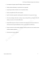
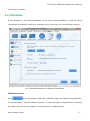
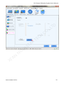
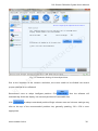
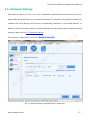
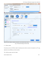
3.2.2 Network Settings
H
C
R
A
O
C
.,
D
T
L
TE
T
S
A
V
N
A
O
N
Fig. 3-5 Network Settings Interface of Calibration Initialization
'
I
X
Control system Connection
NovaCLB-Screen must be used cooperate with Control system (NovaLCT or Novapro) to
calibration the display.
NovaLCT Connection
Ensure that the NovaCLB-Screen computer can communicate with the NovaLCT computer well, fill
the IP and port (The default is 8080, can be modified ) from NovaLCT in the location of IP and port
from NovaCLB-Screen, then click "Connect" button. Fig.3-6 will show up, and the Connection is
www.novastar-led.cn
13
Full-Screen Calibration System User's Manual
done.
H
C
R
A
O
C
.,
D
T
L
TE
T
S
A
V
N
A
O
N
'
I
X
www.novastar-led.cn
14
Full-Screen Calibration System User's Manual
H
C
R
A
O
C
.,
D
T
L
TE
T
S
A
V
O
N
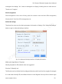
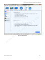
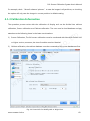
Fig. 3-6 Prompt message from NovaLCT when connection is successful
If connection is failed, users could click "Network Setting Guide" showed in fig.3-6.
N
A
'
I
X
NovaPro Connection
Ensure that the NovaCLB-Screen computer can communicate with the NovaPro well, input the IP
and port (The port is set to 5200 ) of NovaPro or NovaCLB-Screen, then click "Connect" button.
Fig.3-7 will show up, and the Connection is done.
www.novastar-led.cn
15
Full-Screen Calibration System User's Manual
H
C
R
A
O
C
.,
D
T
L
TE
T
S
A
V
O
N
Fig. 3-7 Prompt message from NovaPro when connection is successful
Screen Resolution
N
A
'
I
X
The resolution of display is the width and height in the pixel level.
After NovaCLB-Screen is connected with NovaLCT or NovaPro successfully, the bottom of
interface will show display count and the corresponding resolution of connected NovaLCT or
NovaPro. Users could choose display number as needed, the default value is the first one.
Module Size
Check “Module size same” and set the module width and module height of module if the size of
all module are same. The function of Modify dark or bright lines will be not supported if the size
www.novastar-led.cn
16
Full-Screen Calibration System User's Manual
of module is not same.
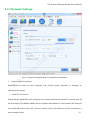
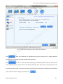
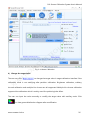
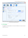
3.2.3 Database
A new database or the existing database can be used; and the database is used for saving
information of calibration coefficient, calibration time, screen size, etc. it shall be kept properly.
H
C
R
A
O
C
.,
D
T
L
TE
T
S
A
V
N
A
'
I
X
O
N
Fig. 3-8 Database Interface of Calibration Initialization
Calibration Pictures
Click
to set the position where the collected images are saved during calibration.
For example, check “Save all subareas' pictures” to save the images in all partitions; un-checking
the option will only save the images in current partition in default setting.
www.novastar-led.cn
17
Full-Screen Calibration System User's Manual
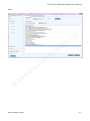
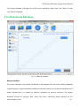
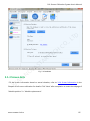
3.2.4 Screen Information
H
C
R
A
O
C
.,
D
T
L
TE
T
S
A
V
N
A
O
N
Fig. 3-9 Display Information Interface of Calibration Initialization
'
I
X
Ambient Brightness
Ambient Brightness is the brightness of surrounding environment when calibrating. In general,
the brightness is "low" at night, its "High" at nightfall or cloudy day. It is unsuited to calibrate in
sunny day.
Screen Type
The type of Screen can be divided as "Regular", "Arc", "Irregular". "Regular" means it is a common
www.novastar-led.cn
18
Full-Screen Calibration System User's Manual
rectangular lane display. "Arc" means a rectangular arc display, including inner arc and outer arc.
The else are "Irregular".
Pixel Arrangement
Pixel Arrangement is the count of every pixel, the common ones are three LEDs arrangement,
Virtual pixel of 3 led, four LEDs arrangement, etc.
Advanced settings
D
T
L
The above four terms are the basic parameters information of display. Click "Advanced Settings"
button to get in advanced settings interface.
H
C
R
A
O
C
.,
TE
T
S
A
V
N
A
'
I
X
O
N
Fig. 3-10 Advanced Settings Interface of Display Information
Width and Height Ratio of Template
Identify template for LED, default values are suggested.
Direction To Identify Led
The Direction can be divided into four diagonal directions which are from four angles of rectangle.
It is used when identify LED, the default direction is the diagonal from top left to bottom right.
www.novastar-led.cn
19
Full-Screen Calibration System User's Manual
When the LED of top left angle can't display normally, please change the direction. For example,
users try to identify LED from bottom right when the first row or the first column is covered.
Dead LEDs Ratio Allowed
If the LEDs which can't be identified in calibrating zone is greater than the ratio, the calibrating
flow would stop and some prompt messages will be presented. Please be sure whether the "dead
lights are too much" or "some LED pixels are covered" is appeared. If the problem can't be solved,
users could turn up this ratio to calibrate forcibly.
Spectrum Revise Mode
O
C
.,
D
T
L
In normal conditions, users could choose mode 1. In Special conditions, if there is still some spots
H
C
uniformed in the screen, users could choose mode 2 or mode 3.
Unit size
R
A
TE
If pixels of columns and rows of a LED display can be divided by 8, please select 8*8. If pixels of
T
S
A
columns and rows of a LED display can be divided by 10, please select 10*10.
V
N
A
O
N
'
I
X
www.novastar-led.cn
20
Full-Screen Calibration System User's Manual
3.2.5 Original Brightness and color Measurement
H
C
R
A
O
C
.,
D
T
L
TE
T
S
A
Fig. 3-11 Flow chart of Measure Original Brightness and Color
V
O
N
Original brightness and color is the original brightness and color parameters information of the
display to be calibrated. It’s important to set these parameters correctly for the result of
calibration.
1)
N
A
'
I
X
Whether the Colorimeter is Carried
www.novastar-led.cn
21
Full-Screen Calibration System User's Manual
H
C
R
A
O
C
.,
D
T
L
TE
T
S
A
V
O
N
Fig. 3-12 Original Brightness and Color Interface of Calibration Initialization
Do You Have The Colorimeter
N
A
'
I
X
The colorimeter here means instruments that can measure LED color, like: light gun, color analyzer,
Spectral radiation brightness meter, etc. Users can choose as the condition of whether the
colorimeter is carried. It’s recommended to use colorimeter the when calibration.
2)
Whether the Screen is Combined by the Same Batch of Cabinets
If the colorimeter is not carried, choose "No", the software would get into "Target Brightness and
Color" interface, otherwise, choose "Yes", Click "Next" to get into batches of cabinets for display
choosing interface, as shown in Fig 3-13.
www.novastar-led.cn
22
Full-Screen Calibration System User's Manual
H
C
R
A
O
C
.,
D
T
L
TE
T
S
A
V
O
N
Fig. 3-13 Batches of Cabinets for Display Choosing Interface
The Same Batch
N
A
'
I
X
The screen is combined by the same batch of cabinets.
Different Batches
The screen is combined by different batches of cabinets. The difference between cabinets is clear.
In this condition, users need to measure brightness and color of different batches of cabinets.
After choosing, Click "Next", get into the detail measurement interface.
Screen is Combined by the Same Batch of Cabinets
www.novastar-led.cn
23
Full-Screen Calibration System User's Manual
H
C
R
A
O
C
.,
D
T
L
TE
T
S
A
V
O
N
Fig. 3-14 Measure Brightness and Color of the Screen Combined by the Same Batch of Cabinets
Measuring Area Choosing
N
A
'
I
X
This measuring zone means the alight zone when measuring the brightness and color. It’s aiming
at locating measuring zone problem when the screen is combined by different kind of cabinets.
Users can change the size and location of measuring zone by click the four direction buttons and
the middle button in the interface.
Brightness and Color Information
After Adjusting the measuring zone, users can click "Red", "Green", "Blue" buttons left to the table
to control the display color. Then, users can measure brightness, Cx, and Cy to complete
www.novastar-led.cn
24
Full-Screen Calibration System User's Manual
measurement.
3)
Screen is Combined by different Batches of Cabinets
H
C
R
A
O
C
.,
D
T
L
TE
T
S
A
V
N
A
O
N
'
I
X
Fig. 3-15 Measure Brightness and Color of the Screen Combined by Different Batches of Cabinets
Measuring Zone Adjustment
It's same as the screen combined by the same batch of cabinets.
Batch Adding
In the software, the screen is combined by two batches cabinets by default, users can click "Add
Batch" "button to add Batches.
www.novastar-led.cn
25
Full-Screen Calibration System User's Manual
Get Common Color Gamut
"Get Common Color Gamut" is the common part of measuring color gamut of different batches, is
the key to achieve consistent uniformity. After complete measuring brightness and color of
different batches of cabinets, users should click "Get Common Color Gamut" button.
Thus far, original brightness and color information of display is completed. Click "Next" to get into
"Target Brightness and Color" settings.
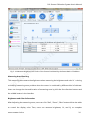
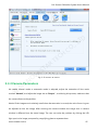
3.2.6 Target Brightness and Color
H
C
R
A
O
C
.,
D
T
L
TE
T
S
A
V
N
A
O
N
'
I
X
Fig. 3-16 Flow chart of Original Brightness and Color Settings
1)
Calibration Mode Choosing
www.novastar-led.cn
26
Full-Screen Calibration System User's Manual
H
C
R
A
O
C
.,
D
T
L
TE
T
S
A
V
O
N
Fig.3-17 Calibration Mode Choosing Interface of Target Brightness and Color Settings
Brightness Calibration
N
A
'
I
X
Brightness calibration can only change the brightness of R, G, B, and it will not attenuate the color
gamut. But it can't eliminate the difference in color between LEDs.
Ordinary Chroma Calibration
Brightness and Color calibration can change the brightness of R, G, B, and attenuate the color
gamut. But it can uniform brightness and color between LEDs.
Users can click hyperlink "The difference of the Brightness and Color Calibration" in bottom left of
interface for detail differences between these two calibrations.
www.novastar-led.cn
27
Full-Screen Calibration System User's Manual
Multiple bin Chroma Calibration
Multiple bin chrome calibration is mainly used for adjusting the brightness difference after
multi-batch of lamps or lamp panels have been mixed.
After choosing, click "Next" button.
2)
Brightness Calibration
If users choose "brightness calibration", it will show as Fig.3-18.
H
C
R
A
O
C
.,
D
T
L
TE
T
S
A
V
N
A
O
N
'
I
X
Fig.3-18 Brightness Calibration Interface of Target Brightness and Color Settings
Adjust vertical bar in the image above, choose an appropriate brightness attenuation value, the
recommended value is 92%. This adjustment is the common attenuation of R, G, B. If the
www.novastar-led.cn
28
Full-Screen Calibration System User's Manual
separated adjustment is needed, check "Enable Advance" and click "Advanced Adjustment"
button. Then, it gets into advanced settings interface Fig.3-19 and Fig.3-20.
H
C
R
A
O
C
.,
D
T
L
TE
T
S
A
V
N
A
O
N
'
I
X
Fig.3-19 Brightness Attenuation Adjustment without Colorimeter
www.novastar-led.cn
29
Full-Screen Calibration System User's Manual
O
C
.,
D
T
L
Fig.3-20 Brightness Attenuation Adjustment with Colorimeter
3)
H
C
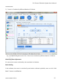
Brightness and Color Calibration
TE
If users choose "Ordinary Chroma Calibration", it will show as Fig.3-21.
R
A
T
S
A
V
N
A
O
N
'
I
X
www.novastar-led.cn
30
Full-Screen Calibration System User's Manual
H
C
R
A
O
C
.,
D
T
L
TE
T
S
A
V
Fig.3-21 Ordinary Chroma Calibration Interface of Target Brightness and Color Settings
O
N
Adjust vertical bar in the image above to simply adjust the brightness and color, the
N
A
recommended value is 90%. The color gamut attenuation can be divided into three grades: Low,
'
I
X
Middle, High, the "Low" is recommended. But if the uniform of display is very bad or users want a
high uniform, "Middle" or "High" can be chosen. If detailed settings are needed, users could get
into advanced interface as Fig.3-22.
www.novastar-led.cn
31
Full-Screen Calibration System User's Manual
H
C
R
A
O
C
.,
D
T
L
TE
T
S
A
V
N
A
O
N
'
I
X
www.novastar-led.cn
32
Full-Screen Calibration System User's Manual
H
C
R
A
O
C
.,
D
T
L
TE
T
S
A
V
O
N
Fig.3-22 Advanced Settings Interface of Ordinary Chroma Calibration
N
A
'
I
X
In the image above, users can adjust target brightness and color value by the
on the
right, also users can input values in the textbox directly. Recommend using the first method
After adjustment, click
button to look up the current brightness and color value in CIE 1931
Color Diagram.
www.novastar-led.cn
33
Full-Screen Calibration System User's Manual
H
C
R
A
O
C
.,
D
T
L
TE
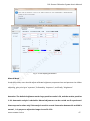
Fig.3-23 Measuring and Target Color Gamut in CIE 1931 Color Diagram
T
S
A
Original Color Gamut
V
It is corresponding to "Original Brightness and Color" in software.
O
N
Targeted Color Gamut
N
A
It is corresponding to "Target Brightness and Color" in software.
'
I
X
The white triangle in the image is corresponding to measuring color gamut, the black triangle is
corresponding to target color gamut. To realize the uniformity after calibration, the target color
gamut should less than measuring color gamut. From the image above, users can get the
attenuation of color gamut. Users can also click the right mouse button in Color Diagram to
choose adding the color coordinate to "Target Brightness and Color" value.
The former method is recommended.
www.novastar-led.cn
34
Full-Screen Calibration System User's Manual
Users can also check“Color Temperature”and directly enter an appropriate color temperature
value,or drag the bar to set color temperature value, or click to use the recommended color
temperature value, where three commonly used color temperature values are provided: 5000K,
6500K, 9300K.
Note: The prerequisite for using this method is that the original red, green and blue brightness
and chromaticity values (for example, brightness and chromaticity values shown in Fig. 3-14 and
Fig. 3-15) must be accurate values measured by the light gun.
H
C
R
A
O
C
.,
D
T
L
TE
T
S
A
V
N
A
'
I
X
4)
O
N
Fig.3-24 Expected Color Temperature
The operation step of multiple bin Chroma Calibration is basically the same as “Ordinary
Chroma Calibration” pattern.
www.novastar-led.cn
35
Full-Screen Calibration System User's Manual
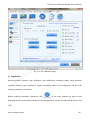
3.3 Partition calibration
H
C
R
A
O
C
.,
D
T
L
TE
T
S
A
V
N
A
O
N
Fig. 3-25 Partition calibration Flow Diagram
'
I
X
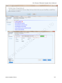
Partition calibration is the process of realizing screen calibration when calibration parameter
settings are finished.
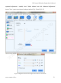
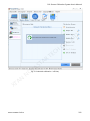
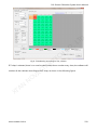
3.3.1 Partitions
"Partitions" here is regarded as a verb-divide. Consider the constraint of the size of camera lens,
the screen need to divide into several proper subareas to calibrate.
www.novastar-led.cn
36
Full-Screen Calibration System User's Manual
3.3.1.1
Normal Partition
H
C
R
A
O
C
.,
D
T
L
TE
T
S
A
V
N
A
'
I
X
www.novastar-led.cn
O
N
Fig. 3-26 Page Of Partitions
37
Full-Screen Calibration System User's Manual
H
C
R
A
O
C
.,
D
T
L
TE
T
S
A
V
O
N
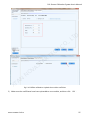
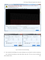
Fig. 3-27 Parameter Setting of Normal partitions
Due to the limitation of the camera's resolution, the screen needs to be divided into several
N
A
'
I
X
proper subareas to be calibrated.
Recommend users to adopt intelligent partition. Click
, thus the software will
automatically divide the display into serveral partitions of reasonable size;
click
to adopt customized partition.Single subarea rows and columns settings may
refer to the top of the recommended partition size, generally speaking, 224 x 150 is more
appropriate.
www.novastar-led.cn
38
Full-Screen Calibration System User's Manual
D
T
L
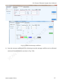
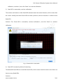
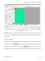
When finished, click "Create Partition", then you can see the result as shown in fig 3-28.
H
C
R
A
O
C
.,
TE
T
S
A
V
N
A
O
N
'
I
X
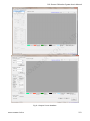
Fig. 3-28 Topography Graph And Screen Control Window
Topography Graph
It is composed of divided subareas, and number these subareas from left to right, from top to
www.novastar-led.cn
39
Full-Screen Calibration System User's Manual
bottom.
Screen Control
It is used to realize the control of screen color, brightness and division switch.
The right window can move together with the main window, and can shut down when
unnecessary. Click "Partition Topological Graph And Screen Control" on the right page, it will
popup.
D
T
L
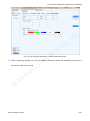
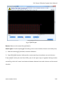
It is advised to check“Eliminate the boundaries of the Partitions” to eliminate differences among
partitions.
O
C
.,
If there is binding around the display, it is necessary to check “Exsit some leds obscured” and
input the columns and rows of borders and then click
TE
successful when see the fist rows or columns have on it .
R
A
H
C
to view the screen. The operation is
T
S
A
V
N
A
O
N
'
I
X
www.novastar-led.cn
40
Full-Screen Calibration System User's Manual
H
C
R
A
O
C
.,
D
T
L
TE
T
S
A
Fig. 3-29 Setting the number of rows and columns of borders
V
O
N
After division, click "Next", enter into "Connect to camera".
3.3.1.2
N
A
Large partition
'
I
X
Compared to normal partition, large partition features that the correction area is several times
larger than normal partition. For example, if the unit number is set as 5×5, the maximum
correction area is 224×5,150×5 when the camera adopts large partition. The current supporting
number of element is 10×10 in maximum; the correctable area is 2240×1500 in maximum.
If large partition calibration is adopted, full-screen calibration is no longer necessary.
www.novastar-led.cn
41
Full-Screen Calibration System User's Manual
H
C
R
A
N
A
TE
T
S
A
V
O
N
O
C
.,
D
T
L
Fig. 3-30 Large partition
'
I
X
www.novastar-led.cn
42
Full-Screen Calibration System User's Manual
H
C
R
A
O
C
.,
D
T
L
TE
T
S
A
V
O
N
Fig. 3-31 Parameter Setting of Large Partition Calibration
Click
'
I
X
N
A
, thus the software will calibrate the proper pixel size of a single partition
according to the display size and conduct auto-partition.
Click
to set the unit size when adopting customized partition.where columns and
rows collected by the camera cannot exceed the default value "224×150", and the partition size
(unit columns and rows ×columns and rows collected by the camera) is displayed at the bottom
of the interface. After setting is finished, click
www.novastar-led.cn
.
43
Full-Screen Calibration System User's Manual
Fig. 3-32 Custom size
O
C
.,
D
T
L
If there is binding around the display, it is necessary to check “Exsit some leds obscured” and
H
C
input the pixels of columns and rows of borders and then click
to view the screen. The
operation is successful when see the fist rows or columns have on it .
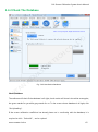
3.3.2 Connect To Camera
R
A
TE
T
S
A
V
O
N
When succeed in connecting to camera, the interface appears as fig 3-33 show. You can click help
documents on the left to obtain some camera operating skills and partition imaging techniques.
N
A
'
I
X
www.novastar-led.cn
44
Full-Screen Calibration System User's Manual
H
C
R
A
O
C
.,
D
T
L
TE
T
S
A
V
O
N
3.3.3 Camera Parameters
N
'A
I
X
Fig. 3-33 Connect To Camera
No matter manual mode or automatic mode is adopted, adjust the saturation till the result
reaches "Normal", and adjust the image size to "Proper",and during this process, make sure that
the camera faces to the partition.
Notice: If the image area is relatively small when the saturation is normal, the micro focus ring can
be adjusted to blur the image, After zooming the camera window. the image seen in camera
window is different from the actual image. The user can solve the problem by clicking the LED
light spot in the image prompted by magnifying glass to separate them.
www.novastar-led.cn
45
Full-Screen Calibration System User's Manual
H
C
R
A
O
C
.,
D
T
L
TE
T
S
A
V
Automatic Mode
N
A
O
N
Fig. 3-34 Camera Parameters
'
I
X
This mode is the default mode. Under this mode, users just need to click on "Auto All" button,
then the software will automatically analysis and adjust the saturation, finally achieve "normal". If
failed, please check the calibration environment and parameters, then try again.
The below dialog would be shown when clicking ‘Auto’ or ‘Auto All’ button. Please go to
LCT offline calibration interface according to the tips.
www.novastar-led.cn
46
Full-Screen Calibration System User's Manual
H
C
R
A
O
C
.,
D
T
L
TE
T
S
A
V
N
A
Manual Mode
O
N
Fig. 3-35 Set display parameters
'
I
X
Under this mode, users should adjust calibrate brightness, exposure time and aperture size. When
adjusting, give priority to "aperture", followed by "exposure", and finally "brightness".
Attention: The default brightness under large partition mode is 50, and the routine partition
is 30. Automatic analysis is advisable. Manual adjustment can be carried out if experienced.
Next step can be taken only if the analysis result is normal. Saturation between 60 and 100 is
normal,it is proper to adjust the image size to 50~150.
www.novastar-led.cn
47
Full-Screen Calibration System User's Manual
You can click
to view the image obtained after saturation adjustment, in order to help find
problems. When red, green, blue analyses are all completed, click "next" to enter into the page
"Partition calibration".
3.3.4 Partition Calibration
No matter manual mode or automatic mode is adopted, make sure the adjusting result of the
D
T
L
saturation to be normal, and during this process, make sure that the camera faces to the partition.
H
C
R
A
O
C
.,
TE
T
S
A
V
N
A
O
N
'
I
X
www.novastar-led.cn
48
Full-Screen Calibration System User's Manual
H
C
R
A
O
C
.,
D
T
L
TE
T
S
A
V
1) Preparation
N
A
O
N
Fig. 3-36 The Calibration Page
'
I
X
Normal partition supports gap calibration and coefficients uploading stably; Large partition
supports enabling gap calibration, system uploading stably and background off. And the
operating method is as follows:
Before enabling automatic calibration, click
at the main interface to pop out the
following window (the setting interface for the big partition), tick the corresponding option, click
"OK”.
www.novastar-led.cn
49
Full-Screen Calibration System User's Manual
Fig. 3-37 Normal settings for large partition
Enable gap calibration
H
C
O
C
.,
D
T
L
This is an option enabled when Normal partition calibration. Gap calibration is mainly used for
TE
small pixel pitch LED displays calibration, to solve the bright and dim line caused by cabinet
R
A
assembly. Note: bright and dim line must be inside Partitions.
T
S
A
Click “Normal setting” on the main menu to pop up the window below, and then check
“Enable gap calibration".
O
N
V
Coefficient uploading stably
N
A
Coefficient uploading stably means to upload calibration coefficient via serial cable, the speed is
'
I
X
slower but stable. Default calibration coefficient uploading route is via DVI cable, the speed is
faster. If there’s something wrong with DVI cable, serial cable can be used as alternative by
selecting coefficient uploading stably.
NovaPro support two mode of uploading, and the default is quickly uploading mode.
Enable Background off
Background removal is to remove background light, which is an option enabled when large
partition calibration. Generally, calibration is required only to be conducted under relatively dark
www.novastar-led.cn
50
Full-Screen Calibration System User's Manual
environment, but if background removal is enabled, calibration can be conducted even if the
environment is not dark enough.
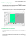
After "Enable background off" is selected, the interface shown in Fig. 3-36 is displayed. Users can
use the mouse to drag the four vertexes of the quadrangle to select the valid area to be calibrated.
The unwanted light around the screen to be calibrated is removed.
H
C
R
A
O
C
.,
D
T
L
TE
T
S
A
V
N
A
O
N
'
I
X
Fig. 3-38 Screen Area Determination
2)
Start Calibration
Automatic calibration Mode
www.novastar-led.cn
51
Full-Screen Calibration System User's Manual
Users just need to click "Start" button, the software can do the following things automatically:
analyze red, green and blue led, generate coefficients, upload coefficients, save to hardware and
to database. It will make calibration more convenient and efficient. Users may also manage this
flow according to their own requirements. Click "Customize" ,you can see fig. 3-38.
H
C
R
A
O
C
.,
D
T
L
TE
T
S
A
V
N
A
O
N
Fig. 3-39 Customize Window
Manual Calibration Mode
'
I
X
Users can separately operate every step of the calibration process.
For the partition is completed, users can test whether the calibration effect is good through
"pictures control" on the right side of this window. If bad, click "Calibration effect is not good?" on
the bottom left corner, check the help documents to help solve the problem. As shown in fig 3-39
www.novastar-led.cn
52
Full-Screen Calibration System User's Manual
H
C
Fig.3-40 Steps to Check Calibration Effects
O
C
.,
D
T
L
TE
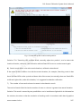
3) LED Identification Failure(This function is available only in the large partition mode)
R
A
Some emergency situations may happen during the calibration process, such as sudden
T
S
A
appearance of obstruction; user can click
When user clicks
picture.
N
A
to stop calibration under such condition.
V
to continue calibration, the camera will start shooting from the last
O
N
'
I
X
www.novastar-led.cn
53
Full-Screen Calibration System User's Manual
H
C
R
A
O
C
.,
D
T
L
TE
T
S
A
V
N
A
O
N
'
I
X
www.novastar-led.cn
54
Full-Screen Calibration System User's Manual
H
C
R
A
O
C
.,
D
T
L
TE
T
S
A
V
N
A
O
N
'
I
X
www.novastar-led.cn
55
Full-Screen Calibration System User's Manual
H
C
R
A
N
A
The user can click
'
I
X
TE
T
S
A
V
O
N
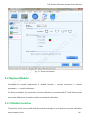
4) Change the target value
O
C
.,
D
T
L
Fig. 3-41 Pause Calibration
to change the target value in target calibration interface if the
calibration result is not satisfying after partition calibration. Brightness calibration, ordinary
chroma calibration and multiple bin chroma are all supported. Multiple bin chroma calibration
supports blue calibration which is mainly used for optimizing blue effect.
The user can input the value manually or modify the target value with auxiliary tools. Click
to view gamut distribution diagram after modification.
www.novastar-led.cn
56
Full-Screen Calibration System User's Manual
H
C
R
A
O
C
.,
D
T
L
TE
T
S
A
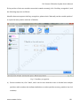
Fig. 3-42 Change the target value
V
O
N
Restore: Restore the calibration mode and target value to the value shown when the interface is
opened just.
N
A
'
I
X
Preview: View the effect on the display after the target value has been modified.
Enable correction: Check this option to view the effect of the latest correction coefficient on the
display.
Click
if the corrected target value is satisfying, and thus the system will prompts
“Whether apply the corrected target value into all partitions?” Check ‘Yes’, and thus the
system will recalculate the corrected correction coefficient of partition and load the new one. Click
“No”, and thus the target value will only be applied into the partition needs correction.
www.novastar-led.cn
57
Full-Screen Calibration System User's Manual
Click "Next Partition" to enter into the next partition calibration after partition calibration, and one
by one complete all partitions of the screen. When all finished, if still exist difference among these
partitions, then start "Full-screen Calibration" to eliminate it.
3.3.5 Partition Boundary
O
C
.,
D
T
L
When "partition" is conducted for the normal partition, if "Eliminate the boundaries of partitions"
H
C
is ticked and there are more than two partitions, it will enter the interface of “Partition Boundary"
after completion of calibration.
R
A
TE
T
S
A
V
N
A
O
N
'
I
X
www.novastar-led.cn
58
Full-Screen Calibration System User's Manual
H
C
R
A
O
C
.,
D
T
L
TE
T
S
A
V
O
N
Fig. 3-43 Partition Boundary
Eliminate the boundaries: To eliminate the boundaries of all present partitions.
N
A
'
I
X
Save To Hardware: Coefficients of partition calibration are saved to hardware, they will not be lost
in case of blackout.
Save to Database: Coefficients of partition calibration will be saved to database.
3.4 Modify screen
Full-screen calibration is used to eliminating the differences among partitions, improve uniformity
of the display screen. But users must notice that the precondition is the database created by
www.novastar-led.cn
59
Full-Screen Calibration System User's Manual
Partition calibration must be all saved.
H
C
R
A
O
C
.,
D
T
L
TE
T
S
A
V
N
A
'
I
X
www.novastar-led.cn
O
N
Fig. 3-44 Modify screen Calibration Flow Diagram
60
Full-Screen Calibration System User's Manual
3.4.1 Sub screen
H
C
R
A
O
C
.,
D
T
L
TE
T
S
A
V
N
A
O
N
Fig. 3-45 Sub screen
'
I
X
Sub screen
Divide display screen into several sub screens, it’s size is generally recommended 1*1, if the
screen is vertical strip or horizontal strip, you may set 2*1 or 1*2 to let camera obtain more clear
images.
www.novastar-led.cn
61
Full-Screen Calibration System User's Manual
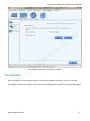
3.4.2 Check The Database
H
C
R
A
O
C
.,
D
T
L
TE
T
S
A
V
N
A
O
N
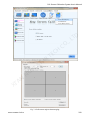
Fig. 3-46 New Revise Database
'
I
X
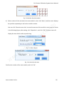
Check Database
The software will check if the database is all right, check results will show in the white rectangular,
the green stands for yes while gray stands for no. To the screen whose database is all right, click
"Re-Uploading".
If the screen calibration coefficient has already been not in conformity with the database, it is
required to click “Select All”, and re-upload.
www.novastar-led.cn
62
Full-Screen Calibration System User's Manual
Only whose database is all right can do full-screen calibration. After check, click "Next" to enter
into "Backup Database".
3.4.3 New Revise Database
H
C
R
A
O
C
.,
D
T
L
TE
T
S
A
V
N
A
'
I
X
O
N
Fig. 3-47 Backup Database
Backup Database
Full-screen calibration may update coefficients in the database, thus we need to backup database
to guarantee the original calibration coefficients unbroken. When you backup the database you'd
better indicate that it is created by Partition calibration to prevent confusion. The backup
database should be properly kept, when full-screen calibration failed affected by the
www.novastar-led.cn
63
Full-Screen Calibration System User's Manual
surroundings, you can use the backup database to do full-screen calibration again.
When completed, click "Next", enter into "Connect to camera".
3.4.4 Connect To Camera
The same as 3.3.2.
3.4.5 Camera Parameters
D
T
L
The same as 3.3.3, what should users notice is, when doing full-screen calibration, the camera
imaging doesn’t have to be clear, adjust it a little fuzzy will be better.
3.4.6 Full-screen Revise
H
C
R
A
O
C
.,
TE
T
S
A
V
N
A
O
N
'
I
X
Fig. 3-48 Page Of Full-screen Revise
www.novastar-led.cn
64
Full-Screen Calibration System User's Manual
Full-screen Revise
Be sure to aim the camera lens at the selected sub-screen, and then click “Start” to
automatically fulfill such functions as “Cancel sub-screen coefficients” and “Analyze Red,
green, blue LED”. “Cancel sub-screen coefficients” is to cancel the coefficients that are not
saved, and “Analyze Red, green, blue LED” requires partition effect;
then the software will do the following things automatically: Control screen display colors,
D
T
L
manage camera gain pictures and analysis intelligently. And the corresponding process can be
seen on the right of the page.
O
C
.,
If the sub-screen effect is good, click “Upload sub-screen Coefs" to automatically fulfill such
H
C
functions as “Revsie Coefs”, “Upload Coefs” and “Save to Database”.
TE
Make calibration for the sub-screens one by one. After the calibration, please keep the calibration
R
A
database with due care; when calibration to all sub-screens is completed, click “screen
T
S
A
coefficients integrating and uploading” to upload the screen coefficients; if the full-screen
calibration effect is good, click “save full-screen coefficients” and “save to database”.
V
O
N
So far, that’s all for all calibrations.
Attention: please be sure to confirm the full-screen calibration effect before save to database,
N
A
'
I
X
or partition database shall be loaded to do full-screen calibration again.
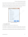
4 Modify dark or bright lines
The bright/dark line on the display can be adjusted by the function of modify dark or bright lines
when it is located at the splice between lamp panels or cabinets. The effect can be very
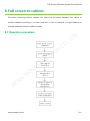
remarkable if the operation is proper. The operation process is as follow:
www.novastar-led.cn
65
Full-Screen Calibration System User's Manual
Initialization
Modify Lines
• Calibration
Mode
• Network
Setting
• Database
• Screen
Info
• Partition
• Camera
• Modify
Lines
4.1 Initialization
Correction mode choose "Modify dark or bright lines".
H
C
R
A
O
C
.,
D
T
L
TE
T
S
A
V
N
A
O
N
'
I
X
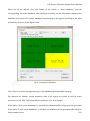
Fig. 4-1 Choose Calibration Mode
www.novastar-led.cn
66
Full-Screen Calibration System User's Manual
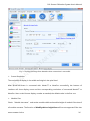
4.1.1 Network Settings
Input the IP and port (The port is set to 5200 ) of NovaPro or NovaCLB-Screen, then click "Connect"
button.After NovaCLB-Screen is connected with NovaLCT or NovaPro successfully, the bottom of
interface will show display count and the corresponding resolution of connected NovaLCT or
NovaPro. User can View the number of pixels of display screen by serial number.( Detailed network
settings, please refer to 3.2.2 Network settings)
If connection is failed, users could click
.
H
C
R
A
O
C
.,
D
T
L
TE
T
S
A
V
N
A
O
N
'
I
X
Fig. 4-2 Network Setting for Modify dark or bright lines
www.novastar-led.cn
67
Full-Screen Calibration System User's Manual
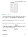
4.1.2 Database
To Create a new database; and the database is used for saving information of calibration
coefficient, calibration time, screen size, etc. it shall be kept properly.
Software default check the option "backup database", To enable the backup database can
effectively prevent database files were damage when abnormal shutdown or the computer
suddenly power off .
H
C
R
A
O
C
.,
D
T
L
TE
T
S
A
V
N
A
O
N
'
I
X
Fig. 4-3 Database setting for Modify dark or bright lines
Calibration Pictures
Click
to set the position where the collected images are saved during calibration.
www.novastar-led.cn
68
Full-Screen Calibration System User's Manual
For example, check “Save all subareas' pictures” to save the images in all partitions; un-checking
the option will only save the images in current partition in default setting.
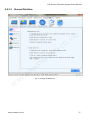
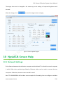
4.1.3 Calibration Information
The operation process varies with the calibration of display and can be divided into without
calibration, Screen calibration and Cabinet calibration. The user need to load database and pay
attention to the following items in the latter two situations:
1)
or higher version; moreover, the size of module must be identical.
2)
D
T
L
Screen Calibration, The full-screen calibration must be conducted with NovaCLB-Screen V4.0
O
C
.,
Cabinet calibration, the cabinet database must be converted to full-screen database at first.
H
C
R
A
TE
T
S
A
V
N
A
O
N
'
I
X
Fig. 4-4 Screen Info for Modify dark or bright lines
www.novastar-led.cn
69
Full-Screen Calibration System User's Manual
Dark or Bright lines Information
Select the position of bright/dark line among two types: between cabinets or between
modules (it is located between cabinets generally).
Fill in the number of columns and rows of each module.
Click
after setting to enter the Modify lines.
4.2 Modify lines
.,
D
T
L
Start calibration for bright/dark line after completing calibration initialization. As the camera
O
C
resolution is limited, the display needs to be divided into multiple areas of reasonable size for
H
C
calibration.
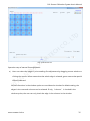
4.2.1 Partition
R
A
TE
Recommend users to adopt intelligent partition. Click
T
S
A
, and thus the software will
automatically divide the display into serveral partitions of reasonable size; users can also select
V
customized partition for calibration.
O
N
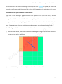
The size of Unit Block is the smallest one calculated by the system. The size of basic bright is 3*3,
N
A
that is, nine LEDs as shown below:
'
I
X
www.novastar-led.cn
70
Full-Screen Calibration System User's Manual
H
C
R
A
O
C
.,
D
T
L
TE
T
S
A
V
Fig. 4-5 Bright/dark line modification-partition
4.2.2 Camera
N
A
O
N
'
I
X
When succeed in connecting to camera, the interface appears as follows. You can click help
documents on the left to obtain some camera operating skills and partition imaging techniques.
www.novastar-led.cn
71
Full-Screen Calibration System User's Manual
H
C
R
A
O
C
.,
D
T
L
TE
T
S
A
V
N
A
O
N
Fig. 4-6 Connect to Camera
'
I
X
www.novastar-led.cn
72
Full-Screen Calibration System User's Manual
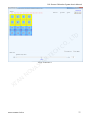
4.2.3 Modify Lines
H
C
R
A
O
C
.,
D
T
L
TE
T
S
A
V
N
A
O
N
Fig. 4-7 Modify Lines
'
I
X
1) Preparation
Before starting automatic Modify, click
at the main interface to pop out the following
window (the setting interface for the big partition), tick the corresponding option, click "OK”.
www.novastar-led.cn
73
Full-Screen Calibration System User's Manual
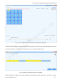
Fig. 4-8 Common Settings
Enable Background off
O
C
.,
D
T
L
Background removal is to remove background light, calibration is required only to be conducted
H
C
under relatively dark environment, but if background removal is enabled, calibration can be
conducted even if the environment is not dark enough.
R
A
2) Automatic Modify
TE
T
S
A
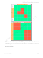
If "Enable background off" is selected, the interface shown in Fig.4-9 will be displayed when start
modify. Users can use the mouse to drag the four vertexes of the quadrangle to select the valid
V
O
N
area to be calibrated. The unwanted light around the screen to be calibrated is removed.
N
A
'
I
X
www.novastar-led.cn
74
Full-Screen Calibration System User's Manual
H
C
R
A
O
C
.,
D
T
L
TE
T
S
A
V
N
A
'
I
X
O
N
Fig. 4-9 Confirm area of display screen
3) Manual fine adjustment
The user can conduct manual trim if the modification result is not satisfying after
auto-modification.
Click
www.novastar-led.cn
to enter the fine Manual Trim interface of system as shown below:
75
Full-Screen Calibration System User's Manual
H
C
R
A
O
C
.,
D
T
L
TE
T
S
A
Fig. 4-10 Manual trim
Operation step of manual fine adjustment:
a)
V
O
N
Users can select the edge or point needing fine adjustment by dragging mouse window or
clicking the mouse. Yellow means that the whole edge is selected; green means that partial
N
A
'
I
X
LEDs are selected.
As both directions in the window option are considered as checked in default setting, the
edges in the rows and columns can be selected. If only “columns” is checked in the
window option, the user can only check the edge in the columns in the window.
www.novastar-led.cn
76
Full-Screen Calibration System User's Manual
H
C
R
A
O
C
.,
D
T
L
TE
T
S
A
Fig. 4-11 Window-1
V
N
A
O
N
'
I
X
www.novastar-led.cn
77
Full-Screen Calibration System User's Manual
H
C
R
A
O
C
.,
D
T
L
TE
T
S
A
Fig. 4-12 Window-2
The edge needing trimming can be selected with a single click of the mouse.
V
N
A
O
N
'
I
X
www.novastar-led.cn
78
Full-Screen Calibration System User's Manual
H
C
R
A
O
C
.,
D
T
L
TE
T
S
A
Fig. 4-13 Clicking the mouse to select the edge to be adjusted
Double-click the edge to pop up the following screen, you can click or select the light spot to be
V
O
N
trimmed. Hold Ctrl or shift key to click the mouse to select multiple spots.
N
A
'
I
X
Fig. 4-14 Select the light spots to be trimmed
After selecting the light spots, green indicates the light spots that have been selected, as shown
www.novastar-led.cn
79
Full-Screen Calibration System User's Manual
below.
H
C
R
A
O
C
.,
D
T
L
TE
T
S
A
Fig. 4-15 After selecting the light spots
V
O
N
Lock Selected: Lock the selected edge or spot.
Show number: When checked, number will be displayed on the screen.
b)
N
A
'
I
X
Drag the lever to fine adjust the coefficient. When checking “Enable modify effect”, it
indicates that trimming is conducted based on the previous correction; when not checking,
it indicates that trimming is conducted based on automatic correction.
c)
If the Modify effect is satisfactory, click
hardware. And then click
to save the coefficient to
to save the correction coefficient to
database.
www.novastar-led.cn
80
Full-Screen Calibration System User's Manual
5 Module Calibration
There are two modes for the replaced module, one is off-line mode, while another is connecting
with Control system (LCT or Pro)LCT for online calibration.
It is required to read the average calibration coefficient of the area to be calibrated when
conducting calibration to the module under off-line mode, and this coefficient shall be acquired
D
T
L
from LCT; after completion of module calibration, the calibration coefficient will be uploaded to
the screen through LCT.
O
C
.,
The calibration procedure of the off-line mode is basically the same as connecting to LCT mode,
H
C
which shall be stated together below, and the difference of part of the interface shall be paid
attention to.
R
A
NovaPro does not support offline mode.
TE
T
S
A
5.1 Initialization
V
Start the software, directly enter the calibration mode sub-interface of calibration initialization,
O
N
Choose "New module" of calibration mode, and click "Next", and enter the network setting
interface.
N
A
'
I
X
www.novastar-led.cn
81
Full-Screen Calibration System User's Manual
H
C
R
A
O
C
.,
D
T
L
TE
T
S
A
V
O
N
Fig. 5-1 Choose Calibration mode
5.1.1 Network setting
1)
N
A
'
I
X
Connect to Control system (LCT or Pro) for online calibration
Open the page frame of screen calibration on NovaLCT, then conduct network setting on
NovaCLB-Screen, where the IP and port are the same with Control system (NovalLCT or NovaPro),
and after completing, click "Connect".
After connecting successfully, NovaCLB-Screen automatically acquires the screen number and
pixels, and the number of the screen to be calibrated shall be selected.
www.novastar-led.cn
82
Full-Screen Calibration System User's Manual
H
C
R
A
O
C
.,
D
T
L
TE
T
S
A
V
N
A
O
N
'
I
X
Fig. 5-2 Network setting(on-line mode)
2)
Off-line mode
Correction process of Off-line mode is basically same with the mode of connection to LCT, pay
attention to the difference of the interface
Tick "Off-line mode", and click "Next".
www.novastar-led.cn
83
Full-Screen Calibration System User's Manual
H
C
R
A
O
C
.,
D
T
L
TE
T
S
A
V
O
N
Fig. 5-3 Network setting(off-line mode)
5.1.2 Database
N
A
'
I
X
New database or the existing database can be used, and the database is for saving the calibration
coefficient of the screen.
www.novastar-led.cn
84
Full-Screen Calibration System User's Manual
H
C
R
A
TE
T
S
A
V
O
5.1.3 Screen Info N
N
'A
I
X
O
C
.,
D
T
L
Fig. 5-4 Database
Fill the screen information based on actual situation, refer to 3.2.4 Screen Information in the
Chapter of full-screen calibration for details. Click "Next" after completion to enter the subpage of
"Module position" in "Module replacement".
www.novastar-led.cn
85
Full-Screen Calibration System User's Manual
H
C
R
A
O
C
.,
D
T
L
TE
T
S
A
V
O
N
5.2 Replace Module
N
'A
I
X
Fig. 5-5 Screen information
Procedures for module replacement is: module Location → camera connection → camera
parameters → module calibration.
For these procedures, the procedures of online calibration connected with LCT and off-line mode
have some differences in module position and module calibration.
5.2.1 Module location
The position of the new module shall be located accurately so as to perform accurate calibration
www.novastar-led.cn
86
Full-Screen Calibration System User's Manual
for the new module.
5.2.1.1
1)
Online calibration(Connect to LCT or Pro)
Manual setting
If the calibration personnel knows clearly about the coordinate position of the new module,
manual setting can be used to quickly set the coordinate and the module size, and click "Next" to
connect to the camera.
H
C
R
A
O
C
.,
D
T
L
TE
T
S
A
V
N
A
O
N
'
I
X
Fig. 5-6 Manually set the module position
2)
Auxiliary recognition
www.novastar-led.cn
87
Full-Screen Calibration System User's Manual
If the position of the new module cannot be located accurately, click "Auxiliary recognition"; and
the following steps are as follows:
NovaPro does not support Auxiliary recognition, please check "Manually set the module position"
to input the start position and size of Module.
H
C
R
A
O
C
.,
D
T
L
TE
T
S
A
V
N
A
O
N
'
I
X
Fig. 5-7 Auxiliary recognition
a)
Set the module size, click "Next", and it can be seen that the screen is divided into multiple
partitions with numbers (the software defaults to conduct partition as every partition has 4×4
modules).
www.novastar-led.cn
88
Full-Screen Calibration System User's Manual
Fig. 5-8 Module Size information
b)
Select number of the area where the new module is, then click "Next", and the screen displays
the partition separately as well as the module number.
D
T
L
User can click "Reset the area size" to reset the amount of the module in every area, as shown
O
C
.,
in the following figure; after setting, click "Reposition", and click "OK", and the screen will
display the area division after repositioning.
R
A
N
A
'
I
X
TE
T
S
A
V
O
N
H
C
Fig. 5-9 Select Region
Fig. 5-10 Re-divide the area
Confirm the number of the new module, and click "OK".
www.novastar-led.cn
89
Full-Screen Calibration System User's Manual
Fig. 5-11 Confirm Module location
5.2.1.2
Offline Calibration
D
T
L
Set pixel columns and rows of the screen, starting coordinate of the new module, and module size.
Click "Next".
H
C
R
A
O
C
.,
TE
T
S
A
V
N
A
O
N
'
I
X
Fig. 5-12 Module location(off-line)
www.novastar-led.cn
90
Full-Screen Calibration System User's Manual
5.2.2 Connect to Camera
During calibration, the camera must be connected to the calibration computer normally, kept as
aligning to partition and can photograph normally. If the camera is connected successfully, the
state of the camera is shown as follows, click "Next" to enter camera setting.
H
C
R
A
O
C
.,
D
T
L
TE
T
S
A
V
N
A
O
N
'
I
X
Fig. 5-13 Connect to Camera
5.2.3 Camera Parameters
No matter manual or automatic adjustment is used, adjust the saturation of the camera to be
normal, refer to 3.3.3 Camera parameters.
After completing setting, click "Next".
www.novastar-led.cn
91
Full-Screen Calibration System User's Manual
H
C
R
A
O
C
.,
D
T
L
TE
T
S
A
V
N
A
O
N
Fig. 5-14 Camera Parameter Settings
'
I
X
5.2.4 Module calibration
5.2.4.1
Online calibration (Connect to LCT or Pro)
The software defaults to tick "Automatic mode" and click "Enable automatic calibration", and the
software will finish the calibration to the module automatically.
User can cancel ticking "Automatic mode", and manually complete the module calibration
according to the calibration procedures on the right.
www.novastar-led.cn
92
Full-Screen Calibration System User's Manual
H
C
R
A
O
C
.,
D
T
L
TE
T
S
A
V
O
N
Fig. 5-15 Module calibration (online calibration)
5.2.4.2
N
A
Off-line mode
'
I
X
When you start calibration under the offline mode, some dialog would be shown. Please read the
tips on them carefully, and follow the tips to do certain operation, or the offline calibration cannot
finish successfully.
1)
Upload the module database to the new module
www.novastar-led.cn
93
Full-Screen Calibration System User's Manual
H
C
R
A
O
C
.,
D
T
L
TE
T
S
A
V
N
A
O
N
'
I
X
www.novastar-led.cn
94
Full-Screen Calibration System User's Manual
H
C
R
A
O
C
.,
D
T
L
TE
T
S
A
V
N
A
'
I
X
2)
O
N
Fig.5-16 Offline calibration-Upload the module coefficient
Make sure the coefficients have been uploaded to new module, and then click ‘OK’.
www.novastar-led.cn
95
Full-Screen Calibration System User's Manual
Fig.5-17 Make sure the coefficients in the database
3)
D
T
L
Get the average coefficient of calibration area on offline calibration interface of LCT and input
them.
O
C
.,
Respectively fill the coordinate, width and height (X, Y, W and H) of the new module area and the
H
C
collecting area of the Fig. 5-18 into the display area of Fig. 5-19, and then click "Get average
TE
coefficient" to get the average coefficients of the new module area and the area to be collected.
R
A
T
S
A
V
N
A
O
N
'
I
X
Fig.5-18 Average calibration coefficient of the area
www.novastar-led.cn
96
Full-Screen Calibration System User's Manual
H
C
R
A
O
C
.,
D
T
L
TE
T
S
A
Fig.5-19 Offline-Get Average coefficient
4)
V
Input the average coefficient of the collecting area at the average coefficient to be calibrated
O
N
window of NovaCLB-Screen (as shown in Fig. 5-18).
N
A
'
I
X
www.novastar-led.cn
97
Full-Screen Calibration System User's Manual
H
C
Fig.5-20 Input average calibration coefficient
5)
O
C
.,
D
T
L
TE
Check if the brightness calibration is enabled on the offline calibration interface of LCT, if it is
R
A
not, please enable it.
T
S
A
V
N
A
O
N
'
I
X
www.novastar-led.cn
98
Full-Screen Calibration System User's Manual
H
C
R
A
O
C
.,
D
T
L
TE
Fig.5-21 Enable brightness calibration
6)
T
S
A
Set display parameters for offline calibration on NovaLCT.
V
N
A
O
N
'
I
X
www.novastar-led.cn
99
Full-Screen Calibration System User's Manual
H
C
O
C
.,
D
T
L
TE
Fig. 5-22 Set display parameters in offline calibrationmode
7)
R
A
After completing setting, click "OK" to enable calibration, where the calibration procedure is
T
S
A
the same as the online mode.
V
N
A
O
N
'
I
X
www.novastar-led.cn
100
Full-Screen Calibration System User's Manual
H
C
R
A
O
C
.,
D
T
L
TE
T
S
A
V
O
N
Fig. 5-23 Module calibration(off-line)
N
A
'
I
X
www.novastar-led.cn
101
Full-Screen Calibration System User's Manual
6 Calibration
interruption
(Searching
LED
position failed)
No matter full-screen calibration or module calibration, after the calibration is enabled, various of
problems at the site may cause led position failed leading to calibration interruption, such as
screen binding, Dead LED or interference light. Generally, artificial location is adopted to help
D
T
L
solve these problems, and this section will introduce solutions for several common situation.
1) Normal binding
O
C
.,
Normal binding means that the whole columns or rows at the edge of the screen is wrapped
H
C
regularly, and the error of search appears as not enough detected columns and rows, as shown in
the following figure:
R
A
Solution:
TE
T
S
A
a)
Tick "Binding existed, need detection", and click "Next".
b)
The software detects four sides of the screen respectively, and the software defaults "Auto
V
O
N
switch"; user needs to pay attention to the state of the software (namely at which row or
N
A
column) while observing the lights lighting up at which stage of the screen, then record which
'
I
X
state so as to select state at the "result" and click "Next".
c)
After the four sides of the screen are detected, the software continues for calibration.
www.novastar-led.cn
102
Full-Screen Calibration System User's Manual
H
C
R
A
O
C
.,
D
T
L
TE
T
S
A
V
N
A
O
N
'
I
X
Fig. 6-1 Solution for Normal binding
2)
User considers the binding to be normal, calibration can be forced to continue sometimes,
user considers the binding to have little effect, then ticks "The error does not effect the
www.novastar-led.cn
103
Full-Screen Calibration System User's Manual
calibration, continue", then click "Next" to continue calibration.
3)
Dead LED is reasonable, continue calibration
The number and location of the Dead LED detected match the actual situation, which means that
the screen actually has these Dead LEDs at these positions, and this situation is called normal
Dead LED.
Solution: Tick "Dead LED is reasonable, continue calibration", and click "Next" to continue
calibration.
H
C
R
A
O
C
.,
D
T
L
TE
T
S
A
V
N
A
O
N
'
I
X
Fig. 6-2 Dead LED is reasonable
4)
Dead LED increased by failure of searching
The detected Dead LEDs are most fake Dead LEDs, which means that the actual screen does not
have so many Dead LEDs.
Solution:
www.novastar-led.cn
104
Full-Screen Calibration System User's Manual
a)
Tick "There does not exist so many Dead LED because of the LED searching failure ", and click
"Next";
H
C
R
A
O
C
.,
D
T
L
TE
T
S
A
V
Fig. 6-3 Death light rate is more than the normal range
b)
O
N
Adjust the first wrong LED point on the searching direction to right position, then click "search
again".
N
A
'
I
X
www.novastar-led.cn
105
Full-Screen Calibration System User's Manual
H
C
R
A
O
C
.,
D
T
L
TE
Fig. 6-4 Search Again
T
S
A
Restore: Restore to the state of the last search;
V
Search again: Conduct search again according to the current location direction and initial point;
O
N
c)
After the searching is successful, continue calibration.
5)
Dead LED at the location initial position causes searching inconsistent rows and columns
N
A
'
I
X
If the location initial point has Dead LEDs, part of the lights may be bypassed during location
monitoring, which will cause inconsistence between detected rows and columns and the actual
situation.
www.novastar-led.cn
106
Full-Screen Calibration System User's Manual
H
C
R
A
O
C
.,
D
T
L
TE
T
S
A
Fig. 6-5 Dead LED at the location initial position
Solution: Tick "Searching LED position failed, manually adjust the position", and re-select the
V
O
N
location direction, switch to a start direction without Dead LED so as to conduct search again.
6) Search result differs a lot with actual situations, calibration abandoned
N
A
'
I
X
If the result of search differs a lot with the actual situation, for example, Searching result is that
there are Dead LEDs at the up side and down side of the screen, but actually, there are Dead LEDs
at left and right sides, under this situation, it is suggested to abandon calibration.
7)
The number of rows and columns increases in the detection result
The result of search failed is that the number of rows or columns is greater than actual situation.
Solution: This result is caused by two possibilities: one is interference light which is eliminated as
the solution; the other is that the resolution of sending card is inconsistent with that of graphics
www.novastar-led.cn
107
Full-Screen Calibration System User's Manual
card, then the resolution of the sending card shall be set on LCT.
7 Full Screen Data Merging
Spot calibration often encounters such situation: a large screen is applied with multiple sending
cards for loading, and a video processor and a video stitching device are used between the
graphics card and the sending card to connect the frames; at this moment, the display and the
D
T
L
large screen are not in point-to-point display, and during calibration, the video process equipment
.,
needs to be skipped, and the large screen shall be divided into multiple split screen for respective
O
C
calibration; and after calibration, unsmooth transition may appear at the adjacent area of the split
H
C
screens, which is commonly known as layering. The full screen date merging tool is for solving this
problem.
R
A
TE
At the main interface of the software, click "Tools" → "Full screen data merging"; after opening
T
S
A
the tool, assume that the full screen has been divided into four regions for calibration, set 2 rows
and 2 columns of split screen.
N
A
O
N
V
'
I
X
www.novastar-led.cn
108
Full-Screen Calibration System User's Manual
H
C
R
A
O
C
.,
D
T
L
TE
T
S
A
V
N
A
O
N
'
I
X
Fig. 7-1 Full screen region data merging
www.novastar-led.cn
109
Full-Screen Calibration System User's Manual
Select one of the regions, click right button of the mouse → "Select database", load the
corresponding full screen database; after loading successfully, see the information related to the
database; and load the full screen database corresponding to all regions according to the same
procedures, as shown in the figure below.
H
C
R
A
O
C
.,
D
T
L
TE
T
S
A
V
N
A
'
I
X
O
N
Fig. 5-2 Loading the database
Click "Select" to set the storage directory for the database generated after merging.
Pay attention to whether current resolution ratio of all regions are match to the full screen
resolution or not; after confirming they are matched, click "Area merger".
If the option "Split-screen databases" is checked, four databases after merging will be generated;
if the option "Entire-screen databases" is checked, one database will be generated after merging.
www.novastar-led.cn
110
Full-Screen Calibration System User's Manual
8 Full screen to cabinet
Full-screen converting cabinet software can switch the full-screen database into cabinet or
module database according to a certain resolution. It can be switched to single database or
multiple databases based on different needs.
8.1 Operation procedure
H
C
R
A
O
C
.,
D
T
L
TE
T
S
A
V
N
A
O
N
'
I
X
www.novastar-led.cn
111
Full-Screen Calibration System User's Manual
8.2 Operation instruction
This chapter will illustrate operation steps of all procedures for users in detail.
8.2.1 Import database
H
C
R
A
O
C
.,
D
T
L
TE
T
S
A
V
N
A
O
N
'
I
X
www.novastar-led.cn
112
Full-Screen Calibration System User's Manual
H
C
R
A
O
C
.,
D
T
L
TE
T
S
A
V
N
A
O
N
'
I
X
Fig. 8-1 Import Screen database
www.novastar-led.cn
113
Full-Screen Calibration System User's Manual
8.2.2 Draw topological graph
Set the number of rows and columns of the cabinet, and then click
to generate a
topological graph in the right window of the software.
Note that the sum of the resolution of all rows and all columns of the cabinet shall be equal to the
resolution of the screen; therefore, under the premise that resolution of each cabinet is known,
number of rows and columns of the cabinet shall be calculated accurately.
H
C
R
A
O
C
.,
D
T
L
TE
T
S
A
V
N
A
'
I
X
O
N
Fig. 8-2 Draw topological
8.2.3 Set resolution of each cabinet
First, select the cabinet which will be set in certain resolution, then set the resolution, and click
.
The cabinets can have different resolution; however, for cabinets on the same row, rows of the
resolution shall be the same, and for cabinets on the same column, columns of the resolution shall
www.novastar-led.cn
114
Full-Screen Calibration System User's Manual
be the same; when the resolution setting is irrational, the color
will appear; the sum of the
resolution of all rows and all columns of the cabinet shall be equal to the resolution of the screen.
Instruction of the right-click menu of the cabinet:
Right-click on the topological graph will show two options in the right-click menu, "Partition
averagely" and "Clear settings". " Partition averagely": partition the resolution of the display
averagely on the drawn topological graph of the cabinet with resolution of each cabinet being the
D
T
L
same. "Clear settings": clear the resolution and cabinet name set on the topological graph.
The following methods can be used to select the cabinet:
a)
O
C
.,
Select the first cabinet, hold down the mouse and drag according to the direction of arrow in
H
C
the figure; the result is as follows:
R
A
TE
T
S
A
V
N
A
O
N
'
I
X
b)
Press the "Ctrl" key to conduct multiple selections; the result is as follows:
www.novastar-led.cn
115
Full-Screen Calibration System User's Manual
H
C
R
A
O
C
.,
D
T
L
TE
T
S
A
V
N
A
c)
O
N
'
I
X
Select one cabinet as the start, press the "Shift" key, and then select another cabinet as the
end; in this way, the rectangular area from the start cabinet to the end cabinet can be selected;
the result is as follows:
www.novastar-led.cn
116
Full-Screen Calibration System User's Manual
H
C
R
A
O
C
.,
D
T
L
TE
T
S
A
V
N
A
O
N
'
I
X
d)
Press "Ctrl+A" to select all cabinets; the result is as follows:
www.novastar-led.cn
117
Full-Screen Calibration System User's Manual
TE
The topological graph with set resolution is shown as follows:
R
A
H
C
O
C
.,
D
T
L
T
S
A
V
N
A
O
N
'
I
X
Fig. 8-3 Resolution setting
www.novastar-led.cn
118
Full-Screen Calibration System User's Manual
8.2.4 Number the cabinet
Numbering can be automatic or manual.
1)
Automatic numbering
Check "Auto", select numbering method, row/column number, number of digit, and set fixed digit
and initial value, and then click
.
H
C
R
A
O
C
.,
D
T
L
TE
T
S
A
V
Fig. 8-4 Select Numbering mode
O
N
Numbering method: column direction, row direction, Z-shaped.
N
A
Row/column number: When selecting column direction and row direction, it needs to select the
'
I
X
first row/column, the second row/column, the third row/column,……, the nth row/column, and
number them respectively; the following figure is the topological graph after being numbered.
www.novastar-led.cn
119
Full-Screen Calibration System User's Manual
H
C
O
C
.,
D
T
L
TE
Fig. 8-5 Numbering according to row, column
R
A
If Z-shap is selected, there is no need to select row/column number every time; the software will
T
S
A
number all the cabinets according to the Z-shap, as shown in the following figure:
V
N
A
O
N
'
I
X
www.novastar-led.cn
120
Full-Screen Calibration System User's Manual
H
C
R
A
O
C
.,
D
T
L
TE
Fig. 8-6 Z-shap Numbering
T
S
A
Fixed digit: fixed numbering character at the beginning of the number which can be set by the
V
user; it can be any character, for example, A-, B-, number-, etc.
O
N
Number of digit: number of digit for the number, 1-4 digits; as shown in the following figure, the
N
A
numbers of the first and second column have 2 digits; the number of the second column has one
'
I
X
digit; the fourth column has 4 digits; and the fifth column has 3 digits.
www.novastar-led.cn
121
Full-Screen Calibration System User's Manual
H
C
R
A
O
C
.,
D
T
L
TE
Fig. 8-7 Set the number of digit
T
S
A
Initial value: it means the initial value of the digit position in a single numbering process; for
V
example, A-01 to A-08 can be used for the first column, and the initial value of the second column
can be set as 9.
2)
N
A
Manual numbering
'
I
X
O
N
Each time, number shall be entered manually; for example, enter the number A01, select the first
cabinet, and then click
to finish the numbering of the first cabinet; then enter
A02, select the second cabinet, and then click
to finish the numbering of the
second cabinet; and the following can be done in a similar way to finish numbering of all cabinets.
www.novastar-led.cn
122
Full-Screen Calibration System User's Manual
Fig. 8-8 Select Manual numbering mode
8.2.5 Set target database
H
C
O
C
.,
D
T
L
TE
There can be single target database or multiple target databases. For single target database, all
R
A
cabinets or modules will be saved to one database and one database will be generated. For
T
S
A
multiple target databases, single cabinet or module will be saved as one database, and multiple
databases will be generated which are named after the number of each cabinet or module.
8.2.6 File path
N
A
O
N
V
In the case of saving as one single database, there are two situations. One is to save the cabinet
'
I
X
data to the existing database which requires clicking
to open the existing database.
The other is to save the cabinet data to a new database, which requires clicking
to
create a new database on some path of the computer.
In the case of saving as multiple databases, click
to select the saving path of the
cabinet database.
www.novastar-led.cn
123
Full-Screen Calibration System User's Manual
8.2.7 Switch
After completion of settings of all the options above, click
.
H
C
R
A
O
C
.,
D
T
L
TE
T
S
A
V
O
N Targets
9 Screen Update
N
'A
I
X
Fig. 8-9 Converting completed
If the brightness and chroma of the full screen is not satisfactory after the calibration is completed,
the full-screen target value can be modified through this function.
The operation is as follows:
www.novastar-led.cn
124
Full-Screen Calibration System User's Manual
H
C
R
A
O
C
.,
D
T
L
TE
T
S
A
Fig. 9-1 Screen update targets
V
Click the first
O
N
to import the original database, and click the second
to
set the route of the target database.
N
A
'
I
X
The modification method of the target value is the same the setting of “Expected brightness and
chroma”.
After the modification is completed, click
Click the first
to save and apply the target value.
, It can be individually loaded into the database or project; after being
individually loaded into the database, the colorimetric correction mode cannot be changed; after
being loaded into project, the correction modes can be changed freely. then click the second
to set the path of the target database.
www.novastar-led.cn
125
Full-Screen Calibration System User's Manual
The target value can be changed in the same way as the setting of "expected brightness and
chroma".
After the change, click
to save the target value and apply.
H
C
R
A
O
C
.,
D
T
L
TE
T
S
A
V
N
A
O
N
Fig.9-2 Screen Update Targets
10 NovaCLB-Screen Help
'
I
X
10.1 Network Settings
If the distance between the calibration computer and the NovaLCT or NovaPro control computer
is within 100m when performing calibration, Ethernet cables can be used to connect the two
computers. Otherwise, wireless routers should be used.
Here TP-LINK WR941N will be taken as an example for illustrating how to configure a wireless
www.novastar-led.cn
126
Full-Screen Calibration System User's Manual
router for calibration application:
Fig. 10-1 The Wireless router TP-LINK WR941N
1)
Connect the wireless router with the control computer through the network cable
into the yellow interface.
H
C
Fig. 10-2 Ports for Connection
2)
O
C
.,
D
T
L
TE
Enable the wireless networking capabilities of calibration computer to connect to wireless
R
A
router.
T
S
A
Pay attention, whether use network cable or wireless router, you need to set the IP of the two
computers and the default IP of wireless when calibrate with NovaLCT, and you need to set the IP
V
O
N
of calibration computer,NovaPro , and the default IP of wireless when calibrate with NovaPro.
you need to set the IP of the two computers and the default IP of wireless router to be within the
N
A
'
I
X
network segment.
www.novastar-led.cn
127
Full-Screen Calibration System User's Manual
Fig. 10-3 IP Configurations
H
C
10.2 LCT Monitor Settings
R
A
O
C
.,
D
T
L
TE
Ensure that network is normal, then users need to open NovaLCT-Mars, and choose advanced
T
S
A
users, the pass word is 666, as shown in fig. 10-4
V
N
A
O
N
'
I
X
Fig. 10-4 LCT Main Interface
After loading by advanced user, NovaLCT-Mars toolbar will appear calibration options, click into
the calibration page.
www.novastar-led.cn
128
Full-Screen Calibration System User's Manual
Fig. 10-5 Calibration Page
O
C
.,
D
T
L
After getting into the calibration page, please check the network settings to make sure network
H
C
normal, then click "Reconnect". The message of "Listening succeed" shown in the following
TE
message window indicates that calibration service has been activated, if not, please check the
R
A
network.
T
S
A
V
N
A
'
I
X
O
N
Fig. 10-6 Enter into Calibration Mode
10.3 Principle of Brightness and Color Calibration
Generally speaking, it is recommended that users select brightness and color calibration mode,
they can obtain higher uniformity. For some customers demanding more colorful and brighter,
they can choose brightness calibration only.
Brightness calibration: Brightness calibration is to adjust the brightness of LED lights to improve
www.novastar-led.cn
129
Full-Screen Calibration System User's Manual
the brightness uniformity. In the brightness calibration, brightness of most lights will be properly
lowered. Fig.10-7 shows an example of brightness adjustment of green LED lights, in which there
are two brightness distribution curves corresponding to before and after calibration (adjustment)
respectively. Before calibration, the brightness values of green LED lights are scattered between
2400 – 3300 cd/m2, but after calibration those are concentrated almost at 2500 cd/m2,
representing high brightness uniformity.
H
C
R
A
O
C
.,
D
T
L
TE
T
S
A
Fig. 10-7 Brightness Values Distribution Before and After Calibration
Brightness and color calibration: Brightness and color calibration is based on the theory of RGB
V
O
N
color match. It adjusts the coordinates of LED lights in the RGB color coordinate system to reduce
the color diversity. As shown in Fig.10-8, the large triangle is the gamut of a LED display before
N
A
'
I
X
calibration , while the small one is the gamut of same LED display after calibration. The R, G and B
color coordinates of LED lights scatter in relative large areas when before corrected while those
after calibration are concentrated, which represents high color uniformity.
www.novastar-led.cn
130
Full-Screen Calibration System User's Manual
Fig. 10-8 Gamut of A LED Display Before and After Calibration
O
C
.,
D
T
L
Note that when performing the brightness and color calibration, proper coordinates for R, G and
H
C
B should be chosen in order to avoid color distortion.
10.4 Camera Operating Skills
R
A
TE
T
S
A
Camera Preparation:
Use a USB cable to connect the camera to the computer. Set the camera to "ON." Click "Connect
V
O
N
to camera." After "Connected" is displayed, users can automatically control the camera using the
software.
N
A
'
I
X
Set the mode dial
to "M" (manually) and lens focus
to "M" (manually). If
the lens supports the anti-shake function ("OS" on Sigma cameras), set
to "OFF."
Switchover between eyepiece framing and LCD framing: Enable "Live view shoot" in "MENU" of
the camera and press
to switch between eyepiece framing and LCD framing.
Tip: When LCD framing is enabled, users can press
www.novastar-led.cn
to switch among original size,
131
Full-Screen Calibration System User's Manual
five times the original size and ten times the original size for images.
Adjustment of the Camera Saturation:
Click "Analyze." The software automatically calculates the saturation. Adjust the aperture size,
D
T
L
time of exposure and calibration brightness value to enable the saturation to be normal. The
saturation value ranging from 60 to 100 is normal, and the area value ranging from 50 to 150 is fit.
O
C
.,
The adjustment principle is as follows: the adjustment must be conducted in the following order:
aperture size > time of exposure > calibration brightness value. Generally, the aperture value is
H
C
inversely proportional to the saturation, and the time of exposure and brightness are directly
TE
proportional to the saturation. After the red (R) saturation, green (G) saturation and blue (B)
R
A
saturation are normal, click "Confirm configuration."
T
S
A
V
N
A
O
N
'
I
X
www.novastar-led.cn
132
Full-Screen Calibration System User's Manual
H
C
R
A
O
C
.,
D
T
L
TE
T
S
A
V
O
N
10.5 Subarea Imaging Operating Skills
N
'A
I
X
Fig. 10-9 Camera Parameters Adjustment
Manage the camera aim at the subarea to be calibrated and adjust lens focus length, so that the
image of the subarea has a proper view.
Because of the outer part of the lens decreases in imaging quality, the direction of the camera
should be adjusted to ensure the subarea image is at the center part of the whole image. And the
size of the subarea image should be about 4/5 of the whole image size. That is to leave 1/10 of the
whole image at sides, as shown in Fig 10-10.
www.novastar-led.cn
133
Full-Screen Calibration System User's Manual
(a)Subarea Image Too Small
(b) Subarea Image Too Large
(c)Suitable Subarea Image Size
H
C
Fig. 10-10 Imaging of A Subarea
TE
Adjust focus length for clear image, as shown in Fig 10-11
R
A
O
C
.,
D
T
L
T
S
A
V
N
A
'
I
X
O
N
(a) Blur Image
(b) Clear Image
Fig. 10-11 Focus for Clear Image
For factory calibration, it is not recommended to use the maximum lens focus length . Because the
pixel size is less than the supported maximum subarea size, the suitable focus length is that makes
the cabinet view centre is at the center of the whole view.
10.6 Large partition operating technique
When selecting large partition calibration, the camera can calibrate maximum partition of
www.novastar-led.cn
134
Full-Screen Calibration System User's Manual
2240X1500.
The partition photographed at one time with the camera is equivalent to the number of columns
of single partition pixels dividing unit columns multiplying the number of rows of single partition
pixels dividing unit rows, due to camera limitation, the number of unit and single partition pixels
set shall better satisfy the following conditions:
The number of columns of single partition pixels dividing unit columns shall be less than 224;
D
T
L
The number of rows of single partition pixel dividing unit rows shall be less than 150;
10.7 Steps to Check Calibration Effects
H
C
O
C
.,
It may occur unsatisfactory calibration effects in some areas of screen after calibration, then
TE
troubleshoot according to calibration effect is needed. Before checking, users should know how
R
A
to check "Camera Image Collection".
Click magnifying glass icon
T
S
A
in Partition calibration page, then measurement image page
appears. First, observe the image resolution and integrity, second, observe whether all led points
V
O
N
have been selected. As shown in Fig.10-12:
N
A
'
I
X
www.novastar-led.cn
135
Full-Screen Calibration System User's Manual
H
C
Fig. 10-12 View of Collection Images
O
C
.,
D
T
L
TE
Screen fuzzy phenomenon1: there appears some bright or dark wirings in vertical
R
A
direction between subareas.
T
S
A
Analysis: Generally speaking, it is because of poor quality of imaging, users may check whether
LED image clear or not on "Camera Image Collection". Generally both Oversize resolution when
V
O
N
partition setting and not clear focus when the imaging may lead poor quality of imaging.
Screen fuzzy phenomenon2: there appears water ripples in subareas
N
A
'
I
X
Analysis: Generally speaking, it is because of inadequate sampling. Show red, green and blue
image on LED screen after calibration to find out undesirables color. Slightly adjust the focus or
re-focus, then repeat the calibration of the color, you can solve the problem.
Moreover, some scene reasons may also lead unsatisfactory, for example, outside light
interference, lens jitter by site windy and imaging fuzzy by rain and snow. In order to reach the
most ideal effect, engineers need to avoid these influences of external environment.
www.novastar-led.cn
136
Full-Screen Calibration System User's Manual
10.8 Water Ripple in Full-Screen Calibration
Full-screen calibration may appear full screen of a color rendering water ripple, blue share the
highest frequency. This is due to that the display resolution is too large, and the relative lack of
camera resolution leads the low sampling frequency. It is known as moiré patterns phenomenon
in optical imaging.
Try below resolutions to solve this problem, and then collect R/G/B again.
D
T
L
Change camera angle. Rotate camera lightly to change its angle to eliminate or reduce the
existing moiré patterns.
O
C
.,
Change camera position. Move camera up or down or left or right to reduce moiré patterns.
H
C
Change camera focusing. Too clear focus and details may cause moiré patterns, please adjust
TE
camera aperture to reduce camera focus Clarity, furthermore to reduce moiré patterns.
R
A
Change camera lens. Try different focus length to reduce or eliminate moiré patterns.
T
S
A
Try to divide the full screen into several parts to perform calibration when performing full screen
V
correction. The reduction of imaging points can help eliminate Moiré Effect.
N
A
O
N
'
I
X
www.novastar-led.cn
137
Full-Screen Calibration System User's Manual
11 Edition Statement
Edition
Issuing Date
Corresponded Software Version
User Manual of NovaCLB-Screen Full Screen System-V1.0
25/09/2012
First Release
User Manual of NovaCLB-Screen Full Screen System -V2.0
19/12/2012
NovaCLB-ScreenV1.9.0
User Manual of NovaCLB-Screen Full Screen System -V2.2
06/09/2013
NovaCLB-ScreenV2.0.0
User Manual of NovaCLB-Screen Full Screen System -V3.1.0
07/03/2014
NovaCLB-ScreenV3.1.0
User Manual of NovaCLB-Screen Full Screen System -V3.2.0
08/04/2014
NovaCLB-ScreenV3.2.0
User Manual of NovaCLB-Screen Full Screen System -V3.3.1
01/26/2015
NovaCLB-ScreenV3.3.1
User Manual of NovaCLB-Screen Full Screen System -V3.4.0
04/21/2015
NovaCLB-ScreenV3.4.0
User Manual of NovaCLB-Screen Full Screen System -V4.0.0
09/22/2015
NovaCLB-ScreenV4.0.0
R
A
H
C
O
C
.,
D
T
L
TE
T
S
A
V
N
A
O
N
'
I
X
www.novastar-led.cn
138