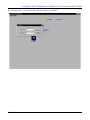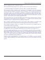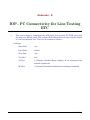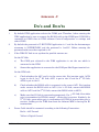
1
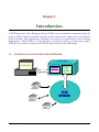
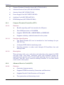
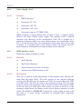
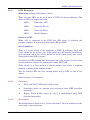
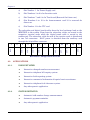
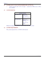
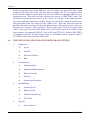
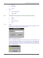
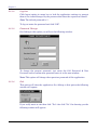
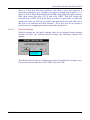
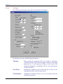
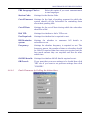
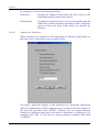
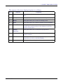
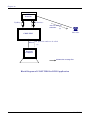
C-DOT IVRS
USER MANUAL
Section No. 410-027-0778
System
Practices
Draft 04, May 2003
C-DOT IVRS
USER MANUAL
© 2003, C-DOT
Printed in India
C-DOT IVRS
USER MANUAL
DRAFT 04
DECEMBER 2003
JYESTHA 2060
SERIES 000 : OVERVIEW
CSP SECTION NO. 410-027-0778
THIS C–DOT SYSTEM PRACTICE REFERS TO THE C–DOT INTERACTIVE VOICE RESPONSE
SYSTEM (ABBREVIATED AS C–DOT IVRS IN THE REST OF THIS PUBLICATION).
THE INFORMATION IN THIS SYSTEM PRACTICE IS FOR INFORMATION PURPOSES AND IS
SUBJECT TO CHANGE WITHOUT NOTICE.
A COMMENT FORM HAS BEEN INCLUDED AT THE END OF THIS PUBLICATION FOR
READER'S COMMENTS. IF THE FORM HAS BEEN USED, COMMENTS MAY BE ADDRESSED
TO THE DIRECTOR (SYSTEMS ), CENTRE FOR DEVELOPMENT OF TELEMATICS, 39, MAIN
PUSA ROAD, NEW DELHI - 110 005
© 2003 BY C–DOT, NEW DELHI.
Table of Contents
Chapter 1.
Introduction ..............................................................................................................................5
Chapter 2.
Hardware Description ..............................................................................................................7
Chapter 3.
Maintenance of IVRS Application .........................................................................................15
Chapter 4.
Interactive Changed Number Announcement System ........................................................36
Chapter 5.
Bill Enquiry System ...............................................................................................................43
Chapter 6.
Interactive Fault Clearance System .....................................................................................51
Chapter 7.
Interactive Commercial Information and Special Services Assistance ..............................54
Chapter 8.
Interactive Fault Reporting System......................................................................................62
Chapter 9.
Payment Reminder System ...................................................................................................66
Chapter 10.
Automatic Bulk Telephone Number Change Announcement System ................................75
Chapter 11.
Current Meter Reading System.............................................................................................84
Chapter 12.
Report Generation ..................................................................................................................86
Chapter 13.
Maintenance of IVRS Datamanager ...................................................................................105
Annexure - A
Alarms Generation for Fan Failure.....................................................................................124
Annexure - B
Procedure for Announcement Downloading .......................................................................125
Annexure - C
Interface with Commandir...................................................................................................127
Annexure - D
IVRS and TRA Interfacing Procedure.................................................................................128
Annexure - E
IOP - PC Connectivity for Line Testing ETC......................................................................130
Annexure - F
Do's and Don'ts .....................................................................................................................131
Annexure - G
Glossary.................................................................................................................................133
H:\HOME\IVRS\IVRSUSRM.DOC
April 26, 2004
Chapter 1.
Introduction
C-DOT Interactive Voice Response System (IVRS) can be seamlessly integrated with the
present Indian Telecom Network through normal twisted pair copper wire or E1 digital
trunk interface. The applications developed are based on requirements from Telecom
Department. C-DOT IVRS can cater 60 ports, of which 30 ports on twisted pair copper/
PCM (E1) and another 30 ports on PCM (E1) interface from Local Exchange.
1.1.
POSITION OF C-DOT IVRS IN THE NETWORK
C-DOT IVRS
COMPUTER
Resource
Hardware
Two-wire &
Digital
trunk
interface
PSTN
NETWORK
USER MANUAL
5
Chapter 1
1.2.
6
SALIENT FEATURES
•
Interactive Voice Response System.
•
Developed using C-DOT low cost hardware and software.
•
Caters upto 60 channels simultaneously.
•
Application developments and GUI for Man-machine interface is done on PC.
•
Serial port connectivity from PC to System Hardware.
•
Voice files can be downloaded from PC to the Hardware.
•
Application is independent of hardware.
•
Multiple applications are supported in a single system.
•
Supports both analog tip/ring and PCM (E1 interface).
•
Implemented using state-of-art DSP technology.
•
Supports global DTMF and Decadic detection.
•
Supports CAS signaling on E1 with MF-R2.
•
Redundancy of PCs supported.
•
Ergonomic table-top design of the Cabinet, with non-AC operation.
C-DOT IVRS
Chapter 2.
Hardware Description
2.1.
SYSTEM LEVEL SPECIFICATIONS
S.No.
FEATURES
SPECIFICATION
1
Capacity
Can cater upto 60 ports .
2
Exchange Side Interface
30 Subscriber lines (tip & ring) and or one E1 digital trunk
alternatively.
Supports two numbers of 2Mbps digital trunk (E1) over
shielded symmetrical twisted pair of 120 Ohms (G. 703).
3
Power
Power is derived from -48V DC.
Max. Power Requirement 100W.
4
Cooling
Forced convection cooling using fans.
5
Alarm
Unit is capable to produce alarm signals in case of:
–48V Input Voltage Failure (Visual).
Fan Failure (Audio & Visual).
Filter Failure (Audio & Visual).
Link Fault between PC and IVRS (Audio & Visual) on PC.
6
Diagnostics and Test
Facility
Operator initiated test of line interface.
7
Signaling Interface to
exchange
Loop signaling on Tip and Ring with DTMF.
8
Supervisory Facility
GUI based Man-Machine Interface is provided on PC for
administrative, maintenance, configuration, testing and
system status display.
9
Mechanical Packaging
Cabinet conforming to tabletop design, with external
dimensions of 60x42x42 cms.
CAS on E1 – Through MF-R2
Card-cage accommodating C-DOT 10” X 12” cards.
2.2.
CARD LEVEL DESCRIPTION
The types of cards used in the system are:
USER MANUAL
7
Chapter 2
a)
Compact Terminal Controller Card (APC-CTCA01/O-S11)
b)
Advanced Service Card (APC-ASVA27/H-B00)
c)
Junction Card (APC-JUN081/T-S03)
d)
Power Supply Card (APC-EPU874/F-S02)
e)
Auxiliary Card (APC-IXCA49/T-S01)
f)
IVRS Backplane (APC-IVBA47/F-M00)
2.2.1.
Compact Terminal Controller (CTC)
2.2.1.1.
Features
2.2.1.2.
2.2.1.3.
♦
Handles signaling and Voice interface for 256 ports
♦
Uses 68302 processor at 16.384MHz
♦
Supports 1MB FLASH or 2MB EPROM and 2MB RAM
♦
Supports switching within & external to the system
Interface Specification
♦
Two digital Trunks (E1) can be interfaced to local exchange (As per
ITU-T G.703)
♦
32 channel PCM link for interfacing cards.
♦
Signaling interface to other cards through SP Scan-Drive bus and
message links.
Description
This card gives clock, sync, card select and subscriber select signals for PCM
and data clock, card select, subscriber select and scan/drive signals for
signaling to the junction cards. It can handle signaling and voice interface for
256 ports. Two E1’s can be used for exchange interface. It can time switch
across cards in the system.
2.2.2.
Advanced Service Card (ASV)
2.2.2.1.
Features
8
♦
Generates Announcements
♦
Supports DTMF functionality (Generation and Detection)
♦
Supports Decadic Pulse Detection on Voice path
♦
Tone generation and Answering circuit
C-DOT IVRS
HARDWARE DESCRIPTION
2.2.2.2.
♦
Announcements can be supported simultaneously on 30 time slots that
are available
♦
Supports Bi-Lingual announcements
♦
Supports MF functionality (Generation and Detection) and CAS
handling .
Description
This card is a service card to generate announcements. Apart from generation
of announcements, this card can also do MF, DTMF, decadic pulse detection
on the return path. The announcements are stored as voice samples within
the card. The card has DSP processor for MF/DTMF/DPD detection.
Announcements can also be kept in compressed format at 8Kbps, where the
DSP can decompress it and send the announcements on the PCM link. The
total available announcement memory in 24Mbytes which supports 50
minutes of uncompressed or 6 hours of compressed voice playout. The card
can have a page size of ¼ sec, ½ sec, or 1sec. HDLC link is used for
communication with the CTC card and ACIA link is used for PC
communication through the COM port in the PC. TS15 is used as the
message channel between CTC and ASV.
2.2.3.
Junction Card (JUN)
2.2.3.1.
Features
2.2.3.2.
♦
Ring Detect
♦
Loop offering and Outpulsing
♦
16KHz metering and Battery Reversal
♦
Voice path
♦
Voice multiplexing and demultiplexing
♦
Drive-Scan multiplexing and demultiplexing
Description
The junction card basically interfaces the IVRS with the C.O. (Central
Office). For this purpose it uses a pair of wires (tip & ring) from the C.O.
subscriber interface card per junction. Each card caters to eight junctions.
This does A/D and D/A conversions as per PCM “A” law. Four cards together
put out one digital PCM voice onto a 32 channel (2.048Mbps) time
multiplexed link under the control of CTC. Signaling information (ring/
battery reversal detection, fault detection, on-hook/out pulsing etc.) to and
from the CTC is on time multiplexed bi-directional buses called scan-drive.
USER MANUAL
9
Chapter 2
2.2.4.
Power Supply Card
2.2.4.1.
Features
♦
SMPS technique
♦
Generates +5V, 15A
♦
Generates +12V, 5A
♦
Generates –12V, 1.6A
♦
Generates ringer at 75V RMS, 25Hz
SMPS technique is being utilized here in order to have a compact, highly
efficient and more reliable power supply. The topology used is forward
converter type. Basically in this configuration, N48V DC is chopped by a
switching transistor which is in series with primary of a transformer. Once
DC is converted into pulses, the transformer action takes place and on the
secondary, it is stepped down to the desired voltage. By varying the ONperiod of pulses, the regulation of output voltage can be achieved.
2.2.5.
IVRS Auxiliary Card
Dimension: 80mm x 400mm x 1.6mm
2.2.5.1.
2.2.5.2.
Features
♦
N48V filtering
♦
Fan Failure Detection
♦
Alarm Generation (Visual and Audio)
♦
Interface from IVRS hardware to PC
Description
This card is used for power distribution to the hardware after filtering the
noise from the input N48V. The card consists of two identical filtering
circuits. An LED indicates the presence of N48V. In case of failure this LED
is in OFF State. Two fans are used in the system for cooling. The fan sense
(tacho) is given to the fan failure circuit. In case of failure the respective LED
of the fan will go to OFF State. The alarms are given to the base of the
transistor, which drives the Buzzer on the card in order to produce an audio
alarm. The RS232 or ETHERNET connectivity to the system is made with
the help of 4 9-pin D-type connectors or through RJ45 connectors
respectively.
10
C-DOT IVRS
HARDWARE DESCRIPTION
2.2.6.
IVRS Backplane
Dimension: 430mm x 233.2mm x 3.2mm
There are four LEDs at the back plane of IVRS for alarm indication. The
status of LEDs are explained below.
LED1 :
Green (for –48V)
LED2 :
Green (for Fan 2)
LED3 :
Green (for Fan1)
LED4:
Red (for Buzzer)
Power on LED1 :
When -48V is connected to the IVRS this LED glows. It indicates the
presence of power. If no power is there then LED goes OFF.
Switch position :
There is a 3-way switch at the backplane of IVRS. It indicates visual and
Audio alarms for fan failure cases. If the switch is in ON position then Buzzer
gets activated and in case of fan failure an audio Alarm along with visual
alarm (fan failure LED) is raised.
It switch is at OFF position, this deactivates the audio alarms for fan failure
and an indication is given by glowing the 'buzzer OFF' LED.
If the switch is at Test position it checks whether the buzzer is working
properly or not by giving audible alarms
Two fan failure LEDs are also existing which will go OFF in case of fan
failure.
Refer Annexure `A' for details.
2.2.6.1.
2.2.6.2.
Interfaces
♦
N48V and N48V GND from auxiliary card
♦
Subscriber cables on junction card connectors from MDF (installed
internally)
♦
Digital Trunk (PCM) cables on slot-2 of motherboard from DDF
(installed internally)
Description
The motherboard is fixed on to a 13-slot card frame. The slot numbers for the
cards used in the system are:
USER MANUAL
11
Chapter 2
a)
Slot Number 1 for Power Supply card
b)
Slot Numbers 3 to 6 is for Junction cards
c)
Slot Numbers 7 and 8 is for Trunk card (Reserved for future use)
d)
Slot Numbers 9 to 12 is for Announcement card 12 is reserved for
future use
e)
Slot Number 13 is for CTC card
9
10
11
12
13
CTC
8
ASV 2
7
ASV 1
6
ASV 0
5
JUN 3
4
JUN 2
3
JUN 1
2
EPU
1
JUN 0
The subscriber and digital trunk cables from the local exchange land on the
MDF/DDF in the system. From here the subscriber cables are routed to the
respective junction cards while the digital trunk cable is routed to slot
number two. The subscriber cable for each of the junction cards is distributed
in two 7x2 connectors. N48V power is obtained from the auxiliary card
through the 96-pin Euro connector.
Hardware Configuration of IVRS
2.3.
2.3.1.
2.3.2.
12
APPLICATIONS
USER INITIATED
♦
Interactive changed number announcement.
♦
Interactive telephone bill enquiry system.
♦
Interactive fault reporting system.
♦
Interactive commercial information & special service assistance.
♦
Interactive telephone fault clearance system.
♦
Any other generic application.
SYSTEM INITIATED
♦
Automatic bulk number change announcement.
♦
Automatic payment reminder.
♦
Any other generic application.
C-DOT IVRS
HARDWARE DESCRIPTION
2.4.
2.5.
SPECIFICATION OF PC
•
INTEL Pentium-IV or latest @1.2GHz or above
•
256MB SDRAM and above (expandable)
•
Minimum 4 PCI and 1AGP Slots
•
40 GB SCSI/IDE Hard Disk or above
•
4MB AGP Card or above or inbuilt display card
•
104-Key Windows’98 Keyboard or above
•
Two RS-232 Serial Ports (4 COM PORTS optional)
•
One Enhanced Parallel Port EPP / ECP
•
PS/2 or USB Mouse Port
•
1 Microsoft Mouse (PS/2) or USB
•
15” SVGA Colour Monitor (Non-Interlaced)
•
1 Ethernet interface Card 10/100 Mbps Autosensing with 2 PORTS (optional
– for Fault Reporting System interface)
•
1.44 MB FDD
•
52x and above CD ROM or equivalent DVD Drive
•
Ultra Wide PCI SCSI Card – 1 No.(optional)
•
1.2 GB Cartridge Tape or DAT Drive (optional-for back-up)
•
PC Microphone (for recording announcements)
•
Multimedia Kit (for announcements and playback) with in built or add on
Sound Card and Speakers.
•
2 MODEMS – Class 2 or above for Line Testing and FAX (Optional)
•
Windows NT 4.0 work station with all latest service packs/ Windows 2000
Professional with all latest service packs.
•
WINFAXPRO 10.0 or latest version (SYMENTEC).(optional for faxing)
SPECIFICATION OF UPS (UNINTERRUPTED POWER SUPPLY) FOR PC
•
Online UPS of rating 0.5 KVA (minimum).
USER MANUAL
13
Chapter 2
2.6.
POWER SOURCE FOR SYSTEM HARDWARE (OPTIONAL)
•
2.7.
AC-DC converter with –48V, 3A output - connected to UPS (in case –48V is
not available).
CONFIGURATION
CONFIGURATION
30 Channel IVRS
Using 4 nos.
Junction Cards
or
Using 1 no. E1 trunk
60 Channel IVRS
Using 4 nos.
Junction card & 1 no.
E1 trunk
or
Using 2 nos. E1
trunks
Minimum configuration possible is 8 ports using one Junction Card.
2.8.
POWER REQUIREMENT
The system requires 2A on –48V DC for 60 channels.
14
C-DOT IVRS
Chapter 3.
Maintenance of IVRS Application
3.1.
GETTING STARTED
To start the CDOT IVRS application double click the ivrs icon. Following window
will appear.
This window shows menu bar and status bar. Menu bar is at the top where you can
see and choose the options available in this application. Status bar shows the
present status of the application such as time, date, Caps lock, Num lock etc and
the links of various cards and trunks.
USER MANUAL
15
Chapter 3
Status bar mainly has eleven different sub bars. First bar shows the link status
between CTC and ASV cards and also between IVRS and PC. Second bar gives
details of ASV. Third bar gives details of status of DTK cards whether DTK-0 or 1 is
equipped or not. The next two bars will give the status of JUNCTION cards. The
next status bar will give the status of the "log in" or "log out". If the supervisor has
log in the application the status will be "Super: In" else if the supervisor has log out
the application then the status will be "Super: Out". The next bar will show the
present date and the next will show the present time. The next two bars will show
the status of "numeric" and "caps lock". If the "Caps Lock" is ON then it will show
"CAP" in the next bar and if the "Num Lock" is ON then it will show "NUM" in the
next window. For example IVRS-PC Link is UP and CTC-ASV1 Link is OK, DTK-0
is equipped and OK, and the present date is 12/10/2000 and the present time is
15:14:25 and the Caps and Num lock is ON.
3.2.
THE IVRS APPLICATION HAS FOLLOWING MAIN OPTIONS
1.
2.
3.
4.
Application
♦
Log In
♦
Log Out
♦
Password Change
♦
Exit
Configuration
♦
Administration
♦
Application Management
♦
Default Settings
♦
Settings
♦
Supervisors Numbers
HealthCheck
♦
Junction Card
♦
Digital Trunk
♦
Announcement Card
♦
CTC Card
Reports
♦
16
System Status
C-DOT IVRS
MAINTENANCE OF IVRS APPLICATION
5.
3.2.1.
3.2.1.1.
♦
Mapping
♦
Port Status
♦
Log file
Help
♦
About C-DOT IVRS
♦
System Help
The Application option has the following submenu options
1.
Log In
2.
Log Out
3.
Password Change
4.
Exit
Log In
Log in means entering into the application after entering the password in the
following window which appears as shown below:
Note: The default password is 'c'.
Log in is specifically for Super User. So that only he can make changes in the
settings. Only reports and help can be used without log in, other applications
can’t be used otherwise. If we try to change the settings of this application
without logging into the application it will not open that option and shows
the above alert window.
USER MANUAL
17
Chapter 3
3.2.1.2.
Log Out
Click logout option in menu bar to lock the application settings to prevent
them to be viewed/changed by the persons other than the supervisor himself.
Note: The default password is 'c'.
To log out enter the password and click "OK".
3.2.1.3.
Password Change
On clicking to this option you will see the following window:
To change the present password, just enter the Old Password & New
Password and to confirm new password enter it in the next window.
Note: This option will change the supervisor password of this application.
3.2.1.4.
Exit
This option will close the application. On clicking to this option the following
window will appear:
If you really want to exit then click "Yes" else click "No". On choosing yes the
following window will appear:
18
C-DOT IVRS
MAINTENANCE OF IVRS APPLICATION
Note: The default password is 'c'.
Enter the password to quit. If you don't enter any password or enter wrong
password then it will show "Incorrect Password" and will terminate quitting.
3.2.2.
3.2.2.1.
The Configuration option has the following submenu options
1.
Administration
2.
Application Management
3.
Default Settings
4.
Settings
5.
Supervisors Numbers
Administration
Administration basically deals with downloading announcements, codes &
equipping and unequipping junction cards, selecting and deselecting trunks.
The administration has following options:
3.2.2.1.1.
1.
Code Download
2.
Announcement Download
3.
Equip Card
4.
Unequip Card
5.
Equip Trunk
6.
Unequip Trunk
Code Download
With this command one can download the code for ASV. The ".ABS" file
should be present in the directory where the C-DOT IVRS .exe file is present.
Once code download has started no other commands should be given. At the
USER MANUAL
19
Chapter 3
end of code download the status bar will show "FINISH". Then give a reset to
the C-DOT IVRS system in order to boot with the new code.
Note: Be careful while giving the file name. Do not give a wrong file name.
This will corrupt the system.
3.2.2.1.2.
Announcement Download
With this command one can download the announcement code for ASV. The
".txt" file should be present in the directory where the C-DOT IVRS .exe file
is present. Once announcement download has started no other commands
should be given. At the end of announcement download the status bar will
show "FINISH". Then give a reset to the C-DOT IVRS system in order to boot
with the new code.
Note: It is recommended to follow the procedure specified in Annexure-B for
Announcement downloading.
3.2.2.1.3.
Equip Card
This option will equip all those junction cards which are not equipped. On
clicking to this option the following window will appear:
20
C-DOT IVRS
MAINTENANCE OF IVRS APPLICATION
Click here
Click here
Click here
Figure for Equip Card
Figure for UnEquip Card
To equip any card, just select the junction and then "OK". Already equipped
cards will show their equipped status as "card is equipped". If all cards are
equipped then it will show that all cards are equipped. For example in the
above figure the status of Jun-0 is "card is equipped".
This means that this junction is already equipped and will not be equipped
again.
3.2.2.1.4.
UnEquip Card
This option will unequip all those junction cards that are equipped.
On clicking to this option the above window will appear:
To unequip any card, just select the junction and then click "OK". Already
unequipped cards will show their unequipped status as "card is unequipped".
If all cards are unequipped then it will show that all cards are unequipped.
For example in the above figure the status of Jun-1, Jun-2, Jun-3 are that
"card is unequipped".
This means that only junction 0 can be unequipped and others are already
unequipped.
USER MANUAL
21
Chapter 3
3.2.2.1.5.
Trunk Selection
Trunk selection means to select the E1 link. And the following window will
appear giving the present status.
“Figure for equipping trunks”
“Alert window”
For example in the above figure it is shown that system at present is not
configured for DTK-1. This means this trunk in not equipped. If we want to
equip DTK-0 then select this field as selected above and then click “OK”.
3.2.2.1.6.
Trunk Unselection
Trunk unselection means to deselect the trunks, which are up at present.
This option will unequip the equipped trunk. And the following window will
appear giving the present status of trunks:
Figure for unequipping trunks
22
Alert window
C-DOT IVRS
MAINTENANCE OF IVRS APPLICATION
For example in the above figure it is shown that the system at present is only
configured for DTK-0 and if we want to unequip it then select this field as
selected above and then click “OK”. If system is not configured for any DTK
then it will show the above alert window.
3.2.2.2.
Application Management
Application management basically deals with management of different
applications such as BES, BCNS, CNS, FCS etc. Management of these
applications means selecting an application, which we want to implement,
and then assigning ports to them. A port means telephone number at which
the subscriber can use these utilities.
Application management has two sub options:
3.2.2.2.1.
1.
Application Selection
2.
Application to Port Mapping
Application selection
In this application two main options are provided that are Application
available & Application selected. To add an application in 'Application
selected' just select an application from available list and click "ADD" option.
And to remove an application, just select that application from "Application
selected" column and click "DELETE".
For example if we want to add "Bill Enquiry System" to the selected
application then select this application (as selected above) and click "ADD"
and if you want to remove a selected application for example if you want to
remove "Payment Reminder System" from the selected list then select it in
the selected list and click "DELETE".
USER MANUAL
23
Chapter 3
The window is shown below:
Click here
Add BES
3.2.2.2.2.
to
Click here
Remove PRS
to
Application to port mapping
The window is shown below:
Click
here
to
Change Language
Application to port mapping basically deals with assigning ports to different
applications. A port means a telephone number at which a particular service
can be used. On clicking to this application above window appears in which
different applications selected from "Application Selected" are shown and
24
C-DOT IVRS
MAINTENANCE OF IVRS APPLICATION
there is a free port list from which we can select a port and assign to a
particular application. For example if we want to assign port number 3_0_5,
which is free, to Fault Reporting System (FRS). First select the application as
FRS, then select this port (3_0_5) and click "ADD". This will assign the
selected port to FRS. Now if we want to remove a prot from a particular
application, then we will have to select that application first and then select
the port to be removed and click "Remove". So in this way we can assign a
port or remove a mapped port from a particular application.
3.2.2.3.
Default Settings
Default settings are the initial settings that can be reloaded when original
settings are lost. On clicking default settings the following window will
appear:
Click here to
Load default
This dialog box will ask you whether you want to load default settings or not.
If you want to load them then click "YES" else click "NO".
USER MANUAL
25
Chapter 3
3.2.2.4.
Settings
On clicking the Settings option following window will appear:
In Settings you can set following parameters:
26
Timings:
Time setting for outgoing calls to be made to subscriber
informing them about their changed number, remaining
payment etc. It will prevent calling at odd times. For
example informing at midnight will be an inconvenience
to the subscriber.
Line Busy:
Settings for number of tries when the line is busy or not
responding and for redial time interval.
No Response:
Settings for number of tries in case of no response and for
redial time interval.
C-DOT IVRS
MAINTENANCE OF IVRS APPLICATION
FRS Language Choice :
Station Code:
Select this option if you want announcement
in two languages.
Settings for the Station Code.
Cut off Amount: Settings for the limit of pending payment for which the
system should call the subscriber for reminding them
about their pending bills.
Cut off Date:
Settings for the cut off date during which the subscriber
should be called.
Dial VIP:
Settings for whether to dial a VIP or not.
Fax Required:
Settings for whether fax is required or not.
Bill Reminder:
system
Settings for whether
subscriber or not.
Frequency:
Settings for whether frequency is required or not. The
frequency means, the number of times a subscriber should
be called. If required then how many are required and for
how much amount they are required and also for what
redial time.
to
announce
bill
details
to
Old Bill details: Settings for whether old bill details required or not.
OK/Cancel:
3.2.2.5.
If you want that your new settings to be loaded then click
"OK" else if you want to set previous settings then click
"CANCEL".
Fault Clearance by Calling the Subscribers
USER MANUAL
27
Chapter 3
In settings you can set following parameters:
3.2.2.6.
Line Busy :
Settings for number of tries when the line is busy or not
responding and for redial time interval.
No Response:
Settings for number of tries in case of no response and for
redial time interval lineman attended records. check this
option to clear only those faults which are attended by
lineman.
Supervisor Numbers
These numbers are assigned to the supervisors of different applications so
that they can be contacted in case of manual help.
To assign a particular number to the supervisor of a particular application
select the application as CNS is selected above and then write the number in
the text box and then click "APPLY". Similarly we can assign different
numbers to different supervisors and then on completion of assigning of all
numbers click "OK". If you want to restore previous numbers then click
"CANCEL".
28
C-DOT IVRS
MAINTENANCE OF IVRS APPLICATION
3.3.
THE HEALTH CHECK OPTION HAS THE FOLLOWING SUBMENU
OPTIONS
1. Junction Card
2. Digital Trunk
3. Announcement Card
4. CTC Card
3.3.1.
Junction Card
There are four junction cards attached to the system numbered from 0 to 3.
The status of these cards are checked by this health check command. On
clicking to junction cards the following window will appear:
Click here to
Check individual
Click here to
Check
all
ports
The present status of junctions is shown above. Health check of only equipped
cards can be done. For example if we want check the health of junctions then
at first select the junction card and then the ports which you want to check
and then click "OK". To check all junctions cards and all ports select "ALL"
for junction cards and select "ALL" for ports and then click "OK".
3.3.2.
Digital Trunk
Health check of digital trunks means to check whether trunks are equipped
or not. If they are equipped, then how many of them are equipped.
USER MANUAL
29
Chapter 3
For example above it is shown that none of the trunks are equipped.
3.3.3.
Announcement Card
Health check of announcement card is to check whether this card is equipped
or not. On clicking this option the above window will appear.
For example if you want to do health check for announcement card then click
"OK" else click "CANCEL" which will terminate the action.
3.3.4.
CTC Card
To do the health check of CTC card click this option. On clicking to this
option the following window will appear:
If you want to check the health of CTC card then click "OK' else click
"CANCEL" to terminate the action.
30
C-DOT IVRS
MAINTENANCE OF IVRS APPLICATION
3.4.
THE REPORTS OPTION HAS THE FOLLOWING SUBMENU OPTIONS
1. System Status
2. Mapping
3. Port Status
4. Log file
3.4.1.
System Status
System status gives the present details of equipped cards and junctions.
On clicking to this option the following window will appear:
For example you can see from the above that JUN0 in SLOT3 is OK and was
tested at 12:17:26 on 06/17/00.
Similarly status of the other cards can be known from above figure.
3.4.2.
Mapping
Mapping option shows the status of ports mapped to different applications
such as number of ports, details of ports, language used etc.
USER MANUAL
31
Chapter 3
From the example above the number of ports assigned to CNS is 0 and that
to FRS is 2 and they are 3_0_6 & 3_0_7 and the language selected is English.
For BCNS number of ports are 1 and which is 3_0_3 and the language
selected for this application is Hindi.
3.4.3.
Port status
♦
32
Line: This report will give the status of the equipped Junction cards in
the system along with the status of the individual ports in the card.
C-DOT IVRS
MAINTENANCE OF IVRS APPLICATION
The fields in the report file are "CARD TYPE" (e.g. JUN0), "PHYSICAL ID"
(e.g. SLOT3), "HARDWARE STATUS" (e.g. OK), and "TIME-DATE IN /
TESTED" (e.g. 11:14:13 07/24/00). After this from the next line onwards the
status of the ports will be displayed giving the "PHYSICAL ID" (e.g. 3_0_1),
"HARDWARE STATUS" (e.g. OK), and "TIME-DATE IN / TESTED" (e.g.
11:14:13 07/24/00).
♦
DTK: This report will give the status of the trunk equipped in the
system.
The fields in the report file is same as that in case of the Line card except
that there will be no separate status showing the individual status of the 32channels. If the trunk is equipped and health is OK then it is sure that all
the channels are OK.
3.4.4.
Log file
Log file keeps all the record of commands or actions committed during
previous few days. On clicking to this option the following window will
appear:
USER MANUAL
33
Chapter 3
From the above example the log file containing the data from 20/06/2000 to
29/06/2000 is shown in which the history of all actions/commands taken can
be viewed. To view all these at first select "Default" and then click " VIEW
LOG FILE". Whole of the commands with date and time and also the
response from application can also be viewed.
You can also view log file by specifying the date range. To use this option, at
first select "Date" and then click "VIEW LOG FILE". If the date entered by
you is valid then only the log file will be displayed else it will show the above
dialog box:
34
C-DOT IVRS
MAINTENANCE OF IVRS APPLICATION
3.5.
3.5.1.
THE HELP OPTION HAS THE FOLLOWING SUBMENU OPTIONS
1.
About C-DOT IVRS
2.
System Help
About C-DOT IVRS
On choosing this option you will find the following window will appear:
Above dialog box specifies the C-DOT IVRS Version and the copyright
information.
3.5.2.
System Help
The complete help file for using this application is shown in this option.
USER MANUAL
35
Chapter 4.
Interactive Changed Number
Announcement System
4.1.
SCOPE
The telephone number change can occur not only due to the area transfer or the
exchange numbering scheme change but also due to the subscriber’s request like
shift, indicator change, etc. Thus there is a necessity of a system wherein the
Department will be able to inform any subscriber querying on old telephone number
about the new telephone number. This will help the subscriber to easily find out the
correct telephone number of the customer whom he wants to contact quickly.
36
C-DOT IVRS
INTERACTIVE CHANGED NUMBER ANNOUNCEMENT SYSTEM
PSTN
Network
Tip/Ring
Subscriber dials a
predefined number
E1 Interface
(1)
Announcement
to subscriber
(4)
CDOT-IVRS
!
Subscriber
IVRS
searches the number in the
PC database
RS 232
PC gives the search result
(3)
(2)
Personal
Computer
indicates the message flow
Block Diagram of C-DOT IVRS for CNS Application
USER MANUAL
37
Chapter 4
Click Main Menu here you will find the window as follows
38
C-DOT IVRS
INTERACTIVE CHANGED NUMBER ANNOUNCEMENT SYSTEM
On clicking Login you will find the log on window as follows
USER MANUAL
39
Chapter 4
After entering the appropriate username and the password you can enter into this
facility.
After login you will find the following window on your screen.
Application Menu has 6 options.
40
•
Bill Enquiry System
•
Bulk Charge Number Announcement System
•
Changed Number Announcement System
•
Commercial Information System
•
Fault Reporting System
•
Payment Reminder System
C-DOT IVRS
INTERACTIVE CHANGED NUMBER ANNOUNCEMENT SYSTEM
Now select Application menu and click the Changed Number Announcement box.
The following window will appear on the screen.
USER MANUAL
41
Chapter 4
4.2.
THE PURPOSE OF THE ABOVE DISPLAYED OPTIONS IS AS FOLLOWS
Sl.No.
Options
Functions
1
Add
This option enables you to add the information about a
changed number
2
Modify
This option allows doing a change in an existing record.
3
Delete
This option allows you to delete an existing record.
4
Find
This option allows you to find an existing record in database.
5
Show All
This option allows you to have a look at all the existing
records. If no records are there in the database it will alert
that no records found.
6
Change
Password
This option allows you to change the login password.
7
Save
This option allows you to save a particular record you have
added / modified.
8
Cancel
This option allows you to cancel a particular operation
initiated by you such as Add, Find, Modify.
9
Exit
This option allows exiting from the database at any moment.
This application has following fields:
FIELD NAME
42
FIELD TYPE
FIELD WIDTH
DESCRIPTION
Old Number
N
7
Old number of the subscriber
New Number
N
7
New number of the subscriber
Exchange Code
C
3
Station Code
Id number
C
16
Unique Identification Code
Subscribers Name
C
60
Name of the subscriber
Effective Date
D
8
Effective date of change of
number
C-DOT IVRS
Chapter 5.
Bill Enquiry System
5.1.
SCOPE
Interactive Telephone Bill Inquiry service is envisaged as a system, which assists
the subscriber in ascertaining the bill, details easily. Most often the non-receipt of
the bill by the subscriber adds to the delay in realizing the billed amount. Since
customer service is being given more thrust by BSNL, it is felt that this automatic
interactive telephone bill enquiry goes a long way in giving subscriber satisfaction
as it helps in quick way of assessing the bill details.
Presently, if the bill is not received the subscriber approaches the accounts officer
for getting a duplicate copy of the bill. It is proposed to automate the bill enquiry
facility by enabling the subscriber to get the information through an interactive
voice response system. The subscriber shall be also able to get the bill details faxed
to him by the system.
USER MANUAL
43
Chapter 5
PSTN
Network
Tip/Ring
Subscriber dials a
predefined number
(1)
E1 Interface
Announcement to
subscriber
(4)
!
CDOT-IVRS
IVRS searches the
number in the PC
database
Subscriber
RS 232 PC gives the search result
(3)
(2)
Personal
Computer
RS 232
Fax Modem
PSTN
Network
Sends the fax
(5)
Fax is received
(6)
Fax Machine
indicates the message flow
!
Subscriber
Block diagram of C-DOT IVRS for BES application
44
C-DOT IVRS
BILL ENQUIRY SYSTEM
How to use BILL ENQUIRY SYSTEM?
When you open Interactive Voice Response System-Data Manager you will find the
following window on your screen:
USER MANUAL
45
Chapter 5
Click Main Menu here you will find the window as follows:
46
C-DOT IVRS
BILL ENQUIRY SYSTEM
On clicking Login you will find the log on window as follows:
USER MANUAL
47
Chapter 5
After entering the appropriate username and password we can enter into this facility.
After login you will find the following window on your screen:
48
C-DOT IVRS
BILL ENQUIRY SYSTEM
Now select Application menu and click the Bill Enquiry System box. the following
window will appear:
USER MANUAL
49
Chapter 5
5.2.
THE PURPOSE OF THE ABOVE DISPLAYED OPTIONS IS AS FOLLOWS
Sl.
No.
Options
Functions
1
Add
This option enables you to add the information about a bill for
a telephone number.
2
Modify
This option allows doing a change in an existing record.
3
Delete
This option allows you to delete an existing record.
4
Find
This option allows you to find an existing record in database.
5
Show All
This option allows you to have a look at all the existing
records. If no records are there in the database it will alert
that no records found.
6
Change
Password
This option allows you to change the login password.
7
Save
This option allows you to save a particular record you have
added / modified.
8
Cancel
This option allows you to cancel a particular operation
initiated by you such as Add, Find, Modify.
9
Exit
This option allows exiting from the database at any moment.
This application has following fields:
FIELD NAME
FIELD TYPE
FIELD WIDTH
Phone Number
N
7
Telephone number of the subscriber
Old bill Number
N
10
Bill number for the last payment received
Old bill Amt.
N
10 2
Bill amount for the last payment received
Old bill date
D
8
Bill date of the last payment received
New bill Number
N
10
Bill number for the outstanding payment
New bill Amt.
N
10 2
Bill amount for the outstanding payment
New bill date
D
8
Bill date of the outstanding payment
Pay by date
D
8
Last date of payment
Dispute
N
10 2
50
DESCRIPTION
Amount in dispute
C-DOT IVRS
Chapter 6.
Interactive Fault Clearance System
6.1.
SCOPE
In a typical Digital Switching System (DSS), as the density of subscribers increases
or exchange size rapidly increases, the FRS systems will have to handle more faults.
At present, the clearance is done manually even in the computerized FRS (Fault
Reporting System) system. The lineman gives a ring to the operator sitting on the
FRS terminal and reports the clearance of the fault. The fault operator tests the
line and after ascertaining the fault removal, closes the docket. This method
involves the manual intervention of the operator for testing of the line and
clearance of the fault.
USER MANUAL
51
Chapter 6
PSTN
Network
Tip/Ring
Line man dials the
predefined number
(1)
E1 Interface
Status of docket is
reported
(4)
!
CDOT-IVRS
IVRS gives the number
to PC whose fault is to
be cleared
(2)
Line Man
RS 232
Personal
Computer
with
Commandir
RS 232
RS 232
C-DOT
Exchange
Line Testing
Command
(3)
Modem
Modem
indicates the message flow
!
Subscriber
Block Diagram of C-DOT IVRS for FCS Application
52
C-DOT IVRS
INTERACTIVE FAULT CLEARANCE SYSTEM
How to use Fault Clearance system :
Create a operator in IOP as given in Annexure-E. Run cdotlinetester.exe from
c:\cdotivrs folder. Also assign one port from application to port mapping in cdotivrs
1.1.4 software.
In this application select the com port of computer which is connected to IOP.
When a linemen has to use this facility he has to dial the number assigned for this
service. The system asks for subscriber phone number. After dialing this number
system automatically tests the terminal card. If test is ok then docket booked
against that number is cleared otherwise it has the option to test some other phone
numbers.
USER MANUAL
53
Chapter 7.
Interactive Commercial Information
and Special Services Assistance
7.1.
SCOPE
Telecom services are becoming more competitive, it is imperative that the
subscriber should be provided with the latest information on the availability of
telephone connections in various exchanges for various categories. The subscriber
should be also educated in using various special services that are provided by the
department. At present, subscriber has to get this information from many sources
including referring to telephone directory or commercial assistance cell.
54
C-DOT IVRS
INTERACTIVE COMMERCIAL INFORMATION AND SPECIAL SERVICES ASSISTANCE
PSTN Network
Subscriber dials a predefined number
Tip/Ring
(1)
E1 Interface
(4)
Announcement to subs.
Subscriber
CDOT-IVRS
IVRS Request the
Announcement
Date
(2)
RS232
!
(3)
PC gives the
commercial
information
Personal
Computer
Block Diagram of C-DOT IVRS for CI & SSA for Application
USER MANUAL
55
Chapter 7
How to use COMMERCIAL INFORMATION SYSTEM?
When you open Voice Interactive Response System-Data Manager you will find the
following window on your screen :
56
C-DOT IVRS
INTERACTIVE COMMERCIAL INFORMATION AND SPECIAL SERVICES ASSISTANCE
Click Main Menu here you will find the window as follows:
USER MANUAL
57
Chapter 7
On clicking Login you will find the log on window as follows:
58
C-DOT IVRS
INTERACTIVE COMMERCIAL INFORMATION AND SPECIAL SERVICES ASSISTANCE
After entering the appropriate username and password we can enter into this facility.
After login you will find the following window on your screen:
USER MANUAL
59
Chapter 7
Now select Application menu and click Commercial Information System box. The following
window will appear on the screen.
60
C-DOT IVRS
INTERACTIVE COMMERCIAL INFORMATION AND SPECIAL SERVICES ASSISTANCE
The purpose of the above displayed options is as follows:
Sno.
Options
Functions
1
Add
This option enables you to add the information about a
commercial and special services.
2
Modify
This option allows doing a change in an existing record.
3
Delete
This option allows you to delete an existing record.
4
Find
This option allows you to find an existing record in database.
5
Show All
This option allows you to have a look at all the existing
records. If no records are there in the database it will alert
that no records found.
6
Change
Password
This option allows you to change the login password.
7
Save
This option allows you to save a particular record you have
added / modified.
8
Cancel
This option allows you to cancel a particular operation
initiated by you such as Add, Find, Modify.
9
Exit
This option allows exiting from the database at any moment.
This application has following fields:
FIELD NAME
FIELD TYPE
FIELD WIDTH
Exgn_Code
C
3
Exchange Code.
Exgn_Name
C
20
Exchange Name.
Category Code
C
7
Category.
Wait List No.
N
7
No. in wait list.
W/L Cleared upto
D
8
Date upto which Waiting list is cleared
Announcement req.
C
1
Whether an announcement is required or
not.
USER MANUAL
DESCRIPTION
61
Chapter 8.
Interactive Fault Reporting System
8.1.
SCOPE
In a typical exchange system of BSNL, as the density of subscribers increases or
exchange size rapidly increases, the FRS systems will have to handle more
complaints. At present, the complaint booking is done manually even in the
computerized FRS (Fault Repair Services) system. This method not only involves
the manual intervention of the operator for complaint booking but also necessitates
the manning of the complaint booking position round the clock or whenever the
system is in operation.
An automatic complaint booking system enables the booking of complaint without
the intervention of the operator. This helps in maintaining the services efficiently in
the slack hours, as no manning of the position is required.
62
C-DOT IVRS
INTERACTIVE FAULT REPORTING SYSTEM
PSTN Network
Tip/Ring
E1 Interface
Subscriber dials a predefined
number
(1)
Announcement to
subscriber
CDOT-IVRS
IVRS gives the
faulty number to
PC
(2)
RS232
Personal
Computer
with
commandir
(4)
!
Subscriber
PC gives the docket number
(3)
indicates the message flow
Block Diagram of C-DOT IVRS for FRS Application
This application has no database of its own, instead it interfaces online with the
commandir database.
USER MANUAL
63
Chapter 8
How to use FRS System :
After login in IVRS Datamanager, select application menu and click Fault reporting
system. The following window will appear on the screen.
The purpose of the above displayed options is as follows:
S. No.
Options
Functions
1
Add
This option enables you to add the information about pending bills.
2
Modify
This option allows doing a change in an existing record.
3
Delete
This option allows you to delete an existing record.
4
Find
This option allows you to find an existing record in database.
5
Show All
This option allows you to have a look at all the existing records. If no
records are there in the database it will alert that no records found.
6
Change
Password
This option allows you to change the login password.
7
Save
This option allows you to save a particular record you have added/
modified.
64
C-DOT IVRS
INTERACTIVE FAULT REPORTING SYSTEM
S. No.
Options
Functions
8
Cancel
This option allows you to cancel a particular operation initiated by you
such as Add, Find, Modify.
9
Exit
This option allows exiting from the database at any moment.
USER MANUAL
65
Chapter 9.
Payment Reminder System
9.1.
SCOPE
The automatic payment remainder system is useful in automatically calling and
reminding the subscribers about their payment dues, which are outstanding. The
automatic payment reminder system takes input from TRA system about the
outstanding list. It automatically dials each of the subscribers and reminds them
about the amount due and payment date. It warns them that the number may be
disconnected if the amount is not paid within the announced date and ignore the
message if the amount is already cleared.
66
C-DOT IVRS
PAYMENT REMINDER SYSTEM
PSTN
Network
Tip/Ring
Subscriber dials a fax
number
(3)
E1 Interface
Announcement to
subscriber
(2)
!
Subscriber
CDOT-IVRS
IVRS gives the fax
number to PC
(4)
RS 232
Personal
Computer
PC gives the number to
be called
(1)
RS 232
Fax Modem
PSTN
Network
Sends the fax
(5)
Fax is received
(6)
Fax Machine
indicates the message flow
!
Subscriber
Block Diagram of C-DOT IVRS for PRS Application
Note : IN CASE OF Tip/ring I/F for IVRS to PSTN a battery Reversal has to be
passed on to IVRS when subscriber Answers.
USER MANUAL
67
Chapter 9
How to use AUTOMATIC PAYMENT REMINDER SYSTEM?
When you open Interactive Voice Response System-Data Manager you will find the
following window on your screen.
68
C-DOT IVRS
PAYMENT REMINDER SYSTEM
Click Main Menu here you will find the window as follows:
USER MANUAL
69
Chapter 9
On clicking Login you will find the log on window as follows:
70
C-DOT IVRS
PAYMENT REMINDER SYSTEM
After entering the appropriate username and password we can enter into this facility.
After login you will find the following window on your screen.
USER MANUAL
71
Chapter 9
Now select Application menu and click Payment Reminder system box. The
following window will appear on the screen.
72
C-DOT IVRS
PAYMENT REMINDER SYSTEM
The purpose of the above displayed options is as follows:
S No.
Options
Functions
1
Add
This option enables you to add the information about pending
bills.
2
Modify
This option allows doing a change in an existing record.
3
Delete
This option allows you to delete an existing record.
4
Find
This option allows you to find an existing record in database.
5
Show All
This option allows you to have a look at all the existing
records. If no records are there in the database it will alert
that no records found.
6
Change
Password
This option allows you to change the login password.
7
Save
This option allows you to save a particular record you have
added / modified.
8
Cancel
This option allows you to cancel a particular operation
initiated by you such as Add, Find, Modify.
9
Exit
This option allows exiting from the database at any moment.
USER MANUAL
73
Chapter 9
This application has following fields:
FIELD NAME
FIELD TYPE
FIELD WIDTH
Uniq_Id_No
C
12
Unique Identification Code
Name
C
60
Name of the subscriber
Exg_Code
C
3
Station Code
Phone_No
N
7
Telephone number to which bill is due.
Extn_no
N
3
Extension number
Bill_date
D
8
Bill date.
Net_Amt
N
10 (2)
Rem_Exg
C
3
Reminding Exchange code.
Rem_No
N
7
Telephone number to be dialed.
VIP_Code
L
1
VIP or Non VIP.
Govt_Code
N
1
Government code.
74
DESCRIPTION
Bill amount.
C-DOT IVRS
Chapter 10.
Automatic Bulk Telephone Number
Change Announcement System
10.1. SCOPE
The department many times has to change the numbers of telephones due to
technical reasons like area transfer, exchange replacement/expansion etc. within a
city. Thus there is a necessity of a system to inform the subscriber that the number
change has taken place or is going to take place with effect from a given date.
Normally, this change will be informed to the subscriber through the advertisement
in newspaper and issuing a supplementary directory. A computerized automatic
change number system will handle this function in a very effective way.
USER MANUAL
75
Chapter 10
PSTN
Network
Tip/Ring
E1 Interface
Announcement to
subscriber
(2)
!
Subscriber
CDOT-IVRS
RS 232 PC gives the number to be called
(1)
Personal
Computer
indicates the message flow
Block Diagram of C-DOT IVRS for BCNS Application
76
C-DOT IVRS
AUTOMATIC BULK TELEPHONE NUMBER CHANGE ANNOUNCEMENT SYSTEM
How to use BULK CHANGED NUMBER ANNOUNCEMENT SYSTEM?
When you open Interactive Voice Response System-Data Manager you will find the
following window on your screen.
USER MANUAL
77
Chapter 10
Click Main Menu here you will find the window as follows:
78
C-DOT IVRS
AUTOMATIC BULK TELEPHONE NUMBER CHANGE ANNOUNCEMENT SYSTEM
On clicking Login you will find the log on window as follows:
USER MANUAL
79
Chapter 10
After entering the appropriate username and password we can enter into this facility.
After login you will find the following window on your screen.
80
C-DOT IVRS
AUTOMATIC BULK TELEPHONE NUMBER CHANGE ANNOUNCEMENT SYSTEM
Now select Application menu and click Bulk Changed Number System box. The following
window will appear on the screen.
USER MANUAL
81
Chapter 10
The purpose of the above displayed options is as follows:
Sl.no.
82
Options
Functions
1
Add
This option enables you to add the information about bulk
changed number
2
Modify
This option allows doing a change in an existing record.
3
Delete
This option allows you to delete an existing record.
4
Find
This option allows you to find an existing record in database.
5
Show All
This option allows you to have a look at all the existing
records. If no records are there in the database it will alert
that no records found.
6
Change
Password
This option allows you to change the login password.
7
Save
This option allows you to save a particular record you have
added / modified.
8
Cancel
This option allows you to cancel a particular operation
initiated by you such as Add, Find, Modify.
9
Exit
This option allows exiting from the database at any moment.
C-DOT IVRS
AUTOMATIC BULK TELEPHONE NUMBER CHANGE ANNOUNCEMENT SYSTEM
This application has following fields:
FIELD NAME
FIELD TYPE
FIELD WIDTH
Uniq_Id_No
C
12
Unique Identification Code
Name
C
60
Name of the subscriber
Old Number
N
7
Existing Telephone Number.
New Number
N
7
New Telephone Number.
Date_Eff
D
8
Date of effect of change.
Exg_Code
C
3
Station Code
USER MANUAL
DESCRIPTION
83
Chapter 11.
Current Meter Reading System
11.1. SCOPE
The current meter reading application is useful in automatically giving the bill
counter readings to the subscriber. The current meter reading application takes
inputs from the IOP of the exchange to tell meter readings. In this application
subscriber has to dial a particular number assigned for this application to know
their meter readings.
84
C-DOT IVRS
CURRENT METER READING SYSTEM
11.2. HOW TO USE CURRENT METER READING SYSTEM
If we wanted to use this application be sure that IOP of the exchange is connected
to the com port of the IVRS PC. Now in IVRS 1.1.4 software after login go to =>
configuration => application port mapping assign ports for this application. Before
using this application run CMR.exe from c:\cdotivrs folder. Following window will
appear.
Select the exchange. Select the com port of PC on which 232 cable is connected from
exchange. Select Baudrate, parity, Data bits and stop bits as shown in the fig. given
above. Click add to add exchange levels. Remove button is used when anyone
wanted to remove the levels already assigned for the exchange. Click apply to this
settings.
USER MANUAL
85
Chapter 12.
Report Generation
12.1. CHANNELWISE
Select 'Reports' from the menu and further goto 'Channelwise option as shown in
the Figure.
86
C-DOT IVRS
REPORT GENERATION
Now enter the application name, channel no. and parameters and press 'OK'.
"Success' and 'Failure' counts are displayed as shown for 'CNS' application.
Similarly we can check for other applications also.
USER MANUAL
87
Chapter 12
To get the detail information press 'Detail'. The detailed report can be printed by
using the print option on the menu. To go to the end of the page use the scroll bar
and to go to the next page of the report use the use the arrow mark facing to the
right side. One page of the detailed report is displayed below.
88
C-DOT IVRS
REPORT GENERATION
12.2. STATUSWISE
Select 'Reports' from the menu and further goto 'Statuswise' option as shown in the
figure.
USER MANUAL
89
Chapter 12
Now enter the application name and select the status as 'Success' or 'Failure'. Enter
the date parameters and press 'OK'. The 'count' is displayed as shown for 'CNS'
application. Similarly we can check for other applications also.
90
C-DOT IVRS
REPORT GENERATION
To get the detail information press 'Detail'. The detailed report can be printed by
using the print option on the menu. To go to the end of the page use the scroll bar
and to go to the next page of the report use the arrow mark facing to the right side.
One page of the detailed report is displayed below.
USER MANUAL
91
Chapter 12
12.3. SUMMARY
Select 'Reports' from the menu and further go to 'Summary' option as shown in the
figure.
92
C-DOT IVRS
REPORT GENERATION
Now enter the application name and date parameters and press 'OK'. Success and
Failure counters are displayed as shown for 'CNS' application. Similarly we can
check for other applications also.
USER MANUAL
93
Chapter 12
To get the detailed information press 'Detail'. The detailed report can be printed by
using the print option on the menu. To go to the end of the page use the scroll bar
and to go to the next page of the report use the arrow mark facing to the right side.
One page of the detailed report is displayed below:
Last Page
Print
Next Page
94
Exit
C-DOT IVRS
REPORT GENERATION
12.4. PRS SELECTIVE REPORTS
Select 'Reports' from the menu and further go to 'PRS Selective Reports' option as
shown in the figure.
USER MANUAL
95
Chapter 12
Now enter the date parameters and select the appropriate option for which the
report is required and press 'OK'. In the following figure PRS selective Report is
generated for the successful Numbers.
96
C-DOT IVRS
REPORT GENERATION
To get the detail information press 'Detail'. The detailed report can be printed by
using the print option on the menu. To go to the end of the page use the scroll bar
and to go to the next page of the report use the arrow mark facing to the right side.
One page of the detailed report is displayed below.
USER MANUAL
97
Chapter 12
12.5. BCNS SELECTIVE REPORT
Select 'Reports' from the menu and further go to 'BCNS Selective Report' option as
shown in the figure.
98
C-DOT IVRS
REPORT GENERATION
Now enter the date parameters and select the appropriate option for which the
report is required and press 'OK'. In the following figure BCNS Selective Report is
generated for the pending records (at least once tried).
USER MANUAL
99
Chapter 12
To get the detail information press 'Detail'. The detailed report can be printed by
using the print option on the menu. To go to the end of the page use the scroll bar
and to go to the next page of the report use the arrow mark facing to the right side.
One page of the detailed report is displayed below.
100
C-DOT IVRS
REPORT GENERATION
12.6. IVRS PATH DETAILS
Select ‘Reports’ from the menu and further go to ‘IVRS Path Details’ option as
shown in Fig.
USER MANUAL
101
Chapter 12
To get the detail information about IVRS path detail click IVRS path option. The
detailed report can be printed using print option on the menu. One page of detailed
report is displayed below.
102
C-DOT IVRS
REPORT GENERATION
12.7. SUBSCRIBER DETAILS
To get the detailed information about the subscriber click subscriber detail option.
USER MANUAL
103
Chapter 12
The following window will appear on screen. One page of detailed report is shown
below.
104
C-DOT IVRS
Chapter 13.
Maintenance of IVRS Datamanager
For the maintenance of IVRS Datamanager various tools are given to the supervisor.
Supervisor has the options to do the following:•
Backup - Restoration
•
Data Porting
•
Pack Utility
•
Delete Log Files
•
User Administration
•
Paid - Details info
•
STD information
•
Fax list
•
Zap tables
•
Submas series
For performing these operations, the user must login as supervisor to the Datamanager.
The Username is 'SUPERVISOR' and Password is 'ivrs123'. This password should be
changed by the supervisor and should be written somewhere for future reference. (To
change the password, see the User Administration in this chapter.) Changing the
password in six months time is a good practice to keep the system secure from the
unwanted users.
USER MANUAL
105
Chapter 13
13.1. BACKUP - RESTORATION
Go to => 'Tools' and click 'Backup-Restore' box. Now select the 'Application name' as
shown in the figure.
Now select the destination where 'Backup' is to be taken and select the 'Save'
option. Now press 'OK'. Backup is over now.
106
C-DOT IVRS
MAINTENANCE OF IVRS DATAMANAGER
For restoring the database file, first select the option to 'Restore' and then select the
'Application Name'.
Select the appropriate filename and press 'Restore' and then select 'OK'. Restoration
of the database for the selected application is over now.
To choose the backup/restoration on/from the Tape Drive select the 'Tape Drive'
and proceed same as given above.
USER MANUAL
107
Chapter 13
13.2. DATA PORTING
To import the data from the other databases such as TRA, this feature of Data
porting is provided. Porting is permissible in two possible formats.
•
From Database File
Go to 'Tools' => 'Data Porting' => 'From Database File'. Now select the
'Application Name' and enter the filename along with the path as shown.
Now press 'Port' to port the data. Messages are displayed to show the number of
accepted and rejected records.
•
From Text File
Go to 'Tools' => 'Data Porting' => 'From Text File'. Now select the
'Application Name' and press 'Tab' key on the keyboard. Select the required
text file which is to be ported and press 'OK'. Select the appropriate choice as
'overwrite' or 'append'.
108
C-DOT IVRS
MAINTENANCE OF IVRS DATAMANAGER
The fields which exist in the file are displayed under the heading 'Selected list' and
their starting position and end position is also shown. On selecting any one of these
field and double clicking on it we can even change the starting and end position of
the selected field. Thus, the files which are brought to the IVRS for data porting can
be ported even if they are not in the standard format.
Note:-
Care should be taken before changing the start and end values as by
default they are the standard values.
After the start and end position of all the fields is confirmed press 'Finish' and then
'Port'. In case of porting failure a log file will be displayed. This shows the number
of accepted and the rejected records. Press 'Cancel' to exit the Text Import Form.
USER MANUAL
109
Chapter 13
13.3. PACK UTILITY
To permanently delete the records which are already marked for deletion, pack
utility is used. Before running the pack utility make sure to close the IVRS
application and login as 'SUPERVISOR'. Now go to 'Tools' => 'Pack Utility' as
shown in the figure.
It is advisable to run the pack utility once in one month, to keep the database size
in check and to remove the unnecessary datafiles.
110
C-DOT IVRS
MAINTENANCE OF IVRS DATAMANAGER
13.4. ERASE LOG
To delete all the logs of files, Erase log utility is used. To use this utility go to tools
and click erase log file option as shown in fig.
USER MANUAL
111
Chapter 13
It will show the dialog box as shown below.
After clicking OK following window appear.
To delete the log file, select the application from drop down menu and click OK.
112
C-DOT IVRS
MAINTENANCE OF IVRS DATAMANAGER
13.5. USER ADMINISTRATION
Supervisor can create/delete/add the user accounts. Supervisor can also change the
passwords of the users.
13.5.1.
Creation of an Account
To create an user's account go to 'Tools' => 'User Administration' and select
'Create User'. Now select the application name for which the account is to be
created and then enter the username and password. Select 'Save' to enter
this record as shown in the figure.
USER MANUAL
113
Chapter 13
13.5.2.
Adding an application
To add an application to an existing user's account go to 'Tools' => 'User
Administration' and select 'Create User'. Now select the application name for
which the account is to be added and then enter the username. Password is
not required as it is already entered. Select 'Save' to enter this record as
shown in the figure.
114
C-DOT IVRS
MAINTENANCE OF IVRS DATAMANAGER
13.5.3.
Deletion of An Account
To delete an existing user's account go to 'Tools' => 'User Administration' and
select 'Drop User'. Now select the application name for which the account is
to be added and then enter the username. Password is not required. Select
'Save' to delete the user's account for the selected application as shown in the
figure.
USER MANUAL
115
Chapter 13
13.5.4.
Changing the Password
To change the password of an user's account go to 'Tools' => 'User
administration' and select 'Chg-passwd'. Now enter the user name whose
password is to be changed and enter the changed password. Select 'Save' to
enter this record as shown in the figure.
116
C-DOT IVRS
MAINTENANCE OF IVRS DATAMANAGER
The whole list of users can be displayed by selecting 'Show Users'. For
example:-
USER MANUAL
117
Chapter 13
13.5.5.
Paid - Details info
This utility is used to filter the announcements for payment reminder system
(PRS). Goto=> tools and click paid-details info option. Click add button to
enter the details of the phone number as shown in fig. 13.6.1.
The purpose of the above displayed options is as follow
Sl. No.
118
Options
Functions
1
Add
This option enables you to add the information about a bill for a
telephone number.
2
Modify
This option allows doing a change in an existing record.
3
Delete
This option allows you to delete an existing record.
4
Find
This option allows you to find an existing record in database.
5
Show All
This option allows you to have a look at all the existing records. If no
records are there in the database it will alert that no records found.
C-DOT IVRS
MAINTENANCE OF IVRS DATAMANAGER
13.5.6.
Sl. No.
Options
Functions
6
Change
Password
This option allows you to change the login password.
7
Save
This option allows you to save a particular record you have added /
modified.
8
Cancel
This option allows you to cancel a particular operation initiated by
you such as Add, Find, Modify.
9
Exit
This option allows exiting from the database at any moment.
STD Information
This utility is used to maintain the STD information. Goto => tools and click
STD-information option. The following window will appear on screen.
USER MANUAL
119
Chapter 13
13.5.7.
Fax List
Using this utility any text file can be sent to the subscriber. Goto =>tools and
click fax list following window will appear.
To use this application we just have to enter the fax number of the
subscriber. Dial date (on which date fax has to be sent to the subscriber) and
the name of the file which has to be faxed to the subscriber.
Note : This option can be used only after we have checked fax required option
in settings of CDOT IVRS software.
120
C-DOT IVRS
MAINTENANCE OF IVRS DATAMANAGER
13.5.8.
Zap Tables
This utility is used to initializes all the def tables. Goto => tools and click
zaptables following window will appear Fig. 3.6.4.
Click yes if you wanted to initialize that particular dbf table otherwise click
no.
Submas series :
This utility is used to retain the level numbers for which complaints need to
be booked. This option alongwith phidel.exe does the job. Goto=>tools and
click. Submas series following window will appear on screen.
USER MANUAL
121
Chapter 13
Enter the range of phone numbers for which you wanted to book complaints.
Phone numbers out of these range can't be booked for FRS application.
13.6. HELP
Use the Help system to learn more about Interactive Voice Response System.
122
C-DOT IVRS
MAINTENANCE OF IVRS DATAMANAGER
13.6.1.
About
On clicking this option you will find the following window will appear.
USER MANUAL
123
Annexure - A
Alarms Generation for Fan Failure
LED status for IVRS
LED1 : Green (For -48V)
LED2 : Green (For FAN2)
LED3 : Green (For FAN1)
LED4 : Red (For Buzzer)
S.
No.
1.
Switch
Position
Buzzer
Audio
Visual
(LED4)
ON
OFF
Fan Failure alarm Raised and
corresponding LED goes OFF. For
example if fan2 is fail then alarm is
raised and LED2 goes OFF.
OFF
OFF
No alarms. Both fans are OK and
LED2 and LED3 are green.
ON
2.
3.
124
Remarks
OFF
OFF
ON
No audio alarms will be raised in
case of fan failure i.e. buzzer is
deactivated. For example if Fan2 is
failed then there will be no alarm.
But LED2 goes OFF.
TEST
ON
ON
Alarm is working properly (Just to
check the functioning of Buzzer)
C-DOT IVRS
Annexure - B
Procedure for Announcement
Downloading
To record the announcements we can use the creative wave studio software and the
recording format should be selected as PCM 8000Hz, 16 bit, mono. Then record the voice.
Save as .wav file, compression type, CCITT-A law. The resultant .wav file should be given
to wav2asc.exe, with the appropriate options.
After saving the file in .wav format suppose the file size is 19000 bytes, number of samples
in the announcement is 19000 - 62 = 18938. Now for one page it is 4000 samples.
Therefore 18938 means 4 pages + 2938 samples. But we will give it as 5 pages and
wav2asc.exe adds the remaining samples as silence. The above mentioned procedure is
useful for calculating the number of pages.
Now suppose the file size is 20049 bytes, do the above calculation and convince yourself
that it can still be accommodated in 5 pages.
Downloading of Announcement Files using the Xtalk.
1.
Replace the system EPROMS (U6 and U7) with Tester EPROMS (version 3.0)
2.
The Utility Tera Term (available on the CD) is used to run the Tester Monitor.
3.
The Tester normally works at a baud rate of 9600, change this to 38400 for the
announcement download using the "baud-chng" command at the command
prompt.
Usage : baud-chng <0..5>
Change UART baud rate..0->4800 bps.. 5->115200 bps 0 -> 4800 bps
The parameters are
1 -> 9600 bps
2 -> 19200 bps
3 -> 38400 bps (PREFERRED for high speed & lower bit error rate)
4 -> 57600 bps
5 -> 115200 bps
USER MANUAL
125
Annexure - B
4. Change the terminal speed from the Serial Port properties under the Setup tab
in Tera Term to 38400.
5. Use the "dl-ann" command to start the download process
6. At the "send the file" prompt use the Send File… option from the File dropdown
menu to select the file to be downloaded.
7. After the "flash programming is over" message, replace the tester EPROMS with
the system EPROMS
126
C-DOT IVRS
Annexure - C
Interface with Commandir
Procedure for COMMANDIR (LAN Version) Interface
1.
Files in LAN i.e., SYS:COMTRAN and SYS.TELE
Sharable/Read/Write. Run this command on NOVELL server.
•
should
be
made
Command: Flag *.* SRW
2.
Use "Map Network Drive" option under "Tools" menu of windows NT explorer.
3.
SUBMAS.DBF should be copied to NT machine where IVRS software is installed at
particular time every day
•
4.
Use "Scheduled Task" under "My Computer" directory to achieve this
activity. If "Scheduled Task" is not found in "My Computer" folder. Install IE
5.0 or above.
Create a batch file in the directory specified in point 3 and type the following
command and save (as abc.bat).
•
Command: Copy G:/comtran/submas.dbf c:/cdotivrs/submas.dbf
USER MANUAL
127
Annexure - D
IVRS and TRA Interfacing Procedure
TERATERM software needs to be installed on the IVRS PC. To get the information from
TRA server TERATERM scripting language is used. The script files and batch files
provided can be altered based on the location of the TERATERM and IVRS software
installed. The login, password and sql script to be executed need to be specified in .ttl files.
The script files use serial port for connecting to TRA server. TRA server needs to be
connected to the PC where IVRS is installed through a serial port.
COPYBES.BAT and TRABES.TTL for porting bes data.
COPYPRS.BAT and TRAPRS.TTL for porting prs data.
Serial port used for data transfer is specified in the configuration file COMPORT2.INI.
This can be altered if connectivity needs to be established through a different port. Batch
files are used for executing set of statements and script files (*.ttl) are used for automatic
login to TRA server and for executing the specified sql scripts and store the result to a
specified log file.
Port application is used for porting the data to the respective applications.
Only for the first time the filed definitions need to be specified using datamanager without
the header information in besport.txt file.
Tools -> Data porting-> From test file.
For other details about porting procedure refer user manual.
Once the field definitions are available, process can be automated and can be put in
scheduler.
Consider the commands in the following batch file copybes.bat
del c:\teraterm\bes.log
c:\teraterm\ttermpro /F=comport2 /L=bes.log /FD=c:\teraterm /M=trabes.ttl
copy c:\teraterm\bes.log c:\cdotivrs\besport.txt
cd c:\cdotivrs
port BES 1 $
cd c:\
128
C-DOT IVRS
IVRS AND TRA INTERFACING PROCEDURE
The first command is del c:\teraterm\bes.log
This command deletes the previously copied bes data in bes.log. Next command is
c:\teraterm\ttermpro /F=comport2 /L=bes.log /FD=c:\teraterm /M=trabes.tt1
This command invokes ttermpro with 4 arguments. /F=comport2 is the first argument
uses the specified comport in comport.ini file for connectivity. The com port with which the
connectivity needs to be established is specified in comport2.ini called ComPort=X (X is
serial port number) which can be changed. /L=bes.log specifies the logfile to be used. /FD is
the file location. /M=trabes.ttl is the macro that need to be executed. Macro files *.ttl and
log files *.log are placed in the location specified in /FD.
This command extracts the data from TRA server based on the inputs provided in .ttl file
and generates the specified log file mentioned in /L switch of the command. Next
command is copy C: \teraterm\bes.log c:cdotivrs\besport.txt.
Next command copies the bes.log file to the location where cdotivrs is installed with
filename besport.txt. The destination file names in this line should not be changed.
Next command transfers control to c:\cdotivrs. This line needs to be changed based on
location where cdotivrs is installed.
Next command is port BES 1 $. This command invokes port.exe and data to be ported to
bes application. Lines to be skipped (unwanted if any else specify 0) in besport.txt is 1.
Port is the application that ports data to ivrs. It initializes respective tables every time it
ports data. It takes three parameters. First one is the application name which is either
PRS or BES. Second is the no. of lines to be skipped while porting. Port expects the file
names to be either besport.txt for BES porting or prsport.txt for PRS porting. Similar
procedure is followed for porting PRS data.
Sample sql files and commands to run sqlplus need to be modified as per site specific
changes. PRS and BES files are sample command files to execute sql scripts bes.sql and
prs.sql.
USER MANUAL
129
Annexure - E
IOP - PC Connectivity for Line Testing
ETC
•
This can be done by connecting the IOP serial port and the PC COM. port with
the help of a RS232 cable. The system (IOP) should have an opr account named
as 'ivrs' and passwd 'ivrs'. This can be created as follows :
<Add-opr
130
Opr-Name
:
ivrs
Grp-Name
:
admin
New-Pwd
:
ivrs
Ver-Pwd
:
ivrs
A-Class
:
9 (Charge calendar Mgmt display) & 22 (command file
related commands)
M-Class
:
7 [tst-trm] Terminal maintenance routining commands
C-DOT IVRS
Annexure - F
Do's and Don'ts
1.
By default IVRS application selects the COM2 port. Therefore, before starting the
IVRS application be sure to connect the RS-232 cable to the COM2 port. If RS-232 is
connected to COM1 then in IVRS software Goto=>Configuration => settings and
select COM1.
2.
By default the password of C-DOT IVRS Application is 'c' and for the datamanager
username is 'SUPERVISOR' and the password is 'ivrs123'. Before entering the
password make sure that capslock is off.
3.
If the IVRS-PC link is not up then the possible reasons are :
On the PC Sidea)
The COM port selected in the IVRS application is not the one which is
connected to the IVRS.
b)
Some other application is connected to the COM port like Hyper-terminal etc.
On the IVRS side -
4.
c)
Check whether the ASV card is in the correct slot. For junction cards, ASV0
is put in slot 9, for 1st E1 link, ASV1 is put in slot 10 and for 2nd E1 link,
ASV2 is put in slot 11.
d)
Check whether the RS232 cable is connected to the correct ASV. For junction
cards, connect the RS232 cable to ASV 0, for 1st E1 link, connect the RS232
cable to ASV1 and for 2nd E1 link, connect the RS232 cable to ASV2.
e)
Make sure that E1 link is connected appropriately. For 1st E1 link, blue-white
pair is transmitter for IVRS & orange – white pair is receiver. Similarly, for
2nd E1 link, green-white pair is transmitter for IVRS & brown-white pair is
receiver. Looking at the IVRS from front the leftmost MDF is having the E1
terminations.
Power Cable should be connected according to the following Convention:Red is –48V Ground
Yellow is Digital Ground
USER MANUAL
131
Annexure - F
Yellow Green is Chasis Ground
Blue is –48V.
In case separate chasis ground is not available, then short all the ground cables and
connect the power supply.
132
C-DOT IVRS
Annexure - G
Glossary
ASV
-
Advanced Service Card
BCNS
-
Bulk Changed Number System
BES
-
Bill Enquiry System
CIS
-
Commercial Information Service
CNAS
-
Changed Number Announcement System
CTC
-
Compact Terminal Controller card
DTK
-
Digital Trunk
FCS
-
Fault Clearance System
FRS
-
Fault Reporting System
GUI
-
Graphics User Interface
H/W
-
Hardware
IVRS
-
Interactive Voice Response System
JUN
-
Junction Card
PC
-
Personal Computer
PRS
-
Payment Reminder System
DSS
-
Digital Switching System
USER MANUAL
133
System
Practices
COMMENTS
The following comments pertain to:
Document Name
CSP Section
-
Issue/Draft
,
No.
-
(Month)
(Year)
COMMENTS :
(Use a separate sheet if required)
Please mail your comments to:
Centre for Development of Telematics
Attn:
Director, Systems
39, Main Pusa Road
New Delhi 110 005
Tel.: +91-11-25740374
Fax: +91-11-25756378
Your Reference:
Name
:
Designation :
Company
:
Address
:
Tel. :
Fax :