1
In-situ Laser Gas Analyzer
Operating Instructions • 01/2009
Operating Instructions • 01/2009
LDS 6 In-situ Laser Gas Analyzer LDS 6
Siemens AG
Industry Automation (IA)
Sensors and Communication
Process Analytics
76181 KARLSRUHE
DEUTSCHLAND
Änderungen vorbehalten
A5E00295894-05
© Siemens AG 2009
www.siemens.com/processautomation
A5E00295894D-05
GN: 30500_LDS6
A5E00295894
A5E00295894
4 019169
134279
Continuous Gas Analysis
Continuous Gas Analysis
In Situ Laser Gas Analyzers
LDS 6
General Information
1
Technical Information
2
Installation Guidelines
3
Operation
4
Alarms
5
Maintenance and Service
6
Spare Parts List
7
Technical Data
8
Dimensional Drawings
9
ESD guidelines
A
List of Abbreviations
B
Operating Instructions
01/2009
A5E00295894-05
Legal information
Warning notice system
This manual contains notices you have to observe in order to ensure your personal safety, as well as to prevent
damage to property. The notices referring to your personal safety are highlighted in the manual by a safety alert
symbol, notices referring only to property damage have no safety alert symbol. These notices shown below are
graded according to the degree of danger.
DANGER
indicates that death or severe personal injury will result if proper precautions are not taken.
WARNING
indicates that death or severe personal injury may result if proper precautions are not taken.
CAUTION
with a safety alert symbol, indicates that minor personal injury can result if proper precautions are not taken.
CAUTION
without a safety alert symbol, indicates that property damage can result if proper precautions are not taken.
NOTICE
indicates that an unintended result or situation can occur if the corresponding information is not taken into
account.
If more than one degree of danger is present, the warning notice representing the highest degree of danger will
be used. A notice warning of injury to persons with a safety alert symbol may also include a warning relating to
property damage.
Qualified Personnel
The device/system may only be set up and used in conjunction with this documentation. Commissioning and
operation of a device/system may only be performed by qualified personnel. Within the context of the safety notes
in this documentation qualified persons are defined as persons who are authorized to commission, ground and
label devices, systems and circuits in accordance with established safety practices and standards.
Proper use of Siemens products
Note the following:
WARNING
Siemens products may only be used for the applications described in the catalog and in the relevant technical
documentation. If products and components from other manufacturers are used, these must be recommended
or approved by Siemens. Proper transport, storage, installation, assembly, commissioning, operation and
maintenance are required to ensure that the products operate safely and without any problems. The permissible
ambient conditions must be adhered to. The information in the relevant documentation must be observed.
Trademarks
All names identified by ® are registered trademarks of the Siemens AG. The remaining trademarks in this
publication may be trademarks whose use by third parties for their own purposes could violate the rights of the
owner.
Disclaimer of Liability
We have reviewed the contents of this publication to ensure consistency with the hardware and software
described. Since variance cannot be precluded entirely, we cannot guarantee full consistency. However, the
information in this publication is reviewed regularly and any necessary corrections are included in subsequent
editions.
Siemens AG
Industry Sector
Postfach 48 48
90026 NÜRNBERG
GERMANY
Ordernumber: A5E00295894
Ⓟ 04/2009
Copyright © Siemens AG 2004,
2007, 2008, 2009.
Technical data subject to change
Content
1
2
3
4
General Information ................................................................................................................................... 7
1.1
Information for our Customers .......................................................................................................7
1.2
General Information .......................................................................................................................7
1.3
Special Information and Warnings .................................................................................................8
1.4
Warranty Conditions ......................................................................................................................8
1.5
Delivery Information .......................................................................................................................8
1.6
Standards and Regulations............................................................................................................8
Technical Information ................................................................................................................................ 9
2.1
General Description .......................................................................................................................9
2.2
Design ..........................................................................................................................................13
2.3
Operating Principle ......................................................................................................................19
2.4
Configuration Examples...............................................................................................................20
2.5
Measurement Principle ................................................................................................................21
Installation Guidelines.............................................................................................................................. 25
3.1
Safety Information........................................................................................................................25
3.2
General Installation Information ...................................................................................................28
3.3
3.3.1
3.3.2
3.3.3
3.3.4
Electrical Connections .................................................................................................................29
Power Supply Connections..........................................................................................................29
Hybrid Cable Connection .............................................................................................................31
Signal Cable Connection .............................................................................................................32
Pin Assignment of LDS 6 .............................................................................................................34
3.4
3.4.1
3.4.2
Three Channel System ................................................................................................................35
External Power Supply.................................................................................................................35
Three Channel Hybrid Cable Connection ....................................................................................36
3.5
Flange Installation Requirements ................................................................................................37
3.6
Installation of Flanges ..................................................................................................................37
Operation................................................................................................................................................. 41
4.1
General ........................................................................................................................................41
4.2
Input Sequence of Data ...............................................................................................................44
4.3
4.3.1
4.3.2
4.3.3
4.3.4
4.3.5
4.3.6
Analyzer Functions ......................................................................................................................47
Summary of Analyzer Functions ..................................................................................................47
Analyzer Status ............................................................................................................................49
Calibration ....................................................................................................................................51
Measuring Ranges.......................................................................................................................52
Parameters...................................................................................................................................52
Configuration................................................................................................................................55
LDS 6
Operating Instructions, 01/2009, A5E00295894-05
5
Content
4.4
5
6
7
8
Watch Dog................................................................................................................................... 64
Alarms ..................................................................................................................................................... 65
5.1
Alarm Response.......................................................................................................................... 65
5.2
Maintenance Request Alarm....................................................................................................... 67
5.3
Faults Alarm ................................................................................................................................ 68
5.4
Transmission Alarm .................................................................................................................... 69
5.5
Limit Alarm .................................................................................................................................. 69
5.6
Function control alarm................................................................................................................. 69
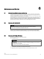
Maintenance and Service ........................................................................................................................ 71
6.1
General about Maintenance and Service.................................................................................... 71
6.2
Cleaning the Central Unit ............................................................................................................ 71
6.3
Cleaning the Wedge Windows .................................................................................................... 71
6.4
Calibration Verification ................................................................................................................ 72
6.5
Reconfiguration of Temperature Compensation ......................................................................... 73
6.6
Reconfiguration of Pressure Compensation ............................................................................... 74
6.7
Reconfiguration of the Path Length ............................................................................................ 75
Spare Parts List ....................................................................................................................................... 77
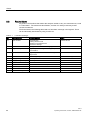
7.1
7.1.1
7.1.2
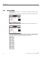
Compatibility of detectors with central units................................................................................ 77
Detector Labels ........................................................................................................................... 77
Central Unit Labels...................................................................................................................... 78
7.2
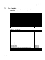
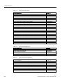
Spare Parts Lists......................................................................................................................... 79
7.3
Ordering Instructions................................................................................................................... 81
7.4
Repair/Upgrade........................................................................................................................... 81
Technical Data......................................................................................................................................... 83
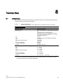
8.1
Central Unit ................................................................................................................................. 83
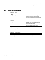
8.2
Hybrid and Sensor Cables .......................................................................................................... 87
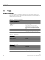
8.3
Purging ........................................................................................................................................ 88
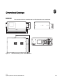
9
Dimensional Drawings ............................................................................................................................. 89
A
ESD guidelines ........................................................................................................................................ 93
A.1
B
ESD guidelines............................................................................................................................ 93
List of Abbreviations ................................................................................................................................ 95
B.1
List of Abbreviations.................................................................................................................... 95
Index........................................................................................................................................................ 99
6
LDS 6
Operating Instructions, 01/2009, A5E00295894-05
General Information
1.1
1
Information for our Customers
Before beginning work with this device, please study this manual carefully! It contains
important information and data whose observation ensures proper device function and saves
you servicing costs. The manual will help you to operate the device more easily and
efficiently, allowing you to achieve reliable results.
1.2
General Information
The product described in this manual has left the factory in a high quality and tested
condition. In order to preserve this condition and to operate this product correctly and safely,
it may only be used in the manner described by the manufacturer. Furthermore, proper
transportation, storage, installation, operation and maintenance of the device is vital for
ensuring correct and safe operation.
This manual contains the information required for the intended use of the described product.
It is addressed to technically qualified personnel who are specially trained or who have the
relevant knowledge of automation technology (measuring and control systems).
Knowledge and technically correct implementation of the safety notes and warnings
contained in this manual are required for safe installation and commissioning, as well as for
safety during the operation and maintenance of the described product. Only qualified
personnel have the required professional knowledge for correctly interpreting the generally
valid safety notes and warnings in this manual in each specific case and to act accordingly.
This manual is an inherent part of the scope of delivery, despite the fact that it can be
ordered separately for logistic reasons.
Due to the variety of technical details, it is not possible to consider every single detail for all
versions of the described product and for every conceivable case in the set-up, operation,
maintenance and use in systems. For further information, or in the case of problems which
are not covered in enough detail in this document, please request the required information
from your local or responsible Siemens regional office.
Note
In particular, before using the device for new research and development applications, we
recommend that you first contact your Siemens representative or our application department
to discuss the application in question.
LDS 6
Operating Instructions, 01/2009, A5E00295894-05
7
General Information
1.3 Special Information and Warnings
1.3
Special Information and Warnings
This manual provides you with information on using, installing, operating, and maintaining
the device.
Pay particular attention to all special information and warnings. Information of this type is set
apart from the rest of the text and is marked with the corresponding pictograms. This
information provides you with useful tips and helps to avoid faulty operation.
1.4
Warranty Conditions
We expressly point out that the product quality is exclusively and conclusively described in
the sales contract. The content of this product documentation is neither a part of a previous
or existing agreement, promise or legal relationship, nor is it intended to modify these. All
obligations on the part of Siemens AG are contained in the respective sales contract, which
also contains the complete and solely applicable liability provisions. The provisions defined
in the sales contract for the responsibility for defects are neither extended nor limited by the
remarks in this document.
1.5
Delivery Information
The respective scope of delivery is listed on the shipping documents – enclosed with the
delivery – in accordance with the valid sales contract.
When opening the packaging, please observe the corresponding information on the
packaging material. Check the delivery for completeness and undamaged condition. In
particular, you should compare the Order No. on the rating plates with the ordering data, if
available.
If possible, please retain the packaging material, since you can use it again in case of return
deliveries.
1.6
Standards and Regulations
As far as possible, the harmonized European standards were the basis for the specification
and production of this device. If no harmonized European standards have been applied, the
standards and regulations for the Federal Republic of Germany are valid.
When this product is used beyond the scope of these standards and regulations, the valid
standards and regulations of the country of the operating company apply.
8
LDS 6
Operating Instructions, 01/2009, A5E00295894-05
Technical Information
2.1
2
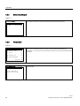
General Description
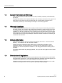
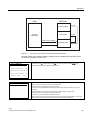
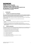
Overview
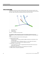
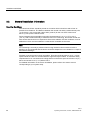
LDS 6 is a diode laser gas analyzer with a measuring principle based on the specific light
absorption of different gas components. LDS 6 is suitable for fast and non-contact
measurement of gas concentrations or temperatures in process or flue gases. One or two
signals from up to three measuring points are processed simultaneously by one central
analyzer unit. The in-situ cross-duct sensors at each measuring point can be separated up to
700 m from the central unit by using fiber-optic cables. The sensors are designed for
operation under harsh environmental conditions and contain a minimum of electrical
components.
Figure 2-1
LDS 6, typical installation with transmitted-light sensors
LDS 6
Operating Instructions, 01/2009, A5E00295894-05
9
Technical Information
2.1 General Description
Benefits
The in-situ gas analyzer LDS 6 is characterized by a high availability and unique analytical
selectivity, and by a broad scope of suitable applications. LDS 6 enables the measurement
of one or two gas components or – if desired – the gas temperature directly in the process:
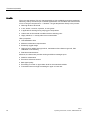
● With high levels of dust load
● In hot, humid, corrosive, explosive, or toxic gases
● In applications showing strong varying gas compositions
● Under harsh environmental conditions at the measuring point
● Highly selective, i.e. mostly without cross-sensitivities
LDS 6 properties:
● Little installation effort
● Minimum maintenance requirements
● Extremely rugged design
● High long-term stability through built-in, maintenance-free reference gas cell, field
calibration is unnecessary
● Real-time measurements
Moreover, the instrument provides warning and failure messages upon:
● Need for maintenance
● Erroneous reference function
● Bad signal quality
● Exceeding of a lower or upper alarm level for the measured variable
● Transmitted amount of light exceeding an upper or lower limit
10
LDS 6
Operating Instructions, 01/2009, A5E00295894-05
Technical Information
2.1 General Description
Application
The LDS 6 laser gas analyzer is suitable for a wide range of applications. The most common
of them are:
● Process optimization
● Continuous emission monitoring for all kinds of fuels (oil, gas, coal, and others)
● Process measurements in power utilities and any kind of incinerator
● Process control
● Explosion protection
● Measurements in corrosive and toxic gases
● Quality control
● Environmental protection
● Plant and operator safety
Sectors
● Power plants
● Steel works
● Cement industry
● Chemical and petrochemical plants
● Automotive industry
● Waste incinerators
● Glass and ceramics production
● Research and development
Special applications
In addition to the standard applications, special applications are available upon request.
LDS 6
Operating Instructions, 01/2009, A5E00295894-05
11
Technical Information
2.1 General Description
Essential characteristics
● Integrated calibration adjustment with an internal reference cell
● Negligible long-term drifts of zero and span
● Dynamic background correction for varying dust loads
● Isolated signal outputs, 4 to 20 mA
● User-friendly, menu-driven operation
● Selectable time constants (response time)
● Two user levels with individual access codes for prevention of unwanted and
unauthorized operations
● Operation according to NAMUR recommendations
● Monitoring of overall optical transmission
● Remote preventive maintenance and servicing via Ethernet/modem
● Straightforward replacement of the central unit, since connections can easily be removed
● Sensor and central unit housing free of wear and corrosion
● Easy operation with a numerical keypad and menu prompting
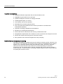
Certified versions for emission monitoring
The LDS 6 is available as certified instrument for emission monitoring of NH3, NH3/H2O, H2O,
HCl, HCl/H2O. The certificates are issued by TÜV for Germany and MCERTS for the United
Kingdom. For conducting regular linearity and calibration checks, test kits for ammonia,
water and HCl should be used. These kits can be ordered separately as instrument
accessories. For new analyzer orders, the NH3, NH3/H2O and H2O kits named "Version 2"
must be ordered. In case of doubt or for already installed analyzers, please contact Siemens
for spotting the correct kit version.
12
LDS 6
Operating Instructions, 01/2009, A5E00295894-05
Technical Information
2.2 Design
2.2
Design
The gas analyzer LDS 6 consists of a central unit and up to three in-situ sensors. The
connection between the central unit and the sensors is established by a so-called hybrid
cable, which contains optical fibers and copper wires. An additional cable connects the
transmitter and receiver parts of the cross-duct sensor.
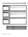
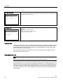
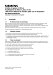
Central unit
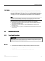
The central unit is housed in a 19" rack with 4 holders for mounting in a hinged frame in
racks with or without telescopic rails.
The LDS 6 operates as an independent unit powered by a 100-240 V AC main power supply.
Figure 2-2
CentralUnit
LDS 6
Operating Instructions, 01/2009, A5E00295894-05
13
Technical Information
2.2 Design
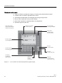
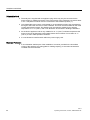
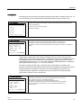
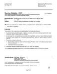
Display and control panel
● Large LCD field for simultaneous display of measurement result and device status
● Contrast of the LCD field is adjustable via the menu
● LED background illumination of the display with energy-saving function
● Easy-to-clean membrane touch pad with softkeys
● Menu-driven operation for parameterization and diagnostics
● Operation support in plain text
/('EDFNOLWJUDSKLF
GLVSOD\DQGPHPEUDQH
WDFWLOHWRXFKNH\ERDUG
6WDWXVOLQHWRLQGLFDWH
WKHGHYLFHVWDWXV
7ZRFRGHOHYHOV
DFFRUGLQJWR1$085
0HQXGULYHQ
RSHUDWRUFRQWURO
ZLWKILYHVRIWNH\V
1XPHULFGLVSOD\
RIFRQFHQWUDWLRQV
(6&NH\
WRFDQFHOHQWULHV
1XPHULFNH\SDG
IRUHQWHULQJGLJLWV
,1)2NH\
IRUKHOSLQSODLQWH[W
&/($5NH\
WRGHOHWHWKH
GLJLWVHQWHUHG
Figure 2-3
14
(17(5NH\
WRDGRSW
WKHQXPEHUV
0($6NH\
WRUHWXUQGLUHFWWR
PHDVXUHPHQWPRGH
LDS 6 central unit, membrane keyboard and graphic display
LDS 6
Operating Instructions, 01/2009, A5E00295894-05
Technical Information
2.2 Design
Inputs and outputs
● One to three measurement channels with hybrid connections for the sensors at the
measuring points
● Two analog inputs per channel for process gas temperature and pressure
● Two analog outputs per channel for gas concentration(s) or for gas temperature and
concentration For selected versions, the transmission can be read out as an alternative.
● Six freely configurable binary inputs per channel for signalling faults or maintenance
requests from external temperature or pressure transducers or sensor purging failure.
● Six freely configurable binary outputs per channel (signalling of faults, maintenance
requirements, function control, transmission limit alarms, concentration limit alarms, store
analog output)
Communication
Network connection: Ethernet (10Base-T) for remote diagnostics and maintenance.
The LDS 6 can be operated remotely via the Ethernet port with a PC running
Windows 95/98/ME or Windows NT/2000/XP. It is also possible to connect the LDS 6 via
modem to the public telephone net. In that case an LDS 6 LAN modem kit is required. Any
external connection requires the optional software LDSComm (LDS Communication Client)
to be installed on the remote computer. All aspects of LDS 6 can be controlled in this way.
For the operation of the LDS 6 using LDSComm software refer to the LDSComm Manual
(A5E02183317).
Maintenance and fault messages
LDS 6 outputs different warnings via relays:
● Need for maintenance (measured value is not influenced)
● Operating error (measured value might be influenced)
LDS 6
Operating Instructions, 01/2009, A5E00295894-05
15
Technical Information
2.2 Design
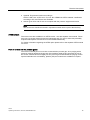
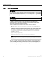
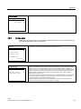
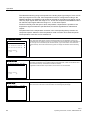
Cross-duct sensors
Figure 2-4
Sensor CD 6, transmitter or receiver unit
● In-situ cross-duct sensors, configured as transmitter and receiver unit, connected via
sensor cable
● Connection to the LDS 6 central unit by a so-called hybrid cable, max. length 700 m
● Stainless steel, partially painted
● IP65 degree of protection for sensor
● Adjustable flanges with flange connection
DN 65/PN 6, ANSI 4"/150 lbs
● Optional flameproof window flanges with dimensions: DN 65/PN 6, DN 80/PN 16, ANSI
4"/150 lbs, other process interfaces available on request
● Purging facilities on the process and the sensor sides, configurable application with
purging gas connections for:
– Instrument air
– Purging air blower
– Steam
– Nitrogen
– Process gases to which the pressure equipment directive cat. 2 does not apply
● In combination with high-pressure window flanges, purging with instrument air or nitrogen
is possible
● Fast connectors for cleaning the measurement openings and the sensor window
16
LDS 6
Operating Instructions, 01/2009, A5E00295894-05
Technical Information
2.2 Design
● Optional: Ex-protected version according to
ATEX II 1GD T135 °C EEx ia IIC T4, Cert. No. DEMKO 06 ATEX 139648X. Certificates
according to IEC and TIIS are also available
● Sensor types CD 6 and CD 6C are compliant with the pressure equipment directive
Note
The sensors are described in detail in separate manuals which is part of their delivery.
ATEX sensors
The sensors are also available in an ATEX version - see also separate user manual. These
have very low power electronics and are intrinsically safe. For use in areas with potentially
explosive atmosphere a barrier box must be installed additionally.
For further information regarding the ATEX option please refer to the separate ATEX manual
for LDS 6.
Parts in contact with the process gases
The sensors normally do not come into contact with the process gas, since purging with a
gaseous media is applied at the process side. Stainless steel purging gas tubes in front of
the sensor windows immerse slightly into the process gas and thus limit the purging volume.
Special materials such as Hastelloy, plastics (PP) and ceramics are available on request.
LDS 6
Operating Instructions, 01/2009, A5E00295894-05
17
Technical Information
2.2 Design
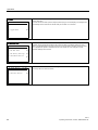
Hybrid and sensor cables
A combination of fiber-optic cables and twisted copper wires connects the sensors to the
central unit. The hybrid cable connects the central unit with the transmitter unit of the sensor,
the sensor cable connects the transmitter and receiver units of the sensor.
3
1
Twisted pair of wires
2
Multimode fiber
3
Singlemode fiber
Figure 2-5
2
1
Connections of the hybrid cable
For installation in EEx-protected environments, the legislative regulations have to be
complied with, such as the spatial separation of intrinsically-safe from non-intrinsically-safe
cables.
● Max. 700 m between central unit and measuring point
● Hybrid and sensor cables
– Multimode fiber-optic cable, provided with SMA connections for transmission of the
measured signal
– Two-wire copper cable, in twisted pair version, for +24 V supply of the detector
electronics (+12 V in the case of EEx-suitable instruments)
● Additionally for the hybrid cable:
– Single-mode fiber-optic cable, configured double-sided with E2000 connectors for
transmission of laser light
● Rugged cable sheath for mounting in open cable ducts or ductworks
● Sheath material: oil-resistant polyurethane
18
LDS 6
Operating Instructions, 01/2009, A5E00295894-05
Technical Information
2.3 Operating Principle
2.3
Operating Principle
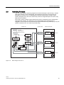
LDS 6 is a gas analyzer employing single-line molecular absorption spectroscopy. A diode
laser emits a beam of near-infrared light, which passes through the process gas and is
detected by a receiver unit. The wavelength of the laser diode output is tuned to a gasspecific absorption line. The laser continuously scans this single absorption line with a very
high spectral resolution.
The result is a fully resolved single molecular line which is analyzed in terms of absorption
strength and line shape. The influence of cross-sensitivities on the measurement is
negligible, since the quasi-monochromatic laser light is absorbed very selectively by only one
specific molecular line in the scanned spectral range.
&HQWUDOXQLW
+\EULGFDEOHV
0HDVXUHPHQWSDWK
/DVHUOLJKW
37
(OHFWULFDOVLJQDOV
0HDVXUHG
YROXPH
5HIOHFWHG/('OLJKW
&38DQG
GLVSOD\
/DVHU
FRQWURO
6LJQDO
SURFHVVLQJ
'LRGH
ODVHU
&KDQQHO
(2
37
(2
37
(2
2SWRFRXSOHU
0HDVXUHG
YROXPH
&KDQQHO
(2
(2
37
5HIHUHQFH
FHOO
37
0HDVXUHG
YROXPH
&KDQQHO
(2
Figure 2-6
Basic design of the LDS 6
LDS 6
Operating Instructions, 01/2009, A5E00295894-05
19
Technical Information
2.4 Configuration Examples
2.4
Configuration Examples
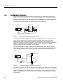
A feature of the in-situ analytical procedure is that the physical measurement takes place
directly in the stream of process gas, and usually also directly in the actual process gas line.
All process parameters such as gas matrix, pressure, temperature, moisture, dust load, flow
velocity and mounting orientation can influence the measuring properties of the LDS 6 and
must therefore be systematically investigated for each new application.
&HQWUDOXQLW
3URFHVVIODQJH
7UDQVPLWWHUXQLW
+\EULGFDEOH
PD[OHQJWKP
*DVFRQFHQWUDWLRQ
)OXHJDV
FRPSRVLWLRQ
6WHDP
'XVWORDG
*DVYHORFLW\
*DVWHPSHUDWXUH
*DVSUHVVXUH
5HFHLYHU
0HDVXUHPHQW
SDWKOHQJWK
6HQVRUFRQQHFWLQJFDEOH
6XSSOHPHQWDU\FKDQQHORSWLRQ
6XSSOHPHQWDU\FKDQQHORSWLRQ
Figure 2-7
Typical transmitted light setup of LDS 6, in-situ
A feature of the standard applications defined in the ordering data of the LDS 6 is that the
typical process conditions are well-known and documented, and that the guaranteed
measuring properties can be proven by reference installations. If you cannot find your
application among the standard applications, please contact Siemens. We will be pleased to
check your possible individual application of the LDS 6. You can find an application
questionnaire on the LDS product sites on the Internet.
To avoid contamination of sensor openings on the process side, clean gaseous purging
media are used such as instrument air, N2 or steam. Purging air tubes on the sensor heads,
which slightly penetrate into the process gas stream, define the effective measuring path
length.
+\EULGFDEOH
PD[OHQJWKNP
6XSSOHPHQWDU\
FKDQQHORSWLRQ
6XSSOHPHQWDU\
FKDQQHORSWLRQ
Figure 2-8
6HQVRUFRQQHFWLQJFDEOH
7UDQVPLWWHUXQLW
&HQWUDOXQLW
6DPSOH
JDV
LQOHW
7HPSHUDWXUH
VHQVRU
6DPSOHJDV
RXWOHW
5HFHLYHU
Typical transmitted light setup of LDS 6, in bypass
The LDS 6 can measure in both the transverse and longitudinal directions of the process gas
flow. In certain cases, the process conditions make it necessary to condition the sample gas
stream in a bypass line with respect to process temperature, pressure and/or optical path
length. Further treatment of the process gas, such as drying or dust precipitation, is usually
not necessary.
20
LDS 6
Operating Instructions, 01/2009, A5E00295894-05
+\EULGFDEOH
PD[OHQJWKP
6XSSOHPHQWDU\
FKDQQHORSWLRQ
6XSSOHPHQWDU\
FKDQQHORSWLRQ
Figure 2-9
2.5
7UDQVPLWWHUXQLW
+HDWLQJ
RSWLRQ
6DPSOHJDVLQOHW
&HQWUDOXQLW
6HQVRUFRQQHFWLQJFDEOH
Technical Information
2.5 Measurement Principle
3XPS
5HFHLYHU
Measuring configuration of LDS 6 with heated flow cell
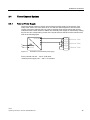
Measurement Principle
Mode of operation
The operation of LDS 6 is based on the fact that light propagating through a gas mixture will
be absorbed according to Beer-Lambert's law at certain narrow wavelength bands. This is
where the gases possess molecular transitions forming narrow absorption lines.
The light source in LDS 6 is a semi-conductor laser tuned to an appropriate absorption line
for the gas to be measured. The laser light is spectrally much narrower than the gas
absorption line and this, together with a proper choice of absorption line, will result in low
interference from other gases.
The light is modulated, both in frequency and in amplitude, to facilitate detection on the
second harmonic as well as elimination of contribution from spectrally broad absorption
originating from dust, smoke, etc.
LDS 6 is connected to the measuring points by fiber optics. The laser light is guided by a
single-mode fiber from the central unit to the transmitter unit of the in-situ sensor. The sensor
consists of a transmitter and a receiver; the distance between them defines the
measurement path. In the receiver box, the light is focused onto a suitable detector. The
detector signal is then converted into an optical signal and transmitted via a second optical
fiber to the central unit, where the concentration of the gas component is determined from
the detected absorption signal.
LDS 6 usually measures a single gas component by means of the absorption capacity of a
single fully resolved molecular absorption line. The absorption results from conversion of the
radiation energy of the laser light into the internal energy of the molecule. In the working
range of the LDS 6, both rotation-vibration transitions and electronic transitions – such as
with O2 – can be triggered.
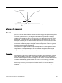
In some specific cases, two components can be measured simultaneously if their absorption
lines are so close to each other that they can be detected within the laser spectrum by one
single scan (for example water (H2O) and ammonia (NH3)).
LDS 6
Operating Instructions, 01/2009, A5E00295894-05
21
Technical Information
2.5 Measurement Principle
1.0
0.9
Relative absorption
0.8
H2O 15%
0.7
0.6
0.5
0.4
0.3
NH3 5ppm
0.2
0.1
0.0
1.543
Figure 2-10
1.5435
1.544
1.5445
1.545
Wavelength [μm]
1.5455
1.546
Absorption spectra of water and ammonia
Moreover, in some applications it is possible to determine the gas temperature as a
measured value. In this case, the ratio of the absorbance of two characteristic lines of the
same molecule measured at the same time in the same volume gives the actual temperature
in the process gas.
Typical measurable gases for LDS 6 are:
● Oxygen (O2) for low and high pressure
● Oxygen + temperature
● Hydrogen fluoride (HF) + water
● Hydrogen chloride (HCl) + water
● Ammonia (NH3) + water
● Water vapor (H2O)
● Carbon monoxide (CO)
● Carbon dioxide (CO2)
● CO + CO2
By using an internal reference cell normally filled with the gas measured, the stability of the
spectrometer is permanently checked in a reference channel.
By doing so, the continuous validity of the calibration is ensured without the need to carry out
external recalibration using bottled test gases or reference gas cells.
22
LDS 6
Operating Instructions, 01/2009, A5E00295894-05
Technical Information
2.5 Measurement Principle
$EVRUSWLRQOLQH
/DVHUOLQH
Figure 2-11
Typical spectral bandwidth of an absorption line compared to the bandwidth of the laser
light
Influences on the measurement
Dust load
As long as the laser beam is able to generate a suitable detector signal, the dust load of the
process gases does not influence the analytical result. By applying a dynamic background
correction, measurements can be carried out without any negative impact. Under good
conditions, particle densities up to 100 g/Nm3 can be handled by the LDS 6. Varying dust
loads are compensated by scanning the laser over the gas absorption line and the current
background. At a scan position next to the absorption line, the instrument can "see" only
absorption caused by the dust load where at the line center the signal is composed of the
molecular absorption and the continuous, unspecific background absorption. With the
wavelength modulation technique, the actual measured transmission is always compared
with the baseline. After signal processing, phase-sensitive application delivers a signal only
from the molecular line free of background.
The influence of a high dust load is complex and depends on the path length and particle
size. The optical damping increases at longer path lengths. Smaller particles also have a
large influence on the optical damping. With a combination of high dust load, long path
length and small particle size, the technical support at Siemens should be consulted.
Temperature
The temperature influence on the absorption line strength is compensated by a correction
factor determined during calibration. A temperature signal can be fed into the instrument
from an external temperature sensor. This signal is then used to correct the influence of the
temperature on the observed line strength. If the temperature of the sample gas remains
constant, it is alternatively possible to carry out a static correction using a preset value.
At high temperatures there may be noticeable broadband IR radiation of gas and dust, or
flames may occasionally occur in the measurement path. In this case the detector is
protected by an optical bandpass filter to prevent saturation by the strong background
radiation.
LDS 6
Operating Instructions, 01/2009, A5E00295894-05
23
Technical Information
2.5 Measurement Principle
Pressure
The gas pressure can affect the line shape of the molecular absorption line. LDS 6 uses a
special algorithm to adapt the line shape. Additionally, an external pressure signal can be fed
to the instrument to provide complete compensation for the pressure influence including the
density effect.
Cross-interferences
Since LDS 6 derives its signal from a single fully resolved molecular absorption line, crossinterferences with other gases are quite unlikely. LDS 6 is therefore able to measure the
desired gas components very selectively. In special cases, the composition of the process
gas might have an influence on the shape of the absorption line features. This influence is
compensated by analyzing the full shape of the detected signal curve applying specific
algorithms.
Optical path length
The absorption values analyzed by the LDS 6 are typically small. As a result of BeerLambert’s law, the absorption of laser light depends on the optical path length within the gas.
Therefore, the precision in determining the effective optical path length in the process might
limit the overall precision of the measurement.
As the sensor openings toward the process normally need to be purged to keep them clean
over a long period of time, the thickness of the mixing zone between the purging medium
and the process gas and its concentration distribution need to be considered. In a typical insitu installation with some meters of path, the influence of the purging gas on the effective
path length can be neglected.
Path length and dust load are mutually influencing: the higher the dust load in the process,
the shorter the max. possible path length.
Note
Individual requirements for the measuring point can make the utilization of special sensor
equipment necessary. The possibilities for adapting the sensors are:
• Different purging media, such as instrument air, ambient air, nitrogen or steam
• Different purging modes on process and sensor sides
• Special materials of purging tubes and/or sensor flanges
• Cooling or heating of the sensors
• EEx-proof sensor configurations
24
LDS 6
Operating Instructions, 01/2009, A5E00295894-05
Installation Guidelines
3.1
3
Safety Information
It is essential that you observe the given information and warnings!
Electrical Safety
DANGER
Certain parts inside the gas analyzer LDS 6 carry dangerous voltages.
The housing must be closed and grounded before switching on the analyzer.
Death, personal injury and/or damage to persons and/or property may result if this is not
observed.
LDS 6 and CD 6 meet all regulations specified in the present EU regulations
(LVD regulation 2006/95/EC and EMC regulation 2004/108/EC).
The device can be used in an industrial environment.
Laser Safety
All lasers used by LDS 6 are of class 1. The emitted laser light is in most cases invisible
(near infrared) and the intensity is low enough so that the unprotected eye is not damaged
under normal circumstances. LDS 6 has warning labels at appropriate positions according to
DIN EN 60825-1.
CAUTION
This device emits laser beams.
To avoid damage to your eyes never look directly into the laser beam.
If this rule is not followed there is a chance that damage to the unprotected eye may occur
if you look directly into the laser beam particularly when using focusing optics (e. g.
binoculars).
LDS 6
Operating Instructions, 01/2009, A5E00295894-05
25
Installation Guidelines
3.1 Safety Information
Heat Safety
Some metal parts and piping placed near the sensors are at elevated temperatures. The
reason is high temperature purging - either from steam or from air.
CAUTION
The sensors are designed for work at elevated temperatures, particularly when a purging
system is in operation. Even after operation these parts cool off slowly.
For any work around these sensors be sure to wear protective gloves.
If this rule is not followed serious burns of the unprotected skin may happen.
Pressure Safety
The sensor is tested at a pressure of 600 kPa. This pressure value should not be exceeded
in operational conditions.
WARNING
Should pressures higher than 600 kPa occur in the process, this can lead to destruction of
the sensors and their environment. In worst case process media may break free and pollute
the environment.
Avoid under any circumstances process pressures higher than 600 kPa.
If this rule is not followed, death, injuries and/or damage to property and environment can
occur.
Explosion Protection - II 1GD T135 °C EEx ia IIC T4 IP65
The LDS 6, with a central unit and sensors interconnected with optical fibers, is explosion
safe. Only a limited, low energy part of the electronics is located at the measurement site.
The distance between the central unit and the sensors can be several hundred meters. The
LDS 6 system is available in an Ex version and is then delivered with an approval for use in
hazardous environments. The ATEX certificate is a system certificate and is only valid if LDS
6 is installed according to the instructions given in the certificate.
26
LDS 6
Operating Instructions, 01/2009, A5E00295894-05
Installation Guidelines
3.1 Safety Information
Approval
The concept of the Ex approval is that the central unit is unchanged from a standard unit and
that a special Ex sensor pair (CD 6 Ex) is used in the hazardous zone. In addition to this an
explosion protection barrier is added before entry into the hazardous zone. An absolute
condition for the approval is that the equipment is set up according to the drawing, ADM
3040 3050, please refer to the separate ATEX manual for LDS 6.
The protection is as follows:
Cross Duct Sensor Central (Barrier) Unit -
II 1G Ex ia IIC T4
II (1)G Ex [ia] IIC
II 1D IP65 T135 °C.
II (1)D Ex [iaD].
● Equipment Group: Group II - Surface.
● Equipment Category: Category 1G D - Zone 0. Flammable material can be present
continuously, frequently or for long periods, in gas and dust.
● Type of protection: EEx ia. The equipment present in the hazardous area is intrinsically
safe.
● Explosion group: IIC. This corresponds to a gas group containing Acetylene and
Hydrogen.
● Temperature class: T4. The maximum surface temperature on the equipment is 135 °C
(275 °F) and the ignition temperature of the gas or vapor is between 135 °C (275 °F) and
200 °C (392 °F).
● The sensor housing protection is IP65 and the ambient temperature must be between
-30 °C (-22 °F) and +60 °C (140 °F) .
Liability
Following commissioning, the total responsibility is with the owner.
LDS 6
Operating Instructions, 01/2009, A5E00295894-05
27
Installation Guidelines
3.2 General Installation Information
3.2
General Installation Information
Mounting Conditions
The central unit LDS 6 should be placed on a location which is dust-free and as free as
possible from vibrations. The distance between the central unit and the measurement point,
i.e. the sensor, may not exceed 1000 meters (3,280 ft) for the non ATEX version and
600 m (1,970 ft) for the ATEX version.
During operation the permissible surrounding air temperature is 5 °C (41 °F) to 45 °C
(113 °F), with a relative humidity of maximum 85% non-condensing, around the central unit.
Also ensure that the unit is not exposed to direct solar radiation. If these conditions can’t be
fulfilled the LDS 6 must be installed in a cabinet with controlled environment.
Note
As condensing is normally a problem when moving the device from outside to inside a
building it is recommended that the device should be adapted to room climate for a couple of
hours before starting it.
The back of the unit must be freely accessible. There should be at least 10 cm (4 ") of free
space behind the LDS 6 to accommodate the signal and hybrid cables. To meet the safety
requirements for air convection and cooling there must be a free space of at least 5 cm (2 ")
above and at least 3 cm (1 1/4 ")below LDS 6.
For detailed information on the sensor installation, please refer to the sensor manual
corresponding to your system setup.
28
LDS 6
Operating Instructions, 01/2009, A5E00295894-05
Installation Guidelines
3.3 Electrical Connections
Hybrid Cables
The hybrid cables should be installed such that they are protected from mechanical wear
such as sharp edges or moving parts. During installation always keep the protective tube in
such a position that the single mode fiber connector is protected from dust. The operating
temperature for the cables is -40 to +80°C (-40 to 176 °F) and the installation temperature is
-20 to +80°C (-4 to 176 °F). The bending radius of the cables may never be smaller than
100 mm (4 ").
Note
Throughout the entire installation, keep the fiber ends protected by the protective tubes;
observe that these should only be removed by authorized personnel.
There are three kinds of cables used for the LDS 6 depending on the application:
● Hybrid cables for all types of systems except oxygen. These are installed between the
LDS 6 and the transmitter sensor.
● Hybrid cables for oxygen systems only, also installed between the LDS 6 and the
transmitter sensor.
● Loop cables, same for all systems, are installed between the transmitter sensor and the
receiver sensor.
3.3
Electrical Connections
3.3.1
Power Supply Connections
WARNING
The respective country-specific standards for the installation of power systems with rated
voltages below 1000 V must be followed. Failure to observe these regulations may result in
death, personal injury and/or damage to property.
General
● Check that the local voltage agrees with that specified on the label on the analyzer.
● The cable must be tested according to IEC 60227 or IEC 60245 and must be suitable for
70 °C (158 °F).
● The power cable must be routed separately from the hybrid cables.
LDS 6
Operating Instructions, 01/2009, A5E00295894-05
29
Installation Guidelines
3.3 Electrical Connections
Detachable Cord
● The analyzer is supplied with an appliance plug which may only be connected to the
power supply by qualified personnel. The cross-section of the conductors must be at least
1 mm2. The phase conductor must be connected to the identified position (L).
● Only detachable power supply cords tested by an accepted third party Lab accredited for
the region where the unit is to be used is allowed. This cord must be suitable for the rated
current and limited in length. This flexible cord must also be suitable for an ambient
temperature of 70 °C (158 °F) and is not allowed to be mounted in building installations.
● As the kind of appliance inlet is only suitable for 70 °C (158 °F) ambient temperature the
power cord must be kept away with suitable means from surfaces of more than 70 °C
(158 °F) at max. rated operation conditions.
● It is not allowed to install a switch within the power supply cord.
Electrical Protection
● A circuit-breaker shall be part of the installation. It must be provided in the immediate
vicinity of the analyzer (see rating plate for loading capacity). It must also be labeled to
correlate with the instrument.
30
LDS 6
Operating Instructions, 01/2009, A5E00295894-05
Installation Guidelines
3.3 Electrical Connections
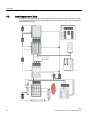
3.3.2
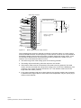
Hybrid Cable Connection
The hybrid cable is connected at the back of the central unit, where its two optical cables and
the supply line for the sensor wire are attached, as shown in the picture below.
1
Figure 3-1
2
3
4
5
6
LDS 6 cable connections (here only channel 3 is connected)
WARNING
Keep the fiber end protected, by the protective tube, until it is time for connection. Only
authorized personnel are entitled to remove the protective tube and proceed with the
connecting operation.
1. Hybrid cable holder.
2. E2000 Single Mode fiber connector, angle polished.
3. SMA Multi Mode fiber connector.
4. Sensor voltage supply connection. 24 V/60 mA.
5. Signal output connections.
6. Network connection. Ethernet 10Base-T (RJ-45).
See also
Pin Assignment of LDS 6 (Page 34)
Signal Cable Connection (Page 32)
LDS 6
Operating Instructions, 01/2009, A5E00295894-05
31
Installation Guidelines
3.3 Electrical Connections
3.3.3
Signal Cable Connection
CAUTION
The signal voltages must be electrically isolated extra-low voltages (SELV). The maximum
voltage potential accessible to persons is 33 Veff or 46,7 V peak or 70 V dc. If several SELV
voltages are available, then it is possible that the sum of these potentials is higher than that
allowed to get in contact with the human body.
WARNING
The signal cables must only be connected to devices which guarantee safe isolation from
their power supply.
If signals (i.e. analog output 4-20 mA) are to be routed into a potentially explosive
atmosphere of zone 1, they must be intrinsically safe. Supplementary retrofitting of the
analyzer with energy-limiting modules is necessary.
The Ex identification of these modules must be clearly visible on the housing:
● The signal cables in the rack mount analyzer are connected to the DSUB plugs at the
rear.
● RC elements must be connected according to the figure "Spark suppression" below as a
measure to suppress the generation of sparks across the relay contacts (i.e. limit relays).
Note that the RC element results in a drop-out delay for an inductive component (i.e.
solenoid valve). The RC element should therefore be dimensioned according to the
following rule-of-thumb:
R [Ω] ≅ 0.2 x RL [Ω] C [µF] ≅ IL [A]
Additionally, make sure that you only use a non-polarized capacitor C.
Note
When using direct current, it is possible to fit a spark suppression diode instead of the RC
element.
The cables to the relay outputs and binary inputs as well as the analog inputs and outputs
must be screened. They must be connected to the corresponding trapezoidal DSUB plug
according to the diagram "Pin assignments for I/O connectors". The conductor cross-section
should be 0.5 mm2. It is recommended to use cables of type JE-LiYCY... BD. The cable
length of the analog outputs depends on the load.
32
LDS 6
Operating Instructions, 01/2009, A5E00295894-05
Installation Guidelines
3.3 Electrical Connections
68%')FRQQHFWRU
0
3RZHUVXSSO\9PD[
5
,/
5/
&
5>˖@[5 />˖@
&>˩)@, />$@
0
Figure 3-2
Spark suppression on a relay contact
The preceding figure shows an example of measure to suppress sparks on a relay contact.
Since the DSUB connector and the spacings on board and on connector are only suitable for
detachable voltages (signal) and as the power is located outside this powers supply, circuit
must be SELV and the power must be limited according to EN61010-1 (Table 13 or 14)
when an over current protective device is used.
● The reference ground of the analog inputs is the housing potential.
● The analog outputs are floating, also with respect to one another.
● The interface cable must be screened and connected to housing potential. The cable
screen must be connected with a large-area contact to the screen of the DSUB plug. The
conductor cross-section should be at least 0.5 mm2. The interface cable must not be
longer than 500 meters (1,640 ft).
● In the case of analyzers with two or three channels, the analyzer sections are connected
in parallel and the signal cables of each channel are independent. Only the power plug is
common to all channels.
LDS 6
Operating Instructions, 01/2009, A5E00295894-05
33
Installation Guidelines
3.3 Electrical Connections
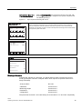
3.3.4
Pin Assignment of LDS 6
The signal connection is carried out by using two DSUB connectors for each channel – one
15 pins and one 25 pins.
Connector SUB-D 15F
GND
15
14
13
12
GND
11
GND
10
GND
9
8
7
6
5
4
3
2
1
GND
Analog output 2-P
Analog output 2-N
Analog output 1-P
Analog output 1-N
NC
GND
Analog input 2-P
Analog input 2-N
Analog input 1-P
Analog input 1-N
Binary input 6-P
Binary input 5-P
Binary inputs 5 to 6-N
GND
Analog outputs:
floating
(also to one another),
RL ≤ 750 Ω
Pressure correction
Pressure correction
Temperature correction
Temperature correction
Component 2
(if present)
Component 1
Non-floating
analog inputs
Floating via opto isolator
"0" = 0 V (0 to 4.5 V)
"1" = 24 V (13 to 33 V)
Connector SUB-D 25F
GND
13
25
24
23
22
21
20
19
18
17
16
15
GND
Figure 3-3
34
14
12
11
10
GND
Binary input 4-P
Binary input 3-P
Binary input 2-P
Binary input 1-P
Binary inputs 1 to 4-N
Floating via opto isolator
"0" = 0 V (0 to 4.5 V)
"1" = 24 V (13 to 33 V)
Relay 6
9
8
7
Relay 5
Relay 4
6
5
4
Relay 3
The relay is de-energized in
the shown contact position
Relay 2
3
2
Relay 1
1
GND
Contact loading
max. 24 V/1 A, AC/DC
Pin assignment for I/O connections
LDS 6
Operating Instructions, 01/2009, A5E00295894-05
Installation Guidelines
3.4 Three Channel System
3.4
Three Channel System
3.4.1
External Power Supply
The three channel version of LDS 6 uses an external power supply for the sensors. The
setup at the sensor site is the same as for one and two channel systems. Also the ATEX
version of the three channel LDS 6 is using an external power supply leaving the sensors
unaffected when a third channel is added. The external power supply is connected by adding
the pins into two corresponding screws of the 6 pole socket at the back of the central unit as
seen in the following figure.
24 V DC
+V
Fuse
-V
L
N
100-240 V AC
Figure 3-4
Schematics of the external power supply.
+
ದ
+
ದ
+
ದ
CH 1 24 V DC
CH 2 24 V DC
CH 3 24 V DC
Fuses: Central unit:100 ... 240 V: T2.5L250V
External power supply:100 ... 240 V: T1.25L250V
LDS 6
Operating Instructions, 01/2009, A5E00295894-05
35
Installation Guidelines
3.4 Three Channel System
3.4.2
Three Channel Hybrid Cable Connection
In a three channel instrument, the electrical wires in the hybrid cables are connected
according to the following figure.
6 pole screw socket for 24 V external power
supply (2 poles per sensor). Note that the
polarity is not important for non ATEX use
whereas it is for ATEX.
+–+–+–
Figure 3-5
Connection of electrical cables for a 3 channel unit
CAUTION
The instrument is not designed to feed 3 sensors using the internal power supply.
36
LDS 6
Operating Instructions, 01/2009, A5E00295894-05
Installation Guidelines
3.5 Flange Installation Requirements
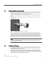
3.5
Flange Installation Requirements
Before the gas analyzer and its sensors can be used, a pair of process flanges should be
installed at the measurement site. The flanges must be installed at a safe and accessible
position to make installation and service easy to accomplish.
The flanges should be welded to the wall of the furnace or funnel as shown in the figure
below.
The flange must protrude at least 100 mm (4") from the wall and 0-30 mm (0-1.2") into the
furnace/funnel.
Figure 3-6
Sensor CD 6 mounted on a process flange
There are applications where furnace walls move due to variations in temperature. If the
furnace walls move the sensors will be miss-aligned and the measurement interrupted. To
overcome this, the sensor can be fixed to a girder or other structure that is not influenced by
the temperature and the flexible metal tube is fitted between the process flange and the
sensor flange. Remember that the flanges fitted for the sensors must not deviate more than
±2°.
Note
It is very important that the flanges are mounted so that they are aligned. Otherwise the
measurements will not be correct.
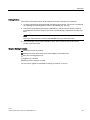
3.6
Installation of Flanges
When welding the flange tubes it is recommended to have the Flange Alignment Kit. The
Flange Alignment Kit from Siemens consists of a light source, two flanges, an aiming tool
and a battery charger for the light source.
Make sure there is enough room for the sensor. Especially take into consideration that it
should be easy to mount or dismount and that the sensors lid should be able to open fully.
Safe working space around the sensors are also needed, guardrails, ladders, etc. The figure
below illustrates the process for installation of flanges.
LDS 6
Operating Instructions, 01/2009, A5E00295894-05
37
Installation Guidelines
3.6 Installation of Flanges
Alignment procedure.
2
2
3
1
4
Figure 3-7
Usage of the items in the flange alignment kit
1. Light source
2. Alignment flanges
3. Aiming tool
4. Process flange to be aligned
This is the alignment procedure
1. Weld the flange tubes loosely on each side of the wall. Do not weld them so hard that the
angle of the tubes can not be adjusted with a hammer.
2. Mount the light source on one flange and the aiming tool on the other flange.
3. Turn on the light source.
4. Adjust the focus on the aiming tool until the light spot from the light source is sharp.
5. Adjust the angle of the process flange tube, using for instance a rubber hammer, until the
light spot is centered on the cross hair on the aiming tool.
6. Weld the aligned flange tube permanently into this position.
7. Shift light source and aiming tool and repeat the procedure above for the opposite flange
until the other tube also is permanently welded.
Note
It is important that the flanges are aligned from both sides. Therefore, remember to shift
light source and aiming tool and repeat the procedure from the other side as well. It is
also important that the sensor flanges are oriented in such a way that the spring loaded
bolts are located in the lower section of the flange.
38
LDS 6
Operating Instructions, 01/2009, A5E00295894-05
Installation Guidelines
3.6 Installation of Flanges
Flange Alignment Deviation
When both flange-tubes are permanently fixed the deviation from the theoretical optical path
must not exceed ±2°. This is because the alignment flanges can be adjusted maximum ±2°.
See the figure below.
$SSUR[PP
PLQPP
2
1
0D[LPXPGHYLDWLRQ
2°
:DOOWKLFNQHVV
LQFOXGLQJLQVXODWLRQ
0HDVXUHPHQW$WREHPHDVXUHGDIWHULQVWDOODWLRQ
Figure 3-8
Customer flange alignment
The required precision of the flange alignment
The aim should always be to achieve the best possible alignment of the flanges, i.e. to get
the center of the dot as close as possible to the center of the crosshair on the alignment tool.
This will allow for small changes, for example caused by thermal movement later on.
For a normal installation using standard 400 mm purging tubes the alignment is usually good
enough if the center of the dot is within 3 mm from the center. The lines closest to the center
of the crosshair are about 3 mm from the center.
Note
If long purging tubes will be used, a greater effort should be made to align the flanges
perfectly. Depending on the diameter and length of the stubs the possibility to align the
sensors is more restricted when long purging tubes are used.
LDS 6
Operating Instructions, 01/2009, A5E00295894-05
39
4
Operation
4.1
General
Once the installation of the sensors at the measurement points is done and the connection
via hybrid cables to the LDS 6 is established, the system is ready to be used. The functions
in the LDS 6 are controlled through a keypad on the front of the panel. A 5" LCD screen is
used to present the measurement values as well as the instrument’s interface - the MMI.
Note
In the following screen examples the application illustrated is mainly for the gas NH3
(ammonia). However they are valid for all applications and gases.
3
2
4
5
6
LIM STO CTRL TR
1
CODE
mg/Nm3
NH3 X
Ch1
H2O X
Ch1
NH3 X
Ch2
H2O X
Ch2
%
mg/Nm3
%
LIM STO CTRL TR
+/-
0
Figure 4-1
7
8
9
4
5
6
1
2
3
CODE
CLEAR
ESC
INFO
ENTER
MEAS
The keypad and the screen on LDS 6
1. Measured value.
2. Status display: LIM means: limit (alarm) signaling is idle and
has been triggered.
LDS 6
Operating Instructions, 01/2009, A5E00295894-05
LIM means: limit (alarm)
41
Operation
4.1 General
3. Status line (can be parameterized using function 53). If a fault occurs during operation,
the message "Maintenance request" or "Fault" appears in the status line depending on
the importance of the fault. This message is displayed alternately with the status
messages.
4. Unit display.
5. Measured component display.
6. Function keys with adaptive meaning (soft keys).
Points 1 to 6 apply to channel 1. The elements are repeated in an analogous manner in the
bottom half of the display for a two-channel analyzer (as shown).
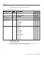
Table 4- 1
Table Op. 1
Switches/Keys
42
Meaning
CLEAR
Deletes a commenced number input.
ENTER
Every digit input (except fast selection of a
function) must be confirmed by using this key.
ESC
Return by one step in the input structure.
Modifications are imported.
INFO
Help information.
MEAS
Return from any position in the input structure to
service mode (possibly with request whether to
import the entered data).
Pressing the MEAS key again results in locking of
the analyzer; i.e. changing to service mode again
is only possible following input of the code.
Soft key
Possible adaptive meanings:
Selection of item in menu tree
Selection of function
Switch function ON/OFF
Component selection
LDS 6
Operating Instructions, 01/2009, A5E00295894-05
Operation
4.1 General
Editing Entries
The values in the menus shown in this chapter should be understood as examples.
● An active input field is represented with brackets ([10]) as limiter. The cursor is positioned
as a flashing line underneath the number to be entered (e.g. [23.45]).
● The input is terminated by pressing the ENTER key, and the value is stored. If several
input fields are present in a menu, the cursor is automatically positioned to the next input
field.
Note
Each input value must be confirmed with ENTER before you leave the menu.
● The CLEAR key can be used to delete an input. The cursor then returns to the first
position of the input field.
Graphic Styling Elements
Switching function (ON status).
Switching function (OFF status, also status display in the status line).
Entry into a subsequent menu.
Triggering of a function.
Measuring mode: analyzer is coded.
Service mode: signals are activated according to functions 71 and 77.
LDS 6
Operating Instructions, 01/2009, A5E00295894-05
43
44
7
Calibration
Measuring Range
Parameters
H2O
NH3
H2O
ch2
ch2
ch1
ch1
No
Only following modifications
If NO, changes will be
used in current session
until restart or reset.
4
To Meas. Screen
Save current modifications?
Yes
Start from
measuring mode
Measuring mode
9
oLIM oSTO oCTRL oTR oCODE
63.28 mg/Nm
11.13 %vol
63.28 mg/Nm
11.13 %vol
3
6
Configuration
Main Menu
Analyzer Status
NH3
1
Service mode
Relay
"Function control"
(CTRL, function 71)
Input of
password
2
Code
2
5
Store for
analog output
(function 77)
Function Menu
Hard keys
Function
Soft keys
4.2
oLIM oSTO oCTRL oTR oCODE
8
Operation
4.2 Input Sequence of Data
Input Sequence of Data
The figure "Input sequence interacting with LDS 6" below shows the input sequence of LDS
6. The circled numbers marking certain steps in the input sequence can also be found in the
text following the figure.
Coding of analyzer
LDS 6
Operating Instructions, 01/2009, A5E00295894-05
Operation
4.2 Input Sequence of Data
Entry into Main Menu for a
1- or 2-Channel System
Figure 4-2
Input sequence interacting with LDS 6
Entry into Main Menu for a
3-Channel System
LIM
STO
11.28
11.13
LIM
STO
12.53
10.13
LIM
STO
CTRL
mg/Nm3
%
TR
CODE
NH3
Ch1
CTRL
CODE
TR
mg/Nm3
%
NH3
Ch2
CTRL
CODE
TR
The appearance of the screen menu varies depending on the number of channels and the
number of measured components. For a 3-channel system the soft keys of the measuring
screen are assigned to channels instead of measured components. If the channel has two
components it is necessary to pass a second channel-specific measuring screen before entering
the component-specific main menu.
NH3
Ch3
mg/Nm3
%
5.28
15.13
Whilst in Measuring Mode, the component is shown on the right, with
an arrow ( ). A soft key ① is assigned to this specific component and
it is called by pressing it.
Each channel can be operated independently.
Channel 1
11.28
11.13
LIM
STO
mg/Nm3
NH3
%vol
H2 O
CTRL
TR
CODE
Main Menu
Main Menu
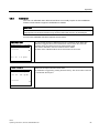
The main menu consists of the five items shown in the adjacent screen.
Ch1 NH3
Analyzer Status
Calibration
Measuring Range
Parameters
Configuration
Entering a Submenu
Following the selection of a submenu, you will be asked to enter a password for service
mode ② (exception: submenu "Analyzer status" which requires no password and is thus
freely accessible).
Analyzer status
No code
Calibration
Access level 3
Measuring ranges
Access level 1
Parameters
Access level 1
Configuration
Access level 2
The passwords for levels 1 and 2 are factory-set to the values "111" and "222" respectively.
LDS 6
Operating Instructions, 01/2009, A5E00295894-05
45
Operation
4.2 Input Sequence of Data
Return to Measuring Screen
To Meas. screen
When pressing the MEAS key you return immediately to the measuring screen from any position
in the menu structure ③. Any input started is aborted.
Ch1 NH3
Save current modifications?
Yes
No
If NO, changes will be
used in current session
until restart or reset.
The adjacent question is displayed before the return is carried out. The modifications are
imported into the working area of the parameter memory by pressing "Yes".
By pressing "No" the modifications are nevertheless used in the working area of the parameter
memory and are valid for the current session. To reject the modifications a restart of the
instrument is required.
The ESC key leads back step-by-step to measuring screen ⑤. Modifications are imported
without questioning ⑥.
Coding of Analyzer
After returning to measuring screen using ESC or MEAS, the symbol CODE in the status
line shows that the analyzer is still in service mode ⑦. The analyzer can be coded again (
CODE) by pressing the MEAS key once more ⑧, thus entering Measuring Mode ⑨.
Simultaneously with the symbol CODE the symbol CTRL (Function control) appears in
the status line, showing that the analyzer is not in measuring mode. External signaling via a
relay contact is then possible if a corresponding relay has been configured with CTRL under
function 71.
Fast Selection of Functions
A "Power user" input has been incorporated to allow immediate switching from the
measuring display to the desired function display if frequent inputs are necessary. It is then
possible to directly access the desired function by bypassing the menu levels. The "Power
user" input can only be started from the Measuring Screen and comprises the following input
steps:
● Enter number of desired function in measuring screen using the digit keys;
● Press the soft key next to the desired component;
● If you do not have the required privileges to change the desired function you will be
requested to enter the password.
For a channel with two components on a three-channel instrument you must first press the
soft key next to the desired channel and thereafter (in the next window) press the soft key
next to the desired component.
46
LDS 6
Operating Instructions, 01/2009, A5E00295894-05
Operation
4.3 Analyzer Functions
4.3
Analyzer Functions
4.3.1
Summary of Analyzer Functions
The analyzer functions can be divided into the following three categories:
● Analyzer-specific functions act on all channels and components of the analyzer,
independently from the analyzer component through which the function was called.
● Channel-specific functions act on all components of the corresponding channel,
independently from the analyzer component through which the function was called.
● Component-specific functions act on a single component, and can only be called through
this.
LDS 6
Operating Instructions, 01/2009, A5E00295894-05
47
Operation
4.3 Analyzer Functions
The following table summarizes the functions of the analyzer.
Table 4- 2
Summary of Analyzer Functions
Main menu item (section)
Function
number
Function designation
1*
2*
5.2.1
Analyzer Status
1
2
3
4
Analyzer Configuration
Diagnostics Values
Logbook
Display Measuring Ranges
x
x
x
x
5.2.2
Calibration (code 3)
20
21
Zero Calibration
Span Calibration
5.2.3
Measuring Range (code 1)
41
Define Ranges
x
5.2.4
Parameters (code 1)
50
51
52
53
55
56
58
60
Response Time
Limits
Transmission
Status Messages
Select Display Digits
LCD Contrast
Date/Time
Setup Logbook
x
x
70
71
72
73
74
75
77
79
81
80
82
83
84
85
86
87
88
89
Analog Output
Relay Outputs
Binary Inputs
Communication
Reset
Save/Load Data
Store Analog Output
Codes Input Levels
Select Language
Analyzer Test
Pressure Correction
Temperature Correction
Water Correction
Path Length
Unit
Dry Gas On/Off
Error On/Off
Ethernet On/Off
5.2.5
Configuration (code 2)
x
x
x
x
x
x
x
x
x
x
x
x
x
x
x
x
x
x
x
x
x
x
x
x
3*
x
x
1* Analyzer-specific functions.
2* Channel-specific functions.
3* Component-specific functions.
Some of the existing functions in other Siemens analyzers are not present in LDS 6, thus
some function numbers may be missing in the preceding table.
48
LDS 6
Operating Instructions, 01/2009, A5E00295894-05
Operation
4.3 Analyzer Functions
4.3.2
Analyzer Status
Table 4- 3
Analyzer Status
Ch1 NH3
1 Analyzer Configuration
This display appears when pressing the first soft key ("Analyzer Status"), following the
selection of the diagnostics functions in the main menu.
The status functions are freely-accessible. You will not be asked to enter a password.
2 Diagnostics Values
3 Logbook
4 Display Meas. Range
1 Analyzer Configuration
You can use this function to display important manufacturing data of the analyzer.
1 Analyzer Config. Ch1 NH3
Order No.
7MBXXXXXXXXXXXXXXXXX
Serial No.
60001
Software Package Version
23
OS Version
3 .0 .126
CE Software
1 .0 .314
CE Drv.Software
2 .3 .245
...Continue X
● Ordering No: Information on ordering data of analyzer.
● Serial No: Consecutive number of analyzer.
● Software Package Version: Version number of the application-specific configuration
software.
● OS Version: Version number of the Windows CE operative system running in the
analyzer.
● CE Software: Version number of the LDS 6-specific software.
● CE Driver Software: Version number of the driver software.
● Analyzer uC Drv.Software: Version number of the software running on the main micro
controller.
● Channel uC Drv.Software: Version number of the software running on the measurement
channel micro controller.
● Opto uC Drv.Software: Version number of the software running on the opto module micro
controller.
● Chan. FPGA Firmware: Version number of the firmware running on the measurement
channel FPGA.
● Opto. FPGA Firmware: Version number of the firmware running on the laser controller
FPGA.
● Ref. FPGA Firmware: Version number of the firmware running on the reference channel
FPGA.
LDS 6
Operating Instructions, 01/2009, A5E00295894-05
49
Operation
4.3 Analyzer Functions
2 Diagnostics Values
2 Diagnostics Val. Ch1 NH3
Absolute Transmission
101.3 Units
Relative Transmission
98.00 %
You can use this function to display internal diagnostic values. These may be of
interest when assessing faults or for adjustment operations.
The absolute transmission is expressed in arbitrary units.
The relative transmission is expressed as a percentage of the nominal value.
The temperature and pressure reflect the measured or set conditions at the
measurement point, and the measuring path the effective length of the path.
Temperature
314.0 °C
Pressure
1013 mbar (absolute)
Measuring Path
1.000 m
Table 4- 4
3 Logbook
3 Logbook
Ch1 NH3
S1
13-11-03 16:43 +
Optomodule Fault
S1
13-11-03 16:37 +
Optomodule Fault
W3
12-11-03 23:55 Signal quality
W3
12-11-03 23:54 +
Signal quality
...Continue X
Page 1
You can use this function to display logged messages. Any event which leads to a
maintenance request (W) or fault message (S) is listed in the logbook (for a more
detailed description of error handling see the chapter Alarms.
Limit alarms (LIM), transmission alarms (TR), and function check (CTRL) are also
recorded. However, these do not trigger a maintenance request or fault message.
The soft key can be used to acknowledge the respective fault entry. The dot will then
disappear. A "+" sign at the end of the entry means an activated alarm, a "-" sign an
inactivated alarm.
The logbook contains a maximum of ten pages, each of which can accommodate four
messages. It operates according to the principle of a circulating buffer, i.e. the oldest
message is overwritten when all ten pages are full (40 messages). Fault messages
are not deleted if they have not been acknowledged.
The logbook entries can be deleted or blocked (function 60), or also switched off
individually (function 88).
Note
If a fault occurs when the error message is switched off by function 88, there is no reaction at
the interface. This applies to the analog as well as to the relay outputs.
4 Display Measuring Ranges
4 Disp. Meas.Range Ch1 NH3
Start
0.00
End value
100.0
mg/Nm3
You can use this function to display measuring ranges. However, you cannot use this
menu to modify the measuring ranges. To do so use function 41. The follwoing
parameters are displayed.
Start Value
This value corresponds to a 4mA current on the analog output.
End Value
This value corresponds to a 20mA current on the analog output.
See also
Alarms (Page 65)
50
LDS 6
Operating Instructions, 01/2009, A5E00295894-05
Operation
4.3 Analyzer Functions
4.3.3
Calibration
The LDS 6 is calibrated when delivered and does not normally require on site recalibration.
Please consult Siemens support if recalibration is needed.
CAUTION
Never use functions 20 and 21 without having contacted Siemens service staff first.
Inappropriate use of these functions may seriously affect the accuracy of the analyzer.
Access to the calibration functions requires access code 3.
20 Zero Calibration
20 Zero Calib.
Ch1 NH3
Zero Calibration Active
The status of the calibration will be shown at the bottom of the screen.
Calibrate
Act. Val.
You can use this function to calibrate the zero of a measuring range. When zero
calibration is triggered the current measurement value is stored. This value will
thereafter always be subtracted from the measurement signal.
Only start the calibration, when the measured value is stable.
0.12 mg/Nm3
21 Span Calibration
21 Span Calib.
Ch1 NH3
Setpoint
293.0 mg/Nm3
Act. Val.
288.1 mg/Nm3
You can use this function to calibrate the span setpoint of a measuring range. This
display lists the setpoint and the current value.
The calibration is triggered by pressing the third soft key. The current value is then set
to coincide with the set point.
Calibrate
LDS 6
Operating Instructions, 01/2009, A5E00295894-05
51
Operation
4.3 Analyzer Functions
4.3.4
Measuring Ranges
Table 4- 5
41 Define Ranges
41 Define Ranges
You can use this function to define a measuring range by assigning a start-of-scale value to the
bottom value (4 mA) and a full-scale to the top value (20 mA) of the analog output.
Ch1 NH3
Start Value End Value
0.000
100.0 mg/Nm3
4.3.5
Parameters
Table 4- 6
Parameters
Ch1 NH3
50 Response Time
51 Limits
This display, showing the selection of the parameter functions 50 to 53 appears following the
selection of the parameter functions in the main menu by pressing the fourth soft key
("Parameters"). You can branch to the parameter functions 54 to 60 by pressing the fifth soft key
(...Continue).
52 Transmission
53 Status Messages
...Continue
50 Response Time
50 Response Time
Ch1 NH3
You can use this function to set various time constants to reduce or suppress noise in the
measured signal.
[5.000] Seconds
Actual Measured
Value: 63.28 mg/Nm3
52
LDS 6
Operating Instructions, 01/2009, A5E00295894-05
Operation
4.3 Analyzer Functions
51 Limits
51 Limits
Ch1 NH3
Upper Limit[30.00] mg/Nm3
Lower Limit 0.00
mg/Nm3
The limit alarm is displayed on the status line if this has been set up by function 53. The alarm is
also signalled by a relay if one has been assigned using function 71. The triggering of a limit
alarm is registered in the logbook (function 3).
Ch1 NH3
You can use this function to set the transmission parameters. A transmission alarm is triggered
when the transmission is outside a permissible range. The lower alarm level of the transmission
for a channel is set as a percentage of the nominal transmission value, where the nominal value
is registered when the fourth soft key is pressed. The upper alarm level is set to a fixed value
and cannot be changed by the user.
Limit Alarm On/Off
52 Transmission
52 Transmission
Alarm Level[5
You can use this functions to set concentration limits. A limit alarm will be triggered when the
value of a component exceeds the permissible range set in this screen. The alarm can be turned
off here.
] %
Nominal
301.2
Units
Absolute
285.0
Units
Relative
84.93
%
Set Nominal Value
The transmission alarm is displayed on the status line if this has been set up by function 53. The
alarm is also signalled by a relay if this has been set up by function 71. The triggering of a
transmission alarm is registered in the logbook
(function 3).
Transm. Alarm On/Off
53 Status Messages
You can use this function to display - within the status line - up to four different statuses which
can be assumed by the analyzer.
53 Status Messages Ch1 NH3
Display Stored Value
[STO]
Display Limits
[LIM]
Display Func. Control
[CTRL]
Display Transm. Limits
[TR]
Table 4- 7
Op. 3
Function
Status
STO: Stored Value
Analog output connected to memory (see also function 77).
LIM: Limit
Upward or downward violation of limit (see also function 51).
CTRL: Function Control
Start-up mode - Service mode.
TR: Transmission
Upward or downward violation of transmission limit (see also
function 52).
LDS 6
Operating Instructions, 01/2009, A5E00295894-05
53
Operation
4.3 Analyzer Functions
55 Select Digits
You can use this function to select the number of decimal digits. The number of digits, including
the decimal point, is always five when setting the function to automatic.
55 Select Digits
Ch1 NH3
Supress Negative
Values
You can also use this function to suppress the output of negative values on the measuring
screen.
Digits After Automatic
Decimal Point
56 LCD Contrast
You can use this function to adjust the display contrast.
56 LCD Contrast
Ch1 NH3
Brighter
If the contrast is maladjusted you can re-establish the factory settings by pressing the third soft
key ("Basic setting").
If the LCD contrast is extremely maladjusted, and if the analyzer is in measuring mode, you can
also re-establish the basic setting by pressing the following key sequence: 8888 ENTER
Darker
In addition you can carry out an LCD test by pressing the fourth soft key ("Test"). Various test
patterns are then shown in succession. The test can be stopped by pressing ESC.
Basic Setting
Test
58 Date/Time
You can use this function to set the actual date and time.
58 Date/Time
Ch1 NH3
New Date(dd-mm-yy;24h/day)
[01-04-04]
New Time (hh-mm; 24 h):
14:44
The analyzer has a system clock which is not protected against power failure (not a real-time
clock). The clock is set at 01-01-00 00:00 when the analyzer is started.
This function allows you to exactly set the date and time. This is particularly important when you
need to assign a specific point in time to faults stored in the logbook. This can be helpful when
troubleshooting.
Set Clock
After selection of this function an editing field appears in which you can enter day, month and
year as "New date". Hours (24-hour system) and minutes are entered as "New time".
Actual Date
Actual Time
01-04-2004
14:44
The set data are imported when you press the third soft key ("Set Clock"). The data then appear
as an active display at the bottom of the screen.
Note
Date and time must be reset in case of a power failure.
54
LDS 6
Operating Instructions, 01/2009, A5E00295894-05
Operation
4.3 Analyzer Functions
60 Setup Logbook
60 Setup Logbook
You can use this function to delete or lock logbook entries (see also function 3).
Ch1 NH3
Clear logbook
Lock logbook
4.3.6
Configuration
All functions of this block are only accessible via the password for level 2 except function 89
-Ethernet On/Off which requires code level 3.
Following selection of the configuration functions in the main menu by pressing the fifth soft key
("...Continue"), you can branch to the further configuration functions.
Input Menu
Configuration
Ch1 NH3
70 Analog Output
71 Relay Outputs
72 Binary Inputs
73 Communication
...Continue
70 Analog Outputs
70 Analog Output
Ch1 NH3
4-20mA (NAMUR)
Suppress negative
measurement values
You can use this function to switch the mode of the analog output between NAMUR and non
NAMUR . If the NAMUR mode is chosen in this screen, the lower and upper limits of the analog
outputs are 3.8 and 21.5 mA respectively, according to the NAMUR standard. Otherwise the
limits are 2 and 21 mA. For both modes function 41 is used to set the limits of the analog output
range to 4 mA (start of scale) and 20 mA (full scale). This means that the wider output range
permits recording of measured values outside the adjusted output range, but the scaling is
identical to the 4 to 20 mA span.
If the function "Suppress negative measurement values" is activated, negative measured values
are set to the analog output value which corresponds to a measuring value of 0. This analog
output value depends on the adjusted measuring range.
If negative measured values have an unfavorable effect on further processing, activate this
function. The correct measured value is still output in the display.
LDS 6
Operating Instructions, 01/2009, A5E00295894-05
55
Operation
4.3 Analyzer Functions
71 Relay Outputs
71 Relay Outputs
Ch1 NH3
R1 Fault
You can use this function to configure relay outputs. The basic version contains six freely
configurable relays per channel that can be used for signalling (maximum 24 V/1 A). Each relay
can be assigned one of the functions listed in Table Op.4. The relay is normally energized and
becomes de-energized upon an alarm.
Up to four relays can be configured in one menu. By pressing the fifth (last) soft key
("...Continue") you can switch to further menus - and thus to further relays.
R2 Maintenance Request
R3 Transmission
R4 Control
...Continue
X
Note
Every change to the configuration of the relay outputs should always be stored in the user
data memory using function 75. If this is not done, there is a risk that a previous (undesired)
configuration is called when selecting "Load user data".
Table 4- 8
Op.4 Relay Assignments
Function
Remarks
Fault
Signaling for faults specified in Operation chapter.
Maintenance Request
Signaling for Maintenance Requests specified in Operation chapter.
Transmission Limit Alarm (TR) Upward or downward violation of transmission limit (see also
function 52).
Function Control (CTRL)
Signaling when analyzer is in start-up mode or in service mode
(coded).
Limit Alarm Primary (LIM)
Upward or downward violation of limit for the primary gas/component
(see also function 51).
Limit Alarm Secondary (LIM)
Upward or downward violation of limit for the secondary
gas/component - if applicable (see also function 51).
Stored Value (STO)
Relay may be de-energized simultaneously with fault, transmission
alarm or function control depending on the configuration of function
77.
You can freely configure the six floating binary inputs ["0" = 0 V (0...4.5 V); "1" = 24 V
(13...33 V)] available in the basic version.
72 Binary Inputs
72 Binary Inputs
Ch1 NH3
B1 Ext. Fault Temp.
B2 Ext. Fault Prs.
You can assign one of the control functions listed in Table Op. 5 to each input. The binary input
should normally be energized. De-energizing the binary input will result in signalling of a fault.
Up to four relays can be configured in one menu. Switching to further menus - and thus to further
relays - is always carried out by pressing the fifth (last) soft key ("...Continue").
B3 Ext. Fault Purging
B4 Ext. Maint.Req. Temp.
...Continue X
56
LDS 6
Operating Instructions, 01/2009, A5E00295894-05
Operation
4.3 Analyzer Functions
Note
Every change to the configuration of the binary inputs should always be stored in the user
data memory using function 75. If this is not done, there is a risk that a previous (undesired)
configuration is called when selecting "Load user data".
Table 4- 9
Op.5 Binary Input Assignments
Function
Remarks
External Fault Temperature
Binary input should be de-energized upon fault signal from
temperature transducer.
External Fault Pressure
Binary input should be de-energized upon fault signal from pressure
transducer.
External Fault Purging
Binary input should be de-energized upon fault signal from purging
equipment.
External Fault General
Binary input should be de-energized upon fault signal from
unspecified equipment.
External Maintenance
Request Temperature
Binary input should be de-energized upon maintenance request
signal from temperature transducer.
External Maintenance
Request Pressure
Binary input should be de-energized upon maintenance request
signal from pressure transducer.
External Maintenance
Request Purging
Binary input should be de-energized upon maintenance request
signal from purging equipment.
External Maintenance
Request General
Binary input should be de-energized upon fault maintenance request
from unspecified equipment.
You can use this function to set communication parameters.
73 Communication
73 Communication
IP Address Type
:Static:
Ch1 NH3
This function should only be accessed by service personnel.
l
Static IP Address
:123.456.789.012:
Static Subnet Mask
:255.255.255. 0:
Static Gateway
:123.456.789.012:
LDSComm Port Number
:5100:
LDS 6
Operating Instructions, 01/2009, A5E00295894-05
57
Operation
4.3 Analyzer Functions
74 Reset
74 Reset
You can use this function to carry out a cold restart of the analyzer, i.e. in case of a fault in
program execution.
Ch1 NH3
You must wait for the start-up time to elapse, before trying to use the display. The analyzer will
automatically start to measure and will be ready for use after 1 to 3 minutes.
Trigger Reset
75 Save/Load Data
75 Save/Load Data
Ch1 NH3
Save User Data
You can use this function to save or load user-specific data in the user data memory on the
EEPROM. Saving of data should always be carried out after a successful starting-up of the
system. All individual settings are then saved and can be recalled if necessary (load user data).
This is significant if repairs or maintenance are to be carried out on an analyzer or if new
parameter settings are to be tried.
Load User Data
Load Factory Settings
Erase EEProm Section
75 Erase Section
Ch1 NH3
You can use this function to erase the working area data and the user data on the EEPROM.
The factory data can never be erased.
Erase Work Section
Erase User Section
58
LDS 6
Operating Instructions, 01/2009, A5E00295894-05
Operation
4.3 Analyzer Functions
Main Memory
Parameter Memory
RAM
EEPROM
Factory Data
Current
Operations
User Data
Fct. 75
Fct. 75
After every change
Working Area
Figure 4-3
A summary of the interactions between RAM and EEPROM.
The basic status of the analyzer (factory settings) can be reestablished using the function
"Load Factory Settings" (function 75).
77 Store Analog Output
77 Store
Ch1 NH3
Store Fault
X
Store Transmission
X
You can use this function to define the response of the analog output with certain alarms. The
response for fault (S), transmission alarm (TR), for start-up, function control (CTRL) and
transmission pending can be defined independently.
Store Function Control X
Store Trans. Pending
Default: [0.00
77 Store Fault
X
] ppm
Ch1 NH3
Analog Output To: 3/1 mA
You can use this function to set to one of the following modes:
- default. This value has been set in the previous screen.
- the latest measured value before the error occured
- 3/1 mA. (3 mA if the NAMUR mode is active for the analog output in screen 70, and 1 mA
otherwise)
- off. This setting is used to ignore the current fault state for this error group. The
analyzer continues to show the latest measured value.
Use soft key 1 to switch between the different modes.
When an alarm occurs and the analog output is set to the latest measured value or 3/1 mA, the
display of the concentration value in the measuring screen will be suppressed.
LDS 6
Operating Instructions, 01/2009, A5E00295894-05
59
Operation
4.3 Analyzer Functions
79 Codes Input Levels
79 Codes
Ch1 NH3
Code 1
[111]
Code 2
222
80 Analyzer Test
80 Analyzer Test
You can use this function to replace the factory-set codes ("111" for level 1 and "222" for level 2)
with your own values. The value "000" disables all code settings and grants unrestricted access
to the corresponding access level.
You can use this function to test some output functions of the analyzer. The analyzer test
comprises:
Ch1 NH3
Keyboard Test
Relay And Binary Test
• Keyboard test – Analyzer-specific
• Relay and binary test – Channel-specific
• Analog test – Channel-specific
Analog Test
Keyboard Test
The keyboard test can be used to check various keys on the input panel. Pressing one of the
five soft keys at the right margin will make the associated point disappear or appear. When
the digit keys and the sign key are pressed, the corresponding digit is stored in the editing
field in the bottom line of the display.
A message will be displayed in plain text as you press the INFO key; the MEAS and ESC
keys retain their return functions.
Relay and Binary Test
Note
Before performing analog or binary I/O tests remove all data connectors.
The first display shows 6 of the relay and binary channels. Individual relays can be activated
using the relay test. This is carried out by using the input field. A "1" activates the relay, a "0"
releases it to the de-energized state. Digits other than 0 and 1 are not accepted by the input
field. After leaving function 80, the relays reassume their former status, prior to selection of
the relay and binary test. The column "Binary" shows the current status of the binary inputs
in this display.
60
LDS 6
Operating Instructions, 01/2009, A5E00295894-05
Operation
4.3 Analyzer Functions
Analog Test
The analog test can be used to parameter the analog output with a constant current of 0 - 24
mA for test purposes. The analog input permanently shows the input currents in mA.
81 Select Language
81 Select Language Ch1 NH3
English
You can use this function to switch the analyzer to a different dialog language. The new
language will be effective in all screens only after having performed the following sequence:
1. Press the 'MEAS' key
2. Answer 'YES' in the following display
Español
3. Restart the analyzer
Italiano
Français
Deutsch
Change requires restart
82 Pressure Correction
82 Pressure Corr.
You can use this function to select one of the following:
Ch1 NH3
Mode: Manual
Measuring Range:
[700.0]- 1300
mbar
Limits:
700.0 - 1300
• Correction for pressure using an internal pressure sensor in the central unit;
• Correction for pressure using an external pressure sensor via analog input 2;
• Correction for pressure using a manual pressure value (example as shown on the adjacent
display).
mbar
Manual Value:
1013 mbar
Ana.Inp.2: 4-20mA(NAMUR)
The pressure values are entered as absolute pressure values. The selected measuring
range always corresponds to the analog input signal range of 4-20 mA. No other input
signals can be used. If the pressure sensor is configured according to the NAMUR standard,
the NAMUR mode should be selected for the analog input signal. In that case only input
signals within the range of 3.8 - 21.5 mA are accepted. If the NAMUR mode is not selected,
input signals within the range of 2 - 21 mA are accepted.
The limits normally mark the span in which pressure compensation is possible. If the
pressure signal exceeds the specified limits, this will be signalled as a maintenance request.
The parameters for the pressure correction in the corresponding factory function are
component-specific. Selection of the pressure mode in function 82 is channel-specific.
The pressure correction can be switched off.
83 Temperature Correction
83 Temp.
Corr.
Ch1 NH3
Mode: Manual
Measuring Range:
[0.00 ]- 400.0
°C
Limits:
0.00 - 1000
You can use this function to select one of the following:
• Correction for temperature using an external temperature sensor via analog
input 1 (example as shown on the adjacent display);
• Correction for temperature using a manual temperature value;
• Correction for temperature using the internally calculated process temperature.
This is only possible if the LDS 6 is set up to measure the temperature of the
measuring point.
°C
Manual Value:
300.0 °C
Ana.Inp.1: 4-20mA(NAMUR)
LDS 6
Operating Instructions, 01/2009, A5E00295894-05
61
Operation
4.3 Analyzer Functions
The selected measuring range corresponds to the analog input signal range of 4-20 mA. No
other input signals can be used. If the temperature sensor is configured according to the
NAMUR standard, the NAMUR mode should be selected for the analog input signal. In that
case only input signals within the range of 3.8 - 20 mA are accepted. If the NAMUR mode is
not selected, input signals within the range of 2 - 21 mA are accepted.
The limits normally mark the span in which temperature compensation is possible. If the
temperature signal exceeds the specified limits, this will be signalled as a maintenance
request.
The parameters for the temperature correction in the corresponding factory function are
component-specific. Selection of the temperature mode in function 83 is channel-specific.
The temperature correction can be switched off.
84 Interference Correction
84 Interf. Corr.
Ch1 NH3
CO2 Correction Active
O2 Correction Active
You can use this function to activate or deactivate correction of cross interference from other
gases. The gases that require corrective measures depend on the application and only the
appropriate ones are visible in screen 84. The function should be turned off when calibrating dry
gas. If the gas is not calculated by the instrument itself, a gas concentration value should be
entered manually. This value should be the typical or average concentration of the interfering
gas.
H2O Correction Active
Manual Value:
[10.0
] %
84 H2O Correction
84 H2O Correction
Ch1 NH3
H2O Correction Active
You can use this function for applications where a water correction is indicated.
If the water concentration is not measured by the instrument itself, a water concentration value
can be entered manually, otherwise this function is blocked.
In applications without water compensation, the function 84 is not accessible.
Manual Value:
[10.0
] %
85 Path Length
85 Path Length
You can use this function to set the length of the measuring path for the specific channel. Please
refer to the sensor manual for more information on measuring the path length.
Ch1 NH3
[1.000] m
62
LDS 6
Operating Instructions, 01/2009, A5E00295894-05
Operation
4.3 Analyzer Functions
86 Measurement Unit
86 Unit
You can use this function to set the unit for a specific. Possible concentration units are: ppm,
% (vol), mg/Nm3 EU or mg/Nm3 US (American standard component), possible temperature units
are: °C, °F or K.
Ch1 NH3
mg/Nm3 EU
87 Dry Gas On/Off
You can use this function to display the dry value of a concentration following the subtraction of
the water volume from the total volume of a gas.
87 Dry Gas On/Off Ch1 NH3
Activation of this function is available for both applications where water vapor is calculated
internally in LDS 6 and applications where water vapor is set manually. If this function is
available in the current LDS 6, it can be activated in the adjacent display, otherwise it is not
possible to access function 87.
Dry Gas
88 Error On/Off
You can use this function to individually switch off the indication of maintenance requests and
faults so that neither an entry in the logbook, nor a status signal or external signal will take place.
88 Error On/Off
Ch1 NH3
S1
Optomodule Fault
S2
Laser Current Fault
S3
Signal Quality Fault
S4
Compensation Temp. Limit
...Continue
X
89 Ethernet Chip On/Off
89 Ethernet
Ch1 NH3
You can use this function to enable or disable a communication via ethernet. This action
requires code level 3 and the setting must be saved to the registry to make it persistent.
Ethernet enabled
Save registry
See also
Maintenance Request Alarm (Page 67)
LDS 6
Operating Instructions, 01/2009, A5E00295894-05
63
Operation
4.4 Watch Dog
4.4
Watch Dog
In the unlikely event that the software in LDS 6 should crash it will reboot with the help of a
watch dog. The instrument will be down for approximately 3 minutes if this should happen
and then measure normally again. It is very unusual that this should happen but if it does the
watchdog prevents the system from going down and stay down.
From this point, normal
startup behaviour
Module crash
Measurement
OK
Figure 4-4
64
Frozen value
0 mA output
Function control
mode (configurable)
0 mA out if response
is latest or if Function
control is off
0-16 s
approx 1 min
approx 1 min
Measurement
OK
Illustration of the events during a software crash.
LDS 6
Operating Instructions, 01/2009, A5E00295894-05
5
Alarms
5.1
Alarm Response
LDS 6 is able to recognize and alarm for irregularities in its functions. There are five types of
alarms that can be triggered depending on the nature of the error:
● Maintenance request alarm
● Faults alarm
● Transmission alarm
● Limit alarm
● Function control alarm
Status Row
When the alarms limit (LIM), transmission limit (TR) or function control (CTRL) occur, their
corresponding square symbol in the status row will be lit (if this has been set up in function
53). If a Maintenance request or a Fault is triggered the text "Maintenance request" or "Fault"
will appear on the status line. This message is output alternately with the status messages.
"STO" and "CODE" may also appear in the status line, but these are not signaling for alarms
(see the chapter "Operation").
Table 5- 1
Logbook
3 Logbook
Ch1 NH3
At the same time that an alarm is activated (marked with a "+" sign) and inactivated (marked with
a "-" sign) a new message will appears in the logbook (function 3). The message will also show
the time when it was recorded in the logbook together with a short text describing the alarm.
S1
13-11-03 16:43 +
Optomodule Fault
S1
13-11-03 16:37 +
Optomodule Fault
W3
12-11-03 23:55 Signal quality
W3
12-11-03 23:54 +
Signal quality
...Continue X
Page 1
Faults are considered to be more severe than other alarms and are therefore treated
somewhat different in the logbook. When a fault message first appears in the logbook it is
marked with a filled circle to the right. To inactivate the fault alarm the fault message must be
acknowledged by pressing the soft key next to it. This also removes the circle. The text in the
status line as well as the response by functions 71 and 77 will not change until the fault
message has been acknowledged. If the cause that triggered the fault alarm has not been
corrected, a new message will appear directly as soon as the first fault message is
acknowledged.
Every time a new message occurs, the report stored in the logbook is shifted by one memory
location. A total of 40 locations are available, and the oldest of the 40 reports is deleted
when a new one occurs. A power failure will delete all reports.
LDS 6
Operating Instructions, 01/2009, A5E00295894-05
65
Alarms
5.1 Alarm Response
Function 60 can be used to switch off the logbook and also to delete the messages stored in
it.
The output of messages can become inconvenient particularly during test runs. Therefore
this function can be switched off using function 88. It is not recommended to use this facility
during normal operation.
Relays
If the relay outputs of the analyzer have been configured accordingly, it is possible to output
a signal when an alarm occurs.
Stored Value
The analog output can be set to the last measured value or to 3 mA when an alarm occurs
(function 77). This response signal is only possible for "Fault alarm", "Transmission alarm",
"Transmission pending" and "Function control alarm".
See also
Configuration (Page 55)
66
LDS 6
Operating Instructions, 01/2009, A5E00295894-05
Alarms
5.2 Maintenance Request Alarm
5.2
Maintenance Request Alarm
A "Maintenance request" alarm is set when a modification of the analyzer is needed. The
measuring ability of the analyzer may not be affected during the time this alarm is active.
However, to guarantee reliable measurement in the future, it may be necessary to carry out
corrective measures.
The following table shows the different alarm messages signaling for maintenance request
that can appear in the logbook. These can be individually deactivated using function 88.
Table 5- 2
Alarm messages
No.
Error Message
Possible Causes
Action
W1
Opto module
Laser damage.
Leaking reference cell.
Reference cell displacement.
Electronics damage.
Contact service.
W2
Laser current
Change of laser current due to aging of laser.
Contact service.
W3
External maintenance
request
Maintenance request from outside.
Check external equipment.
W4
Set clock
LDS 6 has been switched off.
Set date and time.
W5
Ambient Analyzer
Ambient temperature or pressure is beyond limits Make sure that the ambient
specified in technical data.
temperature ranges between 5
°C - 45 °C and the ambient
pressure corresponds to a place
below 2000 m above the sea
level.
W6
Ambient Channel
Ambient temperature is outside limits specified in Make sure that the ambient
technical data.
temperature ranges between 5
°C - 45 °C.
W7
Analog Out
Error in calibration of analog output.
Re-calibration is necessary.
Contact service.
W8
Error Handler Analyzer
Internal error log is full.
Contact service.
W9
Error Handler Channel
Internal error log is full.
Contact service.
W10
Data Flow Analyzer
Electronics failure in internal communication.
Contact service.
W11
Data Flow Channel
Electronics failure in internal communication.
Contact service.
W12
Compensation
Temperature Limit
External temperature signal is outside the limits.
Check signal.
Make sure that the temperature is
within the limits specified in
function 83.
W13
Compensation Pressure
Limit
External pressure signal is outside the limits.
Check signal.
Make sure that the pressure is
within the limits specified in
function 82.
LDS 6
Operating Instructions, 01/2009, A5E00295894-05
67
Alarms
5.3 Faults Alarm
5.3
Faults Alarm
Any faults in the hardware that makes the analyzer unable to carry out measurements, result
in a "fault alarm". The measured value flashes, and then it is always necessary to take
corrective measures.
The faults listed in the following table lead to a fault alarm message in the logbook. These
can be individually deactivated by using function 88.
Table 5- 3
Fault alarm messages
No.
Error Message
Possible Causes
Action
S1
Opto module
Laser damage.
Leaking reference cell.
Reference cell displacement.
Electronics damage.
Contact service.
Contact service.
S2
Laser Current
Change of laser current due to ageing of laser.
S3
Signal Quality
Signal amplitude too high due to high component Contact service.
concentration.
Signal amplitude too low when measuring
temperature.
Contact service.
External signaling.
Check external equipment.
S6
External Fault
S7
Supply Voltage Channel
Internal power failure.
Contact service.
S8
Supply Voltage Analyzer
Internal power failure.
Contact service.
S9
Serial EEProm
Internal EEProm failure.
Contact service.
S11
FPGA Channel
Electronics failure in data acquisition unit.
Contact service.
S12
CAN Analyzer
Electronics failure in internal communication.
Contact service.
S13
CAN Channel
Electronics failure in internal communication.
Contact service.
S14
Data Flow Analyzer
Electronics failure in internal communication.
Contact service.
68
LDS 6
Operating Instructions, 01/2009, A5E00295894-05
Alarms
5.4 Transmission Alarm
5.4
Transmission Alarm
The alarm (TR) appears either if the transmission falls below a limit defined by function 52 or
if it exceeds a fixed limit. The following table shows the possible reasons that can set it:
Table 5- 4
Transmission Alarms
Possible Causes
5.5
Action
Dirty windows.
Clean windows.
Sensors not aligned.
Align sensors.
Purging not working.
Make sure purging is working. Clean purging tubes.
Transmission too high.
Adjust the potentiometer of the detector.
Limit Alarm
The limit alarm (LIM) appears if the signal exceeds the limits set by function 51.
5.6
Function control alarm
The function control (CTRL) is activated when the analyzer performs an action during which
the measurement value may be incorrect. The triggering of CTRL should normally not
require an action from the user. The following list shows some possible causes to why CTRL
is activated:
Possible Causes
● Start-up procedure is active.
● Analyzer is de-coded.
● Analyzer is communicating with external service software.
● Analyzer is shutting down.
● Analyzer is saving data to EEProm or Flash memory.
LDS 6
Operating Instructions, 01/2009, A5E00295894-05
69
Maintenance and Service
6.1
6
General about Maintenance and Service
During normal use, the central unit LDS 6 requires no service. The sensor with its optical
surfaces will need regular maintenance. Depending on application and purging method, the
interval of maintenance may vary from 1 to 12 months.
If the transmission in a channel drops below the level set by the user, the transmission alarm
will be activated. The sensor in this channel needs to be serviced by cleaning the wedge
windows or realigning the optical path. For details on Maintenance and service of the sensor
delivered with your system, please refer to the corresponding sensor manual.
6.2
Cleaning the Central Unit
CAUTION
Always make absolutely sure that no water gets into the unit during cleaning.
Failure to do so may result in a breakdown of the unit!
Use only a dry cloth without any cleaning agents. Since the central unit contains optical
surfaces great care should be taken when cleaning. Only outer surfaces may be cleaned.
6.3
Cleaning the Wedge Windows
Before the sensors are removed make sure that:
● no purging is active
WARNING
Steam purging
Particularly when using steam for purging it is absolutely mandatory to turn it off since
overheated steam is not visible!
Failure do do so may result in severe burn damages!
● No hazardous or hot gases can escape from the process.
● Appropriate protection against hot surfaces on and around the sensor is used.
LDS 6
Operating Instructions, 01/2009, A5E00295894-05
71
Maintenance and Service
6.4 Calibration Verification
To clean the wedge windows proceed as follows:
1. Release the lock ring closest to the process – use an appropriate tool – and pull the
sensor out.
2. Clean the window on the wedge tube. If the optical lens needs cleaning the second lock
ring needs to be released. Extra care should be taken since the lens is anti-reflection
coated and sensitive to scratches.
3. Clean the optical surface with a soft cloth or window cleaner containing ammonia. Soap
water also works fine in many cases. Start at the centre and work with circular
movements towards the rim.
4. Remove all dust particles using pressurized air or flushing water.
5. When the sensor is re-installed make sure that the guide pin fits the hole on the purging
flange. Screw on the lock ring and tighten it gently with the tool.
If this operation is performed properly, it will not affect the alignment of the sensor.
6.4
Calibration Verification
For ammonia (NH3) a calibration check of LDS 6 analyzer can be done using a reference cell
arrangement containing a mixture of the measurement gas and nitrogen. The unit should be
used in conjunction with the 2 meter hybrid cable that is delivered with each calibration
verification kit. This calibration check is described in a specific instruction.
72
LDS 6
Operating Instructions, 01/2009, A5E00295894-05
Maintenance and Service
6.5 Reconfiguration of Temperature Compensation
6.5
Reconfiguration of Temperature Compensation
Manual to External
1. Starting from "Measuring Window", navigate to the component or channel for which you
want to change the compensation mode. Press the soft key for "Configuration". Enter the
password for privilege level 2 (the password is factory-set to the value "222", but may
have been replaced by a new one). Press "Continue" twice and then select function 83
"Temperature Correction".
2. Press the first soft key to change the text "Manual" to "External Analog In".
3. Set the measuring range to the temperatures that correspond to the analog input signal
4 mA and 20 mA respectively.
4. Set the limits to suitable values. If the temperature signal exceeds the limits a fault will be
triggered. Note that the limits cannot be set outside a certain range.
5. Press MEAS to return to measurement screen. Press MEAS again to loose privileges.
6. Hardware connections: Connect the 4-20 mA wires to pins 3 and 11 on the 15 pin
trapezoidal plug (D-SUB plug) at the rear. The conductor cross-section should be
>0.5 mm2.
7. The procedure has to be repeated for other channels. It is not necessary to repeat it for
more than one component per channel since it is a channel specific function.
External to Manual
1. Starting from "Measuring Window", navigate to the component or channel for which you
want to change the compensation mode. Press the soft key for "Configuration". Enter the
password for privilege level 2 (the password is factory-set to the value "222", but may
have been replaced by a new one). Press "Continue" twice and then select function 83
"Temperature Correction".
2. Press the first soft key to change the text "External Analog In" to "Manual".
3. Set the manual value to the preferred value.
4. Press MEAS to return to measurement screen. Press MEAS again to loose privileges.
5. The procedure has to be repeated for other channels. It is not necessary to repeat it for
more than one component per channel since it is a channel specific function.
LDS 6
Operating Instructions, 01/2009, A5E00295894-05
73
Maintenance and Service
6.6 Reconfiguration of Pressure Compensation
6.6
Reconfiguration of Pressure Compensation
Manual to External
1. Starting from "Measuring Window", navigate to the component or channel for which you
want to change the compensation mode. Press the soft key for "Configuration". Enter the
password for privilege level 2 (the password is factory-set to the value "222", but may
have been replaced by a new one). Press "Continue" twice and then select function 82
"Pressure Correction".
2. Press the first soft key to change the text "Manual " to "External Analog In".
3. Set the measuring range to the pressures that correspond to the analog input signal 4 mA
and 20 mA respectively.
4. Set the limits to suitable values. If the temperature signal exceeds the limits a fault will be
triggered. Note that the limits cannot be set outside a certain range.
5. Press MEAS to return to measurement screen. Press MEAS again to loose privileges.
6. Hardware connections: Connect the 4-20 mA wires to pin 4 and 12 on the 15 pin
trapezoidal plug (D-SUB plug) at the rear. The conductor cross-section should be >0.5
mm2.
7. The procedure has to be repeated for other channels. It is not necessary to repeat it for
more than one component per channel since it is a channel specific function.
External to Manual
1. Starting from "Measuring Window", navigate to the component or channel for which you
want to change the compensation mode. Press the soft key for "Configuration". Enter the
password for privilege level 2 (the password is factory-set to the value "222", but may
have been replaced by a new one). Press "Continue" twice and then select function 82
"Pressure Correction".
2. Press the first soft key to change the text "External Analog In" to "Manual".
3. Set the manual value to the preferred value.
4. Press MEAS to return to measurement screen. Press MEAS again to loose privileges.
5. The procedure has to be repeated for other channels. It is not necessary to repeat it for
more than one component per channel since it is a channel specific function.
74
LDS 6
Operating Instructions, 01/2009, A5E00295894-05
Maintenance and Service
6.7 Reconfiguration of the Path Length
6.7
Reconfiguration of the Path Length
1. Starting from "Measuring window", press the soft key next to the component for which
you want to change the path length. Press the soft key for "Configuration". Enter the
password for privilege level 2 (the password is factory-set to the value "222", but may
have been replaced by a new one). Press "Continue" twice and then select function 84
"Path Length".
2. Press first soft key to edit the path length. Enter the new path length and press ENTER.
3. Press MEAS to return to measurement screen. Press MEAS again to loose privileges.
4. The procedure has to be repeated for other channels. It is not necessary to repeat the
procedure for more than one component per channel since this function is a channelspecific function.
LDS 6
Operating Instructions, 01/2009, A5E00295894-05
75
7
Spare Parts List
7.1
Compatibility of detectors with central units
For all gases except O2, LDS6 exists in two versions as a consequence of a major upgrade.
Three of the LDS6 spare parts are affected by the change and will consequently exist in two
different versions. The "Sensor electronic" spare parts consist of one detector and one
detector PCB (A5E00681433) respectively. The PCB is not affected by the modification but
the detector is different. This spare parts list corresponds to the technical state of February
2009.
7.1.1
Detector Labels
The detector A5E-number indicates if a sensor is to be used with a Version 2 central unit.
Besides the example in the following picture also A5E1033996 (HCl) and A5E1030124 (CD
6C) are used with version 2.
The detector revision number (e.g. ES01) is only important if selecting a spare part that has
been stored for some time. To avoid degraded performance, do not use a spare part with a
lower revision number to replace a detector with higher revision number.
Figure 7-1
Labeling on the detector unit
See also
Spare Parts Lists (Page 79)
LDS 6
Operating Instructions, 01/2009, A5E00295894-05
77
Spare Parts List
7.1 Compatibility of detectors with central units
7.1.2
Central Unit Labels
Starting February 2009 all version 1 units with MLFB number 7MB6121- (Made in France)
are labelled 'E04'.
Former version 1 units with MLFB number 7MB6121- (Made in France) are labeled "E01":
LDS 6 Central Unit
1P
2P
S
7MB6121-0CA10-0XX1-Z
+A10+B20
E01
N1S1000001
100-240
V
50-60
Hz
50
VA
Made in France
All Version 2 units with MLFB number 7MB6121- (Made in France) are labeled "E02" or
higher:
LDS 6 Central Unit
1P
2P
S
7MB6121-0CA10-0XX1-Z
+A10+B20
E02
N1S1000001
100-240
V
50-60
Hz
50
VA
Made in France
Almost all units with MLFB number 7MB6021- (Made in Sweden) were delivered as Version
1. Only a few of these have been delivered with version 2 electronics. There is no label
indicating this exception but it applies to the following serial numbers:
LRN/U9 000011
LRN/U9 000013
LRN/U9 000014
LRN/U9 000016
LRN/U9 000017
LRN/U0 000001
LRN/U0 000002
LRN/U0 000005
LRN/U0 000007
LRN/U0 000008
LRN/U0 000010
LRN/U0 000014
LRN/U0 000015
LRN/U0 000016
LRN/U0 000017
LRN/U0 000018
LRN/UD 000002
78
LDS 6
Operating Instructions, 01/2009, A5E00295894-05
Spare Parts List
7.2 Spare Parts Lists
7.2
Spare Parts Lists
All spare parts are identified by an order number. For example the order number
A5E00854188 corresponds to a 3 channel external power supply.
Table 7- 1
Spare parts central unit
Product description
Order no.
LDS 6, CU_PCB1 w. CAC_PCB (spare part), software < R20
A5E00928615
LDS 6, CU_PCB1 w. CAC, software R20 or higher
A5E00338478
LDS 6, CU_PCB2 (spare part), software < R20
A5E00928875
LDS 6, CU_PCB2, software R20 or higher
A5E00338485
LDS 6, CU_PCB2 for ATEX, software R20 or higher
A5E00902930
LDS 6, CU_PCB2 for ATEX, software < R20
A5E00980288
LDS 6, Front plate with display
A5E00290645
LDS 6, Power supply for central unit
A5E00290646
LDS 6, Fuse for central unit 100 - 240 V, T2.5L250V
A5E00854185
LDS 6, 3 Channel external power supply
A5E00854188
LDS 6, Fuse for external power supply 100 - 240 V, T1.25L250V
A5E00854190
LDS 6, D-sub 15pin with cable entry
A5E00338618
LDS 6, D-sub 25pin with cable entry
A5E00338622
Table 7- 2
Spare parts cables
Product description
Order no.
Standard hybrid cable LW 5 m
A5E00818626001
Standard hybrid cable LW 10 m
A5E00818626002
Standard hybrid cable LW 25 m
A5E00818626003
Standard hybrid cable LW 40 m
A5E00818626004
Standard hybrid cable LW 50 m
A5E00818626005
Standard hybrid cable SW 5 m
A5E00818619001
Standard hybrid cable SW 10 m
A5E00818619002
Standard hybrid cable SW 25 m
A5E00818619003
Standard hybrid cable SW 40 m
A5E00818619004
Standard hybrid cable SW 50 m
A5E00818619005
Standard loop cable 5 m
A5E00818640001
Standard loop cable 10 m
A5E00818640002
Standard loop cable 25 m
A5E00818640003
Hybrid cable SW 2m
A5E00814073
Hybrid cable LW 2m
A5E00814171
Hybrid cable LW customized length (please specify length in order)
A5E00856746
Hybrid Cable SW customized length (please specify length in order)
A5E00856745
Loop Cable customized length (please specify length in order)
A5E00856744
LDS 6
Operating Instructions, 01/2009, A5E00295894-05
79
Spare Parts List
7.2 Spare Parts Lists
Table 7- 3
Product description
Order no.
CD 6, Launcher, complete
A5E02359462
CD 6, Filter for air blower
A5E00853935
CD 6, Window module, quartz
A5E00338487
CD 6, Window module engine, no purging
A5E00338490
CD 6, Purging tube 400mm, sintered filter
A5E00858612
CD 6, Purging tube 400mm air blower adapter
A5E00858615
CD 6, Purging tube 800mm, sintered filter
A5E00858611
CD 6, Purging tube 800mm, air blower adapter
A5E00858614
CD 6, Purging tube 1200mm, sintered filter
A5E00338496
CD 6, Purging tube 1200mm, air blower adapter
A5E00858580
CD 6, Sensor box transmitter LW
A5E00902914
CD 6, Sensor box transmitter SW
A5E00902916
CD 6, Sensor box receiver SW
A5E00902917
CD 6, Sensor box receiver LW
A5E00902918
CD 6, High pressure with flange, 1.4404 stainless steel, DN65/PN6
A5E00534662
CD 6, High pressure with flange, 1.4404 stainless steel, DN80/PN16
A5E00534663
CD 6, High pressure with flange, 1.4404 stainless steel, ANSI 4"
A5E00534664
CD 6, Air blower 115 V
A5E00829150
CD 6, Air blower 230 V
A5E00829151
CD 6, Alignment kit
A5E00253142
CD 6, Entry seal for sensor
A5E00853911
Table 7- 4
Spare parts CD 6C sensor
Product description
Order no.
CD 6C, Sensor box transmitter
A5E00854163
CD 6C, Sensor box receiver
A5E00905117
CD 6C, High pressure window DN80/PN16
A5E00534671
CD 6C, Alignment kit
A5E00534673
Table 7- 5
80
Spare parts CD 6 sensor
Spare parts sensors electronics
Product description
Order no.
CD 6, Sensor electronic LW InGaAs (Version 1)
A5E00338540
CD 6, Sensor electronic LW InGaAs NEL (Version 2)
A5E01090409
CD 6, Sensor electronic LW HCl only (Version 1)
A5E00338552
CD 6, Sensor electronic LW HCl only NEL (Version 2)
A5E01090413
CD 6, Sensor electronic SW, O2 only
A5E00338533
CD 6C and FT 6, Sensor electronic lppm H2O (Version 1)
A5E00854159
CD 6C and FT 6, Sensor electronic lppm H2O NEL (Version 2)
A5E01090420
FT 6, Sensor FT 6 electronics
A5E00338540
LDS 6
Operating Instructions, 01/2009, A5E00295894-05
Spare Parts List
7.3 Ordering Instructions
Please note that three of the LDS 6 sensor electronic spare parts are version-dependent.
(The PCBs are not affected but detector electronics are different).
Table 7- 6
Spare parts ATEX
Product description
Order no.
LDS6, Barrier box 1 channel
A5E00902922
LDS6, Barrier box 2 channels
A5E00902926
LDS6, Barrier box 3 channels
A5E00902927
CD 6, Sensor electronic ATEX SW
A5E00338563
CD 6, Sensor electronic ATEX HCl
A5E00853896
CD 6, Sensor electronic ATEX NH3, CO, CO2, HF, H2O
A5E00338572
CD 6C and FT 6, Sensor electronic lppm H2O ATEX
A5E00924868
Window module, quartz, ATEX CD 3002
A5E00338594
LDS6, Entry seal for barrier box
A5E00979661
See also
List of Abbreviations (Page 95)
7.3
Ordering Instructions
All orders should specify the following:
1. Quantity.
2. Product description.
3. Order number.
4. MLFB number and serial number of the instrument to which the spare part will be used.
5. For sensor electronics, A5E and revision numbers of the detector to be replaced
7.4
Repair/Upgrade
Faulty equipment should be sent to the repair department with details of the fault and its
origin. When ordering replacement equipment, please specify the serial number of the
original equipment. Your will find the serial number on the rating plate.
Address of the responsible repair location, your contact, list of spare parts etc. can all be
found on Internet:
http://www.siemens.com/automation/service&support or
http://www.automation.siemens.com/partner
LDS 6
Operating Instructions, 01/2009, A5E00295894-05
81
8
Technical Data
8.1
Central Unit
All critical components are housed in the central unit which can be placed several hundred
meters away from the measurement point.
Table 8- 1
Analytical performance
(The exact performance can be obtained from the individual analyzer data sheet)
Analytical performance
Measuring ranges
Internally adjustable
Detection limit
HF
HCl
NH3
H2O (top measuring range)
O2
CO (one component)
CO2 (one component)
CO/CO2
at 25 °C, 1000 hPa, 1 m path length and ambient
air.
Calculation based on VDI 2449 with
measurement on each supplied analysis device
during temperature test (between +5 ... +45 °C)
according to VDI 4203
0.1 ppm
0.6 ppm (0.2 ppm for TÜV/MCerts analyzers)
1 000 ppm
1 000 ppm
1 000 ppm
300 ppm
300 ppm
600 ppm/1.500 ppm
Smallest recommended measuring range
HF
HCl
NH3
H2O (top measuring range)
O2
CO (one component)
CO2 (one component)
CO/CO2
0 ... 5 ppm
0 ... 10 ppm
0 ... 10 ppm
0 ... 5 vol %
0 ... 5 vol. %
0 ... 1.5 vol. %
0 ... 1.5 vol. %
0 ... 3 vol. % / 0 ... 7.5 vol. %
The maximum applicable measuring ranges can be found in the table of standard combinations.
These can only be applied if the individual process conditions allow. We recom mend to contact
our Technical Support for checking the applicability.
LDS 6
Operating Instructions, 01/2009, A5E00295894-05
83
Technical Data
8.1 Central Unit
Table 8- 2
Analytical performance
(The exact performance can be obtained from the individual analyzer data sheet)
Analytical performance (continued)
Accuracy
2% of the measured value or minimum detection
limit
(whichever is largest) for:
- NH3 (all versions)
- O2 (not with combination with temperature)
- CO (all versions)
- CO2 (all versions)
5% of the measured value or minimum detection
limit
(whichever is largest) due to calibration gas
uncertainties for:
- HF (all versions)
- HCl (all versions)
- H2O
- O2 (combination with temperature)
Linearity
Better than 1 %
Precision
2 % of the measured value or minimum detection
limit (whichever is largest)
Zero point drift
Negligible
Measured-value drift
Negligible
Calibration interval
No calibration required due to internal reference
cell
Table 8- 3
General
General
Concentration units
ppmv, % vol., mg/Nm3 EU, mg/Nm3 US
Display
Digital concentration display (5 digits with floating
decimal point)
Laser protection class
Class 1, safe to the eye
Certificates
CE marking, TÜV, MCERTS
Table 8- 4
Design
Design, enclosure
84
Degree of protection
IP20 to EN 60529
Dimensions
177 x 440 x 380 mm
Weight
Approx. 13 kg
Mounting
horizontal
LDS 6
Operating Instructions, 01/2009, A5E00295894-05
Technical Data
8.1 Central Unit
Table 8- 5
Electrical characteristics
Electrical characteristics
Power supply
100 ... 240 V AC 50 ... 60 Hz, automatically
adapted by the system;
with a 3-channel central unit, an additional
external power supply +24 V DC, 50 VA is
included in the scope of delivery
Power consumption
50 W
EMC
According to EN 61326 and standard
classification of NAMUR NE21
Electric safety
According to EN 61010-1, overvoltage
classification II
Fuse specifications
100 ... 240 V: T2.5L250V
Table 8- 6
Dynamic response
Dynamic response
Warm-up time at 20 °C ambient air temperature
Approx. 15 min.
Response time
Better than 3 sec., dependent on application
Integration time
1 ... 100 sec., selectable
Table 8- 7
Influencing variables
Influencing variables
Ambient temperature of measured value
< 0.5 %/10 K
Atmospheric pressure
Negligible
Gas pressure compensation
Recommended for all gases except O2/low
pressure
Pressure compensation
- oxygen, high pressure
- CO/CO2
- all other gases except O2/low pressure
0.1 ... 0.5 kPa
0.095 ... 0.14 kPa
0.095 ... 0.105 kPa
Power supply changes
< 1 %/30 V
Tilting
< 1 % for non-horizontal mounting of the central
unit < 15°
LDS 6
Operating Instructions, 01/2009, A5E00295894-05
85
Technical Data
8.1 Central Unit
Table 8- 8
Electrical inputs and outputs
Electrical inputs and outputs
Number of measurement channels
1 ... 3, optional
Analog outputs
2 per channel, 4 ... 20 mA, floating,
ohmic resistance max. 750 Ω
Analog inputs
2 per channel, designed for 4 ... 20 mA
Binary outputs
6 per channel, with changeover contacts,
configurable,
24 V AC/DC/1 A, floating
Binary inputs
6 per channel, designed for 24 V, floating,
configurable
Communication interface
Ethernet 10BaseT (RJ-45)
Table 8- 9
Climatic conditions
Climatic conditions
Temperature range
- during operation
- during transportation and storage
86
5 ... 45 °C (41 ... 113 °F)
-40 ... +70 °C (-40 ... +158 °F)
Atmospheric pressure
80 ... 110 kPa
Humidity
< 85 % RH, above dew point
LDS 6
Operating Instructions, 01/2009, A5E00295894-05
Technical Data
8.2 Hybrid and Sensor Cables
8.2
Hybrid and Sensor Cables
Table 8- 10
General
General
Configuration hybrid cable
Two optical fibers and two twisted copper wires in
one cable for 24 V DC. Single-mode optical fiber
configured at both ends with E2000 angle
connectors. Multimode optical fiber configured at
both ends with SMA connectors.
Cable sheath
Oil-resistant polyurethane
Dimensions
- Diameter
- Length
< 8 mm,
up to 1 000 m
for lengths > 500 m, an external power supply
must be additionally ordered
for installations in Ex zones, non-intrinsically-safe
cables have to be spatially separated from
intrinsically-safe lines, lengths <600 m
Impact resistance
200 N/cm
Maximum tensile strength
500 N
Minimum bending radius
10 cm
Table 8- 11
Climatic conditions
Climatic conditions
Ambient temperature
-40 ... +80 °C during operation
Rel. humidity
< 95 % rel. humidity, above dew point
LDS 6
Operating Instructions, 01/2009, A5E00295894-05
87
Technical Data
8.3 Purging
8.3
Purging
Conditions of purging media
As medium nitrogen is permissible for purging the sensor side. Nitrogen, steam, air and
gases which are not subject to the pressure equipment directive Cat. 2 are permissible as
purging gases for the process side.
Table 8- 12
Purging with air and nitrogen
Purging with instrument air, N2
Pressure at purging inlet
200 ... 800 kPa
Maximum overpressure in the sensor
< 500 hPa
Quality
- Instrument air
- Nitrogen
free of oil and water
Purity better than 99.7 %. For oxygen
measurements, an O2 content < 0.01 % is
recommended in the purging gas (optical path
length ≥ 1 m, min. 5 % oxygen in the process
gas)
Maximum flow rate
500 l/min
Dew point
Benchmark: ≤10 °C,
condensation on the optics must be avoided
Table 8- 13
Blower purging
Blower purging
Maximum counter pressure
4 kPa
Maximum flow rate
350 l/min
Power consumption
370 W
Degree of protection (fan)
IP54
Table 8- 14
Steam purging
Steam purging
88
Steam conditioning
Overheated
Maximum temperature
240 °C
Minimum pressure
> 400 kPa
Maximum pressure
1 600 kPa,
refers to a volume flow of approx. 1 100 l/min
LDS 6
Operating Instructions, 01/2009, A5E00295894-05
9
Dimensional Drawings
Central unit
101.6
178
The central unit will fit in a standard 19" rack. The dimensions are shown below.
LDS 6
Figure 9-1
428
351.5
440
465
483
Dimensional drawings of the central unit – LDS 6
LDS 6
Operating Instructions, 01/2009, A5E00295894-05
89
Dimensional Drawings
Connections
SLQFRQQHFWRU
%LQDU\LQSXWVDQG
UHOD\RXWSXWV
SLQFRQQHFWRU
%LQDU\LQSXWVDQG
DQDORJLQSXWVRXWSXWV
(WKHUQHW
FRQYHUWHU
56
3RZHUVXSSO\
DQGIXVHV
Figure 9-2
90
+\EULGFDEOH
VXSSRUW
(
VLQJOHPRGH
RSWRFRQQHFWRU
60$
PXOWLPRGH
RSWRFRQQHFWRU
9'&
VHQVRU
VXSSO\
LDS 6, three-channel 19" central unit, optical and electrical connections
LDS 6
Operating Instructions, 01/2009, A5E00295894-05
Dimensional Drawings
Pin assignment
Connector SUB-D 15F
GND
15
14
13
12
GND
11
GND
10
GND
9
8
7
6
5
4
3
2
1
GND
Analog output 2-P
Analog output 2-N
Analog output 1-P
Analog output 1-N
NC
GND
Analog input 2-P
Analog input 2-N
Analog input 1-P
Analog input 1-N
Binary input 6-P
Binary input 5-P
Binary inputs 5 to 6-N
GND
Analog outputs:
floating
(also to one another),
RL ≤ 750 Ω
Pressure correction
Pressure correction
Temperature correction
Temperature correction
Component 2
(if present)
Component 1
Non-floating
analog inputs
Floating via opto isolator
"0" = 0 V (0 to 4.5 V)
"1" = 24 V (13 to 33 V)
Connector SUB-D 25F
GND
13
25
24
23
22
21
20
19
18
17
16
15
GND
Figure 9-3
14
12
11
10
GND
Binary input 4-P
Binary input 3-P
Binary input 2-P
Binary input 1-P
Binary inputs 1 to 4-N
Floating via opto isolator
"0" = 0 V (0 to 4.5 V)
"1" = 24 V (13 to 33 V)
Relay 6
9
8
7
Relay 5
Relay 4
6
5
4
Relay 3
The relay is de-energized in
the shown contact position
Relay 2
3
2
Relay 1
1
GND
Contact loading
max. 24 V/1 A, AC/DC
Pin assignment of the LDS 6 central unit
LDS 6
Operating Instructions, 01/2009, A5E00295894-05
91
ESD guidelines
A.1
A
ESD guidelines
Definition of ESD
All electronic modules are equipped with large-scale integrated ICs or components. Due to
their design, these electronic elements are highly sensitive to overvoltage, and thus to any
electrostatic discharge.
The electrostatic sensitive components/modules are commonly referred to as ESD devices.
This is also the international abbreviation for such devices.
ESD modules are identified by the following symbol:
CAUTION
ESD devices can be destroyed by voltages well below the threshold of human perception.
These static voltages develop when you touch a component or electrical connection of a
device without having drained the static charges present on your body. The electrostatic
discharge current may lead to latent failure of a module, that is, this damage may not be
significant immediately, but in operation may cause malfunction.
Electrostatic charging
Anyone who is not connected to the electrical potential of their surroundings can be
electrostatically charged.
The figure below shows the maximum electrostatic voltage which may build up on a person
coming into contact with the materials indicated. These values correspond to IEC 801-2
specifications.
LDS 6
Operating Instructions, 01/2009, A5E00295894-05
93
ESD guidelines
A.1 ESD guidelines
9ROWDJHLQN9
N9
6\QWKHWLFPDWHULDO
:RRO
$QWLVWDWLFPDWHULDOIRUH[DPSOHZRRG
RUFRQFUHWH
Figure A-1
5HODWLYHKXPLGLW\LQ
Electrostatic voltages on an operator
Basic protective measures against electrostatic discharge
● Ensure good equipotential bonding:
When handling electrostatic sensitive devices, ensure that your body, the workplace and
packaging are grounded. This prevents electrostatic charge.
● Avoid direct contact:
As a general rule, only touch electrostatic sensitive devices when this is unavoidable (e.g.
during maintenance work). Handle the modules without touching any chip pins or PCB
traces. In this way, the discharged energy can not affect the sensitive devices.
Discharge your body before you start taking any measurements on a module. Do so by
touching grounded metallic parts. Always use grounded measuring instruments.
94
LDS 6
Operating Instructions, 01/2009, A5E00295894-05
B
List of Abbreviations
B.1
List of Abbreviations
Abbreviation / symbol
Explanation
″
Inch - 1″ ≙ 25.4 mm
<
Less than
>
Greater than
≤
Less than or equal to
≥
Greater than or equal to
°
Degrees
°C
Degrees Celsius - 1 °C ≙ 1.8 °F
°F
Degrees Fahrenheit - 1 °F ≙ 0.555... °C
AC
Alternating Current
ANSI
American National Standards Institute
ATEX
ATmosphères Explosibles (French for Explosive atmosphères)
CAC
Communication and Analytical Control
cm²
Square centimeters
CO2
Carbondioxide
CU
Central Unit (of the analyzer)
DC
Direct Current
DN
Diameter nominal
EEPROM
Electrically-Erasable Programmable Read-only Memory
EEx
European Energy Exchange
e.g.
For example
EMC
Electromagnetic compatibility
ESD
Electrostatic Discharge
EU
European Union
Ex
Energy Exchange
FPGA
Field-programmable Gate Array
H2O
Water
HCl
Hydrogen chloride
HF
Hydrogen fluoride
hPa
Hectopascal
HU
Height unit for computer housings,
1 HU ≙ 1¾" ≙ 44.45 mm
K
Kelvin
kHz
Kilohertz
kΩ
Kiloohms
kPa
Kilopascal
LDS 6
Operating Instructions, 01/2009, A5E00295894-05
95
List of Abbreviations
B.1 List of Abbreviations
Abbreviation / symbol
LAN
Local Area Network
l
Liters
lb
Pound (0.45359237 kilograms)
lbf
Pound-force (≈ 4.448222 Newton)
LCD
Liquid Crystal Display
LD
Laser Diode
LDS
Laser Diode Spectrometer
LDSComm
Laser Diode Spectrometer Communication software
LED
Light Emitting Diode
LVC
Low Voltage Directive
LW
Long Wave Fibre (for oxygen analyzers)
mA
Milliamperes
max.
Maximum
mba, MBA
Start of measuring range
mbar
Millibars
mbe, MBE
End of measuring range
mg
Milligrams
mg/Nm3
96
Explanation
EU
Milligrams per dry standard cubic meter (European standard)
The concentration is based on the following conditions according to
DIN EN 1343:
- 0°C ambient temperature
- 1 013 hPa barometric pressure
mg/Nm3 US
Milligrams per dry standard cubic meter (US standard)
The concentration is based on the following conditions according to
SATP:
- 25°C ambient temperature
- 1 013 hPa barometric pressure
min
Minute, or minimum
ml
Milliliters
MLFB
German for Machine-Readable Product Code
mm
Millimeters
mm²
Square millimeters
MPa
Megapascal
mΩ
Milliohms
MΩ
Megaohms
NAMUR
Standards working committee for measuring and control technology in
the chemical industry
NH3
Ammonia
Nm3
(dry) Standard Cubic meter
O2
Oxygen
PA
Process Automation
PC
Personal Computer
PCB
Printed Circuit Board
PDM
Process Device Manager
LDS 6
Operating Instructions, 01/2009, A5E00295894-05
List of Abbreviations
B.1 List of Abbreviations
Abbreviation / symbol
Explanation
pF
Picofarad (10-12 Farad)
PLC
Programmable Logic Controller
PN
Pressure Nominal
ppm
Parts per million
Pt
Platinum
PTFE
Polytetrafluoroethylene (plastic, commercial name, e.g. Teflon)
QAL
Quality Assurance Level
RAM
Random Access Memory
s
Seconds
SELV
Safety Extra Low Voltage
SMA
Sub-Miniature A, a coaxial connector type
SW
Short Wave Fibre (for oxygen analyzers)
TCP/IP
Transmission Control Protocol/Internet Protocol; a reference model for
communication on the Internet
uC
Microcontroller
V
Volts
Vol %
Volume percent
Δ
Difference (delta)
Ω
Ohms
LDS 6
Operating Instructions, 01/2009, A5E00295894-05
97
Index
A
E
Alarms, 65
Analyzer functions
Logbook, 50
Analyzer status, 49
Application, 11
Applicational setup, 20
Approval, 27
Electric connections
Hybrid cable, 31
Power supply, 29
Electrical Connecions, 29
Electrical connection
3 Channel system, 35
Electrical connections
Connectors, 90
Signal cable, 32
Error messages, 67
ESD guidelines, 93
B
Benefits, 10
C
Calibration, 51
Central unit
Configuration, 55
Connections, 90
Design, 13
Dimensions, 89
Technical specifications, 83
Cleaning, 71
Communication, 63
configuration, 55
Configuration
Analyzer test, 60
Codes, 58
Communication settings, 57
Compensation of side effects, 61, 73
Data handling, 58
Device setup, 20
Inputs and outputs, 55
Cross-duct sensor
Design, 16
F
Functions, 47
G
Guidelines
ESD guidelines, 93
H
Hybrid cable, 18, 87
I
Installation, 28
L
Laser diode spectrometer
Functional principle, 19
Logbook, 50, 65
D
Dimensional drawings, 89
Display and control panel
Design, 14
Functions, 41
LDS 6
Operating Instructions, 01/2009, A5E00295894-05
M
Maintenance, 71
Measurement
Influencing variables, 23
Measuring ranges, 52
99
Index
O
Operation
Analyzer functions, 41
Functional principle, 21
Overview, 9
P
Parameters, 52
S
Safety Information
Electrical safety, 25
Explosion Protection, 26
Heat Safety, 26
Laser Safety, 25
Pressure Safety, 26
Service, 71
Spare parts, 77
T
Technical specifications, 83
100
LDS 6
Operating Instructions, 01/2009, A5E00295894-05
In-situ Laser Gas Analyzer
Operating Instructions • 01/2009
Operating Instructions • 01/2009
LDS 6 In-situ Laser Gas Analyzer LDS 6
Siemens AG
Industry Automation (IA)
Sensors and Communication
Process Analytics
76181 KARLSRUHE
DEUTSCHLAND
Änderungen vorbehalten
A5E00295894-05
© Siemens AG 2009
www.siemens.com/processautomation
A5E00295894D-05
GN: 30500_LDS6
A5E00295894
A5E00295894
4 019169
134279
Continuous Gas Analysis