
1
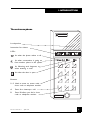
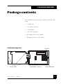
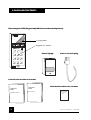
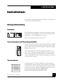
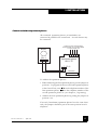
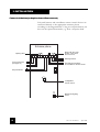
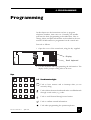
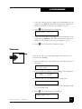
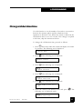
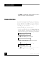
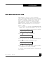
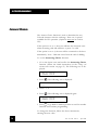
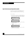
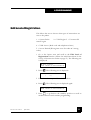
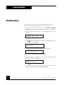
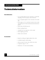
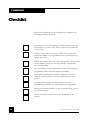
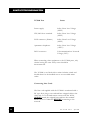
Telecode 5000 Installation manual Doc. No. 002 Issue 2 April 1998 1 Bewator, a part of Andersson and Bennet AB, develops and markets products and systems for access control, e.g. code locks, card readers and entrance phones. Sales, installation and servicing are handled by a nationwide dealer network. Copyright © August 1996 Bewator AB, Solna April 1997 Metric Security Ltd., UK Material from the Telecode Installation Manual may only be copied with the consent in writing of Bewator. Bewator reserves the right to alter both the content of the manual and the design of the product. Actions (such as unpermitted manipulation, copying etc) must not be taken with the software contained in the products and systems. Such actions are regarded as copywright violation and may result in imprisonment or fines and may likewise lead to an obligation to pay damages and compensation for using the software. 2 Doc. No. 002 Issue 2 April 1998 TABLEOFCONTENTS Document number: GBTC50000701 TableofContents 1Introduction ......................................................... 4 2Packagecontents ..................................................11 3Installation ..........................................................13 4Programming .......................................................19 5Telecodeincompanies ...........................................36 6Technicalinformation .............................................38 7Checklist ............................................................40 8UKStatutoryInformation .........................................41 Doc. No. 002 Issue 2 April 1998 3 1. INTRODUCTION Telecode entrance phones connected to the network Telecode 5000 is a system of entrance phones connected to the telephone network. The advantage with this type of system is that the door can be opened from a normal telephone all approved models using tone dialling can be used. Up to six entrance phones can be connected (one at each door). The central unit comes in different sizes with the capacity of 16 doors. The units also have different storage capacities for programming telephone numbers. In addition to the door phone function, Telecode 5000 works as a code lock, which means that people living in the building can gain access by entering a code number. Telecode 5000 can also be used in businesses where visitors are received after office hours. This is described in the Telecode in companies chapter later in this manual. Telecodeinapartmentbuildings If Telecode 5000 is installed in an apartment building, the system works as follows: Atthedoor Whenever a visitor wants to enter the door, they first use the entrance phone outside the door to speak to the tenant. To do this, the visitor should press B, followed by either the short code published on the name board next to the entrance phone, or the tenants phone number. The buttons of the entrance phone are described on page 9. The system also has "ultra-short" codes which apply to the first 10 stored numbers only. This means that instead of B0001, the caller can key A1; instead of B0002 use A2 and so on up to A9 instead of B0009. 4 Doc. No. 002 Issue 2 April 1998 1. INTRODUCTION If the line is busy If the apartment phone is in use, a busy tone is heard in the entrance phone. The call is then disconnected after five seconds. To avoid waiting, the system can be set so that the visitor can open the door by repeating the telephone number just dialled (see page 32). Accesscode Tenants, the postman and other authorised people are also allowed to enter the premises. In parallel with the entrance phone function, there is also a code lock function. Up to 99 unique access codes can be assigned for different doors. If the wrong access code is entered three times in succession, the code lock converts to sabotage mode and cannot be used. To set it into operation again the correct entrance code must be entered twice in succession. Intheapartment Since the entrance phone is connected to the telephone network the tenant uses his own telephone both to speak to visitors and to open the door. When a visitor dials the short code or the telephone number to the apartment, the telephone rings as usual. When the person in the apartment lifts the handset, depending on the Answer Choice set on the Telecode, either an electronic "tune" will be heard to show that the call is coming from the door or the tenant will be connected. If not immediately connected, the tenant presses 5. The tenant can now speak to the visitor for up to 45 seconds. Doc. No. 002 Issue 2 April 1998 5 1. INTRODUCTION Ifthetenantwantstoopenthedoor The door may be opened by dialling 5 on the tenants telephone. The door is opened for the lock activating time. Ifthetenantdoesnotwanttoopenthedoor If the tenant does not want to open the door, dial 0, then replace the handset. Forwarding If the tenants telephone is forwarded to another number, calls from the door are also forwarded to this number. The door can also be opened from this number, according to the instructions above. Selectthehourswhenaccesscodesandcallsareallowed Telecode has a built-in timer used to set the times when access codes, short codes and telephone numbers are valid. This way unwanted calls are prevented at night. The timer can also be used to keep the door unlocked at certain times, as required. 6 Doc. No. 002 Issue 2 April 1998 1. INTRODUCTION Tenantswithoutatelephone Tenants without a telephone can also use the system. A separate 4-core cable is wired to the apartment where a Bewator apartment phone is mounted. The apartment phone can only receive calls from the entrance phone. The entrance phone works as described earlier. If a call is made, intervals of three short tones are heard in the apartment phone. The call goes on for 60 seconds. If several apartment phones are connected in parallel, the call can be taken on any phone. A conversation can go on for 45 seconds. After 35 seconds a warning signal is heard. The tenant opens the door by pressing Open on the apartment phone, then replaces the handset. Telecodeandansweringmachines If an answering machine is connected to the number to call from the entrance phone, the announcement must be somewhat modified. Otherwise, the answering machine might open the door. Ensure that the "Open on Hang-up" is set OFF Announcement heard in the entrance phone: Check that the message is no longer than 45 seconds. Announcement not heard in the entrance phone: Record the tone signal for 0 (zero) before the actual message. To do this a telephone tone transmitter will be needed ( sold in most telephone shops). This is how to record the message: 1 Start the tape and wait 4 seconds. 2 Hold the tone transmitter against the microphone and press 0. 3 Record the message. Doc. No. 002 Issue 2 April 1998 7 1. INTRODUCTION Speakoneatatime During a call between the entrance phone and the telephone in the apartment, only one person can talk at a time. For the communicationen to work as smoothly as possible the participants should be aware of this. 8 Doc. No. 002 Issue 2 April 1998 1. INTRODUCTION The entrance phone BEWATOR Loudspeaker Instruction for visitors LEDs: B B Lit when the phone makes a call. Lit when conversation is going on from another phone in the system. Lit following each keypress, e.g. when entering a code. Lit when the door is open. Buttons: 09 Used to enter an access code, short code or telephone number. A Press A to interrupt a call. B Press B before you dial a short code or telephone number. Doc. No. 002 Issue 2 April 1998 1 2 3 4 5 6 7 8 9 A 0 B TELECODE 9 1. INTRODUCTION In the chapters listed below,the following are covered: Package contents does the package include all the parts needed to install and implement the entrance phone system? Installation instructions and wiring diagrams describing how to install the system. Programming step-by-step instructions on registering information in the system. Telecode in companies describes how the entrance phone system should be used in companies, e.g. if connected to a switchboard. Check list check that all steps have been completed in the installation and put a cross in the check boxes in the check list. Technical information list of information about power supply, memory capacity, dimensions etc. 10 Doc. No. 002 Issue 2 April 1998 2.PACKAGECONTENTS Package contents The standard Telecode package should contain the following: 1 central unit 16 entrance phones 1 transformer 1 line cord with plug this manual and a user manual information sheet for the tenants Central unit (opened) Screw holes Doc. No. 002 Issue 2 April 1998 Display Removable memory Small keyboard 11 2.PACKAGECONTENTS EntrancephoneTP5(KeypadonlyM65doesnothaveloudspeaker) BEWATOR Loudspeaker B Keypad for visitors 1 2 3 4 5 6 7 8 9 A 0 B PowerSupply Line cord with plug Installation and user manual Telecode 5000 Installation manual 12 Telecode 5000 User manual Information sheet for tenants Telecode 5000 Information to tenants Doc. No. 002 Issue 2 April 1998 3. INSTALLATION Installation This chapter contains illustrations and step-by-step instructions on how to install Telecode 5000. Placingandmounting Centralunit The central unit is designed for wall mounting (there are three screw holes in the back plate), in a secure room with normal temperature, e.g. the buildings power room. Place the transformer near the central unit. Theentrancephones(TP5)andkeypads(M65) Mount the entrance phones in the desired entrances at a height of 120 to 140 cm, from the ground to the bottom edge of the phone. Where provision for the disabled is required, a suitable height is about 95 cm. BEWATOR B 1 2 4 5 3 6 7 8 9 A 0 B The entrance phone is rated for temperatures between 35° and +55° C, and can be mounted indoors as well as outdoors. If the entrance phone is mounted outdoors, you should seal screw- and cable holes with a sealing compound (e.g. silicone), to prevent water leakage. Thenameboards Våning Kortnr Namn 1 B0001 Olsson 1 B0001 Jonsson 2 B0001 Persson 2 B0001 Karlsson 3 B0001 Nilsson 3 B0001 Bengtsson 4 B0001 Johansson 4 B0001 Eriksson Doc. No. 002 Issue 2 April 1998 If Nameboards are to be used, and place each board next to the appropriate entrance phone. The name board can either be screwed to the wall or fastened behind a glass window (if any) in the door leaf. The name board should contain the name of the tenant, short code and floor. Note! Do not forget to put a B in front of the short code. 13 3. INSTALLATION Apartmentphones If apartment phones are to be connected, they should be placed in a suitable place in the apartment (wall or table mounting). The apartment phones are connected to the central unit with a 4-core cable (4x0,5mm or equivalent). Instructions on how to address and connect the apartment phones are on page 17. Beforestartingtoinstallthesystem At the back of the user manual are four charts. Make copies of the charts and ask the system manager to fill them in according to the instructions in the Preparations chapter in the user manual. Also check that this person gets a copy of the user manual. Connecting-up To connect the different components in the entrance phone system proceed as follows: 1 Wire a 4-core cable between the central unit and each entrance phone*. Use a 2-core cable between the entrance phone and the electric release. This cable should be rated according to the current of the electric release. 2 Connect the transformer to the central unit (see the wiring diagram on page 16). 3 Connect the plug to the central unit (see the wiring diagram on page 16). * 14 On installation in environments with excessive electrical disturbances, a screened 4-core cable is adviseable to ensure the best sound quality. Doc. No. 002 Issue 2 April 1998 3. INSTALLATION 4 Push the plug into the telephone line socket. (If the socket is not yet installed, the entrance phone can still function as a code lock.) 5 Program time zones, access codes, short codes etc in the central unit (as described in the Programming chapter). Use the charts that have been filled in by the system manager. Now the system is installed and all the information it needs to operate has been programmed. To make sure everything has been done, complete the check list on page 36. Important:informtheusers! Do not forget to inform the users about the system and how it works. The small information sheet included in the Telecode 5000 package contains everything the users need to know to open the door, to not open the door, record announcements on the answering machine etc. In addition, it instructs visitors in how to make calls from the entrance. Fill in the current access code and ensure that the sheets are distributed to the users. Doc. No. 002 Issue 2 April 1998 15 3. INSTALLATION Wiringdiagrams Connectentrancephones,plugandtransformer The diagram below shows how to connect the entrance phone to the central unit and the lock, and where the transformer, plug and printer (if any) should be connected. Transformer Ground TC 5000 Central Unit PL 1 TelePhone Line Plug 1 2 3 4 5 Red White PL 2 1 2 3 4 5 6 7 8 TP5 Entrance Phone Connections or M65 Keypad No.1 for Remaining 4 1 2 3 4 5 6 7 8 TP5 Entrance Phone or M65 Keypad No.2 Doors Fail Safe Connection 1 Printer Connection 1 2 3 4 5 6 7 8 9 10 11 12 13 14 15 16 17 18 19 20 21 22 23 24 1 2 3 4 5 6DTR 6 2 PL 3 1 2 3 4 5 6 7 8 5 3 4 0 Volt Data Note! It is crucial that the central unit is grounded, since it has builtin lightning protection. This will not work unless the unit is grounded. 16 Doc. No. 002 Issue 2 April 1998 3. INSTALLATION Connectandaddressapartmentphones All connected apartment phones (10 maximium) are connected in parallel in the central unit. An extra buzzer may be connected. Connect to the corresponding terminal block no in terminal block 3 in the central unit Buzzer PL 1 SU–1 + – 4 3 2 1 Apartment phone V801–TC + 2 PL 2 1 Addresses 10 9 8 7 6 5 4 3 2 1 To address the apartment phones: 1 When addressing the first apartment phone, put the jumper on position 1. To program the short code for the apartment phone at the Central Unit, enter 1 as the telephone number of the first apartment phone, 2 as the telephone number of the second apartment phone etc (see chapter 4, Programming). 2 Address the next apartment phone by putting the jumper on position 2 etc. If several (3 maximum) apartment phones have the same short code, the jumpers should be put in the same position in each telephone. Doc. No. 002 Issue 2 April 1998 17 3. INSTALLATION Connectexitbutton(andoptionalsurveillancecamera) Exit push buttons and surveillance camera control devices are connected directly to the appropriate entrance phone according to the diagram below. Using an exit push button, the door can be opened from inside, e.g. from a reception desk. Entrance phone Opening relay 1 2 3 4 5 6 7 8 9 10 11 12 13 14 Drawn with the cover closed – open when the cover is off Sabotage switch To the central unit (see page 16) Terminal block numbers for surveillance camera control Exit push button - + Loudspeaker volume control OFF ON 18 Background lighting on/off Doc. No. 002 Issue 2 April 1998 4. PROGRAMMING Programming In this chapter are the instructions on how to program telephone numbers, time zones etc. Normally, the installer performs the basic programming,as described here. How to change, delete and print information are described in the user manual. All information is programmed on the central unit. Proceed as follows: 1 Open the cover of the central unit, using the key supplied. Display Small keyboard 2 Use the keyboard when programming the information. The display shows prompts telling what to do next. Keys 1 2 3 4 5 6 7 8 9 * 0 # Esc 09 Usedtoenterdigits. Esc Used to leave menues and to interrupt what you are currently doing. Used to delete characters backwards and to scroll backwards through stored entries, e.g. codes. Used to scroll forward through stored entries. Used to confirm entered information. Used when programming the apartment phones. Doc. No. 002 Issue 2 April 1998 19 4. PROGRAMMING In stand-by position, the following text is displayed: 94-11-17, TC5000 V0.00 17:15 Press Todays date and time are displayed. Press . The main menu is displayed: 1) CODES 3) DOORS 2) 4) TELE TIMES Choose what information to register, change or delete. If nothing is entered within two minutes, the central unit reverts to stand-by position. Note! Press Esc to cancel a programming sequence already started. Settimeanddate MAY 112 99 9 33 3 66 1 FRIDAY Use this function to set the time and date. When the system is delivered, time and date are already set, so normally there is no need to change this information. Adjustment to daylightsaving time is done automatically on the last Sunday in March and the last Sunday in October To change time and date, proceed as follows: 1 Display the main menu and choose TIMES (press 4). The following text is displayed: 1) TIME OF DAY 2) TIME ZONES 2 Press 1. The following text is displayed: ENTER TIME : 20 13:35 Doc. No. 002 Issue 2 April 1998 4.PROGRAMMING 3 Enter the current time by typing hours and minutes in one sequence, e.g. 0835 for thirty-five minutes past eight. If no change is to made to the time, go straight to step 4. 4 Press . The following text is displayed: ENTER DATE - 94-12-25 5 Enter the current date by entering year, month and day in one sequence, e.g. 941225 for the 25th of December 1994. If no change is to be made to the date, go straight to step 6. 6 Press . The main menu is displayed again. Timezones NewEntry Take out the Time zones chart and program the time zones to be used in the building. 1 Choose TIMES (4) on the main menu. The following text is displayed: 1) TIME OF DAY 2) TIME ZONES 2 Choose TIME ZONES (2). The following text is displayed: 1) NEW 2) EDIT 3) DELETE 4) PRINT 3 Choose NEW (1). The following text is displayed: ENTER TIME (ZONE 1) - 4 Enter between what hours the first time zone should be valid, e.g. from 0000-2359. 5 Press . The following text is displayed: ENTER VALID DAYS 0000-2359 ( Doc. No. 002 Issue 2 April 1998 ) 21 4.PROGRAMMING 6 Choose which days the time zone should be valid. 1=Monday, 2=Tuesday etc. If the time zone should be valid the whole week, press 1, 2, 3, 4, 5, 6, and 7. If it should only be valid Saturdays and Sundays, press 6 and 7. If the wrong digit is typed, press the same digit once more to delete it. 7 Press . The following text is displayed: ENTER TIME (ZONE 2) - 8 Enter the desired time interval and days for the next time zone, if more time zones are needed. Otherwise, press Esc . The main menu is displayed. Accesscodes Newentry Take out the Codes chart and program the access codes to be used in the entrances: 1 Choose CODES (Press 1). The following text is displayed: 1) NEW 2) EDIT 3) DELETE 4) PRINT 2 Choose NEW (1). The following text is displayed: ENTER NEW CODE 3 Enter a new four-digit code, e.g. 1111. 4 Press . The following text is displayed: WHICH DOORS? 1111 ( ) The entered code is automatically displayed bottom left. 222 Isssue Doc. No. 002 Issue 2 April 1998 4.PROGRAMMING 5 Enter in which doors the code should be valid. 1=the first door, 2=the second door etc. If the code should only be used in the doors numbered as 4 and 5, only press 4 and 5. If the wrong digit is typed, press the same digit again to delete it. 6 Press . The following text is displayed: ENTER TIME ZONES , , (00,00,00) 7 Enter during which time zones the code should be valid. The code can be valid under three time zones at the most, e.g. 01, 02 and 10. If no time zone at all is programmed, the code will not work. If the wrong digit is typed, press the correct one. Press and replace the digit with when finished. The following text is displayed: ENTER NEW CODE 8 If needed, program the next code in the same way. Otherwise, press Doc. No. 002 Issue 2 April 1998 Esc . The main menu is displayed. 23 4.PROGRAMMING Doors Newentry Program the information to apply for each door. 1 Display the main menu and choose DOORS (3). The following text is displayed: 1) EDIT 2) PRINT 2 Choose EDIT (1). The following text is displayed: WHICH DOOR? (1-6) 3 Enter the door to program the information for, e.g. 1 for the first door. The following text is displayed: OPENING TIME? (1-999) (7) 4 Enter the desired lock activating time or keep the preset time (7 seconds). 5 Press . The following text is displayed: TIME ZONE F. DAY OPEN? (0=DISABLED) (0) 6 Enter the number of the time zone when the door should be unlocked. If the door should be unlocked 24 hours, keep the preset setting (0). 7 Press . The following text is displayed: TIME ZONE FOR OPEN BUTTON (0=ALWAYS) (0) 8 Enter the number of the time zone when the push button on the inside should work. If the button should always work, keep the preset setting (0). 242 Isssue Doc. No. 002 Issue 2 April 1998 4.PROGRAMMING 9 Press . The following text is displayed: TIME ZONE FOR CALLING NO (0=ALWAYS) (0) 10 Enter the number of the time zone when short code can be used. If short code is allowed 24 hours, keep the preset setting (0). . The following text is displayed: 11 Press TIME ZONE FOR TEL (0=ALWAYS) (0) NO? 12 Enter the number of the time zone when regular phone numbers can be used. If they are allowed 24 hours, keep the preset setting (0). . The following text is displayed: 13 Press TIME ZONE FOR REGISTRATION? (0=ALWAYS) (0) 14 Enter the number of the time zone to control printing to the printer. If printing is to occur 24 hours, keep the preset setting (0). 13 Press . The following text is displayed: WHICH DOOR? (1-6) 14 Enter information about the next door in the same way. Press Esc to go back to the main menu. Shortcodesandtelephonenumbers Newentry Doc. No. 002 Issue 2 April 1998 Using this function the short codes and telephone numbers to be used at each door can be programmed. Each telephone number is tied to a short code published on a board in the entrance. 25 4.PROGRAMMING 1 Display the main menu and choose TELE (2). The following text is displayed: 1) NEW 2) EDIT 3) DELETE 4) PRINT 2 Choose NEW (1). The following text is displayed: ENTER TELE NO (0001) 3 Enter the telephone number to be tied to the short code B0001. If the central unit is connected as an extension in a private branch exchange (See Answering Choice, see page 30) enter the direct dial extension number. 4 Press . The following text is displayed: WHICH DOORS? ( ) 5 Enter in which door/s the telephone number/short code should be used. 6 Press . The following text is displayed: ENTER TELE NO (0002) 7 Program the next telephone number in the same way. Note! If you are going to program a short code for an apartment phone, enter 1 (corresponds to a telephone number) for the first apartment phone, 2 for the second apartment phone etc. Press Esc when finished. The main menu is displayed. Now the information that the system needs to operate has been programmed. If any information needs to be edited or deleted, read the user manual where these functions are described. 262 Isssue Doc. No. 002 Issue 2 April 1998 4.PROGRAMMING Changecalldurationtime Use this function to set the number of seconds a conversation between the entrance phone and the telephone in the apartment is allowed to last. When the system is delivered, the call duration time is set to 45 seconds. If no change is required at this time, skip the instructions below. To change the call duration time, proceed as follows: 1 Press Esc three times when the central unit display is in standby position. The following text is displayed: OPTIONS MENU 2 Press / 3 Press . The following text is displayed: TO SCROLL . The following text is displayed: / TO SCROLL CHANGE PASSWORD 4 Press . The following text is displayed: / TO SCROLL CHANGE TALK TIME 5 Press . The following text is displayed: ENTER TIME (1–999 sec) (45) 6 Enter the desired call duration time and press following text is displayed again: . The / TO SCROLL CHANGE TALK TIME Doc. No. 002 Issue 2 April 1998 27 4.PROGRAMMING 7 Press Esc to go back to the stand-by position or scroll to another function and continue programming. Changecallingtime Use this function to change the calling time, i.e. for how long the entrance phone should attempt to contact the telephone before the call is disconnected. When the system is delivered, the calling time is set to 30 seconds. If no change is required to the calling time, skip this section. To change the calling time, proceed as follows: 1 Go to the Options menu and scroll to the Change calling time function (follow the initial instructions in the Change call duration time section on page 27). The following text is displayed: / TO SCROLL CHANGE CALLING TIME 2 Press .. . The . following text is displayed: ENTER TIME (1–999 sec) (30) 3 Enter the desired calling time, e.g. 25 for 25 seconds. 4 Press . The following text is displayed again: / TO SCROLL CHANGE CALLING TIME 5 Press Esc to go back to the stand-by position or scroll to another function and continue programming. 282 Isssue Doc. No. 002 Issue 2 April 1998 4.PROGRAMMING User-definedshortcodeson/off When the system is delivered, the system automatically suggests a short code (starting with 0001) when programming new telephone numbers. This means the User-defined short codes function is switched off. If needed, it can be switched on. When the function is switched on an additional prompt is displayed when new telephone numbers are programmed (see page 26). The prompt asks which short code is to be used. Proceed as follows: 1 Go to the Options menu and scroll to the User def. short code function (follow the initial instructions in the Change call duration time section on page 27). The following text is displayed: / TO SCROLL ENABLE QUICK NO PROG 2 Press . The following text is displayed: ENTER 1 (ON) / 0 (OFF) (0) 3 Press 1 (this switches on the User def. short code function). 4 Press . The following text is displayed again: / TO SCROLL ENABLE QUICK NO PROG 5 Press Esc to go back to the stand-by position or scroll to another function and continue programming. To switch the function off, follow the above instructions, only enter 0 in step 3. Doc. No. 002 Issue 2 April 1998 29 4.PROGRAMMING AnswerChoice The Answer Choice function is used to determine the way Telecode interacts with the exchange. There are 2 options available for UK operation. (Option 0 must not be used in UK) If the option is set to 1, the users will hear the electronic tune when answering calls and will have to press 5 to talk If the option is set to 2, the user will be connected to the door immediately. Note:- Talk time starts from the end of dialling. To set the Answering Choice function: 1 Go to the Options menu and scroll to the Answering Choice function (follow the initial instructions in the Change call duration time section on page 27). The following text is displayed: / TO SCROLL ANSWER CHOICE 2 Press . The following text is displayed: ENTER 1 (ON) / 0 (OFF) (0) 3 Press 1 or 2. 4 Press . The following text is displayed again: / TO SCROLL ANSWER CHOICE 5 Press Esc to go back to stand-by position or scroll to another function and continue programming. To change the function, follow the above instructions, entering the new value. 302 Isssue Doc. No. 002 Issue 2 April 1998 4.PROGRAMMING Openthedooronhang-upon/off Normally, the unit is set so that the entrance door is only opened when the tenant dials 5 on his telephone dialpad. The effect of this setting is that the door is also opened on hang-up or time-out. N.B. THIS FUNCTION MUST NOT BE USED WITH ANSWER CHOICE 2. Proceed as follows: 1 Go to the Options menu and browse to the Open on hang-up function (follow the initial instructions in the Change call duration time section on page 27). The following text is displayed: / TO SCROLL OPEN ON HANG-UP 2 Press . The following text is displayed: ENTER 1 (ON) / 0 (OFF) (1) 3 Press 1 (means that the door is opened when the tenant replaces the handset). 4 Press . The following text is displayed again: / TO SCROLL OPEN ON HANG-UP 5 Press Esc to go back to the stand-by position or browse to another function and continue programming. Doc. No. 002 Issue 2 April 1998 31 4.PROGRAMMING Openthedoorbyrepeatingnumber(on/off) This function can switch off the setting allowing the visitor to open to door by repeating the telephone number when the telephone in the apartment is busy. This is the default setting . Proceed as follows: 1 Go to the Options menu and browse to the Open on busy tone function (follow the initial instructions in the Change call duration time section on page 27). The following text is displayed: / TO SCROLL OPEN ON 2nd BUSY TONE 2 Press . The following text is displayed: ENTER 1 (ON) / 0 (OFF) (1) 3 Press 0 (means that the door cannot be opened by repeating the number just entered). 4 Press . The following text is displayed: / TO SCROLL OPEN ON 2nd BUSY TONE 5 Press Esc to go back to stand-by position or browse to another function and continue programming. 322 Isssue Doc. No. 002 Issue 2 April 1998 4.PROGRAMMING EditLevelofRegistration This allows the user to choose what types of transactions are sent to the printer 1 = System Faults remote logins 2 = Valid Logins 3 = Unsuccessful 4 = Valid Access (Both code and telephone release) 5 = Access Denied (Wrong time zone for codes & 3 wrong codes) 1 Go to the Options menu and scroll to the Edit Level of Registration function (follow the initial instructions in the Change call duration time section on page 27). The following text is displayed: / TO SCROLL EDIT LEVEL OF REGISTRATION 2 Press . The following text is displayed: ENTER LEVELS ( 4 ) 3 Enter the values required from the list above 4 Press . The following text is displayed again: / TO SCROLL EDIT LEVEL OF REGISTRATION 5 Press Esc to go back to the stand-by position or scroll to another function and continue programming. Doc. No. 002 Issue 2 April 1998 33 4.PROGRAMMING PrintEventLog This allows the user to print transactions that have been stored in system when the printer is not connected 1 Go to the Options menu and scroll to the PRINT EVENT LOG function (follow the initial instructions in the Change call duration time section on page 27). The following text is displayed: / TO SCROLL PRINT EVENT LOG 3 Press . The following text is displayed if the printer is not connected or not on-line: THE PRINTER IS NOT READY YET The following text is displayed if the printer is ready PRINTING PRINT EVENT LOG Printing can be terminated by pressing Esc 4 When printing is complete, or has been terminated, the following text is displayed again: / TO SCROLL PRINT EVENT LOG 5 Press Esc to go back to the stand-by position or scroll to another function and continue programming. 342 Isssue Doc. No. 002 Issue 2 April 1998 4.PROGRAMMING Otheroptions Scrolling past the Open on busy tone function will give the Other options menu. These are functions designed for changing the internal parameters. There are no installer options here. If is pressed when the Other options menu is displayed, the following text is displayed: ENTER PARAMETER, VALUE , Press Doc. No. 002 Issue 2 April 1998 Esc twice to get back to stand-by position. 35 5.TELECODEINCOMPANIES Telecodeincompanies Telecode is an excellent alternative in businesses where visitors are received after office hours. By using the night service option in the exchange, several telephones with direct numbers can receive calls. Since Telecode is connected to the telephone network, the entrance phone and the telephone answering the calls can be located in different buildings, even in different parts of the country. Severalcompaniesinthesamebuilding Different companies, each with their own telephone exchange, but located in the same building can share a Telecode subscription. The entrance phone calls the exchange of the of the desired company. Used this way it is important to be able to open the door quickly, i.e. use telephones with tone dialling. This is how to check if tone dialling works: 1 Connect a regular telephone to the extension to be used by Telecode. Then call the phone/s to be used for door opening. 2 When you get an answer in this telephone, ask the person at the other end to press 5. A tone should be heard. Companiesusingswitchboards In companies where a switchboard is used, a tone transmitter is sometimes needed to produce an opening signal. 362 Isssue Doc. No. 002 Issue 2 April 1998 5.TELECODEINCOMPANIES Up to 10 direct Bewator telephones can be connected to Telecode. This will avoid telephone charges and a possible opening delay. Up to three entrance phones can be connected in parallel, so can call the same number. Since companies often receive several visitors during office hours, Telecode should be programmed so that the line is open for visitors and not for outgoing calls. Doc. No. 002 Issue 2 April 1998 37 6.TECHNICALINFORMATION Technicalinformation Generalinformation Up to 6 entrance phones can be connected to a central unit, depending on the size (capacity) of the central unit Up to 10 apartment phones can be connected to the central unit Power supply: 24 V AC transformer connected to the central unit supplies power to both central unit and connected entrance phones Built-in timer with back-up power Remote opening function Adjustable lock activating time (1999 seconds) Built-in lightning protection Printer can be connected Thecentralunit Requires an analog (not digital) telephone line socket Lockable housing for wall mounting Memory capacity: 99 time zones and 99 access codes Temperature range: 0° to 50° Dimensions: 155 x 222 x 60 mm (HxWxD) 382 Isssue Doc. No. 002 Issue 2 April 1998 6.TECHNICALINFORMATION Entrancephones Impact resistant cast housing with stainless steel buttons Background lighting (can be switched off) Temperature range: 35° to 50° Dimensions: 200 x 80 x 30 mm (HxWxD) Doc. No. 002 Issue 2 April 1998 39 7.CHECKLIST Checklist Before the installation can be considered as completed, the following should be checked: that the line socket works (plug a standard telephone into the socket and try to make a call). Then connect the central unit to the socket. that the correct time zones, access codes, short codes and telephone numbers are programmed in the central unit according to the charts. that the door opens when you enter a programmed access code on the entrance phone (do not forget that the current time zone must be valid). that the telephones in the apartments can be called using the programmed short codes and telephone numbers. that verbal communication with the telephones functions correctly, and that the door can be opened from the telephones. that the system manager has been trained in system programming and knows what information is programmed. that the user manual and keys to the system has been given to the system manager. that the information sheets have been distributed to the tenants. 402 Isssue Doc. No. 002 Issue 2 April 1998 8.UKSTATUTORYINFORMATION Approval Number The Telecode TC5000 system (TC5000) has been approved for connection to telecommunications systems specified in these instructions for use and subject to the conditions set out in them. The approval number is 503935. Approval type The TC5000 has been approved to NTR3 for use with direct exchange lines and compatible PABXs. B.T. Circuits The apparatus is approved for connection to the Public Switched Telephone Network provided by British Telecommunications plc, Kingston-upon-Hull City Council and Mercury Communications Ltd. REN REN ( Ringer Equivalence Number ) is a value given to all apparatus which can be connected to the PSTN. The REN is used to calculate the number of pieces of apparatus which may be connected simultaneously to a single PSTN line, without impairing the performance of the standard bell circuit. The RENs of all simultaneously connected apparatus should not exceed 4.0 on any single PSTN line. The TC5000 has a REN of 1.0 Doc. No. 002 Issue 2 April 1998 41 8.UKSTATUTORYINFORMATION Manufacturer The TC5000 is supplied in the UK by Bewator Division of Metric Security Ltd. Functions The TC5000 has the following functions: · Automatic dialing of a stored number · Loop disconnect signalling · Multi-frequency signalling · Automatic answer Auto-calling In order to minimize the risk of inconvenience to other network subscribers, users are advised to carefully check all numbers entered during the set-up of stored numbers prior to dialing. Where to connect the TC5000 The TC5000 may only be connected to the following installations · 422 Isssue Direct Exchange Lines ( D.E.L.s ) with loop disconnect and /or multi-frequency signaling i.e. a line directly connected to a telephone exchange with its own exchange numbers. Doc. No. 002 Issue 2 April 1998 8.UKSTATUTORYINFORMATION · Extensions via sockets provided for D.E.L.s · Extensions for compatible PABXs. NOTE: It is not possible to guarantee correct operation under all possible conditions on all approved compatible PABXs. Where not to connect the TC5000 · To a shared line ( Party Line ) · As an extension to a payphone · to a 1+1 carrier system Any other usage will invalidate the approval of the apparatus if as a result it then ceases to conform to the standards against which approval was granted. Connection of power supply The TC5000 is intended for use when powered by a Tufvassons 6024-0130 24V AC power supply. Other usage will invalidate the approval given to this apparatus if as a result it ceases to comply with EN41003. Connection and Interconnection of ports Safety Statement In compliance with European Safety Standard EN41003, the safety status of the ports intended for the interconnection of other equipment are as follows; Doc. No. 002 Issue 2 April 1998 43 8.UKSTATUTORYINFORMATION TC5000 Port Status Power supply Safety Extra Low Voltage (SELV) TP5/M65 door terminals Safety Extra Low Voltage (SELV) DTE connector ( Printer ) Safety Extra Low Voltage (SELV) Apartment telephones Safety Extra Low Voltage ( SELV) PSTN connector Telecommunications Network Voltage (TNV) When connecting other equipment to the TC5000 ports, only circuits having the same safety status should be interconnected. The TC5000 is not fitted with a mains isolation switch and should there fore be installed near to an accessible mains outlet. Connecting Line Cords The line cord supplied with the TC5000 is terminated with a BT type 431A plug at one end and bare stripped cable at the other end. To avoid inadvertent contact with the PSTN, ALWAYS attach the stripped bare end into the terminal blocks on the TC5000 first BEFORE connecting to the network. 442 Isssue Doc. No. 002 Issue 2 April 1998 Bewator Group Ltd, Albany Street, Newport, South Wales NP20 5XW Tel: +44 (0)1633 821000 Fax +44 (0)1633 850893 E-mail:- [email protected]


![[UK] Saver NG Data Sheets A1-2013](http://vs1.manualzilla.com/store/data/005759312_1-088a9b2c9a495b4ddfffe35115070dd1-150x150.png)