1
EML 4905 Senior Design Project
A B.S.M.E THESIS
PREPARED IN PARTIAL FULFILLMENT OF THE
REQUIREMENT FOR THE DEGREE OF
BACHELOR OF SCIENCE
IN
MECHANICAL ENGINEERING
URSA MATE ROV
Final Report
Nikko Miniello
Joshua Gonzalez
Brandon O’Neill
Advisor: Sabri Tosunoglu, Ph.D.
April 10, 2015
This B.S. thesis is written in partial fulfillment of the requirements in EML 4905.
The contents represent the opinion of the authors and not the Department of
Mechanical and Materials Engineering.
Ethics Statement and Signatures
The work submitted in this B.S. thesis is solely prepared by a team consisting of Nikko Miniello,
Joshua Gonzalez, and Brandon O’Neill and it is original. Excerpts from others’ work have been
clearly identified, their work acknowledged within the text and listed in the list of references. All
of the engineering drawings, computer programs, formulations, design work, prototype
development and testing reported in this document are also original and prepared by the same
team of students.
Nikko Miniello
Joshua Gonzalez
Brandon O’Neill
Team Leader
Team Member
Team Member
Dr. Sabri Tosunoglu, Ph.D.
Faculty Advisor
ii
Table of Contents
Ethics Statement and Signatures ................................................................................................................... ii
Table of Contents ......................................................................................................................................... iii
Table of Figures ........................................................................................................................................... vi
List of Tables ................................................................................................................................................ x
1.
2.
3.
4.
Introduction ........................................................................................................................................... 1
1.1
Problem Statement ........................................................................................................................ 1
1.2
Motivation ..................................................................................................................................... 2
1.3
Literature Survey .......................................................................................................................... 3
1.4
Survey of Related Standards ......................................................................................................... 8
1.5
Discussion ................................................................................................................................... 11
Project Formulation ............................................................................................................................ 12
2.1
Overview ..................................................................................................................................... 12
2.2
Project Objectives ....................................................................................................................... 12
2.3
Design Specifications.................................................................................................................. 12
2.4
Addressing Global Design .......................................................................................................... 13
2.5
Constraints and Other Considerations......................................................................................... 13
Design Alternatives ............................................................................................................................. 14
3.1
Overview of Conceptual Designs Developed ............................................................................. 14
3.2
Design Alternate 1 ...................................................................................................................... 15
3.3
Design Alternate 2 ...................................................................................................................... 16
3.4
Design Alternate 3 ...................................................................................................................... 17
3.5
Integration of Global Design Elements ....................................................................................... 18
3.6
Feasibility Assessment ................................................................................................................ 18
3.7
Proposed Design ......................................................................................................................... 19
3.8
Discussion ................................................................................................................................... 20
Project Management ........................................................................................................................... 21
4.1
Overview ..................................................................................................................................... 21
4.2
Breakdown of Work into Specific Tasks .................................................................................... 21
4.3
Gantt Chart for the Organization of Work and Timeline ............................................................ 21
4.4
Breakdown of Responsibilities among Team Members ............................................................. 22
4.5
Commercialization of the Final Product ..................................................................................... 22
4.6
Discussion ................................................................................................................................... 22
iii
5.
6.
7.
8.
Engineering Design and Analysis ....................................................................................................... 23
5.1
Overview ..................................................................................................................................... 23
5.2
Kinematic Analysis ..................................................................................................................... 24
5.3
Dynamic/ Vibration Analysis of the System ............................................................................... 31
5.4
Structural Design ........................................................................................................................ 33
5.5
Force Analysis ............................................................................................................................ 37
5.6
Stress Analysis ............................................................................................................................ 40
5.7
Material Selection ....................................................................................................................... 42
5.8
Design Based on Static and Fatigue Failure Design Theories .................................................... 43
5.9
Deflection Analysis ..................................................................................................................... 45
5.10
Component Design/ Selection ..................................................................................................... 47
5.11
Finite Element Analysis .............................................................................................................. 51
5.12
Design Overview ........................................................................................................................ 52
5.14
Cost Analysis .............................................................................................................................. 53
5.15
Discussion ................................................................................................................................... 55
Prototype Construction ....................................................................................................................... 56
6.1
Overview ..................................................................................................................................... 56
6.2
Description of Prototype ............................................................................................................. 56
6.3
Prototype Design ......................................................................................................................... 56
6.4
Parts List ..................................................................................................................................... 59
6.5
Construction ................................................................................................................................ 61
6.6
Prototype Cost Analysis .............................................................................................................. 62
6.7
Discussion ................................................................................................................................... 62
Testing and Evaluation........................................................................................................................ 63
7.1
Overview ..................................................................................................................................... 63
7.2
Design of Experiments – Description of Experiments ................................................................ 63
7.3
Test Results and Data.................................................................................................................. 64
7.4
Evaluation of Experimental Results ............................................................................................ 70
7.5
Improvement of the Design......................................................................................................... 71
7.6
Discussion ................................................................................................................................... 72
Design Considerations ........................................................................................................................ 73
8.1
Assembly and Disassembly ........................................................................................................ 73
8.2
Maintenance of the System ......................................................................................................... 73
iv
8.2.1
Regular and Major Maintenance ......................................................................................... 73
8.3
Environmental Impact ................................................................................................................. 73
8.4
Risk Assessment ......................................................................................................................... 74
9.
Design Experience .............................................................................................................................. 75
9.1
Overview ..................................................................................................................................... 75
9.2
Standards Used in the Project ..................................................................................................... 75
9.3
Contemporary Issues ................................................................................................................... 76
9.4
Impact of Design in a Global and Societal Context .................................................................... 76
9.5
Professional and Ethical Responsibility ...................................................................................... 77
9.6
Life-Long Learning Experience .................................................................................................. 77
9.7
Discussion ................................................................................................................................... 77
10.
Conclusion ...................................................................................................................................... 78
10.1
Conclusion and Discussion ......................................................................................................... 78
10.2
Evaluation of Integrated Global Design Aspects ........................................................................ 79
10.3
Evaluation of Intangible Experiences ......................................................................................... 79
10.4
Commercialization Prospects of the Product .............................................................................. 80
10.5
Future work ................................................................................................................................. 81
References ................................................................................................................................................... 82
Appendix ..................................................................................................................................................... 83
Appendix A: Detailed Engineering Drawing of all Parts........................................................................ 83
Appendix B. Multilingual User’s Manuals (in English, Spanish, and Italian)........................................ 97
Appendix C. Detailed Raw Design Calculations and Analysis (Scanned Material) ............................. 107
Appendix D. Copies of Used Commercial Machine Element Catalogs (Scanned Material) ................ 108
Product Description ....................................................................................................................... 117
Appendix E. Project Photo Album........................................................................................................ 123
Appendix F. Code ................................................................................................................................. 127
v
Table of Figures
Figure 1 - Literature Survey, ROV 2.6 [OpenROV | Underwater Exploration Robots] ............................... 5
Figure 2 - Literature Survey, IP Explanation ................................................................................................ 9
Figure 3 - Literature Survey, Guide to Ingress Protection Rating .............................................................. 10
Figure 4 - Conceptual Design, 1 ................................................................................................................. 15
Figure 5 - Conceptual Design 2 .................................................................................................................. 16
Figure 6 - Conceptual Design, 3 ................................................................................................................. 17
Figure 7 - Conceptual Design, 3 Simulated Model ..................................................................................... 17
Figure 8 - Proposed Design (Rough without Floats) .................................................................................. 19
Figure 9 - Proposed Design (Rendered) ...................................................................................................... 19
Figure 10 - Proposed Design (Actual) ........................................................................................................ 19
Figure 11 - Flow Analysis, URSA Trajectory Vectors ............................................................................... 24
Figure 12 - Flow Analysis, Trajectory Cut Plot .......................................................................................... 25
Figure 13 - Flow Analysis, 3D Isosurface Flow ......................................................................................... 25
Figure 14 - Flow Analysis, Rendered Assembled Front Section ................................................................ 28
Figure 15 - Flow Analysis, Assembled Isosurface...................................................................................... 29
Figure 16 - Flow Analysis, Cut Plot Side View .......................................................................................... 30
Figure 17 - Flow Analysis, Cut Plot Top View .......................................................................................... 30
Figure 18 - Structural, Rendered PVC Frame ............................................................................................. 33
Figure 19 - Structural, Wire Entry Simulation (Top View) ........................................................................ 35
Figure 20 - Structural, Wire Entry Simulation (Top View - Sectional) ...................................................... 35
Figure 21 - Structural, Wire Entry Simulation (Close up - Sectional) ........................................................ 35
Figure 22 - Structural, Wire Entry .............................................................................................................. 36
Figure 23 - Structural, Wire Entry (Angled View) ..................................................................................... 36
Figure 24 - Simulation, Model Information ................................................................................................ 37
Figure 25 - Simulation, Stress Analysis ...................................................................................................... 40
Figure 26 - Simulation, Strain Analysis ...................................................................................................... 41
Figure 27 - Simulation, Factor of Safety Analysis...................................................................................... 43
Figure 28 - Simulation, Deflection Analysis .............................................................................................. 45
Figure 29 - Component, Xbox 360 Control ................................................................................................ 47
Figure 30 - Component, Xbox 360 Wireless Receiver ............................................................................... 47
Figure 31 - Component, Robotic Claw - MKII ........................................................................................... 47
Figure 32 - Component, Robotic Claw Pan/Tilt Bracket - MKII ............................................................... 47
Figure 33 - Component, Arduino UNO ...................................................................................................... 47
Figure 34 - Component, GoPro Hero 3 ....................................................................................................... 47
Figure 35 - Component, HobbyKing Donkey ST3508 730KV Brushless DC Motor ................................ 48
Figure 36 - Component, Octura X470 1.4 Dia. Beryllium Copper Propeller ............................................ 48
Figure 37 - Component, HS-5086WP Metal Gear, Micro Digital Waterproof Servo ................................ 48
Figure 38 - Component, HS-5086WP Metal Gear, Micro Digital Waterproof Servo ................................ 48
Figure 39 - Component, HobbyKing Brushless Car ESC 100A ................................................................. 48
Figure 40 - Component, Astra Depot Aluminum High Powered 6W 6000k Xenon White LED ............... 48
Figure 41 - Component, Loctite Threadlocker blue 242 ............................................................................. 49
Figure 42 - Component, 3M™ Marine Adhesive Sealant 5200 Fast Cure ................................................. 49
vi
Figure 43 - Component, JB Weld WaterWeld Epoxy Putty ....................................................................... 49
Figure 44 - Component, Scotch Outdoor Mounting Tape .......................................................................... 49
Figure 45 - BenzOMatic Solder Core Rosin ............................................................................................... 49
Figure 46 - Component, Assorted Shrink Wrap ......................................................................................... 49
Figure 47 - Everbilt Flat Bar Aluminum ..................................................................................................... 50
Figure 48 - Component, Hex Bolt (1/4 in x 1-1/2 in) ................................................................................. 50
Figure 49 - Component, Everbilt Zinc Machine Screws Round Head Combo #8-32x1-1/2 inch .............. 50
Figure 50 - Component, Everbilt Zinc Machine Screws Round Head Combo #8-32x1-3/4 inch .............. 50
Figure 51 – Component, Southwire Landscape Wire ................................................................................. 50
Figure 52 - Component, Cerrowire Appliance Wiring ............................................................................... 50
Figure 53 - Simulation, Mesh ..................................................................................................................... 51
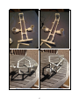
Figure 54 - Prototype 01 View 01............................................................................................................... 57
Figure 55 - Prototype 01 View 02............................................................................................................... 57
Figure 56 - Prototype 02 View 01............................................................................................................... 57
Figure 57 - Prototype 02 view 02................................................................................................................ 57
Figure 58 - Prototype Frame with Loose Housing ...................................................................................... 58
Figure 59 - Prototype Painted Frame .......................................................................................................... 58
Figure 60 - Prototype Aluminum Mounting Bars ....................................................................................... 58
Figure 61 - Prototype Motor Mounted ........................................................................................................ 58
Figure 62 - Testing Results, Testing Divebox 1 ......................................................................................... 66
Figure 63 - Testing Results, Testing Divebox 2 ......................................................................................... 66
vii
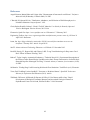
A 1 - Drawing Diagram, Motors ................................................................................................................. 83
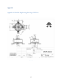
A 2 - Drawing Diagram, LED Lighting ...................................................................................................... 84
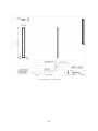
A 3 - Drawing Diagram, Simplistic Claw ................................................................................................... 85
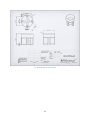
A 4 - Drawing Diagram, Motor Shroud ...................................................................................................... 86
A 5 - Drawing Diagram, Claw Mount ........................................................................................................ 87
A 6 - Drawing Diagram, Motor Mount ....................................................................................................... 88
A 7 - Drawing Diagram, Propeller .............................................................................................................. 89
A 8 - Drawing Diagram, URSA Frame....................................................................................................... 90
A 9 - Drawing Diagram, Wire Entry Tube ................................................................................................. 91
A 10 - Assembly Diagram, Wire Entry....................................................................................................... 92
A 11 - Assembly Diagram, URSA .............................................................................................................. 93
A 12 - Drawing, Robotic Claw MKII (SparkFun) ...................................................................................... 94
A 13 - Assembly Diagram, Robotic Claw MKII (SparkFun) ..................................................................... 95
A 14 - Assembly Diagram, Robotic Claw Pan/ Tilt Bracket – MKII (SparkFun) ...................................... 96
B 1 - User Manual, English 1...................................................................................................................... 97
B 2 - User Manual, English 2...................................................................................................................... 98
B 3 - User Manual, Italian 1........................................................................................................................ 99
B 4 - User Manual, Italian 2...................................................................................................................... 100
B 5 - User Manual, Spanish 1 ................................................................................................................... 101
B 6 - User Manual, Spanish 2 ................................................................................................................... 102
B 7 - User Manual, Turkish 1 ................................................................................................................... 103
B 8 - User Manual, Turkish 2 ................................................................................................................... 104
B 9 - User Manual, Persian 1 .................................................................................................................... 105
B 10 - User Manual, Persian 2 .................................................................................................................. 106
C 1 - Scanned Equations ........................................................................................................................... 107
D 1 - Scanned Catalog, Ranger ................................................................................................................. 108
D 2 - Scanned Catalog, ESC Specs [HobbyKing® ™ Brushless Car ESC 100A] ................................... 109
D 3 - Scanned Catalog, Servo Specs [HS-5646WP High Voltage, High Torque, Programmable Digital
Waterproof] ............................................................................................................................................... 110
D 4 - Scanned Catalog, Servo Specs [HS-5086WP Metal Gear, Micro Digital Waterproof Servo] ........ 111
D 5 - Scanned Catalog, Camera Specs [GoPro Hero 3] ............................................................................ 116
D 6 - Scanned Catalog, LED Specs [Astra Depot] ................................................................................... 117
D 7 - Scanned Catalog, Motor Specs [HobbyKing Donkey ST3508-730kv Brushless Motor] ................ 118
D 8 - Scanned Catalog, 3M™ Marine Adhesive Sealant 5200 Fast Cure White...................................... 120
D 9 - Scanned Catalog, JB Weld WATERWELD EPOXY PUTTY ........................................................ 121
D 10 - Scanned Catalog, Scotch Outdoor Mounting Tape........................................................................ 122
viii
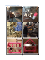
E 1 - Photo Album, Cutting PVC.............................................................................................................. 123
E 2 - Photo Album, Spraying PVC ........................................................................................................... 123
E 3 - Photo Album, Drilling Aluminum Mounting Bars .......................................................................... 123
E 4 - Photo Album, Drilling Aluminum Mounting Bars 2 ....................................................................... 123
E 5 - Photo Album, Partial Assembly Rear View ..................................................................................... 123
E 6 - Photo Album, Partial Assembly Top View ...................................................................................... 123
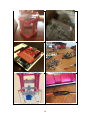
E 7 - Photo Album, Partial Assembly Front View .................................................................................... 124
E 8 - Photo Album, MKII Claw in Box .................................................................................................... 124
E 9 - Photo Album, Arduino Setup ........................................................................................................... 124
E 10 - Photo Album, Electronic Layout .................................................................................................... 124
E 11 - Photo Album, Mounted Claw......................................................................................................... 124
E 12 - Photo Album, Heat Shrunk Wires .................................................................................................. 124
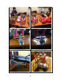
E 13 - Photo Album, Final Electronic Testing 1 ....................................................................................... 125
E 14 - Photo Album, Final Electronic Testing 2 ....................................................................................... 125
E 15 - Photo Album, LED off ................................................................................................................... 125
E 16 - Photo Album, LED on.................................................................................................................... 125
E 17 - Photo Album, Claw Holding Object .............................................................................................. 125
E 18 - Photo Album, Wire Box before Mounting ..................................................................................... 125
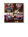
E 19 - Photo Album, Wire Box after Mounting ........................................................................................ 126
E 20 - Photo Album, Assembled (Front Top View) ................................................................................. 126
E 21 - Photo Album, Assembled (Rear View) .......................................................................................... 126
E 22 - Photo Album, Assembled (Angled View)...................................................................................... 126
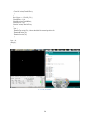
F 1 - Code, Screenshot .............................................................................................................................. 129
Equation 1 - Drag Force .............................................................................................................................. 28
Equation 2 - Resistance of a Wire ............................................................................................................... 64
Equation 3 - Voltage Loss........................................................................................................................... 65
Equation 4 - RPM ....................................................................................................................................... 68
Equation 5 - Horse Power ........................................................................................................................... 68
Equation 6 - Speed of Propeller .................................................................................................................. 69
ix
List of Tables
Table 1 - Gantt chart ................................................................................................................................... 21
Table 2 - Responsibility Breakdown ........................................................................................................... 22
Table 3 - Flow Analysis, Ambient Conditions ........................................................................................... 26
Table 4 - Flow Analysis, Goals................................................................................................................... 26
Table 5 - Flow Analysis, Min/ Max Values SI ........................................................................................... 27
Table 6 - Flow Analysis, Min/ Max Values English ................................................................................... 27
Table 7 - Loads and Fixtures ...................................................................................................................... 38
Table 8 - Stress Table ................................................................................................................................. 40
Table 9 - Strain Table ................................................................................................................................. 41
Table 10 - Volumetric Properties ................................................................................................................ 42
Table 11 - Material Properties .................................................................................................................... 42
Table 12 - Factor of Safety Table ............................................................................................................... 43
Table 13 - Deflection Table ........................................................................................................................ 45
Table 14 - Cost Analysis ............................................................................................................................. 53
Table 15 - Part List ..................................................................................................................................... 59
Table 16 - Test Results, Wire Resistance ................................................................................................... 64
Table 17 - Test Results, Voltage Loss ........................................................................................................ 65
Table 18 - Test Results, Buoyancy ............................................................................................................. 66
Table 19 - Testing Results, Propeller .......................................................................................................... 69
x
1. Introduction
1.1
Problem Statement
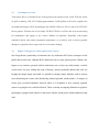
With the ever increasing demand for petroleum-based products, reaching further and digging
deeper have never been more in need. From maintaining undersea pipelines to conducting
experimental science underneath ice and around hot gas vents, there is a specific place for the
remote operated vehicle. A major challenge today is keeping people and equipment safe while
still being able to conduct required inspections and experimentation. Our aim is to construct a
prototype, remotely operated vehicle for use in maintenance and inspection of underwater
pipelines; one which has the dual functionality to conduct biological research in icy water
conditions.
The M.A.T.E. ROV competition permits a specific framework and rule set with added
constraints that will challenge our engineering abilities. With the intention to compete in the
Ranger class, we will construct a frame for the ROV, engineer and develop a control system, and
test and modify specific instruments used for manipulation and movement of the robotic arm that
will be located on the ROV.
Furthering this, we will look to past examples for a basis in technology that is optimal for these
conditions. Additionally, examining past designs will also provide us with key insights into what
designs and specifications are undesired. From this foundation we will use our own
developments and ideas together with proven parts to engineer and construct our vision of what
the ROV of the future will be.
1
1.2
Motivation
Navigating in deep, icy waters more often than not is quite treacherous. Having a ROV that can
easily maneuver and display conditions readily on screen would cut down on both costs and
human casualties greatly. Our motivation for this MATE ROV project design is to attempt to
make difficult operations, that would normally take multiple people and machines to accomplish,
simplistic.
2
1.3
Literature Survey
When attempting a new design it is important to consult with past designs. While the intention of
this is to design and construct a unique solution to a problem there will always be areas that have
been covered by others. This is why one must first consult different forms of literature and
review material before embarking on specific design options. Firstly consulted was the MATE
ROV page of past participants. From here we are able to see examples of what has worked
previously. Additionally, we are able to see other designs that have failed in certain aspects.
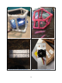
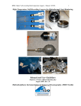
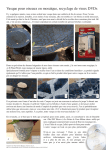
Seawater vs. Brushless Motors
Experiment
Long term solution for using brushless motors. Three different methods were used; silicone mold
release spray, silicone conformal coating, and nothing (control). The three methods were dipping
into a cup filled with a mixture of tap water and salt. Three DC motors were individually treated
and left to sit for several days. After removing them from the solution, the DC motors were
washed and wiped to remove any rust that had accumulated on the magnets.
Result
The silicone spray had the most resistance to rust, so it would be seen as excellent water
repellent. With regular cleaning and re-coating this method would improve the longevity of your
motors. There is also a drop in power when underwater due to short-circuiting effect between
coils. So other possible sealant methods would be polyurethane sealant, epoxy, and marine vinylester resin.
3
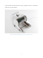
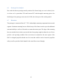
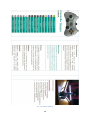
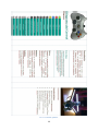
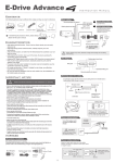
Open ROV 2.6
The OpenROV 2.6 encompasses a very simplistic design directed towards one sole purpose,
exploration. This design does not utilize any external add-ons or functions; in essence it is an
advanced underwater camera with navigation capabilities. The project was started by Eric
Stackpole, along with partner David Lang. The idea began when Stackpole and Lang met three
years ago and began to discuss exchange their ideas for underwater exploration. From the start
the two connected and began to pursue this small idea of theirs that has now evolved into an
enormous project. The OpenRov 2.6 uses three brushless motors for its maneuverability. There is
one centered at the top to control the lift followed by two in the back to control its propulsion. As
a source of energy the ROV uses six C batteries, three on each one of the front extremities. The
design was also focused towards having gaming remote controls as the primary source of driving
the ROV; however, since all of the programming is all open sourced you can format the
programming to your liking or functionality. The advantage to this is it allows people to code
their own add-ons that can then be further modified or utilized by others in the community. With
the initial launch there was a targeted goal of selling $20,000 surprisingly enough they sold that
much within the first two hours. It was at that moment both Stackpole and Lang realized how
large of a calling there was across the world interested in joining the exploration movement. At
this moment they’ve currently sold $111,622 worth of ROV’s. In order to keep it easy to
manipulate the design the two founders are currently not seeking to obtain a patent, at least for
now. The unique thing about this project is the global involvement; "OpenROV is an opensource community," Stackpole said. "If the ROV is having some sort of a problem and we can't
figure out how to handle it, I can go onto the forums and post, 'Hey, this is a problem I'm having,'
and as I sleep, the problem is going across Europe and people who are experts are answering it
4
because they find it interesting. By the time I wake up, it's going to cross the U.S., and by lunch I
can have five or six good solutions."
Figure 1 - Literature Survey, ROV 2.6 [OpenROV | Underwater Exploration Robots]
5
Water Conditions and Propulsion
Thruster design is also an important factor for operating and ROV. In order to choose a proper
thruster apparatus one must first take into account the vehicle’s drag. The formula for drag is:
Typically ROV propulsion systems are divided into 3 categories: electrically driven propeller,
hydraulically driven propeller, and finally, the rarer type being ducted jet propulsion. The
primary concern of thruster design setup is to maximize thrust capabilities while still minimizing
weight. Proper speed considerations are also required since propellers have specific design
speed. ROVs are primarily slower craft that require slower operational propellers. For this
application where depths are limited, diving speed is not terribly important allowing for the use
of slower diving propellers as well.
6
Robotic Manipulator
When considering what kind of a claw we wanted to use, we first had to consider what functions
our claw was going to have. Initially we thought a one degree of freedom robotic claw would
suffice; however, we realized that adding a second degree of freedom isn’t that much more
complicated and drastically improves the range of motion of our claw. The manipulator features
a pan/tilt with a robotic claw equipped with rubber tips at the end to improve its grip. The claw
we selected is made out of stamped aluminum which makes it fairly lightweight in comparison to
the overall weight of the frame. The stamped aluminum is also not a very expensive material as
we are trying to keeps our costs as low as possible. The claw will have two servo motors
independently attached to control the clasping function and pan/tilt features. Compared to other
claws, the one we chose has received a multitude of great reviews online and essentially was the
best deal out there. Not only does the claw accomplish the tasks we sought to achieve but it did it
with the same specs as most of the other claws we looked at a fraction of the price.
7
1.4
Survey of Related Standards
Guide to weatherproofing, weather resistance, and IP ratings
Lorex security cameras are given an environmental rating to indicate their suitability for
installation in different indoor and outdoor environments. This rating is based on the camera's
Ingress Protection (IP) rating. Check the specifications sheet for your camera model to determine
the environmental rating.
Contents:
What is an IP rating?
What does the IP rating mean?
IP rating codes
What rating do I need?
Outdoor installation tips and tricks
8
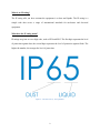
What is an IP rating?
The IP rating tells you how resistant the equipment is to dust and liquids. The IP rating is a
simple code that covers a range of international standards for enclosures and electrical
equipment.
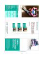
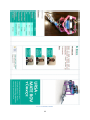
What does the IP rating mean?
IP ratings are given as a two-digit code, such as IP54 and IP65. The first digit represents the level
of protection against dust; the second digit represents the level of protection against fluids. The
higher the number, the stronger the level of protection.
Figure 2 - Literature Survey, IP Explanation
9
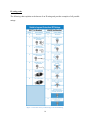
IP rating codes
The following chart explains each element of an IP rating and provides examples of all possible
ratings:
Figure 3 - Literature Survey, Guide to Ingress Protection Rating
10
What rating do I need?
CCTV cameras can be broken down into four classifications of environmental resistance. The
following table explains the required installation environment for Lorex security cameras:
Classification
IP
Rating
Location
Description
Indoor
<44
Indoor
Weather
Resistant
44 - 65
Indoor/ Outdoor
under Shelter
Not intended for submersion in water.
Installation in a sheltered location required
Weatherproof
66 - 67
Indoor/ Outdoor
Not intended for submersion in water.
Installation in a sheltered location
recommended.
Submersible
68
Underwater
Not intended for submersion in water.
Installation in an indoor required.
Full Immersion
NOTE: IP68 submersible cameras are specialized products intended for specific applications (e.g., mounting
on a boat). Cameras rated for full submersion will be clearly labelled. Weather resistant and weatherproof
cameras are not intended for submersion in water.
1.5
Discussion
Overall in this section we went through various studies that relate with multiple past designs. A
brief analysis of the drag in water is discussed as well as a basic analysis of brushless motors in
water. Open ROV is also mentioned for one of their simple underwater robotic designs. A brief
introduction to the Ingress Protection water proofing coding that we used was also presented.
11
2. Project Formulation
2.1
Overview
In this section we will be discussing the main objectives, design specifications, main project
constraints, as well as our global design focus. We will be designing and building an underwater
remotely controlled vehicle that is able to perform successfully within specific environmental
conditions while being within competition guidelines and limitations.
2.2
Project Objectives
The main objective in this project is to design and create an underwater remotely controlled
vehicle that will swiftly complete the required tasks of the competition in a precise manner. The
vehicle will have to complete a variety of tasks some of which are to: be able to visibly inspect
pipelines with an accurate image.
2.3
Design Specifications
When designing an ROV one must first consider the operational environment. Factors such as
salinity, depth, temperature, visibility, and water dynamics. Salinity is a direct measure of the
amount of dissolved salts in the water. While this ROV is expected to operate in only shallow
waters one must still take into consideration expected depth and pressures. For each 33 feet of
depth water pressure increases by approximately 1 atmosphere. Each compartment that is airtight
must maintain that ability at all expected depths. Water conductivity is also an important factor
that helps to evaluate water quality conditions used in primarily research related fields.
12
2.4
Addressing Global Design
When designing any project it is important to take into consideration the scale of global impact
and design. Making your project available and easily understood by as many people as possible
would be the optimal goal. By having the input voltages/ currents, multi-lingual operating
manuals, and a pamphlet indicating the environmental conditions such as temp, salinity, and
security of the design, we are able to branch out to many different groups while keeping the
content clarity simplistic.
2.5
Constraints and Other Considerations
Some of the obstacles we need to keep into consideration include working in shallow, freezing
water conditions. Also we need to keep in mind the difficulty of maneuverability while
underwater while keeping all circuitry sealed and out of contact with the water. The competition
also entails restrictions to size and power which do not let us exceed a 12 volt power supply and
a 25 amp current supply. The vehicle must also be able to maneuver through a 75 cm x 75 cm
hole.
13
3. Design Alternatives
3.1
Overview of Conceptual Designs Developed
In this section, focusing on the proposed designs we examine the proposed designs and narrow
them down into the working design. This is an important teamwork oriented brainstorming
process that allowed for continual revision of designs as a group in real-time. Each team member
brought a different way of thinking and the final design is a reflection of this consolidation of
ideas.
All of our designs had similar aspects such as the motors used for propulsion as well as the
gripper/ claw that would be used to grab and adjust the necessary objects specified by the
competition guidelines. The designs all aim to achieve the same goal which is maneuverability in
icy water and the ability to fit into a narrow space. The main differences between each design is
with the placement of the motors, fins, and electronic enclosures as well as differing outer frame
structures. Some minor features such as lighting and camera placement also change within the
design alternatives for the sake of efficiency and balancing.
14
3.2
Design Alternate 1
Figure 4 - Conceptual Design, 1
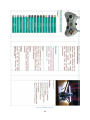
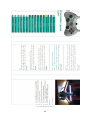
Pictured above is the preliminary design of the ROV. Focusing on 2 forward/reverse thrusters
coupled with 4 up/down thrusters situated in a rectangular metal or PVC frame. The frame has a
metal grating on it sides to allow for higher structural integrity and easier mounting of propulsion
and tools. The thrusters feature reversible propellers to allow for equal operation in opposite
directions. In the center is the “brain” of the ROV. Enclosed is all the electronics of the ROV,
including its motor control units, telemetry acquisition devices, and camera equipment. Relying
on lead shot in the lower parts of the ROV and syntactic foam on the top, the ROV will stay
upright and neutrally buoyant in most conditions.
15
3.3
Design Alternate 2
Figure 5 - Conceptual Design 2
Design two of the underwater ROV mimics the structure of a quad-copter. Focusing on 4 main
forward/reverse thrusters housed in simple motor enclosures, the thrusters feature reversible
propellers to allow for equal operation in opposite directions. In the center is the “brain” of the
ROV, which is affixed to each motor enclosure with a small wiring housing tube. Enclosed is all
the electronics of the ROV, including its motor control units, telemetry acquisition devices, and
camera equipment. Relying on lead shot in the lower parts of the ROV and syntactic foam on the
top, the ROV will stay upright and neutrally buoyant in most conditions. With a gyroscopic
sensor the ROV will be able to detect, at all times, its yaw, pitch and roll, and potentially selflevel so that the plane of action of the ROV is always parallel to the surface plane. This design
has the benefit of being able to move in specific lateral directions as well as up and down with
minimal driving motors.
16
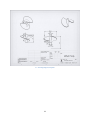
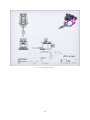
3.4
Design Alternate 3
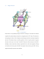
Figure 7 - Conceptual Design, 3 Simulated Model
Figure 6 - Conceptual Design, 3
Pictured above is the most recent design alternative iteration. While similar to some of our
design alternates this design allows for a more modular approach to construction, maintenance,
and troubleshooting. Centered on a square waterproof housing for the control components and
telemetry unit, along with the “brain” of the ROV is a square frame made from aluminum angle.
At the four top corners are brushless motors used to control the elevation of the ROV. Slightly
more inboard and facing the rear are the two other brushless motors used for forward and reverse
propulsion along with yaw capabilities. Additionally, located on the front plane is the main
navigational camera. This is a full color wide angle camera that helps for macro scale navigation.
Additionally, just under the main camera is a smaller, black and white camera, aimed towards the
claw to assist in the finer details of arm manipulation. As with other designs, there will be ballast
located on the bottom plane to provide for increased stability, in addition to the floats used along
the top plane to ensure that the ROV stays properly oriented through all maneuvers.
17
3.5
Integration of Global Design Elements
With our current design we have integrated various global design elements. First and foremost is
the waterproofing and material selection that allows for differing salinity contents of the water.
This allows for operation in more inland countries with only access to freshwater. Additionally,
seawater tested materials allow for deployment in harsher environments. Furthering goals of
global design, the ROV can be powered, with an appropriate inverter, by various countries’
power standards. All documentation will also be provided in multiple languages. Tri-fold
operating brochures will be handed out in multiple languages to each participating staff member.
We are planning in a future installment to provide a converter for the power source ensuring that
URSA can be used regardless of what country you are in.
3.6
Feasibility Assessment
The Marine Advanced Technology Education (MATE) Center is a national partnership of
organizations working to improve marine technical education and in this way help to prepare
America’s future workforce for ocean occupations. The Marine advanced technology education
center has been a National Science Foundation (NSF) Advanced Technological Education (ATE)
Center of Excellence since 1997. The MATE Competition Network began in 2001 and consists
of 24 regional events distributed around the world.
18
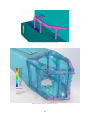
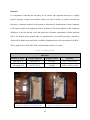
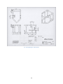
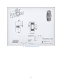
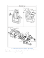
3.7
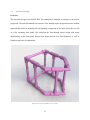
Proposed Design
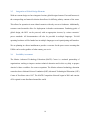
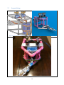
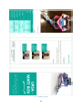
Figure 8 - Proposed Design (Rough without Floats)
Figure 9 - Proposed Design (Rendered)
Figure 10 - Proposed Design (Actual)
19
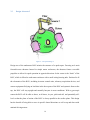
Pictured previously is the most recent design iteration. While similar to some of our design
alternates this design allows for a more solid approach to construction, maintenance, and
troubleshooting. The design is centered on a flow-through frame that encapsulates a waterproof
dive box for the control components and telemetry unit. At the top sits an aluminum bar with
brushless motors affixed, used to control the elevation of the ROV. Mounted on the back in a
similar fashion are the two other brushless motors used for forward and reverse propulsion along
with yaw capabilities. Additionally, located on the front plane is the main navigational camera.
This is a full color wide angle camera that helps for macro scale navigation. The camera is
centered in a way to assist the claw in the finer details of arm manipulation. As with other
designs, there will be weights located on the bottom plane to provide for increased stability, in
addition to the floats used along the top plane to ensure that the ROV stays properly oriented
through all maneuvers.
3.8
Discussion
While we started with a spherical waterproof housing where the electronics would be housed,
with most of the devices attached directly to the housing, we iterated away from this initial
design due to difficulty in obtaining a sufficiently suitable spherical housing. From there, the
next iteration was a pod focused design with the motors attached directly to the central pod.
Once again, this design was abandoned due to cost and ease of manufacture. Finally, we decided
on a more modular rectangular based design with all parts mounted individually. Advantages of
this design include cost savings to build and ease of manufacturing and maintenance.
20
4. Project Management
4.1
Overview
In this section of the report you will be able to see exactly how all the work for the project was
delegated amongst the team members. To begin with we split the project itself into individual
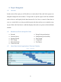
tasks so that we could equally divide them between all of us. Next we created a Gantt chart to
serve as a visual aid for us to keep up with the project due dates and serve as a reminder to stay
on pace. Below the Gantt chart is a table that displays what tasks were given to which individual
member.
4.2
Breakdown of Work into Specific Tasks
4.3
Research
Literature Survey
Structural Design
ROV Design
Material Selection
Control Selection
Design Testing and Analysis
Manufacturing and Assembly
Final Testing
Competition
Final Report
Gantt Chart for the Organization of Work and Timeline
Table 1 - Gantt chart
21
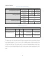
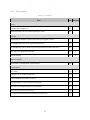
4.4
Breakdown of Responsibilities among Team Members
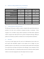
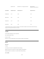
Table 2 - Responsibility Breakdown
Topic
Research
Literature Survey
Structural Design
ROV Design
Material Selection
Control Selection
Design Testing and Analysis
Manufacturing and Assembly
Final Testing
Competition
Final Report
Nikko Miniello
X
X
X
X
Joshua Gonzalez
X
X
XX
Brandon O’Neill
X
X
X
XX
XX
XX
XX
XX
X
X
X
XX
X
XX
X
A single X indicates work was put in while a double XX indicates that this person contributed the majority to this specific aspect.
4.5
Commercialization of the Final Product
The future goal of this project would be to market to companies that require delicate underwater
procedures to be done, such as underwater scavenging, harvesting, or maintenance. Various
companies such as NAVSEA, Odyssey Marine Exploration, and Global Marine Exploration
would be companies that could benefit from our product development and design. Making the
product run as efficiently as possible at a minimal costs is our most prominent consideration.
4.6
Discussion
As you can see in this chapter most of the work we all collaborated on; however, there were
some specific tasks individually assigned to team members who we thought were more
prominent in that area. At the moment we are not currently seeking a patent on the actual design
of our vehicle but are still open to the idea due to the technology we may incorporate. For the
future of this product there is a continually growing outreach for underwater remotely operated
vehicles to execute tasks ranging from some of the simplest to the more complex.
22
5. Engineering Design and Analysis
5.1
Overview
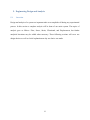
Design and analysis of a system are important tasks to accomplish well during any experimental
process. In this section a complete analysis will be done of our entire system. The topics of
analysis goes as follows: Flow, Stress, Strain, Vibrational, and Displacement, but further
analytical iterations may be added when necessary. These following sections will cover our
design choices as well as a brief explanation on why our choice was made.
23
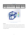
5.2
Kinematic Analysis
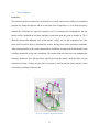
The Kinematic Analysis is performed by setting up our frame in a simulated space with an
approximate velocity of 20 MPH in the direction of motion. By setting up in this manner we are
able to accurately mimic the underwater motion that our system would undergo. The pressure is
set to 29 kPa (4.2 psi) which is the pressure of water at 3 meters (9.8 feet). The water is also set
to be at ambient temperature.
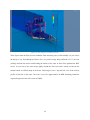
Figure 11 - Flow Analysis, URSA Trajectory Vectors
24
Figure 12 - Flow Analysis, Trajectory Cut Plot
Figure 13 - Flow Analysis, 3D Isosurface Flow
25
Ambient Conditions
Table 3 - Flow Analysis, Ambient Conditions
Variable
Data
Thermodynamic parameters
English
Static Pressure
Temperature
Velocity parameters
Velocity X
SI
4.2 [psi]
29000 [Pa]
68 [F]
293.20 [K]
20 [MPH]
9 [m/s]
Velocity Y
0
Velocity Z
0
Intensity
0.10%
Turbulence parameters
Length
0.079 [in]
0.002 [m]
Table 4 - Flow Analysis, Goals
Goals
Name
Unit
Value
Delta
Criteria
SG Normal Force (Y)
[N]
-0.030
0.0278165496
0.0325425218
[lb-f]
-0.007
0.00625340856
0.00731584931
The goals values come from the upward lift that is generated from the frame having flowing
water running through it. As you can see the force is slightly negative which means the object
will sink when left alone. The results came out as expected, generating higher pressure zones
with a lower velocity around the pipes that come in direct contact with the oncoming flow of the
water.
26
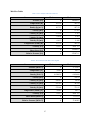
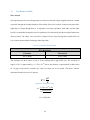
Min/Max Tables
Table 5 - Flow Analysis, Min/ Max Values SI
Name
Minimum
Maximum
Pressure [Pa]
0
188020.87
Temperature [K]
293.16
293.22
Density [kg/m^3]
997.53
997.58
Velocity [m/s]
0
13.993
Velocity (X) [m/s]
-13.220
2.512
Velocity (Y) [m/s]
-9.854
9.852
Velocity (Z) [m/s]
-9.413
9.448
Temperature (Fluid) [K]
293.16
293.22
Vorticity [1/s]
0.257
9603.175
Shear Stress [Pa]
0
159020.87
Relative Pressure [Pa]
0
352567.11
Table 6 - Flow Analysis, Min/ Max Values English
Name
Minimum
Maximum
Pressure [lbf/in^2]
0
27.27012
Temperature [°F]
68.02
68.13
Density [lb/in^3]
0.036039
0.036040
Velocity [in/s]
0
550.92
Velocity (X) [in/s]
-520.45
98.90
Velocity (Y) [in/s]
-387.95
387.89
Velocity (Z) [in/s]
-370.60
371.95
Temperature (Fluid) [°F]
68.02
68.13
Vorticity [1/s]
0.257
9603.175
Shear Stress [lbf/in^2]
0
0.11379
Relative Pressure [lbf/in^2]
0
23.06403
27
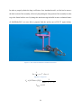
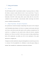
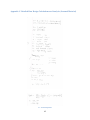
In order to properly obtain the drag coefficient of our simulated model, we first had to remove
the back section of the assembly, effectively disjointing the front portion of the assembly in order
to get the frontal surface area. By doing this and then using the build in mass evaluation feature
of SolidWorks2013, we were able to properly find the surface area of 259.75 square Inches.
Figure 14 - Flow Analysis, Rendered Assembled Front Section
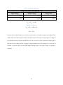
𝐹𝐷 =
1
∗ 𝜌 ∗ 𝑣 2 ∗ 𝐶𝐷 ∗ 𝐴
2
Equation 1 - Drag Force
𝐶𝐷 = {𝐺𝐺 𝐹𝑜𝑟𝑐𝑒 (𝑋)1} ∗
2
1000 ∗ (92 ) ∗ (. 17)
𝐶𝐷𝑎𝑣𝑔 = 0.11
28
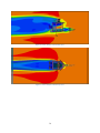
Figure 15 - Flow Analysis, Assembled Isosurface
These figures show the flow of water around the frame and inner pieces of the assembly. As you can see
the design is very flow-through and allows for a very small average drag coefficient of 0.11. the claw
pointing outwards also assists with breaking the tention of the water in front of the path that the ROV
travels. As you can see the water wraps tightly around the claws base and is mainly resisted by the
shrouds which are affixed ontop of the frame. Following we have a top and side view of the velocity
profiles of the flow in the water. The water is set to be approximately 20 MPH simulating around the
expected top speed of our final version of URSA.
29
Figure 16 - Flow Analysis, Cut Plot Side View
Figure 17 - Flow Analysis, Cut Plot Top View
30
5.3
Dynamic/ Vibration Analysis of the System
Overview
Due to the high rotational speed of our motors (720kV) a large amount of vibration is produced.
The oscillation caused by the motor as well as by the thrust generated by the propeller is
observed to be a critical aspect that we need to consider within our design. Ensuring that the
system will not fail under vibrational load, as well as ensuring that the systems supports will not
come undone during operation are two key factors that we have accounted for in our design.
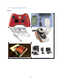
Pelican Micro 1060
The premise of absorbing or dampening the produced vibrations was accomplished by affixing
our electronic components to a, “Thermal Plastic Rubber Liner” that comes standard with the
Pelican Micro 1060 series dive box. This in turn doesn’t diminish the amount of vibrations
produced from the motors, but lessens the impact upon our electronic components.
Aluminum Mounting Bar
The second step we took to limit the amount of vibrations that impact our apparatus was to affix
the motors to aluminum mounting bars. Aluminum has relatively good vibrational damping
factor as well as a reliable strength to weight ratio; which overall when compared to its cost
make for the optimal choice for our specific purpose. We used four ¼ inch bolts per aluminum
mounting bar to provide an even and distributed surface fixture to the frame. Each of the bolts
were individually coated with a later of LOCTITE® THREADLOCKER BLUE 242® which
prevents loosening of metal fasteners caused by vibrations and is removable if necessary. An
additional layer of marine grade sealant was also applied to the screw joint itself to prevent any
water from washing away the Loctite.
31
Motor Screws
As stated previously our motors generate a significant amount of vibrational load; the vibration
was observed to be sufficient enough to rattle the nuts loose from the screws if left unattended.
By using washers and Loctite for each screw holding the motors legs to the surface of the
aluminum mounting bar we were able to tightly fashion a secure grip in which prevented the
screws from coming undone. Since the propellers are threaded to the collet, it was necessary to
apply a liberal coating of Loctite to the threaded surface and to the nut that locks the propeller to
the motor shaft.
Discussion
The process of minimalizing the impact of the vibrations on the system is a fundamentally
essential design consideration. Limiting the vibrational impacts has both a safety and
functionality purpose to it. Our foresight on this aspect of our design has helped to save us a lot
of potential headache and concerns.
32
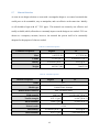
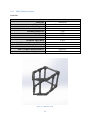
5.4
Structural Design
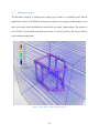
Overview
The structural design of our MATE ROV has undergone a multitude of changes as our project
progressed. The main fluctuation was between a flow-through square design and a more modular
approach that relied on mounting all corresponding components to the main circuit box as well
as a flat, mounting, base panel. We settled on the flow-through square design with minor
modifications to the front panel because that design had the best fluid dynamics as well as
simplicity and ease of construction.
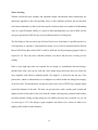
Figure 18 - Structural, Rendered PVC Frame
33
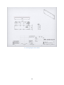
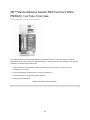
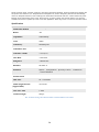
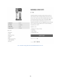
Water Proofing
Without a doubt the most complex and important design consideration when constructing any
underwater apparatus is the water proofing. Since we have multiple electronic devices that need
to be housed internally we had to look into specific enclosures that were capable of withstanding
water at a specified depth. Ideally we wanted to find something that was rated to IP68, but the
cost goes upward from $200 for any sort of prefabricated device of that grade.
The first thing we did was take a trip to Divers Direct to see what kind of a possible product we
could purchase or reproduce. Upon detailed research we were able to determine that the Pelican
Micro 1060 Diving Box rated to IP67 would be sufficient for the prototyping purposes that we
required it for. The only issue with this enclosure was that it did not have an entry port for
cabling.
Since a water tight entry tube was required for our design, we immediately discussed using a
threaded tube with a hex nut on each end. After ample design discussion this was clearly the
most simplistic and effective method possible. We tapped a ¾ inch hole into the top of the
pelican box, which we determined to be an adequate size which would not damage the integrity
of the box itself. The threaded tube was put into place with a layer of PTFE tape wrapped tightly
around the diameter of the tube. The tube was put into place with a marine grade sealant and
tightly secured at both ends of the lid so that the sealant could properly permeate both surfaces
providing optimal coating and preventing any air bubbles that may have persisted. As you can
see from figures 19-23 the design is quite simplistic and allows for a cluster of cables to be
tightly packed within its inner diameter.
34
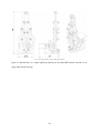
Figure 19 - Structural, Wire Entry Simulation (Top View)
Figure 20 - Structural, Wire Entry Simulation (Top View Sectional)
Figure 21 - Structural, Wire Entry Simulation (Close up - Sectional)
35
Figure 22 - Structural, Wire Entry
Figure 23 - Structural, Wire Entry (Angled View)
36
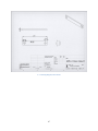
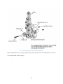
5.5
Force Analysis
Overview
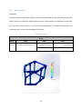
The structure has been modeled as a solid body as to avoid contact errors within our simulation
program. By fixing the opposite end as to where the force is applied to, we were able to properly
indicate the reflected force upon the structure. First by simulating the mounting bar that the
motors will be mounted on and then applying a point load upon the point of contact of 5 lb.-f
(Which is beyond the indicated force of the motors, 1200g), we are able to properly see if the
beam itself would be able to withstand the motors driving force under maximum conditions.
After ensuring that the beam could withstand these conditions we subject the frame that the beam
would be mounted to, to the same conditions. This ensures that our frame can even withstand the
potential, maximum force that the beam could exert from the motors. With this data we also
calculate the factor of safety to make sure our system is well beyond the safety margin, before
we actually would physically test this.
Figure 24 - Simulation, Model Information
37
Table 7 - Loads and Fixtures
Resultant Forces
Components
X
Y
Z
Resultant
Reaction Force [lbf]
-9.97681
0.00530925
-10.7786
14.6873
Reaction Force [N]
-44.3791
0.0236167
-47.9457
65.3322
Load Name
Load Image
Force-1
Load Details
5 [lbf]
22.24 [N]
Force-2
5 [lbf]
22.24 [N]
Force-3
5 [lbf]
22.24 [N]
Gravity-1
386.22 [in/s^2]
9.81 [N]
38
Discussion
From the 5 lb-f point loads that are applied on each of the joints between the aluminum mounting
bar and the frame a resultant force of 14.7 lb-f (65 N) is generated. Due to the solid construction
of our frame we believe that we would have no problem withstanding that applied load, which is
discussed in the following sections.
39
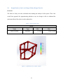
5.6
Stress Analysis
Overview
From the point loads described in the previous section increased stresses and strains in the frame
and its joints are created. By using the built in stress/ strain analysis of SolidWorks which using
the Von Mises Stress theory as well as the Equivalent Strain to calculate the minimum and
maximum stress/ strain values throughout the system.
Table 8 - Stress Table
Stress
Name
Type
Min
Stress
VON: von Mises Stress
Max
0.000827975 [psi]
619.654 [psi]
5.70869 [N/m^2]
4.27237e+006 [N/m^2]
Figure 25 - Simulation, Stress Analysis
40
Table 9 - Strain Table
Strain
Name
Type
Strain
ESTRN: Equivalent Strain
Min
4.16807e-009
Max
0.00125933
Figure 26 - Simulation, Strain Analysis
Discussion
Similar to the method we used for the Force Analysis section, we also simulated a solid body as
reference to the frame. From the data gathered from a continuous load on the structure a stress
and strain analysis was performed. A max value of 620 psi and 0.00125933 were produced from
the resulting calculations.
41
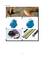
5.7
Material Selection
As seen in our design selection we went with a rectangular design so we wanted a material that
would prove to be sustainable, easy to manipulate, and cost effective at the same time. Initially
we all decided to begin with 0.5’’ PVC pipes. This material was extremely cost effective and
readily available; which, allowed us to constantly improve on the design as we worked. PVC was
chosen as a temporary measure; however, the material has proven itself to be structurally
adequate for the purpose of what we needed.
Table 10 - Volumetric Properties
Volumetric Properties
English
SI
Mass
0.823555 [lb]
0.373558 [kg]
Volume
22.3489 [in^3]
0.000366234 [m^3]
Density
0.0368498 [lb/in^3]
1020 [kg/m^3]
Weight
0.822997 [lbf]
3.66087 [N]
Table 11 - Material Properties
Material Properties
English
SI
PVC
Name
Model type
Linear Elastic Isotropic
Default failure criterion
Max von Mises Stress
Yield strength
8000 [psi]
5.51581e+007 [N/m^2]
Tensile strength
4351.13 [psi]
3e+007 [N/m^2]
Elastic modulus
290075 [psi]
2e+009 [N/m^2]
0.394
Poisson's ratio
Mass density
0.0368498 [lb/in^3]
1020 [kg/m^3]
Shear modulus
46252.5 [psi]
3.189e+008 [N/m^2]
42
5.8
Design Based on Static and Fatigue Failure Design Theories
Overview
The factor of safety was also calculated when running the analysis of the system. This is the
overall best approach for approximating whether or not our design is able to withstand the
maximum allotted force that it can be subjected to.
Table 12 - Factor of Safety Table
Strain
Name
Type
Factor of Safety
Automatic
Min
12.9104
Figure 27 - Simulation, Factor of Safety Analysis
43
Max
9.66213e+006
Discussion
In order to be perfectly safe when designing our frame, the minimum factor of safety is the
important value to assess. The simulation produced a value of 12 for our safety factor which we
believe to be more than required for our design; this number is taking into account for load much
higher than what we expect to experience.
44
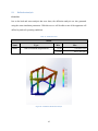
5.9
Deflection Analysis
Overview
Just as the load and stress analysis that were done, the deflection analysis was also generated
using the same simulation parameters. With this test we will be able to note if the apparatus will
deflect beyond safe operating conditions.
Table 13 - Deflection Table
Strain
Name
Type
Min
Strain
URES: Resultant Displacement
0 [in]
0.0128933 [in]
0 [cm]
0.0327489 [cm]
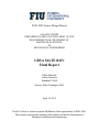
Figure 28 - Simulation, Deflection Analysis
45
Max
Discussion
Again in order to test for the optimal conditions of the frames safe operation, the maximum value
of the deflection will be the number that is important. While most of the solid body is practically
unaffected by the force load, the maximum observed deflection of the frame is approximately
0.013 in.
46
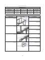
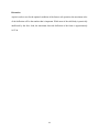
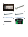
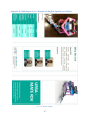
5.10
Component Design/ Selection
Devices
Figure 29 - Component, Xbox 360 Control
Figure 30 - Component, Xbox 360 Wireless Receiver
Figure 31 - Component, Robotic Claw - MKII
Figure 32 - Component, Robotic Claw Pan/Tilt Bracket
- MKII
Figure 33 - Component, Arduino UNO
Figure 34 - Component, GoPro Hero 3
47
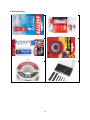
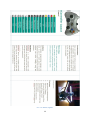
Functionality
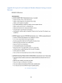
Figure 35 - Component, HobbyKing Donkey ST3508
730KV Brushless DC Motor
Figure 36 - Component, Octura X470 1.4 Dia.
Beryllium Copper Propeller
Figure 37 - Component, HS-5086WP Metal Gear, Micro
Digital Waterproof Servo
Figure 38 - Component, HS-5086WP Metal Gear, Micro
Digital Waterproof Servo
Figure 39 - Component, HobbyKing Brushless Car ESC
100A
Figure 40 - Component, Astra Depot Aluminum High
Powered 6W 6000k Xenon White LED
48
Finishing Products
Figure 41 - Component, Loctite Threadlocker blue 242
Figure 42 - Component, 3M™ Marine Adhesive Sealant
5200 Fast Cure
Figure 43 - Component, JB Weld WaterWeld Epoxy
Putty
Figure 44 - Component, Scotch Outdoor Mounting Tape
Figure 45 - BenzOMatic Solder Core Rosin
Figure 46 - Component, Assorted Shrink Wrap
49
Misc
Figure 47 - Everbilt Flat Bar Aluminum
Figure 48 - Component, Hex Bolt (1/4 in x 1-1/2 in)
Figure 49 - Component, Everbilt Zinc Machine Screws
Round Head Combo #8-32x1-1/2 inch
Figure 50 - Component, Everbilt Zinc Machine Screws
Round Head Combo #8-32x1-3/4 inch
Figure 51 – Component, Southwire Landscape Wire
Figure 52 - Component, Cerrowire Appliance Wiring
50
5.11
Finite Element Analysis
Overview
Mesh Details
Mesh type
Mesher Used:
Jacobian points
Maximum element size
Minimum element size
Mesh Quality
Total Nodes
Total Elements
Maximum Aspect Ratio
% of elements with Aspect Ratio < 3
% of elements with Aspect Ratio > 10
% of distorted elements(Jacobian)
Time to complete mesh(hh;mm;ss):
Computer name:
Figure 53 - Simulation, Mesh
51
Solid Mesh
Curvature based mesh
4 Points
0 [in]
0 [in]
High
95008
54561
8.5054
99.2
0
0
00:00:16
NIKKO-PC
5.12
Design Overview
The structural design of our MATE ROV consists of a flow-through hollow frame design which
incorporates aluminum mounting bars which the 2-DOF manipulator arm as well as the Pelican
Diving Box are affixed to. The structure has been modeled as a solid body made out of PVC to
avoid contact errors within our simulation program, although the pipes are still hollow. By fixing
the opposite end as to where the force is applied to, we were able to properly indicate the
reflected force upon the structure. First by simulating the mounting bar that the motors will be
mounted on and then applying a point load upon the point of contact of 5 lb-f a good
approximation of the systems operating conditions can be determined. An overall factor of safety
of 3 for the system was observed indicating that our design was a success and can withstand
more than what our motors produce.
52
5.14
Cost Analysis
Table 14 - Cost Analysis
Part
Cost Donated
Power
Computer Power Supply 12V
$30
HobbyKing Donkey ST3508 730KV Brushless DC Motor
$40
Control
HobbyKing® ™ Brushless Car ESC 100A w/ Reverse (Upgrade version)
$111
HS-5086WP Metal Gear, Micro Digital Waterproof Servo
$43
HS-5646WP High Voltage, High Torque, Programmable Digital Waterproof Servo
$42
Microsoft Xbox 360 Wireless Controller
$60
X
Arduino UNO Kit
$50
X
Maneuverability
Octura X470 1.4 Dia Beryllium Copper Propeller
$80
Functionality
PVC Piping
$130
X
GoPro Hero 3 /W Underwater Enclosure
$200
X
Robotic Manipulator Assembly (No Servo)
$70
Propeller Adapter to suit 5.0 mm motor Suit (Collet)
$20
Microsoft Xbox 360 Wireless Receiver for Windows
$15
Pelican Micro 1060 Underwater Diving Box
$28
Astra Depot Aluminum High Powered 6W 6000k Xenon White LED
$12
53
X
Part
Cost Donated
Miscellaneous
Everbilt Flat Bar Aluminum (2 in x 1/8 in x 36 in)
$11
Everbilt Zinc Machine Screws Round Head Combo #8-32x1-1/2 inch (6pk)
$6
Everbilt Zinc Machine Screws Round Head Combo #8-32x1-3/4 inch (8pk)
$1
Hex Bolt (1/4 in x 1-1/2 in)
$2
Hex Nut Zinc (1/4 in)
50¢
Southwire Low Voltage Landscape Wire Black Stranded RoHS Compliant 14/2 (50 ft)
$22
Cerrowire Appliance Wiring Rated T90 Nylon 105 Degrees C (50 ft)
$10
Heat Shrink Tubing Assorted Pack (150 pcs)
$7
BernzOmatic Electric Solder Lead-Free Rosin Core (3 oz)
$7
3M Marine Adhesive Sealant 5200 (3 fl oz)
$8
Scotch Outdoor Mounting Tape (1.66 YD)
$5
JB WATERWELD EPOXY PUTTY (2 oz)
$8
54
5.15 Discussion
At this moment the total amount we would spent on our current parts list is right around $1020.
We were looking for alternatives to reduce the cost without affecting the quality. This is one of
the features we want to iterate on that separate us from previous models. We were budgeted
initially to spend right around $600-$700 so we planned to reduce our overall cost anywhere
from $150-$250 in order to meet our goal. We are seeking to implement a design that can
perform just as well or better than other models but at a fraction of the price. Some of the more
expensive components were donated to us from either close friends or small business owners,
effectively reducing our planned spending to approximately $488. This is a good range for us
since we are self-funded and have no specific sponsors to our name. We also ordered additional
parts for trial and error, these specific components are not included in the cost analysis, but the
total amount comes out to approximately $150. Our cost analysis doesn’t include taxes and
shipping; with those added expenses the total cost should come out to be around $1200.
We overshot out budget quite a bit from our initial assumption. This price doesn’t even include
our trial and error purchases which we did not use in our final design. The reason for such a large
oversight was because we didn’t account for all the minor fixings and sealants that would end up
coming out to a few hundred dollars in the end. We feel that the initial goal of around $600 is
still possible if all of the research and trial and error we have accomplished would have been
done prior to starting this project. The price compared to other similar model underwater ROVs
is still relatively inexpensive, which we find to be one of our most redeeming characteristics.
55
6. Prototype Construction
6.1
Overview
In chapter six you will read about all the considerations taken to implement the final design into
a prototype. This chapter outlines all the individual components, cost, and design overview for
the prototype. Also included in this chapter is an overview of the actual construction of the
prototype so that you can see exactly how the vehicle was put together.
6.2
Description of Prototype
The overall design of the MATE ROV will be centered on the idea of a central, water-tight,
enclosed main body that houses the electrical components that govern the control and data
gathering of the system. A sealed camera will be used to gather optical and sensory data which
will be then be analyzed onshore via a laptop display. A robotic claw will be used to physically
move or adjust specific objects in question. The whole body will be constructed out of water
resistant materials such as PVC and Nylon. Any moveable components will rely on water-safe
bearings.
6.3
Prototype Design
Initially we went with a more rectangular design because we thought the bull bar (angled frontal
bars) in the front would make mounting things easier; however, it proved to not be that beneficial
so we switched back to a more square design. The bars at the front of the design will serve for
mounting our lights. We are planning on housing the electronics in a dive box that we will have
to mount towards the center of the ROV. In addition we are leaving some space towards the back
just in case we want to put our horizontal thrusters mounted internally too.
56
Figure 54 - Prototype 01 View 01
Figure 55 - Prototype 01 View 02
Figure 56 - Prototype 02 View 01
Figure 57 - Prototype 02 view 02
57
Figure 58 - Prototype Frame with Loose Housing
Figure 59 - Prototype Painted Frame
Figure 60 - Prototype Aluminum Mounting Bars
Figure 61 - Prototype Motor Mounted
58
6.4
Parts List
Table 15 - Part List
Part
Count
Power
Computer Power Supply 12V
1
HobbyKing Donkey ST3508 730KV Brushless DC Motor
4
Control
HobbyKing® ™ Brushless Car ESC 100A w/ Reverse (Upgrade version)
3
HS-5086WP Metal Gear, Micro Digital Waterproof Servo
1
HS-5646WP High Voltage, High Torque, Programmable Digital Waterproof Servo
1
Microsoft Xbox 360 Wireless Controller
1
Arduino UNO Kit
1
Maneuverability
Octura X470 1.4 Dia Beryllium Copper Propeller
4
Functionality
20’
PVC Piping
GoPro Hero 3 /W Underwater Enclosure
1
Robotic Manipulator Assembly (No Servo)
2
Propeller Adapter to suit 5.0 mm motor Suit (Collet)
4
Microsoft Xbox 360 Wireless Receiver for Windows
1
Pelican Micro 1060 Underwater Diving Box
1
Astra Depot Aluminum High Powered 6W 6000k Xenon White LED
3
59
Part
Count
Miscellaneous
Everbilt Flat Bar Aluminum (2 in x 1/8 in x 36 in)
1
Everbilt Zinc Machine Screws Round Head Combo #8-32x1-1/2 inch (6pk)
5
Everbilt Zinc Machine Screws Round Head Combo #8-32x1-3/4 inch (8pk)
1
Hex Bolt (1/4 in x 1-1/2 in)
8
Hex Nut Zinc (1/4 in)
8
Southwire Low Voltage Landscape Wire Black Stranded RoHS Compliant 14/2 50 ft)
1
Cerrowire Appliance Wiring Rated T90 Nylon 105 Degrees C (50 ft)
1
3M Marine Adhesive Sealant 5200 (3fl oz)
1
Scotch Outdoor Mounting Tape (1.66 YD)
1
Cerrowire Appliance Wiring Rated T90 Nylon 105 Degrees C (50 ft)
1
Heat Shrink Tubing Assorted Pack (150 pcs)
1
BernzOmatic Electric Solder Lead-Free Rosin Core (3 oz)
1
60
6.5
Construction
To begin with the construction we purchased two 10’ poles of ½ inch PVC piping. With the
acquired PVC we both pipes into segments of 6’’ leaving us with twenty pieces of 6’’ PVC
pipes. We used 6’’ segments because we are trying to achieve an efficient, compact and
economic design. By starting with the 6’’ we could design a larger scale version and always cut
off more PVC. In addition, we purchased six Triple 90’s, 4 T connectors, and four 45 degrees
connectors. The triple 90 pieces were used to construct the rectangular top of the prototype
connected by the 6’’ PVC that was previously cut. Next we took two pieces of the 6’’ PVC and
cut them into 2’’ pieces so that we could connect the T pieces relatively close. The T connectors
were used to have PVC run from the top to bottom of the design for frame reinforcement and
motor mounts. Coming out the other end of the T connector was some more of the 2’’ pieces that
now connect to our 45 degree elbows which give the design its triangular shape. At the end is
another triple 90 which connects to the 45 degree elbows and also runs a 6’’ piece from the top
and bottom for additional frame support. For the prototype construction we strictly used PVC for
the frame. Aluminum mounting bars for the motors were placed upon the back and top of the
frame and an aluminum mounting bar for the robotic manipulator was affixed to the fascia of the
frame. Two high powered 6 W 6000k LED Arrays are affixed to the front bottom segment of the
frame to ensure that the water we are navigating is always well lit. A high definition camera
(GoPro Hero 3) is mounted to the front of the frame above the manipulator claw to ensure that
the claw and front of the apparatus is always visible on screen.
61
6.6
Prototype Cost Analysis
Due to the fact that our prototype mainly consists of the frame design, our cost is relatively low.
As of now we’ve spent about $130 total between PVC and the angled connecting pieces. Our
final design of our prototype comes out to be $1020, this is the price of the working model.
6.7
Discussion
The prototype is constructed from 0.5’’ PVC with multiple connecting components between each
segment. Aluminum mounting bars are affixed on top of the frame in order to provide additional
structural stability as well as a flat surface to mount the motors upon. The edges of the mounting
bars are smoothed out in order to prevent the bars from getting caught on obstacles as well as to
provide a safe operating condition. Since our motors are mounted on the outer regions of the
ROV we designed propeller shrouds out of tin cans that could be used to house the propellers
safety as well as provide a fitted channel for the water flow to travel through.
62
7. Testing and Evaluation
7.1
Overview
The MATE underwater ROV is tested within the confines of a private pool where we will have
the freedom to maneuver around without the risks of various outside factors. The pool is
confined to a depth of 6 feet so it will be mainly used for the purpose of testing the controls and
functionality of the ROV. Further testing within a private facility and/or the ocean will be
considered in order to test the ROV’s various functions within a much larger scale with the
presence of multiple environmental factors.
7.2
Design of Experiments – Description of Experiments
Our experiments are centered on testing the waterproofing of the system as well as testing the
overall functionality and performance. Our first test is to attempt to run the system under strain
out of water to ensure that our motors and controls are able to perform at an optimal state. The
second test is to submerge the water proofed sections without the electronic components
underwater to see if there are any leaks, if a leak occurs a pressure test using a pump and spray
bottle will be implemented. Any further tests will be for the performance of the system
underwater in a completed state.
Testing the wires before and after the voltage travels through them to account for any power loss
is a necessity. We will accomplish this via a Multimeter to ensure that proper readings are
indicated. This is intended to be a confirmation to our theoretical calculations.
63
7.3
Test Results and Data
Wire Analysis
One important aspect to test of the apparatus is to make sure that the voltage supplied remains as constant
as possible through the extended distances of the cabling. Since all wires have an internal resistance and a
slight drop of voltage through them, it is important to test these parameters, both under and not under
load. We accomplished testing these specific parameters first theoretically and then compared them to the
observed values. The values were read off of a Square D Power Logic Energy Meter which allows for
very accurate measurements of amperage under high loads.
Table 16 - Test Results, Wire Resistance
Wire Resistance
Calculator
Theoretical
0.079 [ohm]
0.024 [ohm]
The parameters for these values are set to 50 feet cabling and 12 gage AWG wire. The resistivity of
copper at 20 C is approximately 𝜌 = 1.724 ∗ 10−8 𝑜ℎ𝑚 𝑚 the diameter is approximately 0.0808 inches
for 12 gage wiring and the resistance per 1000 feet comes out to be around 1.588 ohms. And the
maximum allowable current is 41 amperes.
𝜌𝐿
𝑅=
𝐴
Equation 2 - Resistance of a Wire
𝑅=
(1.724 ∗ 10−8 )(50)
𝜋(
0.00673333 2
)
2
𝑅 = 0.024 𝑜ℎ𝑚
64
Table 17 - Test Results, Voltage Loss
Voltage Loss (Nickle Metal Hydride 7.2V)
Input Voltage
Output Voltage
Voltage Loss
8.4[V]
7.8[V]
0.6[V]
12[V]
11.4[V]
0.6[V]
𝑉𝑜𝑢𝑡 = 𝑉𝑖𝑛 − (𝐼 ∗ 𝑅)
Equation 3 - Voltage Loss
𝑉𝑜𝑢𝑡 = 12 − (.024 ∗ 25)
𝑉𝑜𝑢𝑡 = 11.4
From the values indicated above we were able to see that there is a minimal voltage loss through the 50 ft
cabling. This is the ideal scenario because it will ensure that our device gets an ample supply of voltage to
the components that are housed within the dive box. The wire that was used is Southwire landscape Wire
that runs for low voltage and has 14 gauge 2 copper stranded wires. The voltage loss is very low as
assumed; if you take into an account much higher amperage such as 100 amps a larger loss would be
expected.
65
Buoyancy
It is important to calculate the buoyancy of our system. Our apparatus must have a slightly
positive buoyancy so that it can resurface slowly over time if need be. In order to calculate the
buoyancy a volumetric analysis of the system to determine the displacement of water compared
to the actual weight of the apparatus must be performed. The major addition to the volumetric
differences is the fact that the cavity that houses the electronic components is hollow and thus
full of air. Results below indicate that our apparatus has very small, but positive buoyancy,
which will be further increased when we add the floatation foam to the top portion of the ROV.
This is good because if the ROV fails it will naturally resurface over time.
Table 18 - Test Results, Buoyancy
Buoyancy
Density of Water
Volume Displaced
Weight of URSA
Buoyancy
1000 [kg/m^3]
0.00095 [m^3]
0.94 [kg]
0.95 − 0.94 = 0.01
1.940 [slugs/ft^3]
0.03355 [ft^3]
2.08 [lb]
2.094 − 2.08 = 0.014
Figure 62 - Testing Results, Testing Divebox 1
Figure 63 - Testing Results, Testing Divebox 2
66
Water Proofing
The most challenging aspect of the project was getting the electrical components to be in a small
enough vessel to fit within our frame, while being large enough for heat dissipation and at the
same time remaining water tight. We did several layers of testing to ensure that the electrical box
would not have any leaks.
First and foremost we put a thin layer of water absorbent cloth within the unaltered Pelican
Micro 1060 Dive Box. After placing the moisture indication cloth within the dive box we ran a
high power hose over the box to check to see if any water with high pressure could penetrate the
box or cause the hinges to open. With the success of this test we placed the box at the bottom of
a 3 foot pool and slowly moved it toward the depth of 6 feet and kept it there for a prolonged
period of time slowly rotating it around to make sure no bubbles were forcibly keeping out the
water. We then removed the water absorbent cloth and closely analyzed it for any moisture that
could have seeped in.
After successfully passing the previous tests we were able to go onto the next stage of adding the
wire entry tube which was shown previously in figures 19 – 23. The altered box went through the
same process of testing as the unaltered iteration, but with a pressurized cap preventing any
water from leaking into the box from the tubes opening before the wire and sealant was added.
This process was repeated again after the ROV was fully assembled and all of the electronic
components were added in.
67
Motor Output
Since we lack the proper equipment to measure the motors RPM observationally the best method
to measure the speed was by theoretical calculations.
𝑅𝑃𝑀 = 𝑉 ∗ 𝑘𝑉
Equation 4 - RPM
𝑅𝑃𝑀 = 18 ∗ 720
𝑅𝑃𝑀 = 12960
And the horse power surmounts to
𝐻𝑃 =
𝐼∗𝑉
745.7
Equation 5 - Horse Power
𝐻𝑃 =
100 ∗ 18
745.7
𝐻𝑃 = 2.41
The value provided for horse power is assuming we are able to produce amperage of 100 amps
which is the max of the electronic speed controls, but in actually the wire is limited to 41 amps
and we are in actuality only able to produce around 1 HP. The motors are only capable of
accepting 35 amps with a power output of 330 W or 0.44 Hp. So under the best conditions with
minimal power lose we can expect a horsepower of around 0.40.
68
Propellers
The output potential of the propellers coupled with the motors is definitely important when it
comes to calculating the theoretical speed and from that the theoretical force that would be acting
upon the apparatus at the expected depth.
Table 19 - Testing Results, Propeller
Octura Propeller
Prop#
X470
Diameter
70 [mm]
Pitch
1.4 ∗ 2.76 = 3.864 [in]
2.76 [in]
𝑣=
Shaft
¼ [in]
𝑅𝑃𝑀 𝑃𝑖𝑡𝑐ℎ
𝑆𝑙𝑖𝑝
∗
∗ [1 − (
)]
𝑟𝑎𝑡𝑖𝑜
𝐶
100
Equation 6 - Speed of Propeller
𝑣𝑚𝑎𝑥 =
720 ∗ 18 3.864
0
∗
∗ [1 − (
)]
1
1056
100
𝑣𝑚𝑎𝑥 = 47 𝑀𝑃𝐻
𝑣=
720 ∗ 18 3.864
50
∗
∗ [1 − (
)]
1
1056
100
𝑣𝑒𝑥𝑝 = 23.71 𝑀𝑃𝐻
𝑣𝑚𝑎𝑥 Is the max possible speed assuming the brushless motor has no slippage, while 𝑣𝑒𝑥𝑝 is the
expected speed if the motor slips 50%. This is a theoretical average not the actual speed
observed.
When using MPH the value of C is
𝐶 = 1056
When using KPH the value of C is
𝐶 = 656
69
7.4
Evaluation of Experimental Results
The experimental results yield very compelling data. We can see that the theoretically the system
is sound and produces the desired results we were looking for in an effective manner. The
machine is very capable of running the full course that it is supposed to without losing the
integrity of the hull due to the vibrations and force applied on the system. With a positive
buoyancy of 0.01 the system will self-resurface which was one of our important goals. The
voltage drop across the wires is very small which we observed by how well the motors
preformed under continuous load.
Our frame has no problem handling the force and torque generated by the motors and with the
Loctite we added to the threading the bolts have not come undone.
70
7.5
Improvement of the Design
Improvements on any design could always be made; the difficult parts are if the changes are
plausible.
Structural
Having a lighter frame with the same or similar structural stability would be ideal, to accomplish
this we would need to construct the chassis out of titanium or aluminum which would provide
ample strength to weight ratio compared to PVC. Flattening the front of the frame would allow
for better mounting of the claw and lights, as well as simplify the design overall. Adding on
bumpers for the safety of the claw is also a thought about improvement. Ideally if we were able
to get our system to be rated an IP68 we would be able to go much deeper in the water for longer
periods of time without the worry of minor leaks getting into the circuitry.
Power
More efficient and powerful motors that are constructed specifically for underwater use would be
the ideal scenario. At the moment we are using brushless motors, which are fine for prototyping
or small scale designs underwater, but we would want a motor with an IP68 rating, graded for
deep underwater usage. Higher quality wires that are able to maintain a perfect 12 Volt supply
without dropping over the extended distance would also be a noted improvement.
71
Controls
Making the inputs pressure sensitive is the next step in improving our controller layout and
design. Due to specific time constraints we limited our design to simple on/off motor controls
that use the code to accelerate over time, but we are planning to finish the controller inputs by
making them pressure sensitive. Having an additional control for the use of the claw would also
serve to make the visual process more appealing to the person controlling the ROV.
Price
We put emphasis on the total cost of our design since we first started to draft up the initial
drawings. Since we are on a limited budget and for the most part self-funded; if we overshot
what we could afford we wouldn’t have been able to complete the project. As an improvement
we would have loved to spend more to be able to buy higher IP rated products as well as
professional grade wires and fittings, but overall our idea was to minimize the cost of the total
system so that our design could be used more universally by people of lower income interested in
learning about marine aquatic life. By redesigning the system more effectively I feel we could
cut down the total price by several hundred dollars, namely find the specific parts that get the job
done at the minimal level without being excessive in any way.
7.6
Discussion
Over all a basic redesign of the entire system would be the idealistic thing to do. If cost were no
concern a much lighter and sturdier material would have been chosen as well as a more advanced
and water proofed system. Cost is the greatest limiting factor of all, the choices we made were
centered on us having to self-fund the majority of the design.
72
8. Design Considerations
8.1
Assembly and Disassembly
Ease of disassembly for maintenance purposes are required. While working with water we must
always consider the combination of water and electronics and its effects on short circuiting
components. The bolts are all able to be removed from the motors as well as the mounting bars.
If you take apart those you would be able to remount different motors as long as they are
compatible with our slotting on the aluminum mounting bars. For the most part the only
component that needs to be opened and closed in the central brain of the system, it was
constructed out of a dive box, so it is possible to open the latch if necessary. Any bolt that is
loosened or removed must be Loctite again before operation. To take apart our system you would
only need a small wrench and a Philips screw driver.
8.2
Maintenance of the System
8.2.1 Regular and Major Maintenance
Regular maintenance includes checking for proper operation of thrusters and assuring all seals
are properly lubricated and watertight. Rinsing the DC brushless motors off with some fresh,
clean water after use is suggested as it will promote the longevity of the system. Do not run the
system excessively under high strain, this could cause an overload to the electronic speed
controls housed in the dive box.
8.3
Environmental Impact
While there are no immediate considerations for the environment since this entire project is selfcontained, there is always the chance of small amounts of oil leaking into the water through the
bearings. Additionally, we must be aware of battery disposal.
73
8.4
Risk Assessment
The biggest Risk in our project is if it will fail. Putting any sort of electronic devices underwater
is always a risk that doesn’t have many ways to get around if you make a mistake. If the
electronics get wet we will have a fuse set up as a failsafe. Overall our project has very little risk
because we are keeping our costs and size of our device to a minimum. Our design takes into
account that our system may fail; we chose to make our design with slightly positive buoyancy
so it could self-resurface if needed.
74
9. Design Experience
9.1
Overview
Chapter nine encompasses our overall experience and knowledge gained by participating in this
design project. This section displays the standards used, issues encountered, and overall global
impact. During every stage of the project we needed to keep in mind how we could gear our
project to not only impact our society but societies all across the world. While keeping in mind
the different elements that come into play when trying to make something that has a possibility
of global implementation.
9.2
Standards Used in the Project
12 volts, 25 amps DC. Conversion to lower voltages is permitted topside and on the
ROV. Onboard electrical power is not permitted.
Pneumatics and hydraulics are permitted provided that the team passes the MATE Fluid
Power Safety Quiz and follows the specifications included within the competition
manual.
Lasers are permitted provided that the team follows the specifications included within the
competition manual.
Camera is required.
75
9.3
Contemporary Issues
Yellowstone River is considered one of the greatest trout streams of the world. With the recent
oil spill on January 15th, 2015 leaking approximately 50,000 gallons of oil from a pipeline the
environmental impact will be devastating to the wildlife of the area. This is where our UW ROV
has its purpose. With the use of our simple UW ROV URSA we will be able to do mock testing
for maintenance and supply to the various offshore oil pipelines. Hopefully with regular
scheduled checks and remote unmanned maintenance we would be able to detect possible
damage to a pipeline before it got to the level of extreme leakage.
9.4
Impact of Design in a Global and Societal Context
Our design doesn’t particularly revolutionize the way underwater ROVs have an impact on the
global and societal scale, although ROVs themselves have a huge growing desire. Military has
begun to use remotely operated vehicles underwater now so they can safely deploy a mobile
vision source far away without the need of having a person personally onboard the craft. By
keeping the design simple and small it is possible to cheaply deploy multiple crafts to various
areas minimizing the various risks that having onboard personal would produce. As impact on
society goes, personal boundaries between where is it acceptable to have remotely operated
camera or spying devices would be allowed. There is already an ongoing dilemma in regards to
Quadcopters equipped with cameras on the beach, and this would just be another addition to that
issue.
76
9.5
Professional and Ethical Responsibility
There is a moral and ethical aspect to every project that you work on. It is important that the
work you do is your own and unique to the intellectual rights of the student designing the work.
Enlisting unapproved outside help is also questionable. The product we design should be as we
described and indicated throughout the report. There is a responsibility to be as straightforward
and honest as possible.
9.6
Life-Long Learning Experience
The knowledge gained from this endeavor is unmeasurable. The vast amount of time and
research that is required to make a fully functional UWROV is something that you could only
understand if you try to take on the project yourself. Teamwork and cooperation as well as
prompt time lines and scheduling was a very important aspect of the project that was required.
Without a competent team and a proper time line set forth, the project would never have come to
fruition.
9.7
Discussion
This section has encompassed all of our overall experience and knowledge gained by
participating in this design project. The standards used, issues encountered, and overall global
impact have all been discussed. Every project no matter how big or small has an impact on the
global scale as well as the societal. It is important to keep ethics in mind throughout the project
and ensure that all of what you do is your own. By following these guidelines and paying close
attention to the details a life-long learning experience will be felt.
77
10. Conclusion
10.1
Conclusion and Discussion
Our specific goals that we set out to accomplish were mostly met; we were able to progress to
the level we intended for the prototype. A successful model was built on the concepts we
previously laid out before starting the actual build. Our device preformed successfully under the
heat and force load that was generated from the motors and electronic speed controls having a
theoretical minimum safety value of 12 which is well beyond the required amount. We credit the
exploratory heat dissipation to the fact that our apparatus uses forced convection from cold water
conditions naturally. We were able to get the claw to operate as desired and it was capable of
panning as well as clamping down upon an object without destroying it. URSA theoretically was
able to travel through the water at speeds up to 20 MPH with an average drag coefficient of
around 0.11 which is the expected ideal of our flow-through system that we carefully designed.
78
10.2
Evaluation of Integrated Global Design Aspects
Our idea of producing multiple tri-fold brochures available in multiple languages was the main
focus of our global design. We wanted anyone that would be looking at our operations manual to
be able to comfortably understand what we laid out without having to struggle to figure out the
exact meaning behind each statement. We were able to produce multiple brochures in multiple
languages; they are very clean and easy to understand.
10.3
Evaluation of Intangible Experiences
The amount of technical and realistic experience gained from the completion of this project is
without compare. The sheer amount of work that goes into the design and testing of any
completed project was something very foreign to us as engineering students who have only
experienced textbooks and equations up until now. On top of the amount of work that goes into it
the real life lesson of teamwork and cooperation was thoroughly tested throughout the
assignment.
79
10.4
Commercialization Prospects of the Product
The future goal of this project would be to market to companies that require delicate underwater
procedures to be done, such as underwater scavenging, harvesting, or maintenance. Various
companies such as NAVSEA, Odyssey Marine Exploration, and Global Marine Exploration
would be companies that could benefit from our product development and design. Making the
product run as efficiently as possible at a minimal costs is our most prominent consideration.
Lowering the overall cost of the product while at the same time simplifying the total process of
assembly and maintenance are the key goals to making our product marketable to the public. The
lower cost will allow us to sell the product at a healthy profit margin, while at the same time
making replacement of faulty components a hassle-free process. The simplistic design and hope
for an even further simplistic approach will allow anyone to be able to assembly and use the
product regardless of technical knowhow or experience with engineering. We also aim to make
the device modular so that different components that are approved could be easily swapped on
and off for the specific purposes the user desires, thus also effectively reducing the overall cost
to the consumer based on their specific need.
80
10.5
Future work
We would love to continue working on this design; the time and effort we put in to produce a
working prototype was significant so we wish to finalize our design and produce a complete
working apparatus in the future.
Having a lighter frame with the same or similar structural stability would be ideal, to accomplish
this we would need to construct the chassis out of titanium or aluminum which would provide
ample strength to weight ratio compared to PVC. Flattening the front of the frame would allow
for better mounting of the claw and lights, as well as simplify the design overall. Adding on
bumpers for the safety of the claw is also a thought about improvement. Ideally if we were able
to get our system to be rated an IP68 we would be able to go much deeper in the water for longer
periods of time without the worry of minor leaks getting into the circuitry. More efficient and
powerful motors that are constructed specifically for underwater use would be the ideal scenario.
At the moment we are using brushless motors, which are fine for prototyping or small scale
designs underwater, but we would want a motor with an IP68 rating, graded for deep underwater
usage. Higher quality wires that are able to maintain a perfect 12 Volt supply without dropping
over the extended distance would also be a noted improvement.
Besides all of the potential design improvements we would like to look into developing a micro
model of the underwater ROV. We are looking to be able to design a complete simple microscale UWROV capable of operating under limited conditions for a short period of time for the
purpose of teaching our juniors the joy of mechanics as well as underwater exploration at a low
cost and space capacity.
81
References
Angela Dawson, Martin Rides and Crispin Allen. "Measurement of heat transfer coefficients." Polymeric
Materials IAG (Wednesday 12 March 2008): 36. PDF.
C Harrold, K Light and S Lisin. "Distribution, Abundance, and Utilization of Drift Macrophytes in a
Nearshore Submarine Canyon System." 1993.
Christ, Robert D and Sr. Robert L. Wernli. The ROV Manual a User Guide for Remotely Operated
Vehicles. Burlington: Elsevier Science, 2013. Print.
Electronics, Spark Fun. https://www.sparkfun.com/. n.d. Electronic. 17 Februrary 2015.
Engineering Toolbox. http://www.engineeringtoolbox.com/hydrostatic-pressure-water-d_1632.html. 8
April 2015. Document.
Jutras, Ian. http://blogs.solidworks.com/teacher/2013/01/external-flow-simulation-on-a-sae-carbody.html. 7 January 2013. Article. 8 April 2015.
MATE - Marine Advanced Technology Education. n.d. Website. 23 November 2013.
Reed JK, Koenig CC, Shepard AN, and Gilmore Jr RG. "Long Term Monitoring of a Deep-water Coral
Reef: Effects of Bottom Trawling." 2007.
Robert T. Taylor Langley Aeronautical Laboratory. "Technical Note 4126 - Experimental Investigation of
the Effects of some Shroud Design Variables on the Static Thrust Characteristics of a Small-Scale
Shrouded Propeller Submerged in a Wing." National Advisory Committee for Aeronautics (1958):
24. PDF.
Solidworks. "Finding Drag Coefficient using Solidworks Flow Simulation." SolidWorks (n.d.). Electronic.
Team, Zack TechShop Liasion OpenROV. "Seawater vs. Brushless Motors." OpenROV Underwater
Robotos for Exploration and Education (2011). Article.
TM Shank, DJ Fornari, M Edwards, R Haymon, M Lilley, K Von Damm, and RA Lutz. "Rapid
Development of Biological Community Structure and Associated Geological Features at
Hydrothermal Vents at 9-10 North, East Pacific Rise." 1994. Document.
82
Appendix
Appendix A: Detailed Engineering Drawing of all Parts
A 1 - Drawing Diagram, Motors
83
A 2 - Drawing Diagram, LED Lighting
84
A 3 - Drawing Diagram, Simplistic Claw
85
A 4 - Drawing Diagram, Motor Shroud
86
A 5 - Drawing Diagram, Claw Mount
87
A 6 - Drawing Diagram, Motor Mount
88
A 7 - Drawing Diagram, Propeller
89
A 8 - Drawing Diagram, URSA Frame
90
A 9 - Drawing Diagram, Wire Entry Tube
91
A 10 - Assembly Diagram, Wire Entry
92
A 11 - Assembly Diagram, URSA
93
A 12 - Drawing, Robotic Claw MKII (SparkFun)
Figure 13 depicted above is a simple engineering drawing of the model MKII robotic claw that we are
using within our ROV design.
94
A 13 - Assembly Diagram, Robotic Claw MKII (SparkFun)
Figure 14 depicted above is a simple engineering assembly drawing of the model MKII robotic claw that
we are using within our ROV design.
95
A 14 - Assembly Diagram, Robotic Claw Pan/ Tilt Bracket – MKII (SparkFun)
Figure 15 depicted above is a simple engineering assembly drawing of the model MKII robotic claw
Pan/Tilt bracket that we are using within our ROV design.
96
Appendix B. Multilingual User’s Manuals (in English, Spanish, and Italian)
B 1 - User Manual, English 1
97
B 2 - User Manual, English 2
98
B 3 - User Manual, Italian 1
99
B 4 - User Manual, Italian 2
100
B 5 - User Manual, Spanish 1
101
B 6 - User Manual, Spanish 2
102
B 7 - User Manual, Turkish 1
103
B 8 - User Manual, Turkish 2
104
B 9 - User Manual, Persian 1
105
B 10 - User Manual, Persian 2
106
Appendix C. Detailed Raw Design Calculations and Analysis (Scanned Material)
C 1 - Scanned Equations
107
Appendix D. Copies of Used Commercial Machine Element Catalogs (Scanned
Material)
D 1 - Scanned Catalog, Ranger
108
D 2 - Scanned Catalog, ESC Specs [HobbyKing® ™ Brushless Car ESC 100A]
109
D 3 - Scanned Catalog, Servo Specs [HS-5646WP High Voltage, High Torque, Programmable Digital Waterproof]
110
D 4 - Scanned Catalog, Servo Specs [HS-5086WP Metal Gear, Micro Digital Waterproof Servo]
111
Weight
Camera: 2.6oz (74g)
Camera with housing: 4.8oz (136g)
Video Modes
Video Resolution
1080p
960p
720p
WVGA
Frames per Second (fps) NTSC/PAL
30, 25
30, 25
60, 50, 30, 25
60, 50
Field of View (FOV)
Medium
Ultra Wide
Ultra Wide
Ultra Wide
Screen Resolution
1920 x 1080
1280 x 960
1280 x 720
848 x 480
Aspect Ratio
16:9
4:3
16:9
16:9
Video Format
H.264 codec, .mp4 file format
Advanced Video Capture Settings
Spot Meter
Spot Meter is ideal for filming within a dark space with the camera pointed towards a brighter setting (such as filming
the outdoors from within a car).
Looping Video
Record a continuous video loop that overwrites itself until you press the shutter button to stop it. It's ideal for saving
space on your memory card while waiting to catch a moment of action.
One Button
Upon powering on, the camera automatically begins recording video or capturing Time Lapse photos.
112
Photo Modes
Still Photo
5MP, Wide FOV, 2592 x 1944 screen resolution
Burst Photo
3 photos/1 second
Time Lapse
0.5, 1, 2, 5, 10, 30, 60 second intervals
Photo Modes Overview
Photo
Capture a single photo.
Burst Photo
Capture 3 photos per second.
Time Lapse
Automatically capture a series of photos at timed intervals. Time Lapse mode is ideal for capturing photos when the
camera is out of reach.
Image Quality + Optics
Ultra sharp 6-element aspherical glass lens
Fixed f/2.8 aperture
Ultra wide-angle field of view
Battery + Charging
Rechargeable lithium-ion battery
Rated at 1050mAH, 3.7V, 3885mWh
Battery Life
The chart below indicates the approximate continuous recording time (hr:min) you can expect when shooting in
various video modes using a fully charged battery.1
113
With Wi-Fi Off
With Wi-Fi On + Using Wi-Fi Remote
With Wi-Fi Off +
Using LCD Touch BacPac™
Video Mode
Estimated Time
Estimated Time
Estimated Time
1080p 30 fps
2:15
2:00
1:30
960p 30 fps
2:45
2:30
1:45
720p 60 fps
2:15
2:00
1:30
720p 30 fps
3:00
2:30
1:45
Actual performance may vary based on settings, environmental conditions and other factors. Maximum battery
capacity will normally decrease with time and use.
1
Audio
Format: 48kHz sampling rate, AAC compression
AGC (automatic gain control)
Internal mic: Mono
External mic: Stereo supported with 3.5mm microphone adapter (sold separately).
Ports
Mini USB
Charging
Connecting to a computer for playback/file transfer/charging
Supports 3.5mm stereo microphone via optional adapter (sold separately)
Supports playback to composite TV via optional cable (sold separately)
Micro HDMI
114
Supports playback to HDTV via optional cable (sold separately)
microSD
Memory card
Storage
microSD memory card with a Class 10 or UHS-1 rating required.
Up to 64GB capacity supported
Record times vary with resolutions and frame rates
Photo + Video Playback
HDTV
Requires a micro HDMI to HDMI cable (sold separately) or the included USB cable
Note: Some TVs do not support the USB cable option.
TV
Requires a mini USB to composite cable (sold separately) or the included USB cable
Note: Some TVs do not support the USB cable option.
LCD Touch BacPac™ (sold separately)
Attach to your camera for preview and play back of videos and photos.
115
GoPro App
Use your phone or tablet to preview and play back videos and photos.
Computer
Connect via mini USB to USB cable (included), or copy files from the microSD card to your computer.
Minimum system requirements for best playback on Mac® and Windows® computers
Mac OS® X 10.8 and later / Microsoft Windows 7, 8.x
Intel® Core 2 Duo™ or Intel® Dual Core™
4GB for Mac / 2GB RAM (4GB or greater recommended) for Windows
Windows: Graphics card that supports OpenGL1.2 or later
5400 RPM internal hard drive (7200 RPM drive or SSD recommended)
D 5 - Scanned Catalog, Camera Specs [GoPro Hero 3]
116
Product Description
•
•
•
•
•
•
•
•
•
Condition: Brand new
Package includes: 2 pieces of COB LED daytime running light
Size(Approx.): Total L 6 3/4" x W 5/8" (17cm x 1.5cm)
Color: 6000K Xenon white
Working Voltage: DC 12V
Wattage: 6w x2
Number of LED: COB SMD x2
Cable length: 30" (75cm)
Material: Heavy duty Aluminum body.
Features:
•
•
•
•
•
•
•
High power COB SMD LED light bulb, slim design.
Emit Super bright xenon white light, high intensity.
Enhance lighting in rainy and foggy days & brings more safety.
Low power consumption and vibration resistant.
With 50000 working hours life expectancy.
Our LED light are guaranteed to be the highest quality.
Easy installation, easily stick on with self-adhesive tape.
Fitment:
• Universal fit any vehicle car van truck with 12V power.
* Please Read All Description and Fitment Before Ordering the Product.
* Not D.O.T. approved, for off road use only.
* Note: Professionals install is strongly recommended to avoid trouble caused by
inexperienced installer!
D 6 - Scanned Catalog, LED Specs [Astra Depot]
117
D 7 - Scanned Catalog, Motor Specs [HobbyKing Donkey ST3508-730kv Brushless Motor]
118
3M™ Marine Adhesive Sealant 5200 Fast Cure White,
PN05220, 3 oz Tube, 6 per case
3M ID 60980045581
UPC# 00051135052204
3M™ Marine Adhesive Sealant 5200 White. The adhesive sealant is extremely strong, retains its
strength above or below water line. Stays flexible too - allows for structural movement. Has excellent
resistance to weathering and salt water.
High performance polyurethane adhesive/sealant becomes tack-free in 48 hours, cures
completely in 5-7 days
Strong seal retains strength above or below the water line
Excellent resistence to weathering and saltwater
Marine, general industrial
Bonding, attaching, and assembling
119
Stress caused by shock, vibration, swelling or shrinking is effectively absorbed. Check the bonding and sealing jobs
this product can handle for you: fiberglass deck to fiberglass hull, wood to fiberglass, portholes and deck fittings,
motors on fiberglass transoms, under moldings, hull seams above and below water line. Center board trunk joints.
Between struts and planking. Stern joints. Deck housing, etc. Easy to apply with manual caulking gun. Remains
workable with trowel or spatula up to four hours after application. Won't sag or flow in vertical or horizontal seams.
Specifications
Application Method
Hand or pressure caulk
Brand
3M
Capabilities
Sustainability
Color
White
Consistency
Medium paste
Consumer Label
Yes
Container Volume
3 fl oz (US)
Cure Rate
3 mm/24 hr
Elongation
>900 Percent
Hardness
60 Shore A
Industries
Marine , Transportation , Specialty Vehicle , Construction
, General Industrial
Product Form
Tube
Skin Time
60 - 120 Minute
Solids Weight Percent
(Approximate)
95 Percent
Tack Free Time
1 Hour
Tensile Strength
600 psi
D 8 - Scanned Catalog, 3M™ Marine Adhesive Sealant 5200 Fast Cure White
120
D 9 - Scanned Catalog, JB Weld WATERWELD EPOXY PUTTY
121
D 10 - Scanned Catalog, Scotch Outdoor Mounting Tape
122
Appendix E. Project Photo Album
E 1 - Photo Album, Cutting PVC
E 2 - Photo Album, Spraying PVC
E 3 - Photo Album, Drilling Aluminum Mounting Bars
E 4 - Photo Album, Drilling Aluminum Mounting
Bars 2
E 5 - Photo Album, Partial Assembly Rear View
E 6 - Photo Album, Partial Assembly Top View
123
E 7 - Photo Album, Partial Assembly Front View
E 8 - Photo Album, MKII Claw in Box
E 9 - Photo Album, Arduino Setup
E 10 - Photo Album, Electronic Layout
E 11 - Photo Album, Mounted Claw
E 12 - Photo Album, Heat Shrunk Wires
124
E 13 - Photo Album, Final Electronic Testing 1
E 14 - Photo Album, Final Electronic Testing 2
E 15 - Photo Album, LED off
E 16 - Photo Album, LED on
E 17 - Photo Album, Claw Holding Object
E 18 - Photo Album, Wire Box before Mounting
125
E 19 - Photo Album, Wire Box after Mounting
E 20 - Photo Album, Assembled (Front Top View)
E 21 - Photo Album, Assembled (Rear View)
E 22 - Photo Album, Assembled (Angled View)
126
Appendix F. Code
#include <Servo.h>
Servo ThrottleTop;
Servo ThrottleR;
Servo ThrottleL;
Servo ClawOC;
Servo ClawLR;
int ClawOCPos = 90; //initialize clawOC to neutral
int ClawLRPos = 110; //initialize clawUD to neutral
//motor defines
#define MOVE_FORWARD 'w'
#define MOVE_BACK 's'
#define MOVE_UP 'z'
#define MOVE_DOWN 'c'
#define TURN_RIGHT 'e'
#define TURN_LEFT 'q'
//claw defines
#define CLAW_OPEN 'r'
#define CLAW_CLOSE 'f'
#define CLAW_LEFT 'a'
#define CLAW_RIGHT 'd'
#define CLAW_CO 'x' //claw forward and open
void setup()
{
Serial.begin(9600);
ThrottleTop.attach(9); //movement motor attachments
ThrottleTop.write(70);
ThrottleR.attach(10);
ThrottleTop.write(70);
ThrottleL.attach(11);
ThrottleTop.write(70);
ClawOC.attach(6); //claw servo attachments
ClawOC.write(90); //intializes position of claw
ClawLR.attach(5);
ClawLR.write(110);
delay(500);
}
void loop()
{
char byte = 0;
127
Serial.readBytes(&byte, 1);
if (byte == MOVE_UP){ //Up if statement
ThrottleTop.write(115);
}
else if (byte == MOVE_DOWN){ //Down if statement
ThrottleTop.write(70); //this should be a reverse servo number
}
else if (byte == MOVE_FORWARD) { //Forward if statement
ThrottleL.write(115);
ThrottleR.write(115);
}
else if (byte == MOVE_BACK) { //Back if statement
ThrottleL.write(70); //These should both be motor reversing servo numbers
ThrottleR.write(70);
}
else if (byte == TURN_RIGHT) { //Turn right if statement
ThrottleL.write(115);
ThrottleR.write(70); //this should be a reverse number
}
else if (byte == TURN_LEFT) { //Turn left if statement
ThrottleL.write(70); //this should be a reverse servo number
ThrottleR.write(115);
}
else if (byte == CLAW_LEFT) {
// full left lock is 11*5+90=145
ClawLRPos = ClawLR.read();
if (ClawLRPos<155) {
ClawLRPos += 5;
ClawLR.write(ClawLRPos);
}
}
else if (byte == CLAW_RIGHT) {
// full right lock is 90-(11*5)=35
ClawLRPos = ClawLR.read();
if (ClawLRPos>55) {
ClawLRPos -= 5;
ClawLR.write(ClawLRPos);
}
}
else if (byte == CLAW_CLOSE) {
ClawOCPos = ClawOC.read();
if (ClawOCPos<155) {
ClawOCPos += 5;
ClawOC.write(ClawOCPos);
}
}
else if (byte == CLAW_OPEN) {
ClawOCPos = ClawOC.read();
if (ClawOCPos>35) {
ClawOCPos -= 5;
128
ClawOC.write(ClawOCPos);
}
}
else if (byte == CLAW_CO) {
ClawLRPos = 110;
ClawLR.write(ClawLRPos);
ClawOCPos = 40;
ClawOC.write(ClawOCPos);
}
else {
ThrottleTop.write(70); //these should all be neutral position 90
ThrottleR.write(70);
ThrottleL.write(70);
}
byte = 0;
delay(1);
}
F 1 - Code, Screenshot
129