1
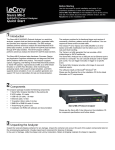
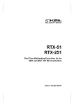
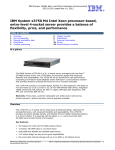
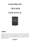
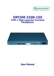
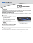
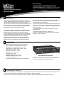
Before Starting
Sierra M6-4
SAS/SATA Protocol Analyzer
Use this document for quick installation and setup. If you
experience problems or need more information, see the
Sierra M6-4 User Manual on the Installation CD or at the LeCroy
web site. For details about the latest software version, see the
Readme file on the Installation CD.
Quick Start
1 Introduction
The Sierra M6-4 SAS/SATA Protocol Analyzer is a serial bus
analyzer, supports host and device emulation, and provides
error injection functionality. The SAS analyzer software
performs serial bus analysis for Serial Attached SCSI (SAS) data
transfers, as well as Serial ATA (SATA) data transfers through
STP data transfers. The SATA analyzer software performs serial
bus analysis for Serial ATA (SATA) data transfers.
The Sierra M6-4 Analyzer helps Hardware, Firmware, Design,
and Application Engineers troubleshoot and diagnose SAS and
SATA problems within their product. The analyzer supports
capture, triggering, and filtering of Serial Attached SCSI packets
or Serial ATA packets. It generates bus traffic as a SAS Initiator
Emulator or a SATA Host Emulator, while monitoring and
analyzing results. SAS supports target emulation, and SATA
supports device emulation. It can run a pattern generator and
support TX Vout on transmitters for test and characterization.
The analyzer provides for bi-directional trigger and capture of
commands, primitives, patterns and all bus conditions. You can
capture all frames or exclude traffic.
The Sierra M6-4 Analyzer has a USB port and an Ethernet port to
connect to a computer. You can cascade analyzer units for higher
port counts. You can trigger manually or put the trigger condition
on a specific event.
The Sierra M6-4 Analyzer provides a full range of views and
statistical reports.
The software installs on Microsoft® Windows® XP.
Please see the Readme file on the installation CD for the latest
information on PC requirements.
2 Components
The analyzer package includes the following components:
•
1 Sierra M6-4 Analyzer identified in the packing list
•
1 Mini-SAS to 4-x1 SATA straight cable, 1 meter
•
1 Mini-SAS to 4-x1 SATA crossover cable, 1 meter
•
2 mSAS to mSAS cables, 1 meter
•
2 mSAS to SAS x4 cables, 1 meter
•
1 USB A-B 2.0 cable, 1.8 meter
•
1 Ethernet cable, 10 feet
•
1 10-position ribbon cable, 6 inches
•
1 SMB RA to SMB RA cable, 6 inches
•
1 Three-Prong AC power cord
•
1 Installation CD ROM with software and documentation
Sierra M6-4 Protocol Analyzer
Please see the Sierra M6-4 User Manual on the installation CD
for component specifications and further details.
3 Unpacking the Analyzer
Inspect the received shipping container for any damage. Unpack the container and account for each of the system components listed on
the accompanying packing list. Visually inspect each component for absence of damage.
In the event of damage, notify the shipper and LeCroy Corporation. Retain all shipping materials for shipper’s inspection.
4 Front Panel Description
1
4
2
3
5
7
6
8
9
Features
1SPEED
The Analyzer has the following features on the front:
•
LED Indicators for I1-T1, I2-T2, I3-T3, and I4-T4 [1]
•
TRIGGER
or for trigger
•
ERROR
or for error
•
LINK
or for link
•
SPEED
or for speed level1
•
FRAME/OOB
or for OOB or traffic2
•
Power Switch (0/1) [2]
•
External Trigger Input (TRIG IN) [3]
•
External Trigger Output (TRIG OUT) [3]
•
Initiator mini-SAS connector [4]
•
Target mini-SAS connector [5]
•
Expansion In/Out data ports and Clock In/Out connectors [6]
•
Status and Configuration LCD Display [7]
•
USB Port for host connectivity [8]
•
Ethernet Port for network connectivity [9]
The orange LEDs for SPEED illuminate as follows:
LEDs
Speed
1.5G
3.0G
6.0G
2
Initiator
Off
On
On
Target
Off
Off
On
FRAME/OOB LEDs
The green LEDs for FRAME/OOB illuminate as follows:
•
Before the link is established, illuminates during the
OOB sequence.
•
After the link is established, indicates traffic on the bus.
5 Expansion Module Connections
The Analyzer provides cascading features through the
Expansion Module via the following connectors:
•
Expansion In/Out connectors [10]
•
Clock In/Out connectors [11]
Expansion
In
Out
Warning:
Do not open the enclosure. No operator
serviceable parts are inside.
Clock
In
Out
6 Installing the Software
Important! Do not connect Sierra M6-4 to your host system until software installation is complete.
1.
Insert the Installation CD ROM into the CD drive on the host machine. The installation automatically starts setup, unless Auto Run is
off. In that case, select the CD ROM from “My Computer” and click Setup.
After the warning to close all other programs and before starting the installation, the Install component selection opens.
2. Select components for installation.
3. Click Next to complete the installation. The Sierra M6-4 software installs on the PC hard disk.
4. Restart the computer before using the software.
Note: If you get an error message during installation of the drivers, consult your system administrator.
7 Setting Up and Connecting
Note: You must install the software before connecting the
analyzer to the host machine for the first time.
To set up the analyzer:
1. Connect the analyzer to a 100V–240V, 50Hz–60Hz, power
outlet and turn on the Power switch.
At power on, the analyzer will go through initialization as
shown on the LCD display.
2. Connect the USB cable between the Sierra M6-4 USB port
and a USB port on the Host PC. The host PC operating
system detects the analyzer and driver files.
3. Connect the analyzer to Initiator and Target:
When using Sierra as a Host Emulator, connect from Target
to hard drives using an iPass to SATA octopus Straight
cable.
When using Sierra as a Device Emulator, connect from
Initiator to HBAs using an iPass to SATA octopus
Crossover cable.
When connecting between a HBA and a disk drive, use
a crossover Mini-SAS (iPASS) from the initiator port on
the Sierra to Mini-SAS or SAS4X cable depending on
the HBA connector, and a Mini-SAS from the target
port to SATAx4, connecting the SATA connector to the
disk drive.
For an illustration of the cabling, see the Introduction chapter
of the Sierra M6-4 User Manual.
Analyzer
Cascading
You can use cascading of analyzer units for higher port
counts, by daisy chaining the units through the provided
Expansion and Clock In/Out interfaces on the analyzer front.
For expansion, see the Introduction chapter of the
Sierra M6-4 User Manual.
HBA
Hard Drive
8 Connecting via Ethernet
The Ethernet connection can have any of these configurations:
Connecting to a Network using a Hub, Switch, GigE interface, or Similar Device
When connected to a network, the analyzer must communicate with the DHCP server to establish a connection. The DHCP server
continually sends the next available IP address to the analyzer until the software starts.
Note: To connect using a different subnet or for remote operation, see the Introduction chapter of the Sierra M6-4 User Manual.
Connecting to a Host Computer using a Hub, Switch, GigE interface, or Similar Device
When connected to the host machine using a hub, switch, GigE interface, or similar device, the Analyzer must communicate with the
host computer to establish a connection. The host computer continually broadcasts the next available IP address to the Analyzer, until
the software starts.
IP_Address: When you start the software, the Internet Protocol (TCP/IP) Properties dialog may prompt you to
automatically use the offered IP address or to assign a specific IP address. (The assigned IP address must be on the same
network segment as the host computer.)
The software searches for all analyzers connected to the network and displays a list of available units in the Find Devices dialog. After
you select a unit, the software assigns the IP address to the selected unit, completing the connection, then launches the software.
Connecting Directly to the Host Computer using a Crossover Cable
Connect Sierra M6-4 to the Host PC using a crossover cable.
9 Starting the Application
To launch the software, double-click the SAS or SATA Icon in the Program Manager Window. The first time you run your software, the
software displays the Device Selection dialog. Select an interface and click OK to display the software
Operating in Simulation Mode
The system operates in Simulation Mode by default, if the software detects no hardware. However, you can operate in Simulation Mode
directly, without installing the Analyzer hardware. To operate without hardware, select Hardware Not Installed (Simulation Mode) in the
Device Selection dialog box and click OK.
To start using the protocol analyzer and software, see the Protocol Analyzer chapter of the Sierra M6-4 User Manual.
10
Running the Software and Hardware
The Sierra M6-4 application has the LeCroy SAS Protocol Suite and the LeCroy SATA Protocol Suite.
Protocol Analysis
To use the software for protocol analysis, first select File > New > Protocol Analyzer for a new project protocol analysis file: .sac for
SAS or .stc for SATA. (You can also open a .scs SAS Sample file or .sts SATA Sample file from the Examples folder.
1. In Easy Mode, on the Capture tab, select to capture Everything or Pattern. For Pattern, select a Pattern. You can exclude patterns
and frames. You can use different patterns for pre-trigger and post-trigger.
2. In Easy Mode, on the Trigger tab, select the trigger type. For Pattern, select the pattern.In Easy Mode, on the Settings tab, select
trigger position and memory use.
3. Change the Analyzer settings if necessary. Change the port Speed if necessary.
4. Use Advanced Mode only after you become familiar with the hardware and software and have special needs.
Protocol Analyzer Initiator Emulator or Host Emulator
To use the software for protocol analysis to generate host traffic, first select File > New > Protocol Analyzer Initiator Emulation or
Protocol Analyzer Host Emulation for a new project Pattern Generator file: .ppf for a dual-role file or .spg for a single-role file.
1. In Easy Mode, on the Initiator Emulator or Host Emulator tab, insert instances of ATA, SCSI, TASK, SMP, Frame, or Event. Select
the type of each from the drop-down lists. You can also loop, go to, wait, delay, if...then, and stop.
2. In Easy Mode, on the Capture tab, Trigger tab, and Settings, follow the steps for Protocol Analysis.
3. In Easy Mode, on the Initiator Setting or Host Setting tab, select the port and speed. Select to run the Pattern Generator or Initiator
Emulator or Host Emulator.
Target Emulator or Device Emulator
To use the software as a target or device emulator, first select File > New > Target Emulator or Device Emulator for a new project .std
Target Emulator file or .sde Device Emulator file.
1. In the Pages tab, change settings for the supported pages if necessary.
2.
In the Error Injection tab, select General periodic errors, Identify frames, Connection Management open and close connection errors,
SAS Commands and events errors, ATA Commands errors, or SATA Signature content.
3. In the Settings tab, select addresses, sizes, times, and ports, if necessary.
To change viewer options and see more detail about operation, see the Introduction chapter of the Sierra M6-4 User Manual.
LeCroy Customer Support
Online Download
Trademarks and Servicemarks
LeCroy, Catalyst, and Sierra M6-4 are trademarks
of LeCroy Corporation.
Microsoft and Windows are registered trademarks
of Microsoft Inc.
Periodically check the LeCroy Protocol Solutions
Group web site for software updates and other
support related to this product. Software updates
are available to users with a current Maintenance
Intel and Pentium are registered trademarks of
Intel Corporation.
AMD Duron and AMD Athlon are trademarks of
Advanced Micro Devices, Inc.
All other trademarks are property of their
Copyright © 2008 by LeCroy Corporation. All rights reserved.
Part Number: 916155-00
This document may be printed and reproduced without additional permission, but all copies should contain this copyright notice.