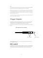
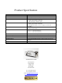
1
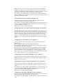
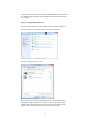
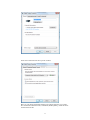
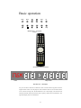
Red Reference MK III CD Player 1 Contents Red Reference MK III CD Player .................................................3 Product Description .......................................................................3 Inventory .......................................................................................3 When setting up .............................................................................4 Safety Warnings ............................................................................5 AC Power connection....................................................................6 AC Connector and Switch .............................................................6 Powering up...................................................................................6 Powering down - long-term...........................................................6 Powering down - short-term ..........................................................6 Connecting your equipment ..........................................................7 Coaxial digital output ....................................................................8 AES/EBU digital outputs ..............................................................9 Optical digital output ...................................................................10 Wordclock input ..........................................................................11 Digital inputs ...............................................................................11 Using USB HD Digital Audio………………………………….12 Balanced analogue outputs…….……………………………….19 Unbalanced outputs .....................................................................19 Everyday use of your Red Reference ..........................................20 Basic operation ............................................................................21 Status display and function .........................................................22 CD Operation ..............................................................................24 Advanced functions .....................................................................25 Trigger Outputs ...........................................................................26 Product Specification ..................................................................27 2 Red Reference Mk III CD Player Thank you for buying a Chord Electronics product. Before you start to enjoy your CD player, please take a couple of minutes to read how to connect your audio equipment and loudspeakers and how to maximise your listening experience. Product Description Building on the success of the RED Reference CD player the Mk III version now has the latest technological updates and has been revised to include a 24bit,192KHz capable USB input and a new motorised door mechanism. With stunning looks and state of the art design the RED utilises ground breaking technology to give the most accurate reproduction of compact disc that can be obtained. With internal 176.4KHz upsampling data transfer, selectable RAM buffer clock retiming and now 18000 tap length filtering the RED earns its reference status in the Chord range. The Red Reference Mk III is a truly unique product. As a standalone CD player it is able to deliver the best reference CD playback. The addition of digital inputs and outputs also gives it the ability to act as both a CD transport and DAC for other audio components making it completely versatile. Inventory As well as your Red Reference and this user manual, you should also have received the following items. 1. Red Reference remote control 2. Power cord 3. Chord guarantee registration card 4. HD USB Cable 5. CD lift 6. Optical Cable 3 When setting up To ensure that your Red Reference works efficiently and safely, please pay particular attention to the following issues. ventilation Your Red Reference should have at least 5cm of clear space all around it to ensure a free flow of air at all times. We do not recommend that you place Red Reference directly on a carpet. AC lead and plug All Chord equipment comes supplied with the correct power lead and plug. This should be used at all times. if you need to fit a plug for UK/Europe Connect the blue wire to the neutral terminal Connect the brown wire to the live terminal Connect the yellow/green wire to the earth terminal if you need to fit a plug for US/Canada Connect the white wire to the neutral terminal Connect the black wire to the live terminal Connect the green to the earth terminal earthing issues in Europe In some European countries a hum may occur if your Red Reference is connected to mains sockets that do not have an earth. If this is the case please ensure that: 1. Your transport is connected via a multi-way mains block, which contains an earth point at each socket outlet. This is to ensure that the chassis metalwork of each item is connected together. 2. We recommend that an earthing method for your building be implemented. 3. Use the connecting points on your Chord unit and connect to an available earth point. 4 Safety Warnings It is important that your Red Reference is earthed at all times via its own mains lead. Failure to do this may be hazardous. The power supply components within the transport are designed to operate at lethal voltages and energy levels. Circuit designs that embody these components conform to applicable safety requirements. Precautions must be taken to prevent accidental contact with power-line potentials. Do not connect grounded test equipment. Caution: This product employs a laser that emits both visible and invisible radiation. Removal of the top cover or tampering with any of the enclosed electronics may result in exposure to hazardous levels of laser radiation that could cause eye damage. To prevent injury this product should be returned for qualified service to Chord Electronics Ltd. There are no user serviceable parts within the Red Reference CD player. Unauthorised tampering or dismantling of this product will invalidate the warranty and could cause injury. 5 AC Power connection The AC power connector of Red Reference is at the back of the unit. Plug the female end (socket) of the power cord into the power connector of the transport, and the male end(plug) of the power cord into AC wall socket or AC extension socket. The Red Reference CD player features a universal voltage high frequency power supply and will operate automatically from 65V to 260V AC, 50 or 60Hz. For optimum operation it is recommended that the Red Reference is connected directly to the wall socket via the power cord provided. AC Power Switch AC Connector IEC 10A EARTH AC Connector and Switch Powering up Press the top of the power switch labelled „I‟. Red Reference will now power up. The Red Reference features a dual display system showing both system status and disc information. The red multi function display will read „CHORD‟ followed by the status information showing input, buffer, frequency settings and lock information. If Red Reference has no disc loaded, the top panel display with read “NO DISC”; if a disc has been loaded then the number of tracks and length of the CD will be shown. Please allow a short time for Red Reference to read the disc‟s Table of Contents (TOC). During this time the display will indicate “-- ----“ Powering down - long-term 1. Press the STANDBY button on the remote to put Red Reference into STANDBY. 2. Press the right-hand side of the power switch labelled „O‟. Powering down - short-term For everyday use there is no need to power Red Reference down completely. Press the STANDBY button on remote to put Red Reference into its Standby mode. The audio circuits remain active in this mode. 6 Connecting your equipment Right output RCA–phono XLR Right output XLR Left output AES/EBU Input Left output RCA-phono Optical Input HD USB Input S/DIF2 OUTPUT OPTICAL OUTPUT AES/EBU OUTPUT 2 AES/EBU OUTPUT 1 WORDCLOCK INPUT Red Reference - rear panel connections All the input and output connections of Red Reference are situated on the rear panel of the transport. Red Reference has three types of digital output; Optical, Coaxial and AES/EBU, three types of digital input optical, USB HD and AES/EBU and both balanced and unbalanced analogue outputs. In addition to the standard digital outputs, a special Dual Data output provides an upsampled digital output at 176.4KHz. Connection to both AES/EBU is required for this mode. Please note:- When using Dual Data mode with two cables please set the operating frequency to 176KHz via the front panel. 7 Coaxial digital output SPDIF OUTPUT Red Reference - coaxial connection Red Reference has one SPDIF output as shown above. This outputs digital audio data from any CD playing. All coaxial connections use BNC connectors with 75ohm impedance. Although less common than RCA-phono digital connectors, BNC connectors exhibit consistent impedance behaviour and are essential for the correct transfer of digital audio data. If your digital-analog converter only has RCA-phono coaxial digital inputs, it is worth having a cable made by a specialist manufacturer. Please avoid RCA-BNC adaptors as they will undoubtedly impair the sound quality. In all cases a correctly screened cable should be used. Frequency Settings The output frequency can be set via the front panel to 44KHz or 88KHz. If you select the 176K option the output will remain at 88KHz. 8 AES/EBU digital outputs AES/EBU OUTPUT 1 AES/EBU OUTPUT 2 For installations that require a long run of cable between the transport and digital-analog converter we would recommend using a balanced AES/EBU connection. The AES/EBU will output digital audio data from any CD playing and can either be used as two identical outputs or combined as one 176.4KHz dual data output. Frequency settings When the front panel frequency switch is set to 176K, the AES/EBU outputs send the Dual Data output as outlined in the previous section. This may be useful when using Red Reference with certain high-resolution D-A converters. When the frequency switch is in the 88K position, each AES/EBU output sends data at 88.2kHz; when in the 44K each output sends at 44.1kHz. Output 44K 88K 176K AES/EBU 1 44.1kHz 88.2kHz 176.4kHz right AES/EBU 2 44.1kHz 88.2kHz 176.4kHz left 9 Optical digital output OPTICAL OUTPUT The optical digital output uses a standard TOSlink connection and can be used with DAC64 and several other digital to analogue converters. This outputs digital audio data from any CD playing. In particular an optical connection can be very useful in the prevention of earth loops, as there is no electrical connection between two products in a system. This may be required when combining Red Reference with products from other manufacturers. Frequency settings Frequency switch 44K 88K 176K Optical output 44.1kHz 88.2kHz 88.2KHz Red Reference has one optical digital output so it is not possible to use the Dual Data facility over optical. 10 Wordclock input WORDCLOCK INPUT A dedicated wordclock input may be required in professional recording and broadcast applications, generally wordclock outputs are not found in domestic audio products. As Red Reference is a reference-grade CD player, it is very likely that our Professional Audio customers will use it as a CD source and so may need to synchronise it within a larger digital system. The wordclock input operates at 44KHz only and automatically switches when a signal is connected. Digital inputs The Red Reference comes equipped with three different types of digital inputs, allowing compatibility with virtually any digital audio source equipment. Digital audio source equipment includes CD transports, DVD players and Mini Disc players and now USB computer connection. The digital inputs consist of one AES balanced XLR input (XLR), one Plastic Fibre Optical TOSLink input (OPT) and one 24 bit, 192KHz USB input (USB). These inputs can be selected via the I/P button on the front panel and will output analogue audio from both the balanced and unbalanced connections. AES/EBU Input Optical Input HD USB Input 11 Using USB HD Digital Audio Connection to the host computer Connect the Red Reference to the host computer by inserting the supplied USB lead into any available USB 2.0 socket. To support 192KHz the USB socket on the computer must be USB 2.0 or above. Once connected insert the other end of the supplied cable into the Red Reference making sure that the red dots are aligned and pointing upwards. If a driver hasn‟t been installed on your computer, an automatic driver installation wizard may appear. Note: If you want to avoid the automatic driver installation, please connect the Red Reference to the computer after manually installing the driver. Driver installation The drivers for Red Reference are available on the supplied CD. Windows drivers are contained in zip files, Mac drivers are contained in dmg files. For Windows XP use chordxp.zip, for Windows Vista or Windows 7 use chordwin7.zip. For the Apple Mac operating systems the dmg files are for OS 10.4(ChordUsb_148104.dmg), 10.5(ChordUsb_148105.dmg) or the latest Snow Leopard 10.6(ChordUsb_148106.dmg). If you have lost the CD please download drivers at www.chordelectronics.co.uk on the QBD76HD product page. Installing the driver on a Windows PC Create a temporary folder on the hard disk of your computer (this can be on your desktop). Double-click on the zip file contained on the CD to open it. Select and drag all files in the temporary folder, this will automatically unzip all the files. Automatic installation Connect Red Reference to the PC. Following the negotiation process, the driver installation wizard is automatically launched. Click on the button to proceed. Choose automatic installation (as recommended) and proceed to next step. Indicate the folder where you have previously unzipped the driver and proceed to installation. Click on Continue. The installation will proceed to the end. You may get warning messages indicating that the driver is not digitally signed - just click yes to continue installation. Click on Finish to complete the driver installation. Note: the wizard appearance and the guided installation procedure may slightly vary from XP to Vista to Windows 7. Manual installation Sometimes it is necessary or advisable to install the driver manually. The installation package offers two installation utilities, “setup32.exe” and “setup64.exe”. The former is for 32 bit operating systems, while the latter is for 64 bit operating systems. Without connecting Red Reference to the PC, double-click on either “setup64.exe” or “setup32.exe”, depending on your operating system: the driver will automatically be installed on your PC. Installing the driver on a Mac Double-click on the zip file to open it. It contains a single dmg file. Extract it 12 from the zip and double-click on it to open it. It only contains a pkg file. Double click on it to start driver installation. Click on the Continue button. Select “Install for all users”, then click on Continue button. You‟ll be asked to type in the administrator password. After doing that, the installation process will continue and you‟ll be asked for a confirmation to continue the process up to the computer restart. Click on Continue Installation button. The installation will continue until the final window appears showing the successful installation of the driver. Click on Restart button to complete the installation process. Unistalling the driver ( Windows PC only ) Sometimes it is necessary to uninstall the driver to roll back to a previous version. Uninstall is a quite simple procedure which depends on the operating system and the way the driver was installed. Uninstalling the driver on a Windows-based PC after installation with setup32.exe or setup64.exe Go to the control panel and launch the program and features (add/remove programs) utility. Look for the Chord Async USB 44.1kHz–192kHz driver item in the list. Double-click on it to launch uninstalling. Manually uninstalling the driver on a Windows-based PC Connect Red Reference to the PC. Go to the control panel and launch the “System” utility, then select Hardware tab. Open the Device Management window. You will find Chord Async USB 44.1kHz–192kHz device listed under Audio, Video and Game controllers. Right-click to access the available actions. Select “Uninstall”. Configuring the computer to use Red Reference USB input Configuring a PC with Windows XP A PC with Windows XP can use Red Reference in two different ways: Direct Sound (DS) and Kernel Streaming (KS). Direct Sound is suitable for players which can‟t operate in Kernel Streaming mode (such as Windows Media Player and iTunes) or for Internet streaming. Kernel Sound can be chosen (for better performance) with players which can operate in Kernel Streaming mode (such as FooBar, Winamp, Monkey Media, JRiver). Please note that in Windows XP there is no direct sample rate setup in the audio settings panel. Sample rate can only be selected in Kernel Streaming mode with an appropriate player. Configuring for Direct Sound with Windows XP Connect Red Reference to your PC. Then, go to the Control Panel and launch the Sound and Audio Peripherals utility. Select the Audio tab. In the Predefined Peripheral drop-down menu of the Playback area, select “Chord Async USB 44.1kHz–192kHz” 13 Then, select the “Voice” Tab. Again, select “Chord Async USB 44.1kHz– 192kHz” in the drop-down menu of the Playback area. Click on OK button. Please be advised that even if the Red Reference peripheral is listed as “kernel streaming”, it will operate in Direct Sound mode when listed here. From now on, unless Red Reference is disconnected or settings are changed again, Red Reference is the audio peripheral all audio programs will use when operating in direct sound mode. Configuring for Kernel Streaming with Windows XP Kernel Streaming has no standard setting in Windows XP. KS must be selected in the specific player you choose to use. For example, when using FooBar, with Red Reference connected to the PC, go to the File/Preferences/Playback /Output tab and select “Chord Async USB 44.1kHz–192kHz” as output device. Other players will require different settings. Using Red Reference in both Kernel Streaming and Direct Sound mode When Red Reference is selected as an audio peripheral, it‟s possible to use it in both Kernel Streaming mode and Direct Sound mode. When using it in KS mode, it is necessary that no other application accesses Red Reference in DS mode. If this happens, Windows XP‟s Kernel Mixer takes control of Red Reference‟s driver and from then on, no KS application can access the Red Reference unless the PC is restarted or Red Reference connection to the PC is cycled. Configuring a PC with Windows Vista or Windows 7 A PC with Windows Vista or Windows 7 can use Red Reference in three different ways: Direct Sound (DS), Kernel Streaming (KS) and WASAPI. DS is suitable for players which can‟t operate in Kernel Streaming mode or with WASAPI or for Internet streaming; KS can be chosen (for better performance) with players which can operate in Kernel Streaming mode (such as FooBar, Winamp, Monkey Media, JRiver). WASAPI (Windows Audio Standard API) is a standard interface for audio players which gives you the same performance of KS with applications which can‟t operate in KS mode, at the cost of higher CPU load. Configuring for Direct Sound with Windows Vista or Windows 7 Open control Panel and select Hardware and Sounds. Under Audio, click on Manage Audio Devices. Set Chord Async USB 44.1kHz–192kHz as default device. Then, click on OK. Configuring for Kernel Streaming with Windows Vista or Windows 7 As for Windows XP, Kernel Streaming has no standard setting in Windows Vista and Windows 7. KS must be selected in the specific player you choose to use. For example, when using FooBar, with Red Reference connected to the PC, go to the File/Preferences/Playback /Output tab and select “Kernal Streaming Chord Async USB 44.1kHz–192kHz” as output device. Other players will require different settings. Configuring for WASAPI with Windows Vista or Windows 7 Similar to Kernel Streaming, WASAPI cannot be directly accessed. WASAPI must be selected in the specific player you choose to use. For example, when using FooBar, with Red Reference connected to the PC, go to the 14 File/Preferences/Playback /Output tab and select “WASAPI: Chord Async USB 44.1kHz–192kHz” as output device. Other players will require different settings. Configuring Mac OS X Open the System Environment Settings from the Start menu. Open the Sound options from the System Environment settings. Select the Output tab and confirm the Chord Async USB 44.1kHz–192kHz USB audio codec appearance as the default output device. Sample Rate Setup Open the Audio MIDI Settings options (Application – Utility - Set Audio MIDI). Select the Audio Output tab in the Set Audio MIDI. Select the desired sample frequency from the options given. Configuring the player for Kernel Streaming: some examples FooBar To use FooBar in KS mode it is necessary to download the DLL for Kernel Streaming from the FooBar2000 website and install it in the Components subfolder inside FooBar2000 main folder in your hard disk. The DLL can be found at http://www.foobar2000.org/components/view/foo_out_ks. It is a zip folder which contains the DLL. Extract it from the zip and copy to the Components folder. Then, restart FooBar, go to the File/Preferences/Playback/Output window and set parameters. 5.2. Winamp and MediaMonkey These two players are actually the same player with different skins, so they can share the same plug-ins. A freeware plug-in for Kernel Streaming by Steve Monks is available on the Internet (http://www.stevemonks.com/ksplugin/) that can be used to enable Kernel Streaming operation with these players. Download the zip file, extract the dll file and copy it into the Plugins folder inside Winamp main folder. With Red Reference connected, right-click on Winamp and select Display/Select Plug-ins. The Preferences window of Winamp will open. Go to Plug-in/Output and select “Kernel Streaming Output”. Then click on Configure button. Choose Red Reference Kernel Streaming in the output device list. Configuring the player for WASAPI: an example FooBar To use FooBar with WASAPI under Windows 7 it is necessary to download the DLL for WASAPI from the FooBar2000 website and install it in the Components sub-folder inside FooBar2000 main folder on your hard disk. The DLL can be found at http://www.foobar2000.org/components/view/foo_out_wasapi . It is a zip folder which contains the DLL. Extract it from the zip and copy to the Components folder. Then, restart FooBar, go to the File/Preferences/Playback/Output window and set parameters. Sample rate setup for Red Reference (Windows Vista Example) 15 Once the driver software has been installed and the Red Reference connected to a Windows based computer then the digital audio sample rate needs to be set as follows:- Stage 1:- Configuring audio devices Connect the Red Reference to the computer with the supplied USB cable. Run the Windows Control panel and select Hardware and Sound The select „Manage Audio Devices‟ Here you have a list of the connected audio devices. The Red Reference is identified as a digital output device with the „Chord Async USB 44.1kHz192kHz‟ driver installed. Shown at the top of the list here. Right click the digital output and select properties to show the following screen:- 16 Select the Advanced tab at the top of the window Here you can change the default format to the sample frequency you require. We recommend 2 channel 24 bit, 192000 Hz (Studio Quality). Click the arrow and select the format. 17 Then click OK It is also a good idea at this stage to set the Digital Output as the default sound output device. Highlight Digital Output as shown then click the Set Default button at the bottom of the page. Click the OK button to continue. Sample rate setup is now complete. 18 Balanced analogue outputs You need to connect the analogue outputs on the back of the Red Reference to a pre-amplifier, which in turn will feed a signal to a power amplifier in order to drive your loudspeakers. There is a pair of balanced XLR outputs, which will drive a 68Ω load. connecting to your pre-amplifier Use the XLR style output connectors to connect the Red Reference to the XLR style input connectors of any model of Chord pre-amplifier. Ensure that you connect the left output on the Red Reference to the left input on the pre-amplifier. Also the right output should be connected to the right input on the pre-amplifier. RIGHT LEFT Unbalanced outputs You need to connect the outputs on the back of your Red Reference to a pre-amplifier, which in turn will feed a signal to a power amplifier in order to drive your loudspeakers. All Chord equipment is designed to be used with balanced connections to maximise audio signal quality. However there is also a pair of unbalanced outputs as well in case your pre-amplifier does not have balanced inputs. connecting to your pre-amplifier Use the phono style output connectors to connect the Red Reference to the phono style input connectors of your pre-amplifier. Ensure that you connect the left output on the Red Reference to your left input on your pre-amplifier. Also the right output on the Red Reference should be connected to the right input on your pre-amplifier. RIGHT LEFT 19 Everyday use of your Red Reference Loading and removing discs Loading the disc OPEN Firstly open the lid using the OPEN button on the front panel. Please note the lid is now fitted with a motorised mechanism that will automatically open and close the lid when the button is pressed. Placing the disc Place the disc gently but firmly in the CD housing so that the centre of the disc sits right on the spindle. Now press the open button to close the lid again . Wait a short time for Red Reference to read the disc Table of Contents before you press Play. Removing discs Using your forefingers, push the disc towards the back of the transport as shown by the arrow above, so that the disc rises gently over the CD spindle. You should now be able to lift the disc out with your thumb. CD SPINDLE Red Reference – cross-section (lid not shown) 20 Basic operation OPEN PROG BUFF I/P FREQ Red Reference – front panel controls Chord System Remote Control TRACK 176K PROGRAM SCAN SHUFFLE A–B TOTAL REM REPEAT 1 PAUSE CD operation Status Red Reference – dual display For your convenience the main CD functions can be accessed from the top panel and on the supplied remote control. For the purposes of the instructions below it does not matter which set of controls are being used. The Red Reference uses a dual display. The left hand side indicates functional status and indicates input, frequency, buffer and lock information. The right hand display shows CD information. 21 TIME Status display and function Using the BUFF, I/P and FREQ buttons on the front panel the Red Reference function can be selected. The status of these functions is indicated on the left hand display. On initial switch on and from standby the display will indicate the current settings. I/P Pressing the input button will change between CD, USB,OPT and XLR functions. When playing a CD select the CD input to output the signal to the analogue connections. If you wish to output a source connected via the XLR, USB or optical digital inputs select XLR, USB or OPT as appropriate. This uses the high quality internal QBD76 decoder to reproduce the analogue signal. CD OPT USB XLR Lock Indication When the internal DAC circuitry receives a valid digital signal from any of the digital inputs CD, USB,OPT or XLR, the display will show LOCK. This will revert back to the frequency setting after a few seconds. LOCK FREQ Pressing the frequency button changes the CD and digital output upsampling frequency between 44.1, 88.2 and 176.4KHz. Please note:- On CD mode when listening to a CD 176K will always be automatically selected. 44K 176K 88K 22 BUFF Pressing the BUFF button changes the RAMbuffer settings. Buffering is a processing operation where the digital input signal is stored in RAM (random access memory) for a period of time before it is passed through the Red Reference DAC circuitry. This period of time allows the Red Reference to analyse the input signal for any errors and to correct them. There are three buffer settings to choose from. These are no buffering, (0BUF), minimum buffering (MIN) and maximum buffering (MAX). The three buffer settings are chosen using the BUFF switch. On the front panel. When using the buffer on minimum or maximum settings there will be a delay to process the digital signal before music is heard. Whenever switching between the different buffer settings there is a delay of approximately 4 seconds before play resumes. 0BUF MAX MIN 23 CD Operation PLAY To play the disc from the beginning, press “Play” ( ). To select a particular track, press the track number eg. 6, followed by the “Play” button. STOP To stop the disc, press “Stop” ( ). PAUSE To pause the disc at a particular time, press “Pause” ( ). Play can be resumed by pressing either “Play” or “Pause”. To select the next or previous track, press Next Track ( ) or Previous Track ( To search through the disc in either direction, hold down Search Back ( Forward ( ). ) or Search ) To speed up the search, press the “FAST” key once while Search Back or Search Forward are held down. The FAST key has no effect if pressed on its own. STANDBY Press the STANDBY button to put Red Reference into Standby and to wake it up again. TIME Normally the transport will display the time elapsed on the track you are playing. Press „TIME‟ once and it will now show total time elapsed on the disc and display TOTAL; press „TIME‟ again and the transport will show the time remaining on the disc and display TOTAL REM. Press TIME once again to return the display to normal. 24 Advanced functions Program Mode - Programming a track selection – Press the track number (eg. 7) followed by the „PROG‟ button, then the next track (eg. 4) followed by PROG, and so on until all tracks have been programmed. To play your selection, press PLAY. On the system remote control the program button is the central OK button. If you press the PROG button before entering a track number, an error message “ERR” will appear on the top panel display. When in program mode, PROGRAM will be shown on the display. The Previous Track, Next Track and Search functions will all work as normal, but will move around between the tracks you have programmed. The STOP button, if pressed once, returns the transport to the beginning of the programmed selection. If you press STOP a second time then you will exit program mode and your track selection will be lost. REPEAT While the disc is playing, press “REPEAT‟ once to repeat the whole disc. REPEAT will be shown on the front panel display. Previous Track, Next Track and Search will work as normal in this mode. Press „REPEAT‟ again to repeat a particular track; REPEAT1 will now be shown on the display. If you press Previous or Next track; if you Search past the beginning or end of the track; or if you press STOP, you will exit repeat mode. Pressing „REPEAT‟ for a third time will exit repeat mode. RANDOM Press „RANDOM‟ and the transport will play tracks in random order until all tracks have been played. RANDOM will be shown on the top panel display. If you want random play to continue indefinitely, press „RANDOM‟ and then „REPEAT‟. Play will now continue until you press STOP. Note that the Random control on the Red Reference remote is marked “SHUF”. 25 A-B This function plays a particular section of your choosing in a loop between points A and B. The selected section can be any length from a few seconds to several tracks. When the disc is playing, press „A-B‟ to set the start point A, then let the disc continue to your chosen end point and press „A-B‟ again to set point B. The transport will now play only the information between points A and B, then back to A and so on. A-B will also appear on the top panel display. To exit this mode, press „A-B‟ for a third time and the disc will continue playing as normal, or press STOP to stop the disc. Trigger Outputs The Red Reference features two trigger outputs that can be used to remotely trigger other Chord equipment. The external trigger should be connected via a standard 1/8th inch / 3.5mm (mono or stereo) jack plug to the socket fitted to the rear of the unit. The Red Reference should be switched off, the trigger lead inserted, then the unit switched back on. The connections are as follows: 0V / Ground The tip of the plug is the +5V to +12V dc connection, the centre and rear connection are the 0V or ground connection. IR Control The third socket on the rear panel connects to the IR remote control receiver within the Red Reference. When using room control systems you can connect the remote signal discretely to this socket rather than using an external IR repeater stuck to the front panel display. 26 +5V to +12V c. Product Specification HARMONIC DISTORTION SIGNAL TO NOISE RATIO CHANNEL SEPARATION DYNAMIC RANGE SWITCHABLE DIGITAL INPUTS DIGITAL OUTPUTS ANALOGUE OUTPUTS SWITCHABLE RAM BUFFER WORD CLOCK INPUT SAMPLE FREQUENCIES OUTPUT MAX OUTPUT IMPEDANCE POWER SUPPLY DIMENSIONS IN MM WEIGHT < -107 dB (1kHz, 24-Bit @ 44.1KHz Sample Frequency) > 120dB > 125dB @ 1KHz (> 100dB @ 22KHz) 122dB 1 x AES Balanced XLR Input 1 x Plastic Optical Fibre (TOSLink) 1 x HD USB Input 192KHz capable 1 x BNC coax 1 x Plastic Optical Fibre (TOSLink) 2 x AES Balanced XLR (Can be configured for dual data 176.4KHz) 2 X RCA Phono 2 X BALANCED XLR Position 1 – No Buffering Position 2 – Minimum Buffering Position 3 – Maximum Buffering 44.1KHz Word Clock Synchronisation via BNC input 32KHz – 176.4KHz 6V rms. Balanced. 3V rms. unbalanced 75 (short circuit protected) Universal Input High Frequency Supply operates from 65V to 265V AC 420 x 140 x 325mm (Width x Height x Depth) 14Kg Chord Electronics Limited The Pumphouse Farleigh Bridge Farleigh Lane East Farleigh Kent ME16 9NB Tel: +44 (0)1622 721444 Fax: +44 (0)1622 721555 Email: [email protected] http://www.chordelectronics.co.uk 27