1
UM1021
User manual
STM32F105/107xx USB Host library
Introduction
The STM32F105/7 USB host library is intended to provide a framework for USB host
applications development.
The library stands on top of the STM32F105/7 USB OTG peripheral low-level driver. It
implements the necessary software blocks that aim to facilitate the developement of USB
host applications.
The STM32F105/7 USB host stack library supports the following two USB standard class
applications:
■
Mass Storage Class (MSC) for accessing USB flash pendrives
■
Human Interface Device (HID) class for keyboard and mouse devices
November 2010
Doc ID 18153 Rev 1
1/31
www.st.com
Contents
UM1021
Contents
1
Folder organization of the USB host package . . . . . . . . . . . . . . . . . . . . 6
2
USB host library architecture . . . . . . . . . . . . . . . . . . . . . . . . . . . . . . . . . . 8
2.1
Library block diagram organization . . . . . . . . . . . . . . . . . . . . . . . . . . . . . . 8
2.2
Description of the library core . . . . . . . . . . . . . . . . . . . . . . . . . . . . . . . . . . 9
2.3
3
4
Core state machine . . . . . . . . . . . . . . . . . . . . . . . . . . . . . . . . . . . . . . . . . 9
2.2.2
Device enumeration . . . . . . . . . . . . . . . . . . . . . . . . . . . . . . . . . . . . . . . . 10
2.2.3
Control transfer state machine . . . . . . . . . . . . . . . . . . . . . . . . . . . . . . . . 11
2.2.4
USB I/O requests module . . . . . . . . . . . . . . . . . . . . . . . . . . . . . . . . . . . 11
2.2.5
Host channels control module . . . . . . . . . . . . . . . . . . . . . . . . . . . . . . . . 12
Class drivers . . . . . . . . . . . . . . . . . . . . . . . . . . . . . . . . . . . . . . . . . . . . . . . 13
2.3.1
USB Mass Storage Class (MSC) driver . . . . . . . . . . . . . . . . . . . . . . . . . 13
2.3.2
USB Human Interface Device (HID) class driver for mouse and
keyboard devices . . . . . . . . . . . . . . . . . . . . . . . . . . . . . . . . . . . . . . . . . . 17
Library user API and callback functions . . . . . . . . . . . . . . . . . . . . . . . . 20
3.1
Library user API . . . . . . . . . . . . . . . . . . . . . . . . . . . . . . . . . . . . . . . . . . . . 20
3.2
User callback functions . . . . . . . . . . . . . . . . . . . . . . . . . . . . . . . . . . . . . . 20
3.2.1
Class callback functions . . . . . . . . . . . . . . . . . . . . . . . . . . . . . . . . . . . . . 20
3.2.2
Class-independent callback functions . . . . . . . . . . . . . . . . . . . . . . . . . . 22
Demo firmware . . . . . . . . . . . . . . . . . . . . . . . . . . . . . . . . . . . . . . . . . . . . 25
4.1
4.2
4.3
2/31
2.2.1
Mass storage class demo . . . . . . . . . . . . . . . . . . . . . . . . . . . . . . . . . . . . . 25
4.1.1
Software initializations . . . . . . . . . . . . . . . . . . . . . . . . . . . . . . . . . . . . . . 25
4.1.2
Mass storage device enumeration . . . . . . . . . . . . . . . . . . . . . . . . . . . . . 25
4.1.3
Accessing mass storage device content . . . . . . . . . . . . . . . . . . . . . . . . 26
4.1.4
Flash pendrive tests . . . . . . . . . . . . . . . . . . . . . . . . . . . . . . . . . . . . . . . . 26
HID mouse and keyboard demos . . . . . . . . . . . . . . . . . . . . . . . . . . . . . . . 27
4.2.1
Initializations . . . . . . . . . . . . . . . . . . . . . . . . . . . . . . . . . . . . . . . . . . . . . 27
4.2.2
Mouse or keyboard device enumeration . . . . . . . . . . . . . . . . . . . . . . . . 27
4.2.3
Mouse demo . . . . . . . . . . . . . . . . . . . . . . . . . . . . . . . . . . . . . . . . . . . . . 28
4.2.4
Keyboard demo . . . . . . . . . . . . . . . . . . . . . . . . . . . . . . . . . . . . . . . . . . . 28
Demo footprints . . . . . . . . . . . . . . . . . . . . . . . . . . . . . . . . . . . . . . . . . . . . 28
Doc ID 18153 Rev 1
UM1021
Contents
5
Known limitations . . . . . . . . . . . . . . . . . . . . . . . . . . . . . . . . . . . . . . . . . . 29
6
Revision history . . . . . . . . . . . . . . . . . . . . . . . . . . . . . . . . . . . . . . . . . . . 30
Doc ID 18153 Rev 1
3/31
List of tables
UM1021
List of tables
Table 1.
Table 2.
Table 3.
Table 4.
Table 5.
Table 6.
Table 7.
Table 8.
Table 9.
Table 10.
Table 11.
Table 12.
Table 13.
Table 14.
Table 15.
Table 16.
Table 17.
4/31
Core files. . . . . . . . . . . . . . . . . . . . . . . . . . . . . . . . . . . . . . . . . . . . . . . . . . . . . . . . . . . . . . . . 7
Class files . . . . . . . . . . . . . . . . . . . . . . . . . . . . . . . . . . . . . . . . . . . . . . . . . . . . . . . . . . . . . . . 7
Device enumeration requests . . . . . . . . . . . . . . . . . . . . . . . . . . . . . . . . . . . . . . . . . . . . . . . 11
USB I/O requests module . . . . . . . . . . . . . . . . . . . . . . . . . . . . . . . . . . . . . . . . . . . . . . . . . . 12
Host channels control module . . . . . . . . . . . . . . . . . . . . . . . . . . . . . . . . . . . . . . . . . . . . . . 12
Mass Storage Class modules . . . . . . . . . . . . . . . . . . . . . . . . . . . . . . . . . . . . . . . . . . . . . . . 13
MSC core module . . . . . . . . . . . . . . . . . . . . . . . . . . . . . . . . . . . . . . . . . . . . . . . . . . . . . . . . 15
MSC BOT module . . . . . . . . . . . . . . . . . . . . . . . . . . . . . . . . . . . . . . . . . . . . . . . . . . . . . . . 15
MSC SCSI commands . . . . . . . . . . . . . . . . . . . . . . . . . . . . . . . . . . . . . . . . . . . . . . . . . . . . 16
MSC filesystem interface functions. . . . . . . . . . . . . . . . . . . . . . . . . . . . . . . . . . . . . . . . . . . 16
EFSL main API . . . . . . . . . . . . . . . . . . . . . . . . . . . . . . . . . . . . . . . . . . . . . . . . . . . . . . . . . . 17
HID class modules . . . . . . . . . . . . . . . . . . . . . . . . . . . . . . . . . . . . . . . . . . . . . . . . . . . . . . . 17
MSC core module functions . . . . . . . . . . . . . . . . . . . . . . . . . . . . . . . . . . . . . . . . . . . . . . . . 18
Mouse and keyboard intialization & HID report decoding functions . . . . . . . . . . . . . . . . . . 19
Tested flash pendrives . . . . . . . . . . . . . . . . . . . . . . . . . . . . . . . . . . . . . . . . . . . . . . . . . . . . 27
Demo footprints . . . . . . . . . . . . . . . . . . . . . . . . . . . . . . . . . . . . . . . . . . . . . . . . . . . . . . . . . 28
Document revision history . . . . . . . . . . . . . . . . . . . . . . . . . . . . . . . . . . . . . . . . . . . . . . . . . 30
Doc ID 18153 Rev 1
UM1021
List of figures
List of figures
Figure 1.
Figure 2.
Figure 3.
Figure 4.
Figure 5.
Figure 6.
Figure 7.
Figure 8.
Figure 9.
Folder organization . . . . . . . . . . . . . . . . . . . . . . . . . . . . . . . . . . . . . . . . . . . . . . . . . . . . . . . . 6
USB host library block diagram organization . . . . . . . . . . . . . . . . . . . . . . . . . . . . . . . . . . . . 8
Core state machine. . . . . . . . . . . . . . . . . . . . . . . . . . . . . . . . . . . . . . . . . . . . . . . . . . . . . . . . 9
Device enumeration . . . . . . . . . . . . . . . . . . . . . . . . . . . . . . . . . . . . . . . . . . . . . . . . . . . . . . 10
Block diagram organization of the MSC driver . . . . . . . . . . . . . . . . . . . . . . . . . . . . . . . . . . 14
MS device enumeration . . . . . . . . . . . . . . . . . . . . . . . . . . . . . . . . . . . . . . . . . . . . . . . . . . . 25
MS device content access . . . . . . . . . . . . . . . . . . . . . . . . . . . . . . . . . . . . . . . . . . . . . . . . . 26
Mouse demo . . . . . . . . . . . . . . . . . . . . . . . . . . . . . . . . . . . . . . . . . . . . . . . . . . . . . . . . . . . . 28
Keyboard demo . . . . . . . . . . . . . . . . . . . . . . . . . . . . . . . . . . . . . . . . . . . . . . . . . . . . . . . . . 28
Doc ID 18153 Rev 1
5/31
Folder organization of the USB host package
1
UM1021
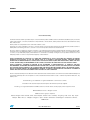
Folder organization of the USB host package
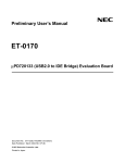
The STM32 USB host library package has the following folder organization:
Figure 1.
Folder organization
STM32_USB_HOST_LIB_PACKAGE
Librairies
CMSIS
STM32_USB_HOST_Library
Class
HID
MSC
Core
STM32_USB_HOST_Driver
STM32F10x_StdPeriph_Driver
Project
USB_HOST_Examples
HID_KBrd_Mouse
MSC
Utilities
STM32_EVAL
STM3210C_EVAL
Third_Party
efsl
The package folders are organized as follows:
6/31
■
Libraries:
– CMSIS: Cortex Microcontroller Software Interface Standard files
– STM32_USB_HOST_Library: USB Host library files
– STM32_USB_HOST_Driver: STM32 USB 2.0 OTG peripheral low-level driver
– STM32F10x_StdPeriph_Driver: STM32 standard peripheral drivers
■
Project:
– USB_HOST_EXAMPLES/HID_KBrd_Mouse : HID mouse and keyboard demo files
– USB_HOST_EXAMPLES/MSC: Mass Storage Class demo files
■
Utilities:
– STM32_EVAL/STM3210C_EVAL : STM3210C_EVAL evalboard functions
(configuration of GPIOs, LCD, clocks,..)
– Third_Party/efsl: EFSL FAT filesystem, used for the mass storage demo
Doc ID 18153 Rev 1
UM1021
Folder organization of the USB host package
File organization of the USB host library
The USB host library folder “STM32_USB_HOST_Library” is composed of two main
subfolders:
■
Core: this folder contains the USB host library core files. Those files implement the
necessary functions, state machines and data structures required for:
– device detection and enumeration,
– USB Control transfer management,
– low-level functions for issuing control, bulk or interrupt USB transactions,
– configuration of the USB host channels.
■
Class: this folder contains the necessary files for USB class management. The USB host
library supports two USB classes:
– MSC: Mass Storage Class
– HID: Human Interface Device class for boot mouse and keyboard devices
The following tables detail the Core and Class files:
Table 1.
Core files
File
Description
usbh_core.c / .h
Implements the core, the device enumeration and the control transfer state
machines
usbh_stdreq.c / .h
USB standard requests needed during device enumeration (USB chapter 9)
usbh_ioreq.c /.h
usbh_hcs.c /.h
usbh_def.h
Table 2.
Class
HID
USB I/O requests: USB transaction requests for control, bulk and interrupt
pipes
USB host channel control (channel configuration, allocation, freeing...)
Definitions used throughout the USB host library
Class files
File
Description
usbh_hid_core.c /.h
HID class management
usbh_hid_mouse.c ./h
HID mouse specific routines
usbh_hid_keyboard.c /.h
HID keyboard specific routines
usbh_msc_core.c /.h
Mass Storage Class management
usbh_msc_bot.c ./.h
BOT “Bulk Only Transport” protocol implementation
usbh_msc_scsi.c /.h
SCSI standard command implementation
usbh_msc_fs_interface.c ./h
Interface with a filesystem for file access operations
MSC
Doc ID 18153 Rev 1
7/31
USB host library architecture
UM1021
2
USB host library architecture
2.1
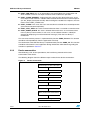
Library block diagram organization
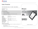
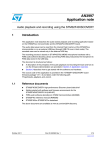
The USB host library has the following block diagram organization:
Figure 2.
USB host library block diagram organization
User application
Library user APIs & callback functions
File
system
USB host library
Core
HID
MSC
Core
state machine
Device
enumeration
Class drivers
Control transfer state machine
USB I/O requests
USB host channels control
STM32 USB OTG peripheral low-level driver
As shown in the above figure, the USB host library is composed of two main parts: the core
and the class drivers.
The library core is composed of five main blocks:
■
core state machine
■
device enumeration
■
control transfer state machine
■
USB I/O requests
■
USB host channels control
For all class-related operations, the core state machine hands over operation to a specific
class driver. In the current release version of the USB host libray, two class drivers - HID and
MSC - are implemented. These class drivers use core layer services for communicating with
the low-level driver.
Both the core and the class drivers communicate with the user application mainly through
defined callback functions.
The various host library blocks are described below.
8/31
Doc ID 18153 Rev 1
UM1021
USB host library architecture
2.2
Description of the library core
2.2.1
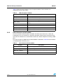
Core state machine
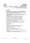
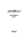
The following figure describes the library state machine:
Figure 3.
Core state machine
Device connection
Event
HOST_ISSUE_
CORE_RESET
Host Initializations
USB Reset Issued
Device disconnection
Event
HOST_IDLE
Device connected &
USB Reset Issued
HOST_DEV_ATTACHED
USB Full/Low speed device attached
HOST_ENUMERATION
Device enumerated
HOST_ERROR_STATE
HOST_CTRL_XFER
HOST_USR_INPUT
User selects to enter
in class operation
HOST_CLASS_REQUEST
End of class
requests calls
Control transfer
HOST_CLASS
Unrecovered error
The core state machine shows 8 states:
■
HOST_IDLE: after host initialization , the core starts in this state, where it polls for a USB
device connection. This state is also entered when a device disconnection event is
detected, and also when an unrecovered error occurs.
■
HOST_ISSUE_CORE_RESET: this state is entered when a device is connected in order
to issue a USB bus RESET.
■
HOST_DEV_ATTACHED: the core enters in this state when a device is attached. When
a full-speed or low-speed device is detected, the state machine moves to the
HOST_ENUMERATION state.
■
HOST_ENUMERATION: in this state, the core proceeds with a basic enumeration of the
USB device. At the end of enumeration process, the default device configuration
(configuration 0) is selected.
Doc ID 18153 Rev 1
9/31
USB host library architecture
UM1021
■
HOST_USR_INPUT: this is an intermediary state which follows the enumeration and
which includes a wait for user input in order to enter in USB class operation.
■
HOST_CLASS_REQUEST: starting from this state, the class driver takes over, and a
class request state machine is called in order to handle all the initial class control requests
(ex: Get_Report_Descriptor for HID). After finishing the needed class requests, the core
moves to the HOST_CLASS state.
■
HOST_CLASS: in this state, the class state machine is called for class-related operation
(non-control and control operation).
■
HOST_CTRL_XFER: this state is entered whenever there is a need for a control transfer.
■
HOST_ERROR_STATE: this state is entered whenever there is an unrecovered error
from any library state machine; in such case, a user-callback function is called (for
example for displaying an unrecovered error message). Then the host library is
reinitialized.
The core state machine process is implemented by function USBH_Process. This function
should be called periodically from the application main loop.
The initalization of the USB host library is implemented by function USBH_init. This function
should be called from the user application during initialization. More details regarding this
function are provided in Section 3.
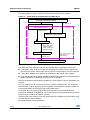
2.2.2
Device enumeration
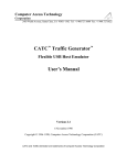
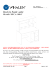
After detecting a full- or low-speed device, the host library proceeds with a basic
enumeration of the device.
The following diagram shows the different steps involved in the device enumeration.
Figure 4.
Device enumeration
Get first 8 bytes of device descriptor
USB reset
Get full device descriptor
Set device address
Get configuration descriptor
Get string descriptors
(MFC, product and serial number)
Set device configuration
10/31
Doc ID 18153 Rev 1
UM1021
USB host library architecture
The enumeration state machine is implemented in library function USBH_HandleEnum,
which is called from the core state machine process.
USBH_HandleEnum function makes calls to the following library routines (implemented in
file usbh_stdreq.c):
Table 3.
Device enumeration requests
Function
Description
USBH_Get_CfgDesc
Get configuration descriptor request
USBH_Get_DevDesc
Get device descriptor request
USBH_Get_StringDesc Get string descriptor request
USBH_GetDescriptor
Generic get descriptor request
USBH_SetCfg1)
Set configuration request
2)
Note:
USBH_SetAddress
Set address request
USBH_ClrFeature
Clear feature request
1
USBH_SetCfg calls select the default configuration (configuration 0)
2
USBH_SetAddress calls set the device address to 0x1.
A user callback will be called at the end of enumeration phase in order to enable the user to
process the descriptor information (such as displaying descriptor data, for example). For
more details, please refer to Section 3.
2.2.3
Control transfer state machine
The control transfer state machine is entered from core or class driver whenever a control
transfer is required. This state machine implements the standard stages for a control
transfer, i.e. the setup stage, the optional data stage and, finally, the status stage.
The control transfer state machine is implemented in function USBH_HandleControl . It is
called from the core state machine process.
2.2.4
USB I/O requests module
The USB I/O requests module is located in the low layer of the core. It interfaces with the
USB low-level driver for issuing control, bulk or interrupt USB transactions.
Doc ID 18153 Rev 1
11/31
USB host library architecture
UM1021
Table 4 shows the main functions in the I/O request module. These functions are
implemented in file usbh_ioreq.c.
Table 4.
USB I/O requests module
Function
2.2.5
Description
USBH_CtlSendSetup
Issue a setup transaction
USBH_CtlSendData
Issue a control data OUT stage transaction
USBH_CtlReceiveData
Issue a control data IN stage transaction
USBH_CtlReq
high level function for issuing a control transfer (setup, data, status
stages)
USBH_BulkSendData
Issue a bulk OUT transaction
USBH_BulkReceiveData
Issue a bulk IN transaction
USBH_InterruptSendData
Issue an interrupt OUT transaction
USBH_InterruptReceiveData
Issue an interrupt IN transaction
Host channels control module
The host channels control module is located in the lower layer of the core, it allows the
configuration of a host channel for a particular operation (control, bulk or interrupt transfer
type) also the allocation of a selected host channel to a device endpoint for creating a USB
pipe.
The main functions for USB channel control module are defined in Table 6. These functions
are implemented in file usbh_hcs.c.
Table 5.
Host channels control module
Function
12/31
Description
USBH_Open_Channel
Open and configure a new host channel
USBH_Modify_Channel
Modify an existing host channel
USBH_Alloc_Channel
Allocate a host channel to a device endpoint (creation of a USB
pipe)
USBH_Free_Channel
Free a host channel
Doc ID 18153 Rev 1
UM1021
2.3
USB host library architecture
Class drivers
At the end of the enumeration, the core calls a specific class driver function to manage all
class-related operations.
Please note that the proper class driver selection is not based on the result of device
enumeration, but it is “pre-defined” when initializing the host library with function call
USBH_Init.
A class driver is implemented using a structure of type USBH_Class_cb_TypeDef:
typedef struct _Device_cb
{
USBH_Status (*Init) (USB_OTG_CORE_HANDLE *pdev , USBH_DeviceProp_TypeDef *hdev);
void
(*DeInit) (USB_OTG_CORE_HANDLE *pdev , USBH_DeviceProp_TypeDef *hdev);
USBH_Status (*Requests)(USB_OTG_CORE_HANDLE *pdev, USBH_DeviceProp_TypeDef\
*hdev);
USBH_Status (*Machine) (USB_OTG_CORE_HANDLE *pdev , USBH_DeviceProp_TypeDef\
*hdev);
} USBH_Class_cb_TypeDef;
The structure members are described below:
2.3.1
■
Init: this function is called at the start-up of class operation for assuring all needed
initializations. This includes:
– parsing interface and endpoint descriptors (please note that the current USB host
library supports only one interface),
– opening and allocating host channels for non-control endpoints,
– call to a user callback (see Section 3), in case the device is not supported by the
class.
■
Denit: this function is called for freeing allocated host channels when reinitializing the
host. It is called when a device is unplugged or in case of unrecovered error.
■
Request: this function implements the class request state machine. It is called duringthe
HOST_CLASS_REQUEST state; its purpose is to process initial class requests.
■
Machine: implements the class core state machine. It is called during the HOST_CLASS
core state.
USB Mass Storage Class (MSC) driver
The Mass Storage Class driver is intended to support common USB flash pendrives, using
the BOT “Bulk-Only Transport” protocol.
The following modules, located in the class\MSC folder, are used to implement the MSC
driver:
Table 6.
Mass Storage Class modules
Module
Description
usbh_msc_core.c /.h
MSC core state machine implementation
usbh_msc_bot.c ./.h
BOT “Bulk-Only Transport” protocol implementation
usbh_msc_scsi.c /.h
SCSI command implementation
usbh_msc_fs_interface.c ./h
Functions for interfacing with a filesystem for file access operations
Doc ID 18153 Rev 1
13/31
USB host library architecture
UM1021
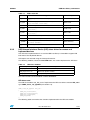
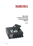
The block diagram in Figure 5 shows the interactions between those modules.
Figure 5.
Block diagram organization of the MSC driver
User MSC application callback
File access (OPEN,READ,WRITE)
User callbacks call
Filesystem (EFSL)
Filesystem interface
Page READ/WRITE
MSC Class
Filesystem init
MSC core state machine
SCSI commands
-READ(10) / WRITE(10)
-TEST_UNIT_READY
-MODE_SENSE(6)
-READ_CAPACITY(10)
-REQUEST_SENSE
BOT state machine
BULK IN / OUT
Control Class requests:
-GET_MAX_LUN
-BOT_RESET
USB I/O requests
Operation flow description:
The MSC core state machine starts with the required device initializations, which are:
■
Issuing GET_MAX_LUN class request for detecting the number of device logical units
present on the device. Please note that only devices with one logical unit are supported.
■
Issuing BOT_RESET class requests for resetting the device BOT state machine.
■
Issuing SCSI commands: MODE_SENSE for detecting if the device is write-protected and
READ_CAPACITY for detecting the size of the flash pendrive.
After the above device initializations, the MSC core state machine calls the application user
callback.
The user callback can do any type of file access into the used filesystem. This operation is
translated into a logical page read or write operation. The filesystem interface provides the
connection between the used filesystem and the MSC driver.
At the SCSI level, the logical page read or write operations are converted into SCSI
commands: READ(10) or WRITE(10). Those commands are transfered to the flash pendrive
device using the “Bulk-Only Tranport” protocol.
The BOT layer state machine issues the required Bulk IN and Bulk OUT transactions using
the core USB I/O request module.
Each MSC module is described below.
14/31
Doc ID 18153 Rev 1
UM1021
USB host library architecture
MSC core module:
The MSC core module “usb_msc_core.c” implements the MSC driver, which is defined in
the structure MSC_cb of type USBH_Class_cb_TypeDef (see section 2.3).
USBH_Class_cb_TypeDef MSC_cb =
{
USBH_MSC_InterfaceInit,
USBH_MSC_InterfaceDeInit,
USBH_MSC_ClassRequest,
USBH_MSC_Handle,
};
Table 7.
MSC core module
Function
Description
USBH_MSC_InterfaceInit
Parses interface and endpoints descriptors and configures
host channels (bulk IN and bulk OUT pipes)
USBH_MSC_InterfaceDeInit
De-initialization routine (freeing host channels)
USBH_MSC_ClassRequest
In case of MSC, this function only moves the library core state
machine to the HOST_CLASS state
USBH_MSC_Handle
Implements the MSC handler core state machine
USBH_MSC_Issue_BOTReset
Issues a BOT reset class request
USBH_MSC_Issue_GETMaxLUN Issues a GET_MAX_LUN class request
USBH_MSC_ErrorHandle
MSC error handling
MSC BOT module:
The MSC “Bulk-Only Transport” (BOT) module implements the transport protocol for
sending the SCSI commands (such as READ (10) or WRITE(10)). This module is
implemented in file “usbh_msc_bot.c”.
For details about the BOT protocol, please refer to the usb.org mass storage class
document.
The BOT module has the following functions:
Table 8.
MSC BOT module
Function
Description
USBH_MSC_Init
Initialize BOT state machine
USBH_MSC_HandleBOTXfer
BOT transfer state machine
MSC SCSI module:
The SCSI “Small Computer System Interface” module “usb_msc_scsi.c” stands on top of
the BOT. It implements the set of SCSI commands required to access the flash pendrives.
Doc ID 18153 Rev 1
15/31
USB host library architecture
UM1021
The implemented commands are:
Table 9.
MSC SCSI commands
Function
Description
USBH_MSC_Read10
Command for logical block read
USBH_MSC_Write10
Command for logical block write
USBH_MSC_TestUnitReady
Command for checking device status
USBH_MSC_ReadCapacity10
Command for requesting the device capacity
USBH_MSC_ModeSense6
Command for checking the Write-protect status of the mass
storage device
USBH_MSC_RequestSense
Command for getting error information
MSC filesystem interface module
The MSC filesystem interface module “usbh_msc_fs_interface.c” allows interfacing of
filesystems with the MSC driver. This module should be ported to the selected filesystem.
The current USB host library package comes with the open source, EFSL FAT filesystem
support (see next section for an overview about the EFSL API).
The implemented functions in the filesystem interface are:
Table 10.
MSC filesystem interface functions
Function
Note:
Description
if_initInterface
Allows initalization of the filesystem (for example, reading
capacity of flash pendrive)
if_readBuf
Interface function for a logical page read
if_writeBuf
Interface function for a logical page write
if_TestUnitReady
Interface function for testing if unit is ready
if_RequestSense
Interface function for requesting error information using SCSI
command Request Sense
For the EFSL filesystem, the page size is fixed to 512 bytes. Flash pendrives with higher
page granularity are not supported.
EFSL filesystem overview
The EFSL “Embedded Filesystem Library” is an open source library for filesystems. It is
intended for embedded devices and supports the Microsoft FAT12, 16 and 32 filesystems.
The following table summarizes the EFSL main API functions. For more details about EFSL,
please refer to http://efsl.be/
16/31
Doc ID 18153 Rev 1
UM1021
USB host library architecture
Table 11.
EFSL main API
Function
2.3.2
Prototype
Description
efs_init
esint8 efs_init(EmbeddedFileSystem *efs, eint8*
opts);
Initializes the filesystem
file_fopen
esint8 file_fopen(File *file, FileSystem *fs,
eint8 *filename, eint8 mode);
Opens a file
file_fclose
esint8 file_fclose(File *file);
Closes a file
file_read
euint32 file_read (File *file, euint32 size,
euint8 *buf);
Reads a file
file_write
euint32 file_write(File *file, euint32 size,
euint8 *buf);
Writes a file
rmfile
esint16 rmfile(FileSystem *fs,euint8* filename);
Removes file
mkdir
esint8 mkdir(FileSystem *fs,eint8* dirname);
Creates directory
ls_openDir
esint8 ls_openDir(DirList *dlist,FileSystem
*fs,eint8* dirname);
Opens directory
ls_getNext
esint8 ls_getNext(DirList *dlist);
Gets next file in directory
USB Human Interface Device (HID) class driver for mouse and
keyboard devices
The HID class implementation in v1.0 of the USB host library is intended to support HID
boot mouse and keyboard devices.
HID reports are received using the interrupt IN transfer.
The following modules, located in class\HID folder, are used to implement the HID class:
Table 12.
HID class modules
file (module)
Description
usbh_hid_core.c /.h
This module implements the HID class core state machine
usbh_hid_mouse.c ./h
HID mouse specific routines
usbh_hid_keyboard.c /.h
HID keyboard specific routines
The main functions of each module are described below.
HID class core:
The HID core module “usb_hid_core.c” implements the HID class driver structure HID_cb of
type USBH_Class_cb_TypeDef (see section 2.3).
USBH_Class_cb_TypeDef HID_cb =
{
USBH_HID_InterfaceInit,
USBH_HID_InterfaceDeInit,
USBH_HID_ClassRequest,
USBH_HID_Handle
};
The following table summarizes the functions implemented in the HID core module.
Doc ID 18153 Rev 1
17/31
USB host library architecture
Table 13.
UM1021
MSC core module functions
Function
Description
USBH_HID_InterfaceInit
Parses interface and endpoint descriptors and configures a
host channel in order to have an interrupt IN pipe (for getting
HID reports)
USBH_HID_InterfaceDeInit
Frees the allocated interrupt IN pipe
USBH_HID_ClassRequest
Implements a state machine of the required class requests for
HID mouse and keyboard devices (ex: getting HID report
descriptors, setting IDLE time, setting Protocol).
USBH_HID_Handle
HID class core state machine (processing of interrupt IN
transfers)
USBH_Get_HID_ReportDescriptor Class request for getting HID report descriptor
USBH_ParseClassDesc
Function used for parsing HID report descriptor
USBH_Set_Idle
Class request for setting IDLE time
USBH_Set_Report
Class request for sending Report OUT data (not used in the
demonstration software)
USBH_Set_Protocol
Class request for setting the HID protocol: Boot or Report(1)
1. USB_Set_Protocol is called to set the Boot protocol mode.
HID mouse & keyboard specific management:
The detection of mouse or keyboard device will be done when parsing interface descriptor in
function USBH_HID_InterfaceInit.
The specific initialization for each type of device and the decoding of the received report IN
data is done by two functions which are declared in a structure of type HID_cb_TypeDef,
which is defined as follows:
typedef struct HID_cb
{
void (*Init)
(void);
void (*Decode) (uint8_t *data);
} HID_cb_TypeDef;
The implementation of the above structures in case a mouse or keyboard is respectively
found in HID_MOUSE_cb and HID_MOUSE_cb is as follows:
HID_cb_TypeDef HID_MOUSE_cb =
{
MOUSE_Init,
MOUSE_Decode,
};
HID_cb_TypeDef HID_KEYBRD_cb=
{
KEYBRD_Init,
KEYBRD_Decode
};
18/31
Doc ID 18153 Rev 1
UM1021
USB host library architecture
Table 14.
Mouse and keyboard intialization & HID report decoding functions
Function
Description
MOUSE_Init
Initialization routine for USB mouse
MOUSE_Decode
HID report decoding for mouse (decoding mouse x, y
positions, pressed buttons)
KEYBRD_Init
Initialization routine for USB keyboard(1)
KEYBRD_Decode
HID report decoding for keyboard (decoding of the key
pressed on the keyboard)
1. Selection of AZERTY or QWERTY keyboard is done through the defines #QWERTY_KEYBOARD ,
#AZERTY_KEYBOARD in file usbh_hid_keybrd.h.
Doc ID 18153 Rev 1
19/31
Library user API and callback functions
UM1021
3
Library user API and callback functions
3.1
Library user API
The library user API functions are limited to the following two functions:
■
void USBH_Process (void): this function implements core state machine process. It
should be called periodically from the user main loop.
■
USBH_Init: this function should be called for the initialization of the USB host hardware
and library.
USBH_Init has the following function prototype:
void USBH_Init(USB_OTG_CORE_HANDLE *pdev,
USBH_Class_cb_TypeDef *class_cb,
USBH_Usr_cb_TypeDef *usr_cb)
– pdev: pointer on the USB host core registers structure (needed for future use)
– class_cb: pointer to a class structure of type USBH_Class_cb_TypeDef. It can be
either MSC_cb for handling MSC devices or HID_cb for handling HID
mouse/keyboard devices.
– usr_cb: pointer to a structure of type USBH_Usr_cb_TypeDef. This structure
defines class-independent callbacks (see section 3.2.2).
3.2
User callback functions
User callbacks are declared in user template file usbh_usr.c.
Two types of user callbacks are defined:
3.2.1
■
Callback functions related to the class operations (MSC or HID)
■
Callbacks functions independent from class operations; they are mainly called during the
enumeration phase. These callbacks are defined in a structure of type
USBH_Usr_cb_TypeDef.
Class callback functions
MSC user callback functions
For MSC, the following callback is used: int USR_MSC_Application (void).
After the end of the class initializations, this function is called by the MSC state machine in
order to give hand to the user for filesystem access operations.
In this callback, the user can implement any access to the FAT filesystem (file open, file
read, file write...) using the EFSL filesystem API.
Also, the user can have access to an exported structure variable from the library MSC class
driver, USBH_MSC_Param. This variable provides some information about the mass
storage key.
20/31
Doc ID 18153 Rev 1
UM1021
Library user API and callback functions
This variable is defined using a structure of type MassStorageParameter_TypeDef defined
as follows:
typedef struct __MassStorageParameter
{
uint32_t MSCapacity; /*MS device capacity in bytes */
uint32_t MSSenseKey; /*Request Sense SCSI command returned value */
uint16_t MSPageLength; /* MS device Page length */
uint8_t MSBulkOutEp; /* Bulk OUT endpoint address */
uint8_t MSBulkInEp; /*Bulk IN endpoint address */
uint8_t MSWriteProtect; /*Write protection status, 0: non protected, 1:protected */
} MassStorageParameter_TypeDef;
HID user callback functions
For the HID class, the following callbacks are defined:
Note:
1
■
void USR_MOUSE_Init(void): user initialization for mouse application
■
void USR_KEYBRD_Init(void): user initializations for keyboard application
■
void USR_MOUSE_ProcessData(HID_MOUSE_Data_TypeDef *data): this callback is
called when an input parameter data of type HID_MOUSE_Data_TypeDef (see Note 1
below) is available.
■
void USR_KEYBRD_ProcessData (uint8_t data): this callback is called when a new
ASCII character is typed. The character is received in input parameter data.
HID_MOUSE_Data_TypeDef is defined as follows:
typedef struct _HID_MOUSE_Data
{
uint8_t x;
uint8_t y;
uint8_t z;
/* Not Supported */
uint8_t button; /*Bitmap showing pressed buttons 1:pressed, 0: non pressed */
}
HID_MOUSE_Data_TypeDef;
Doc ID 18153 Rev 1
21/31
Library user API and callback functions
3.2.2
UM1021
Class-independent callback functions
The class-independent callback functions are defined in a structure of type
USBH_Usr_cb_TypeDef defined as follows:
typedef struct _USBH_USR_PROP
{
void (*Init)(void);
void (*DeviceAttached)(void);
void (*ResetDevice)(void);
void (*DeviceDisconnected)(void);
void (*OverCurrentDetected)(void);
void (*DeviceSpeedDetected)(uint8_t DeviceSpeed);
void (*DeviceDescAvailable)(void *);
void (*DeviceAddressAssigned)(void);
void (*ConfigurationDescAvailable)(USBH_CfgDesc_TypeDef *,
USBH_InterfaceDesc_TypeDef *,
USBH_EpDesc_TypeDef *);
void (*ManufacturerString)(void *);
void (*ProductString)(void *);
void (*SerialNumString)(void *);
void (*EnumerationDone)(void);
USBH_USR_Status (*UserInput)(void);
void (*USBH_USR_DeviceNotSupported)(void);
void (*UnrecoveredError)(void);
}
USBH_Usr_cb_TypeDef;
The above callback functions are described below.
– Init: called during initialization by USBH_Init core function. In this function, the user
can implement any specific intialization related to his application.
– DeviceAttached: called when a USB device is attached. It can be useful to informthe
user of any device attachement using a display screen.
– DeviceReset: called after an USB reset is issued from the host.
– DeviceDisconnect: called when a device is disconnected.
– OverCurrentDetected: called when an overcurrent is detected on USB VBUS.
– DeviceSpeedDetected: called when the device speed is detected1).
– DeviceDescAvailable: called when a device descriptor is available2).
– DeviceAddressAssigned: called when the device address is assigned.
– ConfigurationDescAvailable: called when configuration, interface and endpoints
descriptors are available3).
– ManufacturingString: called when manufacturing string is extracted.
– ProductString: called when product string is extractcted.
– SerialNumString: called when serial num string is extracted.
– EnumerationDone: called when enumeration finished.
– UserInput: called after the end of the enumeration process, for prompting the user for
further action, such as pressing a button to start a host class operation4).
– USBH_USR_DeviceNotSupported: called when the detected device is not
supported by the current class driver.
– UnrecoveredError: called when the core state machine is in
“HOST_ERROR_STATE” state. It allows the user to handle any error, by displaying
an error message on the LCD screen, for example.
22/31
Doc ID 18153 Rev 1
UM1021
Note:
Library user API and callback functions
1
Device speed information is returned in the DeviceSpeed parameter. Possible values are:
0x1 for full-speed devices and 0x2 for low-speed devices.
2
Device descriptor information is returned in the pointer DeviceDesc, which points to a
structure of type USBH_DevDesc_TypeDef defined as follows:
typedef struct _DeviceDescriptor
{
uint8_t
bLength;
uint8_t
bDescriptorType;
uint16_t bcdUSB;
/* USB Specification Number which device complies too */
uint8_t
bDeviceClass;
uint8_t
bDeviceSubClass;
uint8_t
bDeviceProtocol;
uint8_t
bMaxPacketSize;
uint16_t idVendor;
/* Vendor ID (Assigned by USB Org) */
uint16_t idProduct;
/* Product ID (Assigned by Manufacturer) */
uint16_t bcdDevice;
/* Device Release Number */
uint8_t
iManufacturer; /* Index of Manufacturer String Descriptor */
uint8_t
iProduct;
/* Index of Product String Descriptor */
uint8_t
iSerialNumber; /* Index of Serial Number String Descriptor */
uint8_t
bNumConfigurations; /* Number of Possible Configurations */
}
USBH_DevDesc_TypeDef;
Doc ID 18153 Rev 1
23/31
Library user API and callback functions
3
UM1021
Device configuration information (config, interface and endpoint descriptors) are returned
with pointers on structures USBH_CfgDesc_TypeDef, USBH_InterfaceDesc_TypeDef
and USBH_EpDesc_TypeDef defined as follows:
typedef struct _ConfigurationDescriptor
{
uint8_t
bLength;
uint8_t
bDescriptorType;
uint16_t wTotalLength;
uint8_t
bNumInterfaces;
uint8_t
bConfigurationValue;
uint8_t
iConfiguration;
uint8_t
bmAttributes;
uint8_t
bMaxPower;
}
USBH_CfgDesc_TypeDef;
typedef struct _InterfaceDescriptor
{
uint8_t bLength;
uint8_t bDescriptorType;
uint8_t bInterfaceNumber;
uint8_t bAlternateSetting;
/* Value used to select alternative setting */
uint8_t bNumEndpoints;
/* Number of Endpoints used for this interface */
uint8_t bInterfaceClass;
/* Class Code (Assigned by USB Org) */
uint8_t bInterfaceSubClass;
/* Subclass Code (Assigned by USB Org) */
uint8_t bInterfaceProtocol;
/* Protocol Code */
uint8_t iInterface;
/* Index of String Descriptor Describing this
interface */
}
USBH_InterfaceDesc_TypeDef;
typedef struct _EndpointDescriptor
{
uint8_t
bLength;
uint8_t
bDescriptorType;
uint8_t
bEndpointAddress;
/* indicates what endpoint this descriptor is
describing */
uint8_t
bmAttributes;
/* specifies the transfer type. */
uint16_t wMaxPacketSize;
/* Maximum Packet Size this endpoint is capable of
sending or receiving */
uint8_t
bInterval;
/* is used to specify the polling interval of certain
transfers. */
}
USBH_EpDesc_TypeDef;
4
In order to move the core state machine to HOST_CLASS_REQUEST state, UserInput
callback should return the value USBH_USR_RESP_OK of type USBH_USR_Status
typedef enum {
USBH_USR_NO_RESP
= 0, /*no response from user */
USBH_USR_RESP_OK = 1,
}
USBH_USR_Status;
24/31
Doc ID 18153 Rev 1
UM1021
Demo firmware
4
Demo firmware
4.1
Mass storage class demo
4.1.1
Software initializations
The following code extract from main.c file shows the initializations required before calling
the USBH_Process for managing the core state machine.
USB_Init is called with parameters defining the class driver, which is the MSC class driver,
and also the user callbacks.
int main(void)
{
/* Setup STM32 Hardware Configuration */
BSP_Init();
/* Init Host Library */
USBH_Init(&USB_OTG_FS_dev, &MSC_cb , &USR_Callbacks);
while (1)
{
/* Host Task handler */
USBH_Process();
}
}
4.1.2
Mass storage device enumeration
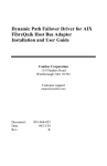
When attaching a full-/low-speed device to the STM3210C_eval board, the LCD displays the
following text (for example, when plugging the Kingston DataTraveler G2 flash pendrive):
Figure 6.
MS device enumeration
STM32F105/7 USB HOST DEMO
> DEVICE ATTACHED
> DEVICE IS FULL SPEED
> DEVICE SUPPORTS MASS STORAGE CLASS
VID = 0951h
PID = 1624h
NumEndpoints = 2
Manufacturer : Kingston
Product : DataTraveler G2
Serial Number : 001CC0EC309BF9C196A50D64
> ENUMERATION COMPLETED
---------------------------------------To see the root content of the disk :
‘ Press Key B3 ...’
Doc ID 18153 Rev 1
25/31
Demo firmware
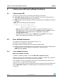
4.1.3
UM1021
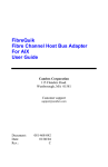
Accessing mass storage device content
After the end of enumeration, pressing button B3 displays the screen below, which provides
the following information:
■
Flash pendrive capacity (in Mbytes)
■
Root folder files
Figure 7.
MS device content access
STM32F105/7 USB HOST DEMO
* Size of the disk in MBytes:
---------------------------------------1910
* Root folder has the following entries:
---------------------------------------FILE1.TXT
FILE2.TXT
IMG1.BMP
IMG2.BMP
FILE3.BIN
To continue ‘Press key B3’
Please note that, after browsing the mass storage device content, a simple text file
“HostDemo.txt” is written into the flash pendrive (assuming that it is not write-protected).
For testing file read access, the user can start an image slideshow on the LCD screen,
assuming that some bmp images are available in the root folder of the flash pendrive.
Note:
4.1.4
1
Some bmp images with LCD screen size are provided in the project folder.
2
If the device is write-protected, a warning message is displayed on the LCD screen.
3
Mass storage devices with multiple logical units are not supported (an error message is
displayed on the LCD screen).
4
If no bmp image is available in the flash pendrive root folder, a warning message is
displayed on the LCD screen and, after 2 seconds, the host re-initializes (restarts
enumeration of the flash pendrive).
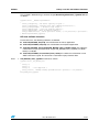
Flash pendrive tests
Because an embedded USB host is considered limited, these interoperability tests:
1.
Enumeration,
2.
Cold Boot with device attached,
3.
Hot detach/attach,
4.
Browsing root content,
5.
Creation of "hostdemo.txt" file,
6.
Data read from device to TFT-LCD: images slide-show,
7.
Messaging to TFT-LCD (no silent failure)
are successfully applied to the following table selection of various flash pendrives using the
STM32F105/7 USB host library and the demonstration provided with the mass storage
example.
26/31
Doc ID 18153 Rev 1
UM1021
Demo firmware
Table 15.
Tested flash pendrives
Manufacturer
Name
Size
VID
PID
Kingston
Data Traveler 2GB
2GB
0x0951
0x1603
Lexar
JumpDrive Sport
265MB
0x05DC
0xA410
Lexar
JumpDrive FireFly
265MB
0x05DC
0xA575
Lexar
JumpDrive2.0 pro
256MB
0x05DC
0x0200
Memorex
TravelDrive Classic 003C
512MB
0x08EC
0x0008
Memorex
TravelDrive Classic 003B
2 GB
0x12F7
0x1A00
Sandisk
USB Flash Drive
8 GB
0x0781
0x5541
Sandisk
USB Flash memory
8 GB
0x0781
0x6545
Sandisk
U3 Cruzer Micro -U3
1 GB
0x0781
0x5406
Sandisk
Cruzer Colors+
4 GB
0x0781
0x5170
Sandisk
Cruzer Pro
1 GB
0x08EC
0x0507
Sandisk
Cruzer Micro
512 MB
0x0781
0x5151
Kingmax
USB2.0FlashDisk
2 GB
0x1687
0x6211
Netac
USB Flash Disk
128 MB
0x0DD8
0XD202
PNY
Attaché 2.0
128 MB
0x08EC
0x0012
PNY
Attaché Pro
1 GB
0x13FF
0x1A23
Sony
Micro Vault Tiny
2 GB
0x054C
0x02A5
Toshiba
USB Flash memory
2 GB
0x0930
0x6545
Transcend
JetFlash V30
1 GB
0x058F
0x6387
Corsair
Flash Voyager Mini
8 GB
0x1B1C
0x0B29
Philips
FM01FD00B
1 GB
0x0471
0X082B
4.2
HID mouse and keyboard demos
4.2.1
Initializations
Same as for mass storage devices (see section 4.1.1), except that the HID class driver is
selected in the USBH_Init function:
/* Init Host Library */
USBH_Init(&USB_OTG_FS_dev, &HID_cb , &USR_Callbacks);
4.2.2
Mouse or keyboard device enumeration
Similar to mass storage devices (see section 4.1.2).
Doc ID 18153 Rev 1
27/31
Demo firmware
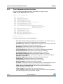
4.2.3
UM1021
Mouse demo
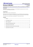
After mouse device enumeration, pressing button B3 displays the following screen, which
shows the mouse 3 buttons and the pointer (green cross).
Figure 8.
Mouse demo
USB HOST HID DEMO
USB HOST MODE
HID DEMO Device: Mouse
x
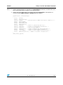
4.2.4
Keyboard demo
After keyboard enumeration, pressing button B3 displays an LCD screen where the user can
type some text:
Figure 9.
Keyboard demo
USB HOST HID DEMO
USB HOST MODE
HID DEMO Device: Keyboard
Hello testing azerty keyboard...
4.3
Demo footprints
The following tables provide footprint data when the software is compiled using IAR EWARM
v5.50.5 with high optimizations for size:
Table 16.
Demo footprints
Demo
Mass Storage class demo
HID mouse & keyboard demo
28/31
Code + RO data
~32 Kb
~24 Kb
Doc ID 18153 Rev 1
RAM
6.4 Kb
5 Kb
UM1021
5
Known limitations
Known limitations
The current version of the STM32F105/7 USB host stack has the following known
limitations:
1.
It supports only two USB standard class applications, i.e:
a)
Mass Storage Class (MSC) for accessing USB flash pendrives,
b)
Human Interface Device (HID) class for keyboard and mouse devices.
2.
It supports only one interface and one configuration selection (default config).
3.
It does not support mass storage devices with multiple logical units.
4.
It comes with the EFSL FAT filesystem support:
a)
The page size is fixed to 512 bytes. Flash pendrives with higher page granularity
are not supported.
b)
Long filenames and Unicode are not supported.
5.
Very short delay between device detach/attach may result in abnormal operation.
6.
Compatibility issues have been encountered with some devices (not listed in Table 15)
at the enumeration phase.
7.
After connecting and disconnecting a non-supported class device and then attaching a
supported class device, enumeration is done properly, but the device cannot be
accessed. A device reset is needed.
Doc ID 18153 Rev 1
29/31
Revision history
6
UM1021
Revision history
Table 17.
30/31
Document revision history
Date
Revision
26-Nov-2010
1
Changes
Initial release.
Doc ID 18153 Rev 1
UM1021
Please Read Carefully:
Information in this document is provided solely in connection with ST products. STMicroelectronics NV and its subsidiaries (“ST”) reserve the
right to make changes, corrections, modifications or improvements, to this document, and the products and services described herein at any
time, without notice.
All ST products are sold pursuant to ST’s terms and conditions of sale.
Purchasers are solely responsible for the choice, selection and use of the ST products and services described herein, and ST assumes no
liability whatsoever relating to the choice, selection or use of the ST products and services described herein.
No license, express or implied, by estoppel or otherwise, to any intellectual property rights is granted under this document. If any part of this
document refers to any third party products or services it shall not be deemed a license grant by ST for the use of such third party products
or services, or any intellectual property contained therein or considered as a warranty covering the use in any manner whatsoever of such
third party products or services or any intellectual property contained therein.
UNLESS OTHERWISE SET FORTH IN ST’S TERMS AND CONDITIONS OF SALE ST DISCLAIMS ANY EXPRESS OR IMPLIED
WARRANTY WITH RESPECT TO THE USE AND/OR SALE OF ST PRODUCTS INCLUDING WITHOUT LIMITATION IMPLIED
WARRANTIES OF MERCHANTABILITY, FITNESS FOR A PARTICULAR PURPOSE (AND THEIR EQUIVALENTS UNDER THE LAWS
OF ANY JURISDICTION), OR INFRINGEMENT OF ANY PATENT, COPYRIGHT OR OTHER INTELLECTUAL PROPERTY RIGHT.
UNLESS EXPRESSLY APPROVED IN WRITING BY AN AUTHORIZED ST REPRESENTATIVE, ST PRODUCTS ARE NOT
RECOMMENDED, AUTHORIZED OR WARRANTED FOR USE IN MILITARY, AIR CRAFT, SPACE, LIFE SAVING, OR LIFE SUSTAINING
APPLICATIONS, NOR IN PRODUCTS OR SYSTEMS WHERE FAILURE OR MALFUNCTION MAY RESULT IN PERSONAL INJURY,
DEATH, OR SEVERE PROPERTY OR ENVIRONMENTAL DAMAGE. ST PRODUCTS WHICH ARE NOT SPECIFIED AS "AUTOMOTIVE
GRADE" MAY ONLY BE USED IN AUTOMOTIVE APPLICATIONS AT USER’S OWN RISK.
Resale of ST products with provisions different from the statements and/or technical features set forth in this document shall immediately void
any warranty granted by ST for the ST product or service described herein and shall not create or extend in any manner whatsoever, any
liability of ST.
ST and the ST logo are trademarks or registered trademarks of ST in various countries.
Information in this document supersedes and replaces all information previously supplied.
The ST logo is a registered trademark of STMicroelectronics. All other names are the property of their respective owners.
© 2010 STMicroelectronics - All rights reserved
STMicroelectronics group of companies
Australia - Belgium - Brazil - Canada - China - Czech Republic - Finland - France - Germany - Hong Kong - India - Israel - Italy - Japan Malaysia - Malta - Morocco - Philippines - Singapore - Spain - Sweden - Switzerland - United Kingdom - United States of America
www.st.com
Doc ID 18153 Rev 1
31/31