1
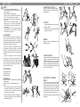
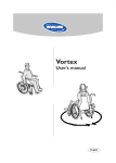
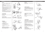
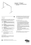
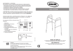
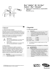
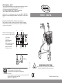
MAINTENANCE – SAFETY
To ensure good performance and safety you should regularly check that the following is carried out:
• Clean the rollator with ordinary cleaning agent. Wipe it dry. Keep the wheels clean.
• Check that screws and adjustments are properly tightened.
• If your rollator is not functioning perfectly - contact your dealer immediately.
Never use a defective rollator. Do not attempt repairs yourself!
P429/2 - DELTA
NB. Only to be used as a walking support. User’s max. weight: P429/2 - DELTA135 kg.
Dolomite will not accept responsibility for adaptations, faulty repairs etc. that are outside its
control.
Instructions for destruction of product and packaging:
When the product can no longer be used, it and its accessories as well as the packaging
material should be sorted correctly. The individual parts can be separated and dealt with
according to the list specification.
2
6
7
All important technical information is to be
found on the label of the P429/2 - DELTA.
1:
3:
4:
5:
6:
7:
8:
9:
1
Article number
Lot number
Date of manufacture
Max. user weight
NB. See operating instructions.
In- and outdoor rollator.
Max. width of rollator.
Manufacturer’s name
XXXXX - XX - XX
XXXXXX - XXXXXX
4
3
5 8
9
81-94 cm
67 cm
Manufacture:
Invacare REA, Växjövägen 303, SE-343 75 Diö, SWEDEN
TEL +46 (0)476 535 00, FAX +46 (0)476 535 98, www.dolomite.biz
Sales companies:
Invacare UK Operations Ltd, Pencoed Technology Park, Pencoed, UK-Bridgend CF35 5HZ
TEL (44) (0)1656 776 200, FAX (44) (0)1656 776 201
[email protected], [email protected]
1513153-4 100326
OPERATING INSTRUCTIONS
Read carefully through the operating instructions before use.
The rollator is adapted for both indoor and outdoor use.
ENOPERATING INSTRUCTIONS
P429/2 - DELTA
SAFETY
EN
OPERATING POSITION
Open the rollator into operating position.
NB. Always check that the safety catch is in
locked position
-The rollator must be fully unfolded when used as a walking support. NB. Only to be used as a
walking support.
- Exercise caution on sloping ground.
- Do not go up or down stairs with the rollator.
- Do not use the rollator on an escalator.
- Exercise caution when there is a heavy load in the basket.
-Loads should be transported solely in the
basket, bag or on the tray. Max. overall load in
the basket and on the tray is 5 kg. Max. load in
the bag 5 kg.
- The handlebars must not be angled outside the
marked position as this reduces the rollator’s
lateral stability, see figure A.
A
FOLDING
1.Pull the safety catch upwards - backwards.
2.Fold the rollator.
NB. Be aware of the risk of crushing between
the parts of the frame.
HANDLEBARS
NB. The handlebars must point directly backwards
when using the rollator. Under no circumstances
should they be angled outwards. The vertical line
in the knurling must be located in the middle of the
indentation in the frame, see picture A.
To adjust the height of the handles: Undo the
locking levers and adjust the handles to a suitable
height. NB. The handles must never be set above
their highest position, indicated by the knurling on
the tubes.
- Tighten the locking levers, which should then
be adjusted so that they point downwards. (The
locking levers can be freely turned by first pulling
them outwards). Check that the handles are set at
the same height. The handles should normally be
positioned at wrist height.
P429/2 - DELTA
1
2
BRAKES
Apply the brakes by pulling both brake
handles upwards.
PARKING BRAKE
B
C
Press the brake handles carefully downwards
to apply the parking brakes. A distinct click
indicates that the brake is in the correct
position. It is important that both the brakes
are put into parking position when they are
to be used. To release the parking brake, pull
the brake handle upwards.
ACCESSORIES
B) Fitting the basket.
C) Fitting the tray.
D) Fitting the bag.
ASSEMBLING
Before the rollator is assembled remove plastic caps
in the side tubes.
Open the rollator into operating position (see
below).
1. Fit the locking lever with the bolt. The locking
lever with the washer shall be installed on the
outside. Ensure that the head of the bolt slots
into the recess on the fitting.
2.Insert the handle tubes into the side uprights and
tighten the locking levers. These must be pointing
downwards during use.
2
ADUSTMENT OF BRAKE
EFFECT
D
1
Two setting screws, one in the brake lever
and one in the middle of the brake cable
adjust the tension of the brake and the application of the brake to the user’s capability.
The braking power increases and the movement required in the brake lever is reduced
when the setting screws are loosened.
2
NB. Make sure to tighten the lock nuts after
adjustment.
8 + 10 mm
3