1
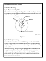
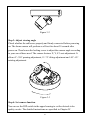
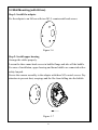
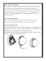
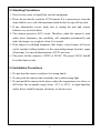
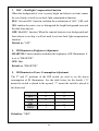
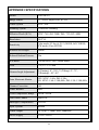
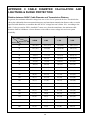
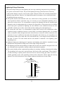
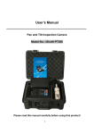
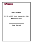
V5822IR-A3 SERIES
VANDAL RESISTANT IR FIXED
MINIDOME CAMERA
User Manual
CONTENTS
CHAPTER I DESCRIPTION .......................................................................... 1
CHAPTER II MAIN FEATURES ................................................................... 2
CHAPTER III INSTALLATION..................................................................... 3
3.1 SURFACE MOUNTING ......................................................................... 3
3.2 WALL MOUNTING (WITH 86 BOX).................................................... 6
3.3 HANDLING PRECAUTIONS................................................................ 8
3.4 INSTALLATION PRECAUTIONS......................................................... 8
CHAPTER IV CAMERA FUNCTION SETTING ........................................ 9
APPENDIX I SPECIFICATIONS ................................................................. 12
APPENDIX II CABLE DIAMETER CALCULATION AND
LIGHTNING & SURGE PROTECTION..................................................... 14
CHAPTER I DESCRIPTION
Thank you very much for purchasing our product.
Infinova’s V5822IR-A3 series high resolution IR minidome cameras feature a
high sensitivity 1/3" SONY Super HAD II CCD sensor. Advanced Digital
Signal Processing (DSP) provides 520 TV lines of resolution and authentic
images. The built-in IR illuminators with 25 meters of radiant distance provide
super imaging performance at nighttime. These cameras are the perfection
solution for a 24x7 around-the-clock surveillance.
V5822IR-A3 series IR minidome cameras employ vandal resistant minidome
housing, making them the ideal choice for the hazardous surveillance
environments. The cameras provide easy installation, designed for surface
mount with 3-axis adjustment.
This manual is for the following models:
V5822IR-A3014SE
IR minidome camera, 1/3 inch CCD,
Vandal-resistant, 3-axis, Day/night,
520TVL, PAL, 12VDC/24VAC,
Surface mount, 3.3-12mm vari-focal lens
V5822IR-A3004SE
IR minidome camera, 1/3 inch CCD,
Vandal-resistant, 3-axis, Day/night,
520TVL, NTSC, 12VDC/24VAC,
Surface mount, 3.3-12mm vari-focal lens
1
CHAPTER II MAIN FEATURES
y 1/3" SONY high resolution Super HAD II CCD sensor
y Resolution: 520 TVL
y IR-Cut Removable (ICR) Filter for Day/Night switching
y Built-in IR illuminators, 850nm wavelength, 25 meters radiant distance
y Adjustable power consumption of IR illuminators
y Super imaging performance at nighttime
y Auto Electronic Shutter (AES), Auto Gain Control (AGC), Backlight
Compensation (BLC)
y Aspherical, auto-iris, vari-focal lens with IR correction
y LEVEL adjustment
y Surface Mount, 3-axis adjustment
2
CHAPTER III INSTALLATION
3.1 Surface Mounting
Step 1: Prepare mounting holes
If the minidome camera’s pigtail is dragged out from the top of upper housing,
drill mounting holes at the desired position. See the figure below for the size
and location of mounting holes.
Ø30.0
Cable hole
Ø5
.5
5
13
°
13
5°
30.0
Ø92.0
Mounting hole
(Unit: mm)
Figure 3-1
Step 2: Install upper housing
Loosen the three mum-head screws in bubble flange and take off the bubble.
For ease of installation, upper housing and dome bubble are connected with a
safety lanyard. Pay attention to prevent dust, scrapings and the like from falling
into the bubble.
There are DIP switch, Blemish correction button and three mounting holes in
the upper housing. Refer to Chapter IV for detailed operation instruction.
Install the upper housing to the desired position with three M4*25 conical
tapping screws and then connect the properly arranged cables with external
power source and relevant devices.
3
Figure 3-2
Step 3: Adjust viewing angle
Check whether the cables are properly and firmly connected before powering
on. The dome camera will perform a self-test for about 30 seconds after
power-on. Then loosen the locking screw to adjust the camera angle according
to your surveillance need. The camera features X, Y, Z 3-axis adjustment. It
allows 0°~350° panning adjustment, 0°~75° tilting adjustment and -85°~85°
rotating adjustment.
Figure 3-3
Step 4: Set camera function
You can use the DIP switch in the upper housing to set the desired video
quality on site. The detailed instructions are specified in Chapter IV.
4
Step 5: Install dome bubble
Install the bubble flange to upper housing. In this process, the shielding cover
may block the camera. Thus, before securing the bubble, user should adjust the
shielding cover to a proper position. Then, fasten the screws.
With all the procedures finished, user should further confirm whether each part
of the device is properly and firmly connected.
Figure 3-4
Dimensions (Unit: mm)
Figure 3-5
5
3.2 Wall Mounting (with 86 box)
Step 1: Install the adapter
Fix the adapter to an 86 box with two M3.5 countersunk head screws.
Figure 3-6
Step 2: Install upper housing
Arrange the cables properly.
Loosen the three mum-head screws in bubble flange and take off the bubble.
For ease of installation, upper housing and dome bubble are connected with a
safety lanyard.
Secure the camera assembly to the adapter with three M3 conical screws. Pay
attention to prevent dust, scrapings and the like from falling into the bubble.
Figure 3-7
6
Step 3: Adjust viewing angle
Check whether the cables are properly and firmly connected before powering
on. The dome camera will perform a self-test for about 30 seconds after
power-on. Then loosen the locking screw to adjust the camera angle according
to your surveillance need. The camera features X, Y, Z 3-axis adjustment. It
allows 0°~350° panning adjustment, 0°~75° tilting adjustment and -85°~85°
rotating adjustment.
Step 4: Set camera function
You can use the DIP switch in the upper housing to set the desired video
quality on site. The detailed instructions are specified in Chapter IV.
Step 5: Install dome bubble
Install the bubble flange to upper housing. In this process, the shielding cover
may block the camera. Thus, before securing the bubble, user should adjust the
shielding cover to a proper position. Then, fasten the screws.
With all the procedures finished, user should further confirm whether each part
of the device is properly and firmly connected.
Figure 3-8
7
3.3 Handling Precautions
1. Never let any water or liquid flow into this equipment.
2. Please do not directly touch the CCD element. If it is necessary to clean the
dome bubble, use a soft cloth moistened with alcohol to wipe off any dust.
3. If any abnormality occurs, make sure to unplug the unit and contact
Infinova or your local dealer.
4. This camera possesses AGC circuit. Therefore, when the camera is used
under lower luminance, the sensibility will strengthen automatically and
make the image very rough in vision. It is normal.
5. If the subject is with high luminance (like lamp), vertical stripes will occur
on the monitor (tailing shadow) or the surrounding image becomes vague
(flowering). It is special phenomenon of CCD, not error.
6. The power for this camera is 12VDC or 24VAC. The power 24VAC should
be isolated power only.
3.4 Installation Precautions
1. Do not drop the camera or subject it to strong knock.
2. Do not point the camera lens toward the sun or other strong light.
3. Do not install the camera in the places where the temperatures rise above or
fall below the acceptable range (from -10°C to 50°C), or high humidity
and/or direct rainfall, frequent vibrations, or shocks occur.
8
CHAPTER IV CAMERA FUNCTION SETTING
In the upper housing, a 6-position DIP switch is used to adjust AGC, AES,
BLC, etc. And another button is used to compensate the blemish. See the figure
below for the location of the DIP switch and Blemish correction button.
DIP switch
1
4
OFF
RT
2
3
4
5
6
IR
F
1
S
AE
GH
5
6
5
H
L
6
OF
F
5
LO
W
IR
W
LE
6
MI
D
6
VE
L
5
LO
SMA
BLC
OF
HI
HI
GH
C
AG
LEV
EL
OFF
3
2
C
AG
Blemish correction
button
Operation Instruction:
1. AGC -- [AGC-HIGH/AGC-LOW Selection]
Magnify the signal collected from CCD to an available standard to video
amplifier, and how much it magnifies equals to gain, which means the
sensitivity. Adjust AGC properly to have camera work under a larger
illumination area.
AGC-HIGH: Activate AGC-HIGH function.
AGC-LOW: Activate AGC-LOW function.
Default as: “AGC HIGH”.
2.
AES -- Auto Electronic Shutter Selection
AES: Activate AES function, and camera automatically modulate the
exposure time.
OFF: Shut AES function, and the exposure time is constant.
Default as: “OFF”.
9
3. BLC -- Backlight Compensation Function
When the background of view is pretty bright and objects on front cannot
be seen clearly, it needs to use back light compensation function.
BLC: Activate BLC function, and then the workstations of AGC, AES, and
IRIS confirm the entire view to distinguish the bright background area and
the dark front objects.
OFF: Shut BLC function. When the contrast between view background and
front objects is not big, it will not need to activate back light compensation
function.
Default as: “OFF”.
4.
IR Illuminators Brightness Adjustment
SMART IR: Camera smartly modulates the brightness of IR illuminators if
it set to “SMART IR”.
OFF: Shut.
Default as: “SMART IR”.
5.
IR Illuminators Power Consumption Adjustment
The 5th and 6th positions of the DIP switch are used to set the power
consumption of IR illuminators. See the table below for the details. (“0”
means the switch is placed to the up-end; “1” means the switch is placed to
the down-end.
OFF
LOW
MID
HIGH
5
0
0
1
1
6
0
1
0
1
Default as: “MID”.
10
Blemish correction instruction:
Pressing Blemish correction button, it can compensate the blemish in CCD,
which is caused by long-time work.
Note: In order to offer Black Burst to camera, it needs to cover the lens while
compensating the blemish.
11
APPENDIX I SPECIFICATIONS
Model
V5822IR-A3
Image Sensor
1/3" SONY Super HAD II CCD
Video System
NTSC; PAL
Scanning System
2:1interlace scanning
Effective Pixels (H×V)
NTSC: 768×494, 380K; PAL: 752×582, 440K
Resolution
520 TVL
Sensitivity
Color mode: 0.2 lux @ F1.2 (30 IRE, AGC HIGH);
B/W mode: 0 lux (IR ON)
Infrared Wavelength
850nm
Infrared Radiant Distance
25m
S/N Ratio
> 48 dB (AGC OFF), Black Burst
Lens
F1.4, f=3.3~12 mm
Camera Angle Adjustment
X (Panning): 0°~350°; Y (Tilting): 0°~75°;
Z (Rotating): -85°~85°
Auto Electronic Shutter
OFF: NTSC: 1/60s, PAL:1/50s;
ON: NTSC: 1/60~1/100,000s, PAL:1/50~1/100,000s
Gamma Correction
0.45
White Balance
Auto
Color Temperature Range
2400K~9600K
Auto Gain Control
High/Low
Backlight Compensation
ON/OFF
Sync. System
Internal
Video Output
1.0 Vp-p (75 Ohm), BNC connector
Power Supply
12VDC/24VAC
12
Power Consumption
12VDC: 4.5W; 24VAC: 5W
Operating Temperature
14° F ~ 122° F (-10° C ~ 50° C)
Storage Temperature
-4° F ~ 140° F (-20° C ~ 60° C)
Operating Humidity
0~90% RH (non-condensing)
Unit Dimensions (H×Ø)
3.7"×5.2" (93mm×132mm)
Box Dimensions
(L×W×H)
6.9"×6.9"×6.3" (175mm×175mm×160mm)
Unit Weight
1.9 lbs. (0.85 kg)
Shipping Weight
2.3 lbs. (1.05 kg)
Specifications and appearance are subject to change without notice.
13
APPENDIX II CABLE DIAMETER CALCULATION AND
LIGHTNING & SURGE PROTECTION
Relation between 24VAC Cable Diameter and Transmission Distance
In general, the maximum allowable voltage loss rate is 10% for AC-powered devices. The table below
shows the relationship between transmission power and maximum transmission distance under a certain
specified cable diameter, on condition that the 24VAC voltage loss rate is below 10%. According to the
table, if a device rated at 50W is installed 17-meter away from the transformer, the minimum cable
diameter shall be 0.8000mm. A lower diameter value tends to cause voltage loss and even system
instability.
Diameter (mm)
Distance (ft / m)
Power (W)
0.8000
1.000
1.250
2.000
10
283 (86)
451 (137)
716 (218)
1811 (551)
20
141 (42)
225 (68)
358 (109)
905 (275)
30
94 (28)
150 (45)
238 (72)
603 (183)
40
70 (21)
112 (34)
179 (54)
452 (137)
50
56 (17)
90 (27)
143 (43)
362 (110)
60
47 (14)
75 (22)
119 (36)
301 (91)
70
40 (12)
64 (19)
102 (31)
258 (78)
80
35 (10)
56 (17)
89 (27)
226 (68)
90
31 (9)
50 (15)
79 (24)
201 (61)
100
28 (8)
45 (13)
71 (21)
181 (55)
110
25 (7)
41 (12)
65 (19)
164 (49)
120
23 (7)
37 (11)
59 (17)
150 (45)
130
21 (6)
34 (10)
55 (16)
139 (42)
140
20 (6)
32 (9)
51 (15)
129 (39)
150
18 (5)
30 (9)
47 (14)
120 (36)
160
17 (5)
28 (8)
44 (13)
113 (34)
170
16 (4)
26 (7)
42 (12)
106 (32)
180
15 (4)
25 (7)
39 (11)
100 (30)
190
14 (4)
23 (7)
37 (11)
95 (28)
200
14 (4)
22 (6)
35 (10)
90 (27)
14
Lightning & Surge Protection
The product adopts multi-level anti-lightning and anti-surge technology integrated with gas discharge
tube, power resistor and TVS tube. The powerful lightning and surge protection barrier effectively
avoids product damage caused by various pulse signals with power below 4kV, including instantaneous
lightning, surge and static. However, for complicated outdoor environment, refer to instruction below
for lightning and surge protection:
z The product features with dedicated earth wire, which must be firmly grounded. As for surveillance
sites beyond the effective protection scope, it’s necessary to erect independent lightening rods to
protect the security devices. It’s recommended to separate the lightning rod from the mounting pole,
placing the rod on an independent pole, as shown in the figure below. If the product has to be installed
on the same pole or pedestal for lightning rod, there should be strict insulation between the video
cable BNC terminal, power cable, control cable and the standing pole of the lightning rod.
z For suburb and rural areas, it’s recommended to adopt direct burial for the transmission cables.
Overhead wiring is prohibited, because it’s more likely to encounter lightning strike. Use shielded
cables or thread the cables through metal tubes for burial, thus to ensure the electric connection to the
metal tube. In case it’s difficult to thread the cable through the tube all the way, it’s acceptable to use
tube-threaded cables only at both ends of the transmission line, yet the length in burial should be no
less than 15 meters. The cable sheath and the tube should be connected to the lightning -proof
grounding device.
z Additional high-power lightning-proof equipment and lightning rods should be installed for strong
thunderstorm or high induced voltage areas (such as high-voltage substation).
z The lightning protection and grounding for outdoor devices and wires should be designed in line with
the actual protection requirement, national standards and industrial standards.
z The system should perform equipotential grounding by streaming, shielding, clamping and earthing.
The grounding device must meet anti-interference and electric safety requirements. There should be
no short-circuiting or hybrid junction between the device and the strong grid. Make sure there’s a
reliable grounding system, with grounding resistance below 4Ω (below 10Ω for high soil resistivity
regions). The cross-sectional area of the earthing conductor should be no less than 25mm².
LPZOA
30°
LPZOB
30°
Lightning rod
Front device
for surveillance
system
Mounting
pole for
front device
Separated layout for the lightning
rod and the standing pole
15
Infinova
51 Stouts Lane,
Monmouth Junction, NJ 08852, U.S.A.
Tel: 1-888-685-2002 (USA only)
1-732-355-9100
Fax: 1-732-355-9101
[email protected]
V1.2 1205