1
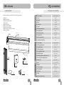
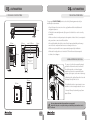
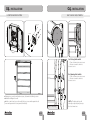
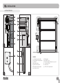
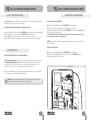
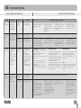
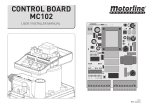
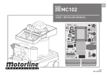
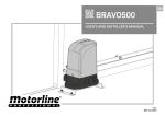
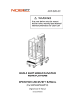
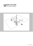
ECO FAST DOOR
USER’S AND INSTALLER’S MANUAL
v1.0
REV. 05/2014
00. CONTENT
01. SAFETY INSTRUCTIONS
▷ INDEX
STANDARDS TO FOLLOW ◁
00. CONTENT
▷ index | pag 01.A
ATTENTION:
▷ To ensure the safety of people, it is important that you read all the following
instructions.Incorrect installation or incorrect use of the product can cause physical
injury and material damage.
▷ Keep these instructions in a safe place for future reference.
▷ This product was designed and produced strictly for the use indicated in this
manual. Any other use, not expressly indicated here, could compromise the good
condition/operation of the product and/or be a source of danger.
▷ ELECTROCELOS SA is not responsible for the improper use of the product,
or other use than that for which it was designed.
▷ ELECTROCELOS SA is not responsible if safety standards were not taken
into account when installing the equipment, or for any deformation that may occur to
it.
▷ ELECTROCELOS SA is not responsible for the safety and proper operation
when using components not sold by them.
▷ Do not make any modifications to the operator components and / or their
accessories.
▷ Beffore installation unplug the automatism from the source of power.
▷ The installer must inform the client how to handle the product in case of
emergency and provide this manual to user.
▷ Keep remote controls away from children, to prevent the automated
system from being activated involuntarily.
▷ The customer shall not, under any circumstances, attempt to repair or tune
the operator .Must call qualified technician only.
▷ Connect the automatism to a 230V plug with ground wire.
▷ Automatism for indoor use only.
01. SAFETY INSTRUTIONS
▷ standards to follow | pag 01.B
02. THE PACKAGE
▷ inside the package | pag 02.A
03. THE AUTOMATISM
▷ technical specifications | pag 02.B
04. INSTALLATION
▷ pre-installation info | pag 03.B
▷ manual opening/closing | pag 03.B
▷ safe profile fixation | pag 04.A
▷ lateral guides fixation | pag 05.A
▷ control board fixation | pag 06.A
▷ limit-switches adjustment | pag 06.B
▷ installation map | pag 07.A
05. MC15 CONTROL BOARD CONFIG
▷ limit-switches verification | pag 08.A
▷ door’s course programming | pag 08.B
▷ pause time configuration | pag 09.A
▷ potentiometers | pag 09.A
▷ transmitters configuration | pag 09.B
06. TROUBLESHOOTING
▷ instructions for final consumers | pag 10.A
▷ instructions for installers | pag 10.A
07. CONTROL BOARD CONNECTIONS
▷ central MC15 motorline | pag 11.A
01.A
01.B
02. PACKAGE
03. AUTOMATISM
▷ INSIDE PACKAGE
TECHNICAL SPECIFICATIONS ◁
▷ Power supply
▷ 01 Motor
▷ 02 Lateral Guides
▷ 01 Safe aluminum profile
▷ 01 Tarpaulin
▷ 01 Control board
▷ 01 Photocells Set MF101
▷ 01 Exterior Push Button
▷ 01 Metal Plates for Guides FIxation
▷ 01 User’s Manual
▷ Power
250W
▷ Current
1,92A
MOTOR
Inside the package you will find the following components:
Tarpaulin
Lateral
Guides
Metal Plates for
Guides Fixation
<60dB
▷ Torque
18,1Nm
▷ Working temperature
▷ Protection level
TARPAULIN
Fixation
Screws
IP55
Intensive
Class F
16µ
▷ Starting up capacitator
20µ
▷ Power supply
230V 50/60Hz
▷ Working temperature
-40°C to 65°C
▷ Protection level
▷ Working frequency
IP55
Intensive
▷ Courtesy light output
230V 100W
▷ RGB LEDs output
24V 100mA
▷ Maximum power output for motor
▷ Acessory power supply output
▷ Dimensions
▷ Weight
▷ Tensile strength
▷ Tear strength
▷ Adhesion
▷ Finish
▷ Working temperatures
02.A
-30°C to 70°C
▷ Working capacitator
▷ Wire
Control
Board
User ‘s
Manual
132RPM
▷ Noise level
▷ Isolation class
CONTROL BOARD MC15
Motor
▷ RPM
▷ Working frequency
Safe Aluminum
Profile
230V 50/60Hz
750W
24V 6W
108x138mm
1100 dtex PES HT
670g/m²
2800N/5cm
300N
90N/5cm
Varnished both sides
-30°C to 70°C
02.B
03. AUTOMATISM
04. AUTOMATISM
▷ TECHNICAL SPECIFICATIONS
PRE-INSTALLATION INFO ◁
For a proper ECO FAST DOOR function, check the following parameters before
installing the automatismo:
▷ Read all steps at least once in order to get familiar with the installation and
configuration process.
165mm
▷ Check the horizontal alignment of the ground so that the door can be correctly
assembled.
27mm
250mm
160mm
máx: 3200mm
▷ Make sure there is an adequate protection against electrical shorts / current peaks
and ground wire connection in Electrical Box.
35mm
▷ Be careful handling directly the control board. Improper handling can damage
some electrical components and even cause damage to the user.
▷ Make sure you have all the necessary materials prepared for installation.
215mm
410mm
Width
Door’s free
space
max:3000mm
40mm
MANUAL OPENING/CLOSING ◁
To open or close the door manually, simply
pull and hold down the unlock lever in the
shaded image and use a 6mm hexagon
wrench to rotate the screw installed in the
bottom of the engine, as shown on the image.
100mm
▷ Rotating to the right will open the door and
Rotating to the left will close it.
148mm
205mm
▷ Evaluate the safety devices to be installed. This will ensure that unexpected
accidents do not happen.
115mm
To facilitate the task use an automatic screw
machine, in order to rapidly rotate the screw.
252mm
- For every 10 turns, the door will go up / down
about 250mm.
It is very important that all precautions are respected!
Only in this way the correct functioning and durability of automatism can be
achieved!
133mm
03.A
03.B
04. INSTALLATION
04. INSTALLATION
▷ SAFE PROFILE FIXATION
SAFE PROFILE FIXATION ◁
(FREE DOOR SPACE)
85mm
A
B
D
C
E
1▷ Apply the safe aluminum profile in the wall’s installation location as shown in (A),
taking into account the horizontal position and the measures indicated in (B).
The safe should also be centered with the door’s free space.
2▷ Make holes at the marked locations, and then apply the safe profile on the wall and
secure with expansion bolts and screws - scheme (D).
The safe must be firmly fixed so that accidents do not occur.
Based on existing holes in the support plates, mark the locations for drilling - scheme
(C).
In the scheme (E) is visible the safe already properly tightened.
04.A
04.B
04. INSTALLATION
04. INSTALLATION
▷ LATERAL GUIDES FIXATION
LATERAL GUIDES FIXATION ◁
4▷ Attach the lateral guides on the
support plates with screw, tightening
them in the nuts located on the guides.
I
F
G
3▷ Unlock the motor pulling the lever down
(see page 06.A 05 ) and manually pull the
tarpaulin down for about 500mm as visible in
(F).
J
5▷ Fix the lateral guides to the ground
using the existing plates. Start by
making the holes in the ground using
the existing holes on plates for the
application of screws. Finally, fasten
the screws until the guide is properly
secure.
Now apply the lateral guides, by placing them
at the inner side of the support plates and
against the wall (G).
The tarpaulin should be inside the guides (H),
so that it can move up and down always
within guides.
H
05.A
05.B
04. INSTALLATION
04. INSTALLATION
▷ CONTROL BOARD FIXATION
LIMIT-SWICHES ADJUSTMENT ◁
195mm
EXPANSION
BOLTS
SCREWS
Y
174mm
A ▷ Closing limit-switch
▷ Turn clockwise to increase course
▷ Rotate counterclockwise to
decrease course
A
B ▷ Opening limit-switch
▷ Turn clockwise to increase course
▷ Rotate counterclockwise to
decrease course
B
1▷Taking into account the indicated measures, determine the drilling location.
2▷ Make the drilling in the wall.
3▷ Fix the control board case on the wall. Must use screws with expansion bolts
(screws and expansion bolts not provided in this kit).
Region’s detail (Y)
06.A
NOTE ▷ The limit-switches will
already be adjusted from factory to
the door dimensions.
06.B
04. INSTALLATION
▷ INSTALLATION MAP
01
02
01
06
03
07
05
02
B
A
C
08
04
1
04
11
2
D
13
09
12
LEGEND:
01 ▷ Aluminum safe profile
02 ▷ Safe profile’s support plate
03 ▷ Motor
04 ▷ Lateral guides
05 ▷ Motor unlock lever
06 ▷ Limit-switches support
07 ▷ Limit-switches
04
3
10
08 ▷ Tarpaulin
09 ▷ Control board
10 ▷ Guides fixing metal plates to ground
11 ▷ Conection Plug
12 ▷ Photocells
13 ▷ Photocells support plate
4
07.A
05.MC15 CONTROL BOARD CONFIG
05. MC15 CONTROL BOARD CONFIG
▷ LIMIT-SWITCHES VERIFICATION
DOOR’S COURSE PROGRAMMING ◁
The first step in programming the control board is to check all the connections from the
multiple devices to the control board. Check the wiring (pag.11 A).
The LEDs BL e DS must be both ON so that the door can work properly.
If they are not, check the connections of the security devices. In case you
don’t use any security device, please close all circuits with shunts.
You must start the configuration with both potentiometers at middle
adjustment. The final adjustment will be made after programming the door’s
course.
Open:
- The LED FAP must turn off and the LED
FCH must remain on.
▶ Programming the door’s course:
1▷ Unlock the motor pulling the lever down (pag. 07.A 05 ).
2▷ Push the tarpaulin manually untill middle course and release the lever to lock the
motor.
3▷ Press the SEL key and the LED CODE will start to blink. Press again the SEL key as
many times as you need until the LED PGM AUTO starts blinking.
4▷ Press and hold SET key and the door must start to close!
Middle Course:
- The LEDs FAP and FCH must remain
on.
Closed:
- The LED FCH must turn off the LED FAP
must remain on.
After checking the connections, make sure the limit switches are working properly.
▶ Check the Limit-Switches:
1▷Unlock the motor pulling the unlock lever (pag 07.A 05 ) and manually pull the door
to the middle course (pag 03.B).
2▷ Check if the LEDs FCH and FAP are on. If not, check if the connections are properly
made.
3▷ Manually close the door and FCH LED must turn off.
4▷ Manually open the door and FAP LED must turn on.
If LEDs do not go off as explained, it means that the limit switches cables are not
well connected. Switch the wires from terminals 7 and 9 of CN3 connector.
WARNING: If the door starts opening, release the SET key, switch the cables
of the terminals 5 and 7 of CN2 connector and restart this programming.
5▷ Let the door close, open and close once again automatically, always keeping the
SET key pressed.
6▷ Once the door finishes closing for the second time, the LED PGM AUTO will stay ON
permanently and the LED T.MOTOR will start to blink. Release SET key and wait
10seconds until the LED T.MOTOR stops from blinking.
7▷ The programming is now complete and you can use the door normally.
PGM AUTO
SET
SEL
The whole process of programming the limit-switches must be
performed with the control board connected to a 230V power source.
08.A
08.B
05. MC15 CONTROL BOARD CONFIG
05. MC15 CONTROL BOARD CONFIG
▷ PAUSE TIME CONFIGURATION
TRANSMITTERS CONFIGURATION ◁
The pause time is the time that the door stays paused since it completes the opening
maneuver until it starts to close automatically.
▶ Programming the pause time in automatic mode:
1▷ Press the SEL key one time and the LED CODE will start blinking. Press again the SEL
key as many times as you need until the LED T.PAUSA starts blinking.
2▷ Press SET one time and wait as much time as you want for pause time.
3▷ Press SET one time after waiting the desired time and the pause time is defined.
▶ Programming transmitters:
1▷ Press one time the SEL key and the LED CODE will start blinking.
2▷ Press one time the transmitter key you want to operate the door.
3▷ When pressing the transmitter key, the LED CODE must turn and stay ON signaling
the success of the configuration.
If the LED CODE doesn’t stay ON, the transmitter was not programmed. Please
repeat the same steps to try once again.
NOTE: To program several transmitters, repeat the same steps above for each one of
the transmitters.
▶ Erase transmitters:
▷ POTENTIOMETERS
1▷ Press one time the SEL key and the LED CODE will start blinking.
2▷ Press and hold the SEL key for about 5 seconds until the CODE LED turns off,
indicating the memory’s reset success.
▶ Adjust sensibility and force potentiometers:
The force potentiometer controls the force of the motor when opening and closing.
The sensibility potentiometer controls the sensibility of the control board when
detecting obstacles. The more sensitive it is the quicker it will detect any obstacle
during it’s course and invert the orientation of working of the motor.
1▷ To adjust potentiometers, run them with a small screwdriver. Turning to the right
side, will increase and turn to the left will decrease.
NOTE: Everytime you make an adjustment to the force potentiometer, you must
perform a new door’s course configuration (see page 08.B).
T.PAUSA
CODE
SET
SEL
Sensibility
Force
09.A
09.B
06. TROUBLESHOOTING
▷ INSTRUCTIONS FOR FINAL USERS
Anomaly
Procedure
Behavior
INSTRUCTIONS FOR INSTALLERS ◁
Procedure II
Discovering the origin of the problem
▷ Door
doesn't work
▷ Make sure you
have 230V power
supply connected to
operator and if it is
working properly.
▷ Still not
working
▷ Consult a qualified
MOTORLINE technician.
1 ▷ Open control box and check if
it has 230V power supply;
2 ▷ Check input fuses;
▷ Door
doesn’t move
but makes
noise
▷ Unlock door and
move the tarpaulin by
hand to check for
mechanical problems
on the movement
▷ Encountered
problems?
▷ Consult a qualified
MOTORLINE technician.
1 ▷ Check all motion axis and associated motion systems related with the door to find out what is the problem.
▷ The tarpaulin
moves easily?
▷ Consult a qualified
MOTORLINE technician.
1 ▷ Check capacitors, testing
operator with new capacitor;
2 ▷ If capacitors are not the
problem, disconnect motor from
control board and it them by
▷ Door opens
but doesn’t
close
▷ Unlock motor and
move tarpaulin by
hand to closed
position.
Lock motor again and
turn off power supply
for 5 seconds.
Reconnect it and
send order to open
door using
transmitter.
▷ Door opened
but didn’t close
again
1 ▷ Check if there is any
obstacle in front of the
photocells;
2 ▷ Check if any of the
control devices (key
selector, push button, video
intercom, etc.) of the door
are jammed and sending
permanent signal to
control unit;
3 ▷ Consult a qualified
MOTORLINE technician.
All MOTORLINE control boards have LEDs
that easily allow to conclude which devices
are with anomalies.
All safety devices LEDs (DS) in normal
situations remain On.
All "START" circuits LEDs in normal situations
remain Off.
▷ Unlock door and
move boom by hand
to check for
mechanical
problems on the
door.
▷ Encountered
problems?
▷ Consult a qualified
MOTORLINE technician.
1 ▷ Check all motion axis and associated motion systems related with the door to find out what is the problem.
▷ Tarpaulin
moves easily?
▷ Consult a qualified
MOTORLINE technician.
1 ▷ Check capacitors, testing with
new capacitors;
2 ▷ If capacitors are not the
problem, disconnect motor from
control board and test it by
connecting directly to power
supply in order to find out if it is
broken;
3 ▷ If the motor doesn’t work,
remove it from installation site
and send to our MOTORLINE
▷ Door
doesn’t make
complete
route
3 ▷ Disconnect door from control
board and test them by
connecting directly to power
supply in order to find out if they
have problems
(see page 11.A).
4 ▷ If the door works, the
problem is on the control board.
Pull it out and send it to our
MOTORLINE technical services
for diagnosis;
connecting directly to power
3 ▷ If the motor works, the
supply in order to find out if it has problem is from control board.
problems (see page 11.A).
Pull it out and send it to our
MOTORLINE technical services
for diagnosis;
If LEDs devices are not all On, there is some
security systems malfunction (photocells,
safety edges), etc.
If "START" circuits LEDs are turn On, there is
a control device sending permanent signal.
5▷ If the door doesn’t work,
remove them from installation
site and send to our MOTORLINE
technical services for diagnosis.
4 ▷ If the motor doesn’t work,
remove them from installation
site and send to our MOTORLINE
technical services for diagnosis.
A) SECURITY SYSTEMS:
B) START SYSTEMS:
1 ▷ Close with a shunt all safety systems on
the control board (check manual of the
control board in question).
If the automated system starts working
normally check for the problematic device.
2 ▷ Remove one shunt at a time until you
find the malfunction device .
3 ▷ Replace it for a functional device and
check if the motor works correctly with all
the other devices. If you find another one
defective, follow the same steps until you
find all the problems.
1 ▷ Disconnect all wires from START terminal
input (terminal 3 of CN3 connector).
2 ▷ If the LED turned Off, try reconnecting
one device at a time until you find the
defective device.
technical services for diagnosis.
4 ▷ If motor work well and move
door at full force during the entire
course, the problem is from
controller. Set force using
trimmer on the board. Make a
new working time programming
, giving suffient time for opening
and closing with appropriate
force (page 08.B).
NOTE:
In case procedures described in sections A)
and B) don’t result, remove control board
and send to our technical services for
diagnosis.
5 ▷ If this doesn’t work, remove
control unit and send it to
MOTORLINE technical services
services.
NOTE: Setting force of the
controller should be sufficient to
make the door open and close
without stopping, but should
stop and invert with a little effort
from a person.
In case of safety systems failure,
the door shall never cause
physical damaged to obstacles
(vehicles, people, etc.).
10.A
2
3
4
F N
230V FREIO
230V
1
7
Wire nº3
Wire nº2
Wire nº1
Wire nº5
Z1
V1
U1
~ ~
STOP button
~ ~
DV 12/24V COM NC
Photocells
Black
White
Grey
White
Yellow
Yellow
Red
Red
Yellow
Yellow
Red
Red
Open
Common
Close
2
+V ENC
1
CN5
START button
FCH
DS FAP
9 10 11
8
7
6
DV 12/24V
Grey
Permanent
Capacitor
4
Yellow
16µ
5
Green
PUL BL
3
FCH
Brown
Motor
Red
V
2
Black
1
DS FAP
24V
Grey
V2
U2
Z2
6
MOTOR 1
AP COM CH
5
LEDs
OUT 3
OUT 4
Purple
Earth Wire
2
F1=6,3TL250V
PUL BL
OUT 1
OUT 2
3
Heatsink
7812 LM
20µ
A2 22
A1 12
Exterior Push Button
(ou)
Exterior
Radar
Starting
Capacitor
RELAY 24V
Limit-Switch
21 24
11 14
Interior
Radar
- FORÇA +
- SENS.+
RX - Recetor
1
CN3
CN4
SEL
SET
+12V
G
R
B
Blue
Orange
Green
White
CN2
RR1
5
4
F2=160mAL250V
3
CN9
Black
Yellow
Red
CN1
CN8
PGM. AUT
T.MOT
T. MOT. P
T. PAUSA
2
CODE
CODE P.
CMD AP.
L CORT.
1
LED RGB
Stripe
07. CONTROL BOARD CONNECTIONS
▷ CENTRAL MC15 MOTORLINE
Black
Wire nº6
11.A