1
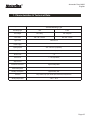
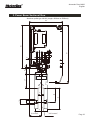
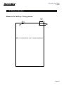
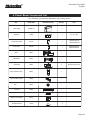
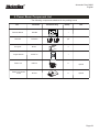
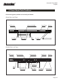
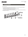
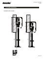
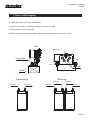
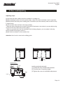
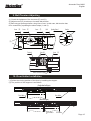
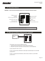
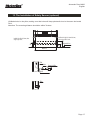
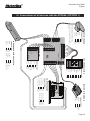
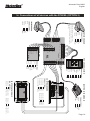
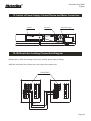
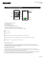
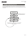
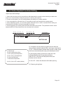
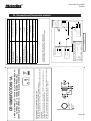
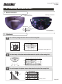
Automatic Door M200
English
AUTOMATIC DOOR
M200
(KAPV SP / KAPVE SP)
Instructions
Manual
PLEASE READ CAREFULLY BEFORE
ANY ASSEMBLY OR INSTALLATION
VER.: 1.2
REV.: 02/2014
Automatic Door M200
English
Content
Warning to installer and user
pg. 03
1. Characteristics & Technical Data
pg. 04
2. Power Beam Sectional View
pg. 06
3. Glass production
pg. 07
4. Power Beam Device Component List
pg. 08
5. Power Beam Parts Positions
pg. 10
6. Power Beam Installation
pg. 11
7. Door Leaf Hanging
pg. 13
8. Door Leaf Adjusting
pg. 14
9. Belt Tensioner Installation
pg. 15
10. Door Halter Installation
pg. 15
11. Connection Scheme
pg. 16
12. Emergency battery wiring scheme (optional)
pg. 16
13. The installation of safety sensor (optional)
pg. 17
14. Connections of all devices with the PCB ML
pg. 18
15. Switch of Power Supply, Control Device & Motor Connection
pg. 19
16. Bi-Doors Inter-locking Connection Diagram
pg. 19
17. Program selector diagram
pg. 20
18. Graphic: Programming control unit
pg. 21
19. Control System Functions Setting
pg. 22
20. Connections Photocells module
pg. 23
21. Connecting Microwave sensors
pg. 24
22. The abnormal status & the resolving methods
pg. 26
Page 02
Automatic Door M200
English
Warning to installer and user
1) WARNING: It´s very important to your safety that this instructions are followed.The bad installation
or wrong appliance can damage people or materials.
2) This product was designed and produced strictly for the use indicated in this manual. Any other
use then expressly mentioned may damage the product and / or be a hazard to people, and void the
warranty.
3) ELECTROCELOS is not responsible for the incorrect use of the product or by using other than that
for which it was designed.
4) Do not install the product in an area where there is danger of explosion: gases or flammable fumes
are a serious security threat.
5) ELECTROCELOS is not responsible if the safety standards weren´t taken into account in the
manufacture of the element to be automated, or any deformation that may occur at the same.
6) Before the installation, turn off the power.
7) The devices (ex: photocells) should be used for prevent injury in people or materials.
8) ELECTROCELOS is not responsible for safety and proper operation of the product when isn´t
used components sold by itself.
9) Do not make any changes to motor components and accessories.
10) The installer should inform the customer of how to operate the product in an emergency case
and provide the manual of it.
11) Do not let children closer to the door when in motion.
12) Keep controls out of reach of children, to prevent any accident.
13) You shouldn´t in any circumstances, attempt to repair or modify the equipment. Must call a
qualified technician for that job.
14) The equipment should be installed protected from elements such as: water, rain, humidity or
excessive dust.
15) Equipment must be connected to earth ground.
16) Equipment for indoor use only.
Page 03
Automatic Door M200
English
1. Characteristics & Technical Data
- Intelligent Automatic Door - Auto programmable and with adjustable parameters.
- Low noise level - Replaceable rubber guide base.
- Firm movement , ABS Braking - Virtually no noise.
- Auto reverse when hitting an obstacle.
- Unic electronic motor lock - Locking force of approximately 800N.
- Lower Power Consumption - Approximately 10W in Standby.
- 36V brushless motor - High efficiency, high strength and long life.
- Bi-Door Interlocking - One of the doors remains closed (interlock between doors).
- Program selector with 5 available functions: Fully closed, Fully open, Partial opening, Automatic,
Entry/exit only.
- Emergency Battery optional - Allows emergency opening in case of 230V power failure.
- Auxiliary functions - Compatible with most access control systems.
- Satin finish.
- Adapted for varied climates.
- Simple installation.
Objectives focused by the designer:
- Reverses automatically when hiting obstacle in the path - Security in first place.
- Move Steadily - Low noise level
Page 04
Automatic Door M200
English
1. Characteristics & Technical Data
Specification
Surface Mouting Type
Door Body Type
1 Leaf
2 Leafs
Door Weight
Max. 200Kg
Max. 100Kg/leaf
Door Width
DW = 700 ~ 2000mm
DW = 650 ~ 1500mm
Type of Use
Intensive Use
Power Supply
AC230V +/- 10%, 50 ~60Hz
Opening Speed
300 ~ 500 mm/s (Adjustable)
Closing Speed
250 ~ 500mm/s (Adjustable)
Bounce Time
< 1s
Pause Time
1 ~ 20s (Adjustable)
Airproof Force
> 70N
Electronic Lock Force
Approximately 800N
Motor Rated power
100W
Standby consumption
Approximately 10W
Functions
Fully closed, Fully open, Partial open, Automatic, Entry/exit only
Working Temperature
- 30º C ~ 50º C
Page 05
Automatic Door M200
English
2. Power Beam Sectional View
150
200
(In addition has the dimensions 170 to choose and match)
Aluminum profile type: M0103 (Length: 4200mm or 5800mm)
108
26
25
6
31
6
12
34
20
10
20
(28∼44 variable)
Until the center of the leaf
( Leaf movement )
Pag. 06
Automatic Door M200
English
3. Glass production
Measures
for drilling
/ Fixing glasses:
3. Produção
Vidro
Ø16
150
20
(We recommend the use of tempered glass)
Page 07
Automatic Door M200
English
4. Power Beam Component List
- The following components attached in the packing boxes
Item
Part Number
Schematic Drawing
Quantity
Note
Glass Profile
M PERFIL V
2
Batteries
M BAT
3
3 x 12V 1,2Ah
Power beam Model
M0103
1
Standard 4200mm
Standard 5800mm
Cover Profile
M0103T
1
Standard 4200mm
Standard 5800mm
Motor
M0901
1
Belt Tensioner
M0201
1
Cradle parts
M0401
4
Upper Connection Parts
M0501
1
Lower Connection Parts
M0502
1
Belt
M0301
1
Controller
M0802
Door Halter
M0601
4
M1201
1
M1601
2
Switch of power supply
Microwave Sensor
MOTORLINE
Normally 2pcs per door
1
Page 08
Automatic Door M200
English
4. Power Beam Component List
- The following components attached in the packing boxes
Item
Part Number
Schematic Drawing
Quantity
Note
GAIN / GANHOS
10% - 50%
FREQUENCY WORK
FREQUENCIA TRABALHO
1/2 f
Photocells Module
-
+
f
CR10MS
12 Volt
24 Volt
GAIN/GANHO 100%
GAIN/GANHO 50%
1
Photocells
Door guide
Program Selector
/ VERMELHO
/MALHA
/ BRANCO
/MALHA
LED
N.C. CONTACT
N.O. CONTACT
1par
FOTO9S1A
2
M2125
M CELE 01
2
1
FUNC
3
1
4
Electric Lock
M ELE 02
O
Optional
Electric lock controller
module
M FE 03
O
Optional
Page 09
Automatic Door M200
English
5. Power Beam Parts Positions
All mounting parts position are basically as follows:
(Single Door Leaf Type)
Lower Connection Parts(Right)
Upper Connection Parts(Left)
Belt Tensioner
Door Halter
Cradle Parts
Belt
Control Device
Motor Device
Switch of Power Supply
Door Halter
(Double Door Leaf Type )
Belt Tensioner
Upper Connection Parts
Lower Connection Parts
Control Device
Motor Device
OWNIC AUTO DOOR
Cradle Parts
Belt
Cradle Parts
Door Halter
Door Halter
Switch of Power Supply
Page 10
Automatic Door M200
English
6. Profile Installation
(Surface Mounting)
The surface must vertically and horizontally leveled to ensure the proper functioning condition.
- Set the M0103 profile to wall using at least 8mm screws
(1) Make holes in the profile and in the wall in order to fix power beam.
Use a level to verify that the profile is perfectly level.
(2) Pay attention to the passage of electrical cables and signal in order to prevent them from being
damaged by moving parts.
Profile
400
400
400
400
400
End cover
(Not Standard Configuration)
Cover
(Not Standard Configuration)
Page 11
Automatic Door M200
English
6. Profile Installation
5,7
25,25
2200
2200
200
235
POSSIBLE APPLICATIONS:
11
21
Page 12
Automatic Door M200
English
6.
Beam
Cutting
7. Power
Door Leaf
Hanging
To adjust the leaves, follow the steps below:
(1) Loosen the screw A to lower the support in relation to cradle
(2) Hang the door leaf in the profile
(3) Ensure that the nylon wheel of the cradle will roll down right along the curve track.
Cradle
Height adjustment screw (C)
Pressing Wheel
Screw (D)
Screw (D)
120
Door Top
(Bisection type)
(Single door leaf type)
Cradle parts
Cradle parts
Cradle parts
Screw (A)
Cradle parts
Cradle parts
Cradle parts
Page 13
Automatic Door M200
English
8.
Adjusting
7. Door
PowerLeaf
Beam
Installation
Adjusting steps:
(1) Left and right side cradles should be installed in a straight line.
(2) After hanging the door leaf on the power beam, check if the door leaf slides to left or right side.
(3) With the door leaf hung on the sliding guide, it should be open and close by hand in order to verify
if exists friction.
(4) The movable door leaf has to be hung vertically.
- When the space between the movable leaf and the fixed parts is not desired, you can adjust using
screws D from the cradle (See previous page).
- When the movable door leaf are declining as the following diagram, you can adjust it relieving
bolts A and B and turning the screw C.
(5) No friction is allowed on the movable door.
Attention: No oil can be used on the sliding guide.
Cracks
Cracks
Height adjustment screw (C)
Screw(B) (Up )
(Down)
Screw (D)
Leveling and adjusting leafs:
(1) Loosen the screws A and B from bracket.
(2) Turn the screw C to adjust height
(3) Tighten the screws A and B after adjustment.
Screw (D)
Screw (A)
Page 14
Automatic Door M200
English
Assembly:
9. Belt
Tension Adjusting
(1) Check the tightness of the 4 screws (F) and (G)
(2) Adjust screw (D) to reduce or increase belt tension.
(3) Belt may get prolonged after a long time of use. In this case, belt tension has
to be renewed by repeating the above steps (1 and 2).
Screw (D) Screw (E)
Screw (F)
(F)
Ajusting Panel
Belt
Limiter
A
(F)
Terminal
Screw (G)
Screw (H)
Switch of Power Supply
10. Door Halter Installation
(1) Define the closing position of the door by installing the stopper.
(2) The position of the stoppers is as follows.
(Single door leaf type)
Door Halter
Door Halter
(Bisection type)
OWNIC AUTO DOOR
Door Halter
Door Halter
Page 15
Automatic Door M200
English
11. Connection Scheme
!WARNING! : All the connections should be operated under cutting off the 230V power supply.
Partial-opening terminal
Do not use (For Future use only)
1 2 3 4 5 6 7 8
Function of Bi-door Inter-Locking
9 10 11 12 13 14 15 16
0V(Battery , Accessories)
+36V (Battery)
+15V (Accessoies power supply 600mA)
Control Device
M0802
Input for photocells (NC)
Full opening terminal
Common
Anti Panic Function
Do not use (For Future use only)
Note: Exit 6 and 7 are only for Anti Panic automatic glass doors. If not using
this function, place a shunt between the 2 exits.
20.
de ligação
central
e fechadura
electronica
12. Esquema
Emergency
battery entre
wiring
scheme
(optional)
Battery
0V
36VDC
Controller
9
10
The batteries are only for the following cases:
1 - Open the door automatically in case of 230V power failure.
2 - Electronic lock when closed, for a limited time in case of 230V fault.
For this select K2 ON or K2 OFF.
K2 ON - In the presence of batteries, door opens automatically in case of 230V
power failure.
K2-OFF - In the presence of batteries, door remains closed in case of 230V
power failure.
Page 16
Automatic Door M200
English
13. The Installation of Safety Sensor (optional)
(1) Make holes in the pillar, making sure that holes will keep photocells lens in the same horizontal
level.
Attention: The mounting distance should be within 7meters.
Installation height is 300mm & 900mm,
when using double circuit.
600
300
900
Installation height is 600mm, when
using single circuit.
Horizontal Line
Within 7m
Pillar
Fasten
Connection Wire
Guide
Pillar
Page 17
Automatic Door M200
English
14. Connections of all devices with the PCB ML (OPTION 1)
OUTSIDE RADAR
8
7
6
5
4
3 2 1
SELECTOR
LOCK
9
5
3
CONNECTIONS:
Grey
1
Brown
2
Orange
3
Purple
4
Blue
5
Green
6
White
7
Black
8
Red
9
PROGRAM SELECTOR
36V
SIGN
CONTROL
0V
15
14
RECEIVER
11
OSIG
10
LSIG
0V
COM
15V
15V
9
CONNECTIONS:
Red
oV
Red
15V
Yellow
NO
Yellow
COM
(the two yellow and red wires do
not have specific positions, as long
as they are connected like described
above)
RADAR EXT
0V
15V
NO
COM
ML
0V
NO
0V
RADAR INT
COM
CONNECTIONS:
12/24v
15V
0v
0V
CH1-a
OSIG
CH1-b
COM
0V
LSIG
CH2-b
MR5 CH2-a
MR5
RECETOR MR5
12/24v
0v
CH1-a
CH1-b
CH2-a
CH2-b
COM
nº1 Control
nº2 Control
INSIDE RADAR WITH PHOTOCELLS
CONNECTIONS:
Black
0V Green
Red
15V Yellow
White
NO Brown
11 ML
14 ML
15 ML
CONNECTIONS:
Yellow
SIGN
Red
36V
Green
0V
ELECTRIC LOCK MODULE
12 13 14 15 16
1 2 3 4 5 6 7 8
9 10 11
CONTROL BOARD
CONNECTIONS:
Control nº3
3 ML Control nº11
Control nº5
5 ML Control nº14
9 ML Control nº15
Control nº9
Control nº10
10 ML
Page 18
Automatic Door M200
English
14. Connections of all devices with the PCB ML (OPTION 2)
OUTSIDE RADAR
CONNECTIONS:
Red
oV
Red
15V
Yellow
NO
Yellow
COM
8
7
6
5
4
OSIG
9
3 2 1
SELECTOR
LOCK
9
5
3
CONNECTIONS:
Grey
1
Brown
2
Orange
3
Purple
4
Blue
5
Green
6
White
7
Black
8
Red
9
PROGRAM SELECTOR
36V
SIGN
CONTROL
0V
15
14
RECEIVER
0V
CONNECTIONS:
12/24v
15V
0v
0V
CH1-a
OSIG
CH1-b
COM
0V
LSIG
CH2-b
MR5 CH2-a
MR5
10
11
15V
15V
COM
LSIG
ML
0V
NO
12/24v
0v
CH1-a
CH1-b
CH2-a
CH2-b
RECETOR MR5
COM
0V
RADAR INT
COM
NO
15V
RADAR EXT
0V
(the two yellow and red wires do
not have specific positions, as long
as they are connected like described
above)
INSIDE RADAR
CONNECTIONS:
Red
oV
15V
Red
Yellow
NO
Yellow
COM
nº1 Control
nº2 Control
CONNECTIONS:
Yellow
SIGN
Red
36V
Green
0V
ELECTRIC LOCK MODULE
12 13 14 15 16
1 2 3 4 5 6 7 8
9 10 11
CONTROL BOARD
11 ML
14 ML
15 ML
Mod. nº3
Mod. nº4
1
2
3
4
5
6
7
8
CONNECTIONS:
Control nº3
3 ML Control nº11
Control nº5
5 ML Control nº14
9 ML Control nº15
Control nº9
Control nº10
10 ML
PHOTOCELL’S MODULE
CONNECTIONS:
Mod. nº1
nº9 Control
Mod. nº2
nº11 Control
Page 19
Automatic Door M200
English
15. Switch
of Power
Supply, Control Device and Motor Connection
11.
Belt Parts
Installation
Motor Device
Controller
Switch of Power Supply
16. Bi-Door Inter-Locking Connection Diagram
Double doors - After the closing of one door, another opens (Inter-Locking)
With this connection the 2 doors are never open at the same time.
Controller (M0802)
12 13 14
12 13 14
12-13
13-12
14-14
Page 20
Automatic Door M200
English
17. Program
diagram
11.
Belt Partsselector
Installation
5
Initialization Reset Button
Screw fixed hole
LED
Fully Open
Button
Fully Lock
Button
W IN F O R T E C H N O L O G Y
+V D D
Automatic
Button
FUNC
P R O G R A M S W IT C H F O R A U T O -D O O R
MO D E L :M -2 0 3 F
2
1
D C 12
G ND
AC C E S S
2
3
4
5
6
7
1
8
9
*
0
#
30V
O U T -S W
IN -S W
P US H
C OM
NO
Partial Open
Button
3
4
Unidirectional
Button
P C OM
P NO
Terminals
Screw fixed hole
(Frontal Panel)
(Back Panel)
• Five-range program selector
• DC15 power input
• Easy instalation and use
• Function switch against password
• With memory function in case of power failure
• Instruction with indicator light to confirm operation validity.
“FULLY LOCK”
“ FULLY OPEN”
6
“HALF OPEN” - Outdoor and indoor sensors are enabled - Door only half open
“UNIDIRECTIONAL ” - It allows to disable one of the microwave sensors according to direction
“AUTOMATIC” - Indoor and outdoor sensors are enabled.
Changing operation mode:
- Press the "FUNC" key for 5 seconds - Led indicator turns green - Enter password (original password is 1234).
Reconfirm by pressing the "FUNC" button again - Select the function you need from the five available FULL LOCK /
FULL OPEN / HALF OPEN / EXIT ONLY / AUTOMATIC.
Setting Management password:
- Press the "FUNC" key for 10 seconds - Selector will emit sound between 5 and 10s - Enter correct password.
Reconfirm by pressing the "FUNC" button again - Enter new password and press "FUNC", reconfirm the new password
and pressing "FUNC" key (New password setting completed successfully).
Note - If you have forgotten your password, open the rear panel and press the RESET button for 40 seconds.
The initialization of the system is confirmed by sounding a beep. Password back to 1234.
Page 21
Automatic Door M200
English
11.
Belt PartsProgramming
Installation control unit
18. Graphic:
(Bisection type)
After assembly completed, open and close the door several times by hand before connecting to
main power supply 230V in order to assure that there is no obstacle during opening and closing.
After checking the proper motion of the leaves, can now move to the programming, which is made
automatically.
With the door closed ,
connect to 230V power supply
Note: While doing this operation, do not
pass in front of the microwave sensors
Wait about 3 seconds
Door will open and close at low speed
Wait until door stops at close position
The control unit stores automatically
all process
In case of controller receives an order from sensor or obstacle
before finishing maneuver recognition, it will repeat the
whole process again
Page 22
Automatic Door M200
English
19.
System
Functions Setting
12. Control
Belt Tension
Adjusting
Adjust steps and warnings:
1. Open and close the door for several times with hands before turning on the electricity to make sure
there is no unconviniently during the process of opening and closing.
2. If there is safe power, you can enable/disable according to K2 switch position.
3. You must adjust the rebound force (F) according to door leaf’s weight and running speed.
4. When adjusting speed, you must also adjust rebound force in order to avoid the door taking for
meets barriers bounde to present repeatedly movement.
5. At the beggining, the opening time should be selected to the mínute. This parameter will be easier
adjusted after the other parameters have already been selected.
A B
C
D E
F
K1 K2 K3
K4
Controller M0802
MOTORLINE
A - Indicator light
B - Hand handling button (Start)
C - Door opening speed adjustment
D - Door closing speed adjustment
E - Pause time adjustment
F - Rebound force adjustment
K1, K2, K3, K4 in OFF condition (default)
K1. K1 button in ON, by receiving signal from the radar, the
door will open and only will close after receiving a second pulse.
K1 OFF - Automatic Mode: The door opens to the 1st radar signal
and closes automatically after expiry preselected pause time.
K2. If emergency battery present, the switch K2 in ON
will keep the door open in case of power failure
230V. K2 OFF, in the event of 230V power failure, the
the door remains closed.
K3. ON / OFF - Selects the direction of the door opening.
K4. Choosing closing force.
Page 23
11
Foro Lamiera/
Hole Leaf /
Furo Folha
GAIN/GANHO 50%
GAIN/GANHO 100%
f
1/2 f
FREQUENCY WORK
FREQUENCIA TRABALHO
VERS. 1.3
N.O. CONTACT
N.C. CONTACT
LED
-
24 Volt
12 Volt
+
GAIN / GANHOS
10% - 50%
89 / 336 / CEE; UNI 8612
INFRARED / INFRAVERMELHOS 900 nm
1A - 24 Volt DC
N.O. / N.C. (RELAY CONTACT / CONTACTO RELÉ)
-15 ÷ +50° C
50 mA
12 / 24 Volt DC - AC ± 15%
IP 30 ( IP 55 OPTIONAL / OPCIONAL)
0,1 ÷ 6 mt.
APPLICAZIONI / APPLICATIONS / APLICAÇÕES:
Porte automatiche / Automatic doors / Portas Automáticas
/MALHA
DESCRIZIONE / DESCRIPTION / DESCRIÇÃO :
CR10MS è una fotocellula per la gestione di 1 raggio infrarosso.
L'elettronica, progettata con circuito PLL, garantisce un'ottima immunità da disturbi ottici ed elettrici.
CR10MS is a control unit for 1 infrared beam. PLLelectronic circuit guarantees an excellent immunity to optical and electrical noise.
CR10MS é uma unidade de controlo para um feixe de infravermelhos.Circuito eletrônico
PLL garante uma excelente imunidade ao ruído óptico e eléctrico.
CONFORMITÀ/APPROVALS / CONFORME
RAGGIO/OPTICAL RAY/ FEIXE ÓPTICO
PORTATA CONTATTO/OUTPUT CONTACT/
SAÍDA CONTACTO
USCITA/OUTPUT/SAIDA
/ BRANCO
MADE IN ITALY
TEMPERATURA DI FUNZIONAMENTO/
OPERATING TEMPERATURE /
TEMPERATURA DE FUNCIONAMENTO
ASSORBIMENTO/SUPPLY CURRENT
CURRENTE/
ALIMENTAZIONE/SUPPLY VOLTAGE /
ALIMENTAÇÃO
/ VERMELHO
UNITÀ DI CONTROLLO - FOTOCELLULA SINCRONIZZATA
CONTROL UNIT - SYNCHRONIZED PHOTOCELL
CENTRAL DE CONTROLO - FOTOCÉLULAS SINCRONIZADAS
PROTEZIONE/DEGREE OF PROTECTION/
GRAU DE PROTECÇÃO
PORTATA/RANGE/ALCANCE
/MALHA
CR10MS/FOTO9S1A
CARATTERISTICHE TECNICHE / TECHNICAL DATA / DADOS TÉCNICOS
Automatic Door M200
English
20. Connections
14.
Motor DevicePhotocells
Installationmodule
Page 24
Automatic Door M200
English
21. Connecting Microwave sensors
1 General information
Sensitivity potentiometer
LED - flashes after power-on
- lights up during detection
JST-connector
Red
12-24V Power Supply
Yellow
Relay (COM)
Relay (NO)
Planar antenna
for wide detection field
2 Adjustments
1
The sensitivity settings determine the size of the sensing field
3
M IDDLE
1.5
0
1.5
M AX
MI N
3
vertical angle: 30°, mounting height: 2.2m
4.5
2
The lateral angle of the planar antenna determines the position of the sensing field
4.5
3
1.5
0
1.5
3
4.5
1.5
3
4.5
3
The vertical angle of the planar antenna determines the depth of the sensing field
3
0° 15°
15°
30°
45°
45°
30°
1.5
1.5
0
1.5
3
15°
3
30°
4.5
45°
sensitivity: maximum
Page 25
Automatic Door M200
English
21. Connecting Microwave sensors
3 Installation tips
Avoid vibrations!
Do not cover the
sensor!
Avoid moving objects in
proximity of the sensor!
Avoid HF lamps or
fluorescent lighting in
proximity of the sensor!
Avoid touching
electronics!
Revolve the
potentiometer slowly
with small strength.
4 Troubleshooting
SYMPTOMS
The door will not open and no red LED
lights up.
PROBABLE CAUSES
The sensor power is off.
CORRECTIVE ACTION
Check the wiring and the power supply.
The door opens and closes constantly.
The sensor "sees" the door moving.
Increase the tilt angle and/or reduce the sensitivity.
When closing, the door creates
vibrations picked up by the sensor.
Make sure that the sensor is correctly fixed.
Reduce the sensitivity.
ON-OFF switch at door control is in
wrong position or faulty.
Improper output configuration.
Make sure that the ON-OFF switch for the door is in the ON or
AUTOMATIC position. Check the output configuration setting
on each sensor connected to the door operator.
The door will not close.
Red LED is OFF.
5 Technical specifications
Technology
Transmitter frequency
Transmitter radiated power
Transmitter power density
Maximum mounting height
Tilt angles
Detection field (mounting height=2.2m)
Detection mode
Minimum speed
Supply voltage
Mains frequency
Power consumption
Output relay (free of potential change-over contact)
Max. contact voltage
Max. contact current
Max. switching power
Hold time
Temperature range
Degree of protection
Norm Conformity
Material
Color of housing
Dimensions
Weight
Length of cable
: microwave and microprocessor
: 24.125GHz
: <20dBm EIRP
: <5mW/cm²
: 3.5 m
: 0° to 90° vertical and -30° to + 30° lateral
: 6m (W) x 3m (D)
: motion
: 5 cm/s (measured in the sensor axis)
: 12V to 30V AC/DC +30% / -10%
: 50 to 60 Hz
: < 2W (VA)
: 42V AC- 60V DC
: 1A (resistive)
: 30W (DC) / 60VA (AC)
: 1.0 s
: -25°C to +55°C
: IP54
: R&TTE 1999/5/EC; EMC 89/336/EEC
: ABS
: black smoked, aluminium finish
: 120mm (W) x 80mm (H) x 50mm (D)
: 0.265kg
: 2.5m
Page 26
Automatic Door M200
English
22. The Abnormal Status and the Resolving Methods
When the auto-door unconventionally runs, please cut off the power supply for a few seconds, and
then turn on again.
Nº
Abnormal Status
1
The door cannot
move
2
Door open and close
with very low speed
3
Door cannot be closed
4
5
Door reverse direction
when closing
Door leafs slam
violently
Possible cause
1. Power failure
2. Door blocked
3. Damaged fuse
4. Cables desconnected
1. Leafs with friction
2. Cradels with damaged bearings
3. M0201Group tensioner with damaged
bearings
4. Defective control unit
5. Motor with stuck reducer
1. Sensor sending continued signal
2. Photocells always open
1. There are obstacles in the sensor detection
area.
2. The door leaves are within the detection
area.
3. Photocells misaligned
4. There is friction in some door components
- Lack of stoppers
- Faulty control board
Resolving Methods
1. Check the 230V power supply.
2. Separate the door from belt and check if
door can be moved by hand
3. Check fuse M1201
4. Make sure the cables are securely connected
1. Move the door manually, without
being attached to belt and verify proper operation.
2. Repeat the previous step
3 Remove belt and check by hand if the
movement is correct.
4.Change the position of the potentiometers D and C
see whether the unit changes the operation.
5. Without the belt and without power, make sure the
motor turns manually
1.Unplug one radar ,one by one to see if the door
close
2. Check if the cables connecting photocells module
to control unit (1 and 2) close the circuit NO.Install
an shunt between point 1 and 2 and make sure the
door close.In case it closes verify power suplly cables
1. Remove obstacles in the area of the detection
sensor.
2. Adjust the sensor detection area and sensitivity
3. Align the photocells
4. Check, moving leaves by hand, where
exists contact between components
- Check if the stoppers are tight and in place;
- Change the position of the potentiometers C
and D in order to see whether the switch changes
control unit operation.
- Reset control board by disconnecting batteries and
230V power supply for 5seconds.Power
on again, the door will start new programming.
Page 27


![[17] User`s Manual ver. 2.0.2](http://vs1.manualzilla.com/store/data/005765389_1-e376d351ef2708f30fcfdc5f98b9ba18-150x150.png)