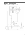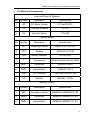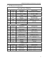
1
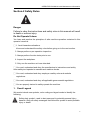
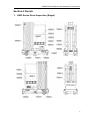
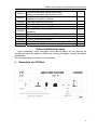
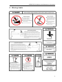
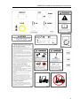
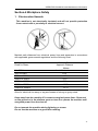
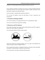
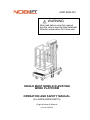
AWP-SMS-001 WARNING
Must read before using this manual
And the various warning label attached!
Attention preservation for future use!
SINGLE MAST MOBILE ELEVATING
WORK PLATFORM
OPERATION AND SAFETY MANUAL
(For AWP6/AWP8/AWP10)
Original lssue of Manual Version 07/2013 OPERATOR’S MANUAL with Maintenance information
Important
Read, understand and obey these safety rules and operating instructions
before operating this machine.
Only trained and authorized personnel shall be permitted to operate this
machine. This manual should be considered a permanent part of your
machine and should remain with the machine at all times. If you have any
questions, please call us.
Owners, Users and operators:
We appreciate your choice of our machine for your application. Our number one
priority is user safety, which is best achieved by our joint efforts. We feel that you
make a major contribution to safety if you, as the equipment users and operators:
1.
2.
3.
4.
Comply with employer, job site and governmental rules.
Read, understand and follow the instructions in this and other manuals
supplied with this machine.
Use good safe work practices in a commonsense way.
Only have trained / certified operators, directed by informed and
knowledgeable supervision, running the machine.
If there is anything in this manual that is not clear or which you believe should be
added, please contact us.
1
OPERATOR’S MANUAL with Maintenance information
Revision Log
Original Issue of Manual…………………………………………………July 2013
2
OPERATOR’S MANUAL with Maintenance information
Contents
Section -1 Specifications ......................................................................................... 5
Section-2 Safety Rules ........................................................................................... 6
1. Decal Legend ....................................................................................... 6
2. Intended Use ....................................................................................... 7
3. Maintenance Labels ............................................................................. 7
4. Operator............................................................................................... 7
Section-3 Decals ..................................................................................................... 8
1. AWP Series Decal Inspection (Single) ................................................. 8
2. Decals Table ........................................................................................ 9
3. Nameplate and CE Mark.................................................................... 10
4. Warning Labels ................................................................................... 11
Section-4 Workplace Safety .................................................................................. 14
1. Electrocution Hazards ........................................................................ 14
2. Tip-Over Hazards ................................................................................. 15
3. Fall Hazards ......................................................................................... 17
4. Collision Hazards ................................................................................. 17
5. Component Damage Hazards .............................................................. 18
6. Explosion and Fire Hazards ................................................................. 18
7. Damaged Machine Hazards ................................................................. 19
8. Crushing Hazards ................................................................................. 19
9. Bodily Injury Hazard ............................................................................. 19
10. Outrigger Safety ................................................................................. 19
11. Battery Safety ..................................................................................... 20
Section-5 Control Panel ........................................................................................ 21
1. Control Panel function and Description .............................................. 21
2. How to use the control buttons .......................................................... 23
3. Installation of Power Plug .................................................................. 23
4. Emergency Operation ........................................................................ 23
Section-6 Pre-operation Inspection ....................................................................... 24
1. Fundamentals .................................................................................... 24
2. The relevant conditions of using the equipment ................................. 25
3. Pre-operation Inspection .................................................................... 25
Section-7 Maintenance ......................................................................................... 27
1. Periodical examinations and tests...................................................... 27
2. Check the Batteries............................................................................ 28
3. Battery charging ................................................................................. 28
4. Hydraulic Maintenance ...................................................................... 29
1) Adjusting the maximum rising force ................................................... 29
2) Adjusting the speed of falling ............................................................. 30
5. Check the Hydraulic Oil Level ............................................................ 30
6. Replacing the hydraulic oil ................................................................. 30
3
OPERATOR’S MANUAL with Maintenance information
7. Control check ..................................................................................... 31
8. Regulating the transmission chain ..................................................... 31
9. Lubricate ............................................................................................ 33
Section-8 Function Tests ....................................................................................... 33
1. Fundamentals .................................................................................... 33
2. Function Tests .................................................................................... 34
Section-9 Workplace Inspection............................................................................ 35
1. Fundamentals .................................................................................... 35
2. Workplace Inspection......................................................................... 35
Section-10 Operating Instructions ...................................................................... 36
1. Fundamentals .................................................................................... 36
2. Inspection on Opening the Packaging ............................................... 36
3. Area Needed For Set up the Machine................................................ 37
4. Leveling the whole equipment ........................................................... 38
5. How to use the control Buttons .......................................................... 39
6. Emergency Operation ........................................................................ 39
Section-11 Transport and Storage......................................................................... 40
1. Moving the equipment........................................................................ 40
2. Securing to Truck or Trailer for Transit ............................................... 41
3. Storage of the equipment ................................................................... 41
Section-12 Trouble shooting ................................................................................. 42
Section-13 Electrical Schematic ......................................................................... 43
1. Electrical Schematic of AC power supply ........................................... 43
2. AC Electrical Component ................................................................... 44
3. Electrical Schematic of DC power supply .......................................... 45
4. DC Electrical Components ................................................................. 46
Section-14 Hydraulic Diagram .............................................................................. 47
Section-15 Log ...................................................................................................... 48
4
OPERATOR’S MANUAL with Maintenance information
Section -1 Specifications
Technical specifications and major dimensions are shown in Table and
Figure, respectively.
The
Power
number
Model
Max.
Max.
Platform
Working
height height Rated
Load rating
of
Platform
Outrigger
Stored
persons
size
footprint
dimension
allowed
AxB
CxD
AC
LxWxH
DC
Machine
weight
on
platform
mm
mm
kg
Person(s)
mm
mm
Kw
mm
kg
AWP6
6000
8000
150
1
690 x 660
1940 x 1840
0.75
1.5
1420 x 776 x 1910
401
AWP8
8000
10000
125
1
690 x 660
1940 x 1840
0.75
1.5
1420 x 776 x 1930
430
AWP10
10000
12000
125
1
690 x 660
1940 x 1840
0.75
1.5
1420 x 776 x 1930
471
The following shows main
component parts:
1-Mast
2-Stay bar
3-Electric box
4-Chassis
5-Turning stabilizers of the unit
6-Non-steer tire
7-Platform
8-Steer tire
9-Motor protective cover
10-Control panel on work platform
11-Lifting Jack
5
OPERATOR’S MANUAL with Maintenance information
Section-2 Safety Rules
Danger
Failure to obey the instructions and safety rules in this manual will result
in death or serious injury.
Do Not Operate Unless:
You learn and practice the principles of safe machine operation contained in this
operator’s manual.
□ 1. Avoid hazardous situations.
Know and understand the safety rules before going on to the next section.
2. Always perform a pre-operation inspection.
3. Always perform function tests prior to use.
4. Inspect the workplace.
5. Only use the machine as it was intended.
□ You read, understand and obey the manufacturer’s instructions and safety
rules-safety and operator’s manuals and machine decals.
□ You read, understand and obey employer’s safety rules and worksite
regulations.
□ You read, understand and obey all applicable governmental regulations.
□ You are properly trained to safety operate the machine.
1.
Decal Legend
We product decals use symbols, color coding and signal words to identify the
following:
Safety alert symbol—used to alert personnel to potential personal injury
hazards. Obey all safety messages that follow this symbol to avoid possible
injury or death.
6
OPERATOR’S MANUAL with Maintenance information
Red—used to indicate the presence of an imminently
hazardous situation which, if not avoided, will result in death or serious injury.
Orange—used to indicate the presence of a potentially
hazardous situation which, if not avoided, could result in death or serious injury.
Yellow with safety alert symbol—used to indicate the presence
of a potentially hazardous situation which, if not avoided, may cause minor or
moderate injury.
Blue without safety alert symbol—used to indicate the
presence of a potentially hazardous situation which, if not avoided, may result in
property damage.
2.
Intended Use
Single mast mobile elevating work platform is intended to move one person
along with the necessary tools and materials to working position where he
will carry out work on the work platform.
3.
Maintenance Labels
Please instead the loosed or bad labels.
Wash the labels with neutral soap or limpid water.
Don’t use the deliquescent cleanser to wash the labels.
4.
Operator
Only the trained and qualified are permitted to operate this machine. Always use
safety belt and helmet when aerially working.
If you are subject to dizziness or seizures, or are bothered by heights, you must not
operate this type of machinery.
An operator must not use drugs or alcohol that can change his/her alertness or
coordination.
An operator on prescription or over-the -counter drugs needs medical advice on
whether or not he/she can safety operate machines.
7
OPERATOR’S MANUAL with Maintenance information
Section-3 Decals
1.
AWP Series Decal Inspection (Single)
8
OPERATOR’S MANUAL with Maintenance information
2.
Decals Table
Use the pictures on the next page to verify that all decal are legible and in place.
Below is a numerical list with quantities and descriptions.
Part No.
Description
QTY.
1009002
The travel switch warning label
1
1009024
Warning-shearing danger, keep hands away
1
1609008
Safety belt fixed point
1
Danger—Keeping safe clearance with live electric
1009003
1
conductors
1009004
Collision Hazards
1
1009006
Tip-over Hazards
1
1009007
Tilt the warning
1
1009019
Notice- Please cut off the power after operating(For DC)
1
1009021
DC control panel
1
1009020
Leveling and justment
2
1009023
Leveling and justment
2
1109010
Prohibition of forklift transport label
2
1009001
Machinery label
1
1009013
Danger-Collision hazards or Tip-over hazard
1
1109015
Forklift transport label
2
1609002
Label-fastness location
4
1009011
Max. Allowed wind speed-10.7m/s
1
1009012
Maximum load warning label
1
1009009
Fall hazards warning label
1
Warning-The manual forces applied by persons on the
1009008
work platform should not exceed the permitted limit
1
when it is raised
1009027
Brief operating instruction
1
9
OPERATOR’S MANUAL with Maintenance information
1009014
1009015
1109008
1609007E
1009018
1009025
1009026
1009017
1009028
1009022
Maximum allowable manual force 200N
Maximum allowable wind speed 10.7m/s
Maximum capacity 125kg,
Maximum occupancy 1 person
Warning-Operating Instruction
Battery maintenance warning label
Battery replacement warning label
Warning-Make sure to position the stabilizers before
operating
Max. Load on each stabilizer-2800N
Please don't stand
Caution-Electrocution hazard
Notice-The charging socket of the battery(For DC)
1
1
1
1
1
2
2
1
1
1
Plates and Warning Labels
Upon unpacking, check the plates and warning labels. Do not operate the
machine on which the plates or labels are missing or illegible. Contact the dealer
immediately.
The following plates are visible on the machine.
3.
Nameplate and CE Mark
10
OPERATOR’S MANUAL with Maintenance information
4.
Warning Labels
11
OPERATOR’S MANUAL with Maintenance information
12
OPERATOR’S MANUAL with Maintenance information
13
OPERATOR’S MANUAL with Maintenance information
Section-4 Workplace Safety
1.
Electrocution Hazards
This machine is not electrically insulated and will not provide protection
from contact with or proximity to electrical current.
Maintain safe distances from electrical power lines and apparatus in accordance
with applicable governmental regulations and the following chart.
Voltage
Phase to Phase
0 to 300V
300V to 50KV
Minimum Safe
Approach Distance
Meters
Avoid Contact
3.05
50KV to 200KV
4.60
200KV to 350KV
6.10
350KV to 500KV
7.62
500KV to 750KV
10.67
750KV to 1000KV
13.72
Allow for electrical line sway or sag and beware of strong or gusty winds.
Keep away from the machine if it contacts energized power lines. Personnel
on the ground or in the platform must not touch or operate the machine until
energized power lines are shut off.
Do not operate the machine during lightning or storms.
Do not use the machine as a ground for welding .
14
OPERATOR’S MANUAL with Maintenance information
2. Tip-Over Hazards
Occupants, equipment and materials must not exceed the maximum
platform capacity.
Maximum capacity
Maximum occupants 1
Do not raise the platform unless the machine is on a firm, level surface.
Do not move the machine when the platform is raised.
Do not raise the platform when wind speeds may exceed 10.7 m/s. If wind speeds
exceed 10.7 m/s when the platform is raised, lower the platform and do not continue
to operate the machine.
Do not operate the machine in strong or gusty winds. Do not increase the surface
area of the platform or the load. Increasing the area exposed to the wind will
decrease machine stability.
Use extreme care and slow speeds while moving the machine in the stowed
position across uneven terrain, debris, unstable or slippery surfaces and near holes
and drop-offs.
Do not use the machine as a crane.
Do not place or attach fixed or overhanging loads to any part of this machine.
Do not push the machine or other objects with the platform.
Do not contact adjacent structures with the platform.
Do not alter or disable the limit switches.
Do not push off or pull toward any object outside of the platform.
15
OPERATOR’S MANUAL with Maintenance information
Maximum allowable side force
200N
Do not tie the platform to adjacent structures.
Do not place loads outside the platform perimeter.
Do not alter or disable machine components that in any way affect safety and
stability.
Do not modify or alter an aerial work platform without prior written permission from
the manufacturer. Mounting attachments for holding tools or other materials onto
the platform, toe boards or guard rail system can increase the weight in the platform
and the surface area of the platform or the load.
Do not replace items critical to machine stability with items of different weight or
specification.
Do not place ladders or scaffolds in the platform or against any part of this machine.
Do not transport tools and materials unless they are evenly distributed and can be
safely handled by person(s) in the platform.
Do not use the machine on a moving or mobile surface or vehicle.
Be sure all tires are in good condition, air-filled tires are properly inflated and lug
nuts are properly tightened.
Do not drive the machine on a slope that exceeds the slope and side slope rating of
the machine.
Slope rating applies to machine in the stowed position.
16
OPERATOR’S MANUAL with Maintenance information
3. Fall Hazards
The guard rail system provides fall protection. If occupant(s) of the platform are
required to wear personal fall protection equipment(PFPE)due to job site or
employer rules, PFPE equipment and its use shall be in accordance with the PFPE
manufacturer’s instructions and applicable governmental requirements.
Do not sit, stand or climb on the platform guard rails. Maintain a firm footing on the
platform floor at all times.
Do not climb down from the platform when raised.
Keep the platform floor clear of debris.
Close the entry gate before operating .
4. Collision Hazards
Be aware of limited sight distance and blind spots when driving or operating.
Operators must comply with employer, job site and governmental rules regarding
use of personal protective equipment.
Check the work area for overhead obstructions or other possible hazards.
17
OPERATOR’S MANUAL with Maintenance information
Be aware of crushing hazards when grasping the platform guard rail.
Do not operate a machine in the path of any crane or moving overhead machinery
unless the controls of the crane have been locked out and/or precautions have
been taken to prevent any potential collision.
No stunt driving or horseplay while operating a machine.
Do not lower the platform unless the area below is clear of personnel and
obstructions.
5. Component Damage Hazards
Do not use any battery or charger greater than 12V to jump-start the engine.
Do not use the machine as a ground for welding.
6. Explosion and Fire Hazards
Do not start the engine if you smell or detect liquid petroleum gas (LPG), gasoline,
diesel fuel or other explosive substances.
Do not refuel the machine with the engine running.
Refuel the machine and charge the battery only in an open, well-ventilated area
away from sparks, flames and lighted tobacco.
Do not operate the machine in hazardous locations or locations where potentially
flammable or explosive gases or particles may be present.
Do not spray ether into engines equipped with glow plugs.
18
OPERATOR’S MANUAL with Maintenance information
7. Damaged Machine Hazards
Do not use a damaged or malfunctioning machine.
Conduct a thorough pre-operation inspection of the machine and test all functions
before each work shift. Immediately tag and remove from service a damaged or
malfunctioning machine.
Be sure all maintenance has been performed as specified in this manual and the
appropriate service manual.
Be sure all decals are in place and legible.
Be sure the operator’s, safety and responsibilities manuals are complete, legible
and in the storage container located in the platform.
8. Crushing Hazards
Keep hands and limbs out of scissors.
Use common sense and planning when operating the machine with the controller
from the ground. Maintain safe distances between the operator, the machine and
fixed objects.
9. Bodily Injury Hazard
Always operate the machine in a well-ventilated area to avoid carbon monoxide
poisoning.
Do not operate the machine with a hydraulic oil or air leak. An air leak or hydraulic
leak can penetrate and/or burn skin.
Improper contact with components under any cover will cause serious injury. Only
trained maintenance personnel should access compartments. Access by the
operator is only advised when performing a pre-operation inspection. All
compartments must remain closed and secured during operation.
10. Outrigger Safety
Do not lower the outriggers unless the machine is on a firm surface. Avoid drop-offs,
holes, unstable or slippery surfaces and other possible hazardous conditions.
19
OPERATOR’S MANUAL with Maintenance information
Do not raise the platform unless the machine is level. Do not set the machine up on
a surface where it cannot be leveled using only the outriggers.
Do not raise the platform unless all four outriggers are properly lowered, the
footpads are in firm contact with the ground and the machine is level.
Do not adjust the outriggers while the platform is raised.
Do not drive while the outriggers are lowered.
11. Battery Safety
1)
Burn Hazards
Batteries contain acid. Always wear protective clothing and eye wear when working
with batteries.
Avoid spilling or contacting battery acid.
Neutralize battery acid spills with baking soda and water.
2)
Explosion Hazard
Keep sparks, flames and lighted tobacco away from
batteries. Batteries emit explosive gas.
20
OPERATOR’S MANUAL with Maintenance information
3)
Electrocution Hazard
Avoid contact with electrical terminals.
Section-5 Control Panel
1.
Control Panel function and Description
1)
AC Control Panel
Control panel on electric box
21
OPERATOR’S MANUAL with Maintenance information
Control panel on work platform
1.
2.
3.
4.
2)
Leakage breaker
Circuit breaker
key switch
Power indicator
5. Up button
6. Down button
7. Red Emergency Stop button
DC Control Panel
1. Voltage indicator
2. On/Off key
3. Fuse
4. Emergency stop switch
5. Up button
6. Down button
22
OPERATOR’S MANUAL with Maintenance information
2.
How to use the control buttons
1. Before operating the machine, all circuit breakers and leakage breaker must be
in “ON” position on the electrical box panel.
2. The mobile elevating work platform has two sets of controls; one at the base of
the unit and the other on the work platform itself.
3. On either control panels, press “UP” button for lifting and press “DOWN” button
for lowering the platform.
4. The platform will be raised or lowered so long as the appropriate button is
depressed. The platform will stop in position as soon as the button is released.
5. Emergency stop: A big mushroom-shaped button is provided at each control
panel for emergency stop. This should be used only when other means to stop
the platform moving fails. Reset the button by turning the knob in the direction
shown by the arrow. Do not pull the knob.
The lower controls is installed on the electrical box, control
its key. The key should be taken away if it is not in use so as
to prevent the unauthorized personnel from using it.
3.
Installation of Power Plug
Put the power plug into the power socket at the job site in accordance.
Prior to installation, the rating of the power source must be
confirmed.
4.
Emergency Operation
In the event of power cut-off or other reasons and the platform fails to descend
using both the upper and lower controls, a knob consisting used to lower the
platform. Pull the knob and the platform will be lowered slowly.
The above shows the diagram of the knob.
23
OPERATOR’S MANUAL with Maintenance information
Section-6 Pre-operation Inspection
Do Not Operate Unless:
□ You learn and practice the principles of safe machine operation contained in this
operator’s manual.
1. Avoid hazardous situations.
2.
Always perform a pre-operation inspection.
Know and understand the pre-operation inspection before going on to the
next section.
3.
Always perform function tests prior to use.
4.
Inspect the workplace.
5.
Only use the machine as it was intended.
1.
Fundamentals
It is the responsibility of the operator to perform a pre-operation inspection and
routine maintenance.
The pre-operation inspection is a visual inspection performed by the operator prior
to each work shift. The inspection is designed to discover if anything is apparently
wrong with a machine before the operator performs the function tests.
The pre-operation inspection also serves to determine if routine maintenance
procedures are required. Only routine maintenance items specified in this manual
may be performed by the operator.
Refer to the list on the next page and check each of the items.
If damage or any unauthorized variation from factory delivered condition is
discovered, the machine must be tagged and removed from service.
Repairs to the machine may only be made by a qualified service technician,
according to the manufacture’s specifications. After repairs are completed, the
24
OPERATOR’S MANUAL with Maintenance information
operator must perform a pre-operation inspection again before going on to the
function tests.
Scheduled maintenance inspections shall be performed by qualified service
technicians, according to the manufacture’s specifications and the requirements
listed in the responsibilities manual.
2.
The relevant conditions of using the equipment
Using the equipment
□ The surface of work ground should be flat and hard with no obstacles in air
and the safety distance between the equipment and high-tension line is
adequate.
□ The environment temperature should be within -10℃~38℃; Height above
sea level ≤ 1000m.
□ The environment humidity ≤ 90%.
□ Electrical power : AC 230V±10%,50Hz.
□ The wind power is not more than Beaufort Scale 5
(the speed of wind is 10.7 m/s).
□ The noise grade of this machine is 72~74 dB while operation.
Prevent the sunlight from directly shining onto the hydraulic
and electrical units of the equipment if the environment
temperature is above 32℃.
If the conditions mentioned above are not met, please contact with your supplier
and take the relevant guarantee measures for using the equipment.
3.
Pre-operation Inspection
Before you begin your workday, you must inspect your machine and report all
deficiencies. Do not operate the machine until deficiencies are corrected and all
systems are in good operational condition.
□ Be sure that the operator’s, safety and responsibilities manuals are complete,
legible.
□ Be sure that all decals are legible and in place. See Decals section.
□ Check for hydraulic oil leaks and proper oil level. Add oil if needed. See
Maintenance section.
25
OPERATOR’S MANUAL with Maintenance information
□ Check for battery fluid leaks and proper fluid level. Add distilled water if needed.
See Maintenance section.
Check the following components or areas for damage, improperly installed or
missing parts and unauthorized modifications:
□ Electrical components, wiring and electrical cables
□ Hydraulic hoses, fittings, cylinders and manifolds
□ Fuel and hydraulic tanks
□ Drive motors
□ Wear pads
□ Tires and wheels
□ Limit switches
□ Nuts, bolts and other fasteners, especially the screws and nuts on both sides of
the masts.
□ Platform overload components
□ Platform entry gate
□ Beacon and alarms (if equipped)
□ Generator (if equipped)
Check entire machine for:
□ Cracks in welds or structural components
□ Dents or damage to machine
□ Be sure that all structural and other critical components are present and all
associated fasteners and pins are in place and properly tightened
□ Check if there is an abnormal noise or tremble when starting the machine
□ Secure connection of power or battery plug.
□ Perform necessary maintenance procedure outlined by the manufacture.
26
OPERATOR’S MANUAL with Maintenance information
Section-7 Maintenance
Observe and Obey:
□ Only routine maintenance items specified in this manual shall be performed by
the operator.
□ Scheduled maintenance inspections shall be completed by qualified service
technicians, according to the manufacturer’s specifications and the requirements
specified in the responsibilities manual.
Maintenance Symbols Legend
The following symbols have been used in this manual to help communicate
the intent of the instructions.
When one or more of the symbols appear at the beginning of a maintenance
procedure, it conveys the meaning below.
Indicates that tools will be required to perform this procedure.
Indicates that new parts will be required to perform this procedure.
1.
Periodical examinations and tests
This GTWP should be examined and tested according to the following items every 3
months.
1. Lubricate the lifting chain. Check the chain for wear.
2. Check and tighten possible loose screws and nuts.
3. Check brush wear in the pump motor, and replace those worn so that a good
contact is maintained.
4.
Visual examination of the structure with special attention to corrosion and other
damage of load-bearing parts and welds.
5. Examination of the mechanical, hydraulic, and electrical systems with special
attention to safety devices.
27
OPERATOR’S MANUAL with Maintenance information
The frequency and extent of periodical examinations and tests may also
depend on national regulations.
2.
Check the Batteries
Proper battery condition is essential to good engine performance and
operational safety. Improper fluid levels or damaged cables and connections can
result in engine component damage and hazardous conditions.
They must be checked at least once a week
Electrocution hazard
Contact with hot or live circuits may result in death or serious injury. Remove all
rings, watches and other jewelry.
Bodily injury hazard
Put on protective clothing and eye wear.
The terminal connections must be firmly tightened and greased with acid-free
grease, which prevents sulphate formations. Sulphate coating reduces the contact
surface, resulting in a considerable voltage.
Be sure that the battery hold-down bars are secure.
Terminal points must be free of scale. Cable insulation must be in good condition.
Remove the battery vent caps. Check the battery acid level. If needed, replenish
with distilled water to the bottom of the battery fill tube. Do not overfill. Avoid spilling
or contacting battery acid. Neutralize battery acid spills with baking soda and water.
If skin or clothes come into contact with this acid wash with abundant soap and
water.
The battery surface must be kept clean and dry, as dirt and wet will cause leakage
of current and consequently reduced battery capacity.
3.
Battery charging
1. Turn the key and switch on, when the display indicated voltage is below 11 volt,
please charge up the battery.
2 . The rated specification of the battery charger supplied:
Input: 220V AC50/ 60Hz
Output: 12V DC 15A
28
OPERATOR’S MANUAL with Maintenance information
3. When start charging, insert the output plug of the charger to the charging socket
of the chassis first, then the input plug of the charger to the socket of AC power
supply. Turn on the charger switch; battery charging is started with indicator (red
lamp) lights up. Normal recharging lasts about 10 hours. When charging is
terminated check that all cells have reached a density between
1.260~1.280kg/I at 30℃. When charge is finished, the AC supply should be cut off.
4. Battery charging should be done in a well-ventilated place and there are no
naked flames, no sparks and no heat radiation sources nearby.
5. Make sure the level of the electrolyte is above the lower line. If the elements are
not covered, top up with distilled water. Under normal conditions topping up can be
generally done once a month.
6. Refilling must not take place until charging has been finished, as the acid
expands during charging.
7. During recharging , check the temperature of the electrolyte, which must
not exceed 45℃
4.
Hydraulic Maintenance
1)
Adjusting the maximum rising force
The proper pressure of hydraulic system has been preset at the factory, however,
the regulating value has been changed because of using the product for a long
term.
1- regulating valve
2- throttle valve
3- check valve
4- oil drain plug
5- oil filler cap
29
OPERATOR’S MANUAL with Maintenance information
When you find the rising force not reach the rated value, open the hydraulic unit
cover. Please refer to the above sketch, turn the regulating valve 1 of the hydraulic
control device clockwise till the rising rated value.
If necessary, a pressure gauge (supplied as an optional attachment) could be
connected to the emergency lowering valve block for hydraulic system pressure
checking.
2)
Adjusting the speed of falling
The speed of falling of the platform can also be adjusted.
Please refer to above sketch. The speed is reduced when you turn the adjusting
screw 2 of “throttle valve” clockwise, otherwise, the speed is increased.
5.
Check the Hydraulic Oil Level
Maintaining the hydraulic oil at the proper level is essential to machine
operation. Improper hydraulic oil levels can damage hydraulic components. Daily
checks allow the inspector to identify changes in oil level that might indicate the
presence of hydraulic system problems.
Perform this procedure with the platform in the stowed
position and the engine off.
1. A separate fluid level indicator is provided as an attachment (optional) for both
the permissible maximum fluid level and the necessary minimum level when the
machine is in transports.
2. Check the oil level dipstick. Add oil as needed.
Selecting of the hydraulic oil depends directly on influence of
the temperature for using. For non-paramo region, the common hydraulic oil
of kinematics viscosity (40) 46mm2/s (the nominal value) is recommended for
use.
6.
Replacing the hydraulic oil
The hydraulic oil of the equipment should be replaced once after the
equipment has been used for half a year to clear off the pollution caused by wearing
of the system in the first term. Determine the term of the replacement according to
the polluted circumstances of the hydraulic oil later (suggest replacing the hydraulic
oil once every one and half one years).
When replacing the hydraulic oil, first place a basin for containing waste oil under
the oil box. Open the oil filler cap 5 at the top of the oil box and then remove the oil
drain plug 4 at the bottom. After draining off the waste oil, fill a little clean hydraulic
30
OPERATOR’S MANUAL with Maintenance information
oil into the oil box through the oil filler hole and wash it. Tighten the drain plug 5 after
all the oil has been drained. Then fill up with clean hydraulic oil and allow for a slight
overflow to displace any air.
7.
Control check
For the initial use or use after long periods of storage or changes in environmental
conditions. Check should be made on power supply; hydraulic oils and lubricants to
confirm that are all in well condition.
Caution! Special attention should be paid to check all safety devices of this machine
before using it:
1. Emergency stop switches
There are two emergency stop switches on the machine. Please check the function
of these two emergency stop switches. Stop to use this machine and inform the
manufacturer/agent immediately if they cannot work normally.
2. Emergency release valve
There is a knob on this machine to lower the platform in the event of power cut-off
or other reasons and platform fails to descend using both the upper and lower
controls.
Please check the function of the knob. Stop to use this machine and inform the
manufacture/agent immediately if it cannot work normally.
8.
Regulating the transmission chain
The direct result of wearing the transmission chain is to stretch the total length of
the chain. Measure the stretching rate of the used transmission chain by eye every
three months. The mast connected to the elongated chain would be lower in
position so that the top of each mast is obviously uneven in ‘stored’ position. It may
lead to damage on guide roller if the problem is serious.
Every link of the transmission chain is associated with three
links of the masts.
The following sketch shows the connection of the masts and the transmission
chain.
1- next link of the mast;
2- the middle link of the mast;
3- the transmission chain;
4- adjusting bolt;
5- adjusting lock nut;
6- chainwheel;
7- chainwheel shaft;
8- the last link of the mast
31
OPERATOR’S MANUAL with Maintenance information
When regulating the length of the chain, please select the mast that needs
increasing its height. As shown in the sketch, regulating the nut 5 tightly makes the
last link of the mast 8 move upwards. The dual nuts 5 should be connected with
each other tightly after regulating the length of the chain.
The same link of the mast is pulled by two chains and endures the raised weight
loads at the same time. If one of the chains loses efficacy, the other will play an
important safety role; therefore, try to make both chains as loose or tight as
consistent each other when regulating the length of the chain. The methods of
judge at site are as follows: Press the two chains by hands to compare their
tautness under lifting status.
Not to enter the space beneath a raised work platform and
extending structure during maintenance unless the chock is in place.
When the work platform of a GTWP needs to be raised for
routine servicing purposes, a captive chock shall be used to enable the
extending structure to be held in the required position to prevent work
platform form falling down unexpectedly.
32
OPERATOR’S MANUAL with Maintenance information
9.
Lubricate
The rubed place of mobile assembly is often lubricated.
1. The bearing between chain wheel with the shaft is lubricated with the calcium
base grease in raising.
2 . Lubricate the place between chain wheel with chain used grease gun.
3 . Lubricate the lead rail with the calcium base grease in raising.
4. The bearing between wheel with the shaft is lubricate with the calcium base
grease.
Section-8 Function Tests
Do Not Operate Unless:
□ You learn and practice the principles of safe machine operation contained in
this operator’s manual.
1. Avoid hazardous situations.
2. Always perform a pre-operation inspection.
3. Always perform function tests prior to use.
Know and understand the function tests before going on to the next section.
4. Inspect the workplace.
5. Only use the machine as it was intended.
1.
Fundamentals
The function tests are designed to discover any malfunctions before the machine is
put into service.
The operator must follow the step-by-step instructions to test all machine functions.
A malfunctioning machine must never be used. If malfunctions are discovered, the
machine must be tagged and removed from service. Repairs to the machine may
only be made by a qualified service technician, according to the manufacture’s
specifications.
After repairs are completed, the operator must perform a pre-operation inspection
and function tests again before putting the machine into service.
33
OPERATOR’S MANUAL with Maintenance information
2.
Function Tests
1. Select a test area that is firm, level and free of obstruction.
At the Ground Controls
2. Pull out the platform and ground red Emergency Stop buttons to the on position.
3. Turn the key switch to the on position.
⊙ Result: The LCD indicator will light one by one.
Test Emergency Stop
4. Push in the ground red Emergency Stop button to the off position.
⊙ Result: No functions should operate.
5. Pull out the red Emergency Stop button to the on position.
Test Up/Down Functions and Function Enable
6. Press “Up” button.
⊙ Result: The platform should raised.
7. Press “Down” button.
⊙ Result: The platform should lower.
Test the Auxiliary Lowering
8. Press “Up” button and raise the platform approximately 60 cm.
9. Pull out the Emergency Operation knob.
⊙ Result: The platform should lower.
At the Platform Control
Test Emergency Stop
10. Push in the platform red Emergency Stop button to the off position.
Test Up/Down Functions and Function Enable
11. Press “Up” button.
⊙ Result: The platform should not raised.
12. Press “Down” button.
⊙ Result: The platform should not lower.
13. Push in the platform red Emergency Stop button to the on position.
14. Press “Up” button.
⊙ Result: The platform should raised.
15. Press “Down” button.
⊙ Result: The platform should lower.
Test the Up Limit Switch
16. Push and hold the lift function enable button.
Raise the platform.
⊙ Result: The platform should raise to platform height and then stop.
34
OPERATOR’S MANUAL with Maintenance information
Section-9 Workplace Inspection
Do Not Operate Unless:
□ You learn and practice the principles of safe machine operation contained in
this operator’s manual.
1. Avoid hazardous situations.
2. Always perform a pre-operation inspection.
3. Always perform function tests priors to use.
4. Inspect the workplace.
Know and understand the workplace inspection before going on to the next
section.
5. Only use the machine as it was intended.
1.
Fundamentals
The workplace inspection helps the operator determine if the workplace is suitable
for safe machine operation. It should be performed by the operator prior to moving
the machine to the workplace.
It is the operator’s responsibility to read and remember the workplace hazards, then
watch for and avoid them while moving, setting up and operating the machine.
2.
Workplace Inspection
Be aware of and avoid the following hazardous situations:
- Drop-offs or holes
- Bumps, floor obstructions or debris
- Sloped surfaces
- Unstable or slippery surfaces
- Overhead obstructions and high voltage conductors
- Hazardous locations
- Inadequate surface support to withstand all load forces imposed by the machine
- Wind and weather conditions
- The presence of unauthorized personnel
- Other possible unsafe conditions
35
OPERATOR’S MANUAL with Maintenance information
Section-10
Operating Instructions
Do Not Operate Unless:
□ You learn and practice the principles of safe machine operation contained in
this operator’s manual
1. Avoid hazardous situations.
2. Always perform a pre-operation inspection.
3. Always perform function tests prior to use.
4. Inspect the workplace
5. Only use the machine as it was intended.
1.
Fundamentals
The Operating Instructions section provides instructions for each aspect of machine
operation.
It is the operator’s responsibility to follow all the safety rules and instructions in the
operator’s, safety and responsibilities manuals.
Using the machine for anything other than lifting personnel, along with their tools
and materials, to an aerial work site is unsafe and dangerous.
Only trained and authorized personnel should be permitted to operate a machine. If
more than one operator is expected to use a machine at different times in the same
work shift, they must all be qualified operators and are all expected to follow all
safety rules and instructions in the operator’s, safety and responsibilities manuals.
That means every new operator should perform a pre-operation inspection, function
tests, and a workplace inspection before using the machine.
2.
Inspection on Opening the Packaging
For the initial use, most users should remove the outer packing of wood box for
equipment, shockproof and knock-preventing packing before using the equipment,
Even if without outer packing, check the whole equipment and its accessories, and
the equipment includes the following parts.
Dustproof Cover
36
OPERATOR’S MANUAL with Maintenance information
User’ Manual
Certificate of Quality
1. If the unit has been damaged during transport, it must not
be put into service, and you should immediately contact your dealer.
2. The equipment has been lubricated before delivery, and the hydraulic unit
has been filled with hydraulic oil.
3. If a battery has been supplied with the machine, the battery is charged.
Check that the acid level is correct in each cell and that the specific gravity is
in order (see “Battery”).
3.
Area Needed For Set up the Machine
The area for machine stabilizer footprint shown as the sketch below:
37
OPERATOR’S MANUAL with Maintenance information
Item
1
2
3
Model
AWP6.1
AWP8.1
AWP10.1
C
mm
1940
1940
1940
D
mm
1840
1840
1840
There are horizontal forces including operating force and outer wind force etc. on
the platform. If excessive, render the platform unstable. Preventing inclination of the
unit is achieved by extending the four turning stabilizers, which are connected to the
four corners of the chassis. Supporting and leveling the unit is achieved by
adjusting the support bolts of the four turning stabilizers.
The sketch below shows the following parts:
1- Chassis
2- Axle Pin
3- Aligning Pin
4- Turning Leg
5- Handle
6- Supporting Bolt
7- Supporting Foundation
4.
Leveling the whole equipment
1. Pull up the aligning pin, extend outwards the turning leg, which is connected to
one of the four corners of the chassis, until the aligning pin gets into the working
aligning hole automatically
2. Turn the handle clockwise until the supporting foundation contacts the ground for
all the four bolts, go on turning to make the road wheel away from the ground.
3. Adjust the leveling by observing the spirit level on the chassis. The bubble should
move to the center circle of the gauge when the chassis is set on an even plane.
38
OPERATOR’S MANUAL with Maintenance information
4.To store the turning stabilizers of the unit, turn the handle counterclockwise until
the supporting foundation away from the ground. Pull up the aligning pin, retract
inwards the turning leg until the aligning pin gets into the storing aligning hole.
You must observe the spirit level on the chassis. The
bubble should be within the center circle of the gauge.
Once you doubt leveling is incorrect, just base on mast
and use rectangle level gauge to verify it .
Forbid any operation without extending out all the turning
stabilizers.
5.
How to use the control Buttons
1. Before operating the machine, all circuit breakers and the leakage breaker must
be in “ON” position on the electrical box panel .
2. The mobile elevating work platform uses two sets of upper and lower parallel
control devices.
3. On either control panels, press “UP” button for lifting and press “DOWN” button
for lowering the platform.
4. The platform rises or falls when the button is pressed. Upon loosening the
buttons the platform stops.
5. A big mushroom-shaped button is the stopping button at emergency. Press it only
if the platform can’t stop effectively in the course of rising. Reset the button by
turning the knob in the direction shown by the arrow. Do not pull the knob.
6.
Emergency Operation
If two sets of the upper and the lower control devices can’t make the platform fall
because of sudden power failure or other causes, turn the knob and the platform
will be lowered slowly.
39
OPERATOR’S MANUAL with Maintenance information
Section-11 Transport and Storage
Observe and Obey:
□ The transport vehicle must be parked on a level surface.
□ The transport vehicle must be secured to prevent rolling while the machine is
being loaded.
□ Be sure the vehicle capacity, loading surfaces and chains or straps are sufficient
to withstand the machine weight. See the serial label for the machine weight.
□ The machine must be on a level surface or secured before releasing the
brakes.
1.
Moving the equipment
1. The platform should fall down to the bottom when you are moving the equipment
to other working places and then retract the turning stabilizers. The supporting
foundations should be made away from the ground and then push the whole
machine to the destination. If the equipment goes across the uneven ground, the
supporting foundations should be away from the ground so far as to prevent the bolt
from bending by the obstacles.
2. If the platform is carried in a long distance, other loading tools should be used for
transportation. A forklift should be used for loading onto other vehicles. It should be
lifted upward from the bottom. The sketch below shows the lifting points and
method of loading.
Pull the plug of the power supply out of the socket when you
move the whole equipment, cut off the power supply to avoid any
unnecessary accidents.
40
OPERATOR’S MANUAL with Maintenance information
2.
Securing to Truck or Trailer for Transit
Always chock the machine wheels in preparation for transport.
Use the tie-down points on the chassis for anchoring down to the transport surface.
Use a minimum of four chains or straps.
Use chains or straps of ample load capacity.
Turn the key switch to the off position and Remove the key before transporting.
Inspect the entire machine for loose or unsecured items.
3.
Storage of the equipment
If you plan to stop using the equipment for a long time, the unit should be cleaned
and protected by a dustproof cover (supplied).
41
OPERATOR’S MANUAL with Maintenance information
Section-12 Trouble shooting
Most of the problems you meet with are easy to solve when you are operating on
the mobile elevating work platform. Please find out your problems in this part and
solve it according to the recommended steps. If you can’t still solve it according to
the instructions here, please contact with your suppliers or the experienced service
personnel for help.
Problem 1- The indicator light of the power supply is off and the platform doesn’t
rise or fall.
1. Check whether the electrical wire is connected with the socket of the electricity
supply correctly or not.
2. Check the circuit breaker to make sure it’s in “ON” position.
3. Check the leakage breaker to make sure it’s in “ON” position.
Problem 2- The power indication light is on, but there is a “ticking” sound in the
electric box when the “UP” button is pressed and the platform can’t lift or it can only
rise up to a limited height .
1. Check the electrical cable to see if it is too long or too thin. The diameter of cable
wire should be minimum 1.0 mm when the wire length is less than 25 meters, and
minimum 1.5 mm when the wire length is above 25 meters and less than 50 meters.
You can try to plug the equipment cord directly in the fixed socket, instead of to an
extension cord.
2. Check power voltage to make sure it is within allowable limits.
Problem 3- Excessive noise from hydraulic power unit during ‘lifting’ operation.
1. Check oil box to make sure there is sufficient hydraulic oil in the tank.
2. Check whether the oil filler cap is excessively sealed to make the oil pump
difficult to absorb the oil or not.
3. Check the mounting screws of the electric motor and cover etc. to see if they
have become loose.
4. Check whether the environment humidity is in accordance with the stipulated
conditions or not.
Problem 4- Leakage of the hydraulic oil
1. Check all piping connections for their tightness, and tighten up if necessary.
2. Check whether the viscosity of the used hydraulic oil is too low or not.
Problem 5- All the indicator lights are on, but the platform couldn’t rise or fall.
Check the Emergency stop switches on both upper and lower control device.
Reset the switch by turning the knob in the direction shown by the arrow.
42
OPERATOR’S MANUAL with Maintenance information
Section-13
1.
Electrical Schematic
Electrical Schematic of AC power supply
43
OPERATOR’S MANUAL with Maintenance information
2.
AC Electrical Component
Inner and Outer of Machine
NO. Symbol
Description
Specification
1
~M1
AC Motor (Pump)
0.75kw/AC220V
2
YV
Lift down Solenoid
DC12V
3
SU
Up Limit Switch
TZ-8104
Chassis control
NO. Symbol
Description
Specification
1
QF1
Creep age Switch
DZ47LE-32 C16 16A
2
QF2
Breaker
DZ47-60 C10 10A
3
1HD
Battery Indicator
AD16-22DS
4
T
Transformer
BK-50 AC220V/24V 50-60HZ
5
SBS1
Up-Button
SHDB-221-B2A
6
SBS2
Down-Button
SHDB-221-W1A
7
KM
AC Contactor
CJX2 0910 AC24V 10A
8
VD
Rectifier
KBU8M
1000V
Platform Control
NO. Symbol
Description
Specification
1
SB2
Emergency Button
ZB2BS54C/ZB2BZ102C-6A
2
SBS3
Up-Button
ZB2BA3C/ZB2BZ101C-6A
3
SBS4
Down-Button
ZB2BA5C/ZB2BZ101C-6A
44
OPERATOR’S MANUAL with Maintenance information
3.
Electrical Schematic of DC power supply
45
OPERATOR’S MANUAL with Maintenance information
4.
DC Electrical Components
Inner and Outer of Machine NO.
Symbol
Description
Specification
1
GB
Battery
80D26/20HR12V-80Ah
2
MP
DC Motor (Pump)
DC12V 1.5kw
3
FU1
4
KM1
5
KMp
Fuse
DC Contactor (Power
Supply)
DC Contactor (Pump)
100A
MZJ-200S/1201
DC12V/100A
W800801-1 DC12V
6
YV
Lift Down Solenoid
DC12V
7
SU
Up Limit Switch
TZ-8104
Chassis control
NO.
Symbol
Description
Specification
1
FU2
Fuse
6A
2
SY
Key Switch
LKS-101A
3
SB1
Emergency Button
CE4T-10R-01
4
SBS1
Up-Button
SHDB-221-B2A
5
SBS2
Down-Button
SHDB-221-W1A
6
P
Electricity meter
906T12BNDAO 12V
7
VD
Diode
1N5408
8
B
Module
BD-V-12
9
CH
Charger
12V20A
Platform Control
NO.
Symbol
Description
Specification
1
SB2
Emergency Button
ZB2BS54C/ZB2BZ102C-6A
2
SBS3
Up-Button
ZB2BA3C/ZB2BZ101C-6A
3
SBS4
Down-Button
ZB2BA5C/ZB2BZ101C-6A
46
OPERATOR’S MANUAL with Maintenance information
Section-14 Hydraulic Diagram
1- Hydraulic Power Pack
2- Check valve
3- Solenoid Valve
4- Throttle Valve
5- Relief Valve
6- Piping
7- Fuse Valve
8- Hydraulic Cylinder
47
OPERATOR’S MANUAL with Maintenance information
Section-15 Log
Inspection and Repair Log
Date
Comments
48
OPERATOR’S MANUAL with Maintenance information
Inspection and Repair Log
Date
Comments
49