1
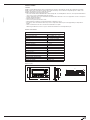
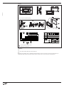
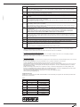
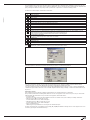
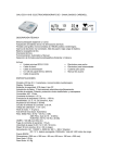
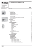
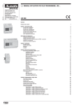
GB USER’S MANUAL OF HMI - HUMAN MACHINE INTERFACE
I323 GB 07 11
LOVATO ELECTRIC S.P.A.
24020 GORLE (BERGAMO) ITALIA
VIA DON E. MAZZA, 12
TEL. 035 4282111
TELEFAX (Nazionale): 035 4282200
TELEFAX (International): +39 035 4282400
E-mail [email protected]
Web
www.LovatoElectric.com
LRX P01
WARNING!
– Carefully read the manual before the installation or use.
– This equipment is to be installed by qualified personnel, complying to current standards, to avoid damages or safety hazards.
– Before any intervention, disconnect all the circuits.
– The manufacturer cannot be held responsible for electrical safety in case of improper use of the equipment.
– Products illustrated herein are subject to alteration and changes without prior notice. Technical data and descriptions in the documentation are
accurate, to the best of our knowledge, but no liabilities for errors, omissions or contingencies arising therefrom are accepted.
– Clean the device with a soft dry cloth; do not use abrasives, liquid detergents or solvents.
CONTENTS
CHAPTER 1: SUMMARY
Function
General specifications
Dimensions
Installation
Components
LCD
Keys
Communication ports
2
2
2
2
3
4
4
4
5
CHAPTER 2: EDITING SOFTWARE LRXSWP01
General instruction
About the project and screen
Flowchart of usage
Editing the user’s screen
Create a new project
Making basic screen
LRXSWP01 configuration
LRXSWP01 properties
Text
Dynamic text
Function keys
Data display
Data setting
LEDs
Function keys to control status switches
Bar graph
Trend line
Alarm list
Chief button
Copy the value of registers from one device to another
Save project
Download window
Import of .OPf format project
5
5
5
5
5
5
6
7
8
8
9
10
11
13
15
15
16
17
17
18
19
20
21
22
CHAPTER 3: SETTING
Communication
Changing the screens
System password
24
24
24
24
CHAPTER 4: CREATE NEW DEVICE
26
CHAPTER 5: COMMUNICATIONS
Accessories
Communication ports
Communication connections
32
32
32
32
1
CHAPTER 1: SUMMARY
I323 GB 07 11
FUNCTION
LRXP01 is a Human-Machine Interface that is used with many types of PLCs or other intelligent controllers with communication ports. With
LRXP01, both the values of the PLC inner registers and the status of PLC relays can be monitored or changed through texts or LEDs. So the
operation of the machines or devices is easier and convenient.
LRXP01 programmable text monitor has many features:
– The screens are made with the LRXSWP01 editor software though a PC. Text, including Chinese characters, can be input and the PLC address
can be set. The screens are downloaded through the serial port.
– The PLC communication protocols are downloaded to the LRXP01 with the data of the screens so the programmer or user does not require to
program communication features.
– Supports Modbus®-RUT protocol.
– Users can set 6 passwords, which have 3 levels.
– Alarm list function is available; the current alarm information is displayed one by one.
– It has 24 keys, which can be defined as function keys. There is a keyboard for numeric input. Use and programming are simple and user
friendly.
– Various communication modes can be selected. RS232 and RS485 are acceptable.
LRXP01 supports different screens in one project communication with other devices through different ports.
GENERAL SPECIFICATIONS
POWER SUPPLY
Rated input power supply
24VDC
Input power voltage range
20.4…26.4VDC (-15%...+10%)
Power consumption
1.9W
Wire size
0.4…3.3mm² (22-12 AWG)
Tightening torque
1.8Nm / 10.4lbin
AMBIENT CONDITIONS
Operating temperature
0…+55°C
Storage temperature
-40…+70°C
Altitude
≤2000m
Relative humidity
10…95% (non-condensing)
Maximum pollution degree
2 (IEC/EN 61131-3)
Vibration resistance
15g
Shock resistance
0.5g
Weight
200g
CERTIFICATIONS AND COMPLIANCE
Certifications obtained
cULus
Comply with standards
IEC/EN 61131-2
Dimensions [mm]
Front and side view
Top view
85.5
101.5
163.5
5.5
179.5
2
33
Installation
Mounting in enclosure
Cut-out
>50
165
87
➊
>50
>70
>50
I323 GB 07 11
>50
R2
Mounting surface
Fixing clip elements (standard-supplied)
Wiring
COM1
RS485
+24V
O
A
B
SG
mm
2
AWG
0.4~3.3
22~12
C
24VDC
Nm
1.8
lb-in
10.4
A
A
1A fast acting fuse, automatic circuit
breaker and circuit protection.
COMPONENTS
LCD
4.3in., monochromic display, 192x64 pixel, olivine background.
KEYS
On the front panel of LRXP01, there is a LCD display and 24 thin membrane switches. The keys have a smooth touch feeling and they are
endurable and reliable. Besides being used for the basic functions, all 24 keys can be set for local functions or Chief functions.
3
The basic functions of the keys are:
Basic function
[ALM]
When pressed, the LRXP01 shifts to the predefined alarm list information screen. It can also be defined as a specific function key.
If there is no alarm list in the project, system function is ineffective.
▲
When pressed, the LRXP01 returns to system initial screen. The user can designate the system initial screen during the screen
setup procedure (default value is screen no.1; screen no.0 is prohibited). Usually the main menu screen or the most-frequentlyused screen is set to be the initial screen.
[ ]
Left shifting of the digit being edited when changing the register data. When pressed, the flashing digit will be shifted to the left.
▲
I323 GB 07 11
KEY
[ESC]
[ ]
Right shifting of the digit being edited when changing the register data. When pressed, the flashing digit will be shifted
to the right.
[▲]
Jump to the previous screen. The number of the previous screen is designed in the Screen Attribute option (default value is the
result of substracting 1 from the current screen number).
In data setting mode, pressing it can add 1 to the digit being edited. The value will increase from 0 to 9, then return to 0….. (DEC);
increase from 0 to F, then return to 0….(HEX).
[▼]
Jump to the previous screen. The number of the previous screen is designed in the Screen Attribute option (default value is the
result of adding 1 from the current screen number).
In data setting mode, pressing it can substract 1 from the digit being edited. The value will decrease from 9 to 0, then return to 9…
.. (DEC); decrease from F to 0, then return to F.(HEX).
[SET]
Press it to enter the mode for editing the value of registers. The register being operated is displayed in reverse colour. The digit
being edited flashes.
If the current screen contains no register setting components, no operation will be executed. When [SET] is repressed before
[ENT], the edition made to the current register will be cancelled. The user can continue to operate with the next data register.
NOTE: The function of register setting for [SET] CANNOT be disabled by the user-defined function.
[ENT]
When password protection is enabled, pressing it will pop up a screen for password setting.
In register setting mode, pressing it means the edition on the current register is finished. The edited data will be saved. Then, the
edition will move to the next register. After the edition on the last register on the current screen has been finished, it will quit from
the register setting mode.
[CLR]
When pressed during the process of data input, current data can be cleared.
[+/–]
When numbers are inputted with symbol, pressing it can change the symbol.
0-9
F1-F4
1. They can be used as button controller, setting status of the coils, screen jumping or editing the values of the registers.
2. When users in editing mode of the value of registers, the keys can input values directly.
Chief control keys. These basic function is switching screens, changing the status of the coils and I/O, editing the values of the
registers, etc.
The high-level function is controlling the destination machine to be powered on or off, etc.
– Keys which are user-defined for local-button function
All of the 24 keys can be defined for specific functions by users; for example, setting the status of the coils, screen jumping, setting the
registers, increasing by degrees, descending, etc.
Local buttons can be set in the current screen. It is effective only when the current screen is displayed.
– Keys which are user-defined for Chief-button function
All of the 24 keys can be defined for specifc functions by users; for example, setting the status of the coils, screen jumping, setting the
registers, increasing by degrees, descending, etc.
Chief buttons can be set under the tool menu. It is effective whatever screen is displayed.
– The priority of the functions
When a key is user-defined for a specific function, it has many functions. But only the function, which has the highest priority, can be executed.
Other functions are ignored.
Except for the [SET] and [ALM] keys, the priority from high to low is: local button→Chief button →basic function.
For [SET] and [ALM] keys, the priority from high to low is basic function→local button→Chief button.
The basic function of register setting for [SET] has the highest priority. So if there is a function of setting register in the current screen do not
define [SET] for other functions. Pressing [SET], after enteroming the setting function, all of the user-defined key function are not effective
until setting function is ended.
[ALM] key has the highest priority when there is an alarm list. So if there is a function of adding alarm list, do not define [ALM] for other
functions. Pressing [ALM] key after entering the alarm list, the user-defined local buttons are ineffective. [▲], [▼], [ESC] keys return to their
basic functions. Others hold the Chief button functions which have been defined before.
LRXP01 display has LED backlight itself. As long as there is a key usage, the backlight will remain on.
Users can also set the backlight always on.
COMMUNICATION PORTS
LRXP01 has two communication ports: COM1 and RS485. COM1 is used for downloading user programs, and offers RS232 port. RS485 offers
RS485 interface for networking.
COM 1:
PIN
Definition
Details
1
-
Reserved
232 receive signal
2
RX
3
TX
232 send signal
4
NC
Interior use, cannot
be connected to GND
5
GND
0 LEVEL
6
-
Reserved
7
VCC
5V high level
8
-
Reserved
9
-
Reserved
RS485:
A
4
B SG
CHAPTER 2. EDITING SOFTWARE LRXSWP01
GENERAL INTRODUCTION
LRXSWP01 is the specific configuration software for the programmable text monitor LRXP01. It can run on Windows 98/2000/XP/VISTA
platforms. It is easy to study and convenient to use. The user can directly input English / Chinese characters.
I323 GB 07 11
ABOUT THE PROJECT AND SCREEN
The basic element of a project is the screen. All the screens for one certain project are saved in a single project file. Every screen is made to
execute some certain functions. By arranging the screens, the user can jump from one screen to another. The application project file is composed
of all the screens.
CONTENTS OF THE SCREEN
After opening a project, users can create (“new”) or open (“open”) a screen. The user can put some elements, such as characters (English or
Chinese), LEDs, switches, data inputting boxes and jump keys on every screen. Jumping between different screens is allowed. The operator can
carry out operations, such as data monitoring, parameter setting, switch controlling, alarm list monitoring and data transferring between registers
of PLCs.
FLOWCHART
The basic flowchart of use is shown in the following figure:
Software
installation
Run the
software
Create or
Open a
project
Create or
Open a
screen
Edit the
screen
Save the
project
Read LRXP01
Run
Download
the screens
EDITING THE USER’S SCREEN
CREATE A NEW PROJECT
Run the software LRXSWP01 and create a project, after which a screen editor will be shown on the screen.
5
The screen-editing region is in the centre of the editor. There is a grid of white dots in the display region. The distance between every two rows
and two columns is 16 points. The whole region is a matrix of 192x64 points. The user can refer to the dots nearby to align the components when
laying or moving them. When necessary, change X and Y positions of the components to locate them in arbitrary positions.
The table below is the description of all the buttons in the toolbar:
Button
Functions
Create a new project.
I323 GB 07 11
Open the project.
Save the project.
Dowload the configuration project to LRXP01.
Upload the project inside LRXP01.
Translate and edit the project; show the information of the project.
New screen. Pressing the key “New”, the screen indicator will also display a new screen.
Edit the attribute of the screen.
Change a screen with the copy of another one.
Delete the current screen.
Designate the initial screen. When the display is running, the system will return to the initial screen directly if [ESC] is pressed.
Usually the main menu or the screen most-frequently used is set to be the initial screen.
Set the system password and the definition number of the ineractive controlling register.
Login the Alarm List information.
Every piece of information represents a status of the select variable.
Set Chief button.
Change the data of the registers with the copy of another device.
Preset dynamic test.
Preset register.
Press
or activate [File] →[New] command in the menu to pop up a dialog box for PLC selection.
Select the proper device. Then click “Set” button down beside the port name to set communication parameter:
Select the proper baud rate, data bits, stop bits, parity and communication port in the dialog box. LRXP01 supports the function that two
communication ports can connect with different PLCs and traducers using different communication formats.
Select the proper PLC type based on the destination controller. When LRXSWP01 downloads (writes) the screens, it sends the appointed PLC
communication protocol and the data of the screens to LRXP01 altogether. When the display is running, it communicates with the PLC through
the protocol.
MAKING BASIC SCREEN
In the example give below, the PLC type is LRD. The example will give you a general description of screen making.
Firstly, enter the system initial screen editing mode; default screen is no.1. The properties of the current screen (screen no.1) are shown at the
right and bottom edge of the interface. Every screen has its own properties, which include 4 items:
– Screen description
Describe the use of the screen. It helps the programmer to note the use of all the screens (can be omitted). For example: “main menu”.
– When Up arrow key [▲] is pressed, jump to screen.
Insert the number of the screen to which it will jump to.
– When Down arrow key è [▼] is pressed, jump to screen.
Insert the number of the screen to which it will jump to.
– Choose communication port:
LRXP01 supports every individual screen choosing its own communication ports.
The most convenient way for screen jumping is to press [ESC], [▲], and [▼] when LRXP01 is running. The user can also jump from one screen
to another by pressing the user-defined function keys.
6
I323 GB 07 11
NOTE:
– It the [▲] and [▼] keys in the current screen are defined for other functions, the screen jumping parameters of the screen properties are
invalid.
– If the screen designated by the [▲] key does not exist, the system will search up until the existing screen is found and jump to it. It will stop at
screen no.1 if no screen is found. The situation of the [▼] key is similar; this means the system will search down for the screen if the
designated one does not exist.
– If there are some data setting components in the screen, [▲] and [▼] keys will execute the function of value increase and decrease in the data
setting mode. After quitting the data setting mode, the [▲] and [▼] keys will execute the basic function for screen jumping.
– Choose the communication port of the screen. Users can choose COM1/485 port as the communication port of the current screen. Users also
can set the COM1/485 communication port of LRXP01 to demand the data of different destination host at the same time.
For example: Screen 1 can be set as communicating through 232; Screen 2 can be set as communicating through 485. They are separate.
CONFIGURATION OF LRXP01
Press
or activate [Tools]→[LRXP01 serial Set] command to pop up a dialog box for configuring the system parameters of LRXP01.
– Initial Screen
The first screen will be displayed after power on. Usually this screen is set to be the main menu screen or the most-frequently-used screen.
Press [ESC] when the LRXP01 is running, the system will jump to this screen directly.
– Screen Saver
Under default conditions, the backlight is set at “None”. This time can be set by the user. If it is set at “None”, the backlight will always remain
on. Also, the screen can be set to jump to a
screen saver when no key is pressed in configurable time.
NOTE: If the screen has jumped to a screen saver screen, the pressing of any key will not carry out any function. Any operation will awake the
screen saver to return to the original screen.
– LRXP01 Serial Status Control
Usually the screen changing is executed by pressing the keys. Besides, the PLC can change screen by changing the data in register. If this
property is selected, the number “n” will be written into the LRD, for example, controlling register at the beginning of running, then LRXP01
will jump to screen no. “n”. LRXP01 writes the current screen number into D301, so the PLC can know the status of LRXP01; users
can choose the function to clear the register in the screen. After jumping to that screen, the data in controlling register will be cleared.
NOTE: The user can define the address of the interactive controlling register.
– Encrypt the project
Users can upload the project from LRXP01 to the PC and edit it. If users require the configuration screens in the production cannot be
uploaded illegally, they can choose this option. After choosing this option, the data cannot be uploaded even though someone has the highest
level password in the project.
– Communication time
Communication time is the interval between LRXP01 sends two communication commands. Its value can be set between 10ms and 100ms. If
the corresponding controller answers fast, the communication time can be reduced, On the contrary, the time will increase, Under the default
conditions, LRXP01 sends communication data every 20ms.
– Overtime
The time decides when LRXP01 demanding data overflows. Some controllers read data fast, but take a long time to write data. In this
condition, users can set the longest write time as overtime to avoid data setting errors when increased data of register is by degrees.
7
PROPERTIES OF LRXP01
Component
Function
Input text, including Chinese characters and English letters.
Dynamic test list. The content of the text can be changed dunder the control of PLC register.
Register components. The user can dispose some data setting monitoring components with it.
The related addresses are the PLC registers.
LED indicator. Indicate the on/off status of the inner delays in PLC.
I323 GB 07 11
Function key. All 24 keys can be defined to be function keys. They can execute the functions such as screen jumping and
switch control.
Bar graph. Monitor the data change in PLC in the form of bar graphs.
Trend line. Monitor the data change in PLC in the form of trend lines.
Paste photograph. Paste a monchrome BMP format photo (max.196x64 pixels) on the screen
Alarm list. Users can set 8 groups of alarm lists corresponding to 8 different hosts at most. There are at most 32 pieces of
alarm information in each group.
TEXT
The example below shows hop to design a main menu screen as the screen no.1.
Firstly, lay the text “Main Menu”. Press and click the left button on the editing region to confirm the operation (right click will cancel it). After left
click, the default text “TEST” will be displayed in the editing region. The properties of the test are displayed below the editing region. The text
string will move as the user moves the cursor. To locate the text in an arbitrary position, edit the X and Y coordinates. Changing the content of the
text to LRXP01, the corresponding text string will be displayed in the editing region.
– Coordinates
X value represents the horizontal position of the text string.
Y value represents the vertical position of the text string.
The origin of the position is the upper left corner of the screen.
– Speciality
Double: The text will be displayed in double size, both horizontally and vertically.
Reverse: The text and the background will be displayed in reverse colour.
– Text
The content that will be actually displayed is input here. The user can input English letters or Chinese characters with various types of Chinese
input methods in this textbox. The content in it can be copied or pasted.
8
I323 GB 07 11
DYNAMIC TEXT
Press
and click the left button on the editing region to confirm the operation (right click will cancel it). After left click, the default text
“DYNAMIC TEXT” will be displayed on the editing region. The properties of the dynamic text are displayed below the editing region. The text string
will move as the user moves the cursor. To locate the dynamic text in an arbitrary position, edit the X and Y coordinates.
– Coordinates
X value represents the horizontal position of the text.
Y value represents the vertical position of the text.
The origin of the position is the upper left corner of the screen.
– Speciality
Double: The text will be displayed in double size, both horizontally and vertically.
Reverse: The text and the background will be displayed in reverse colour.
– Coil
The PLC data register for controlling the status change of the dynamic text.
– Mode
Determine the data form of the data register. The form will affect the display form of the numeric items in the dynamic text.
– Type
Users can choose “Bit Element” or “Word Element”.
When users choose bit element, dynamic text relates with the status of the select variable inside the PLC. The corresponding text can be set to
0 or 1, two types of status.
The figure below shows bit text:
When M0 is 0, the dynamic text shows “M0=0”. By contraries, it shows “M0=1”.
If the dynamic text corresponds to Word Element, it can keep the texts corresponding to as many as 32 different statuses.
– Display Text
Log the different text content corresponding to different values of the data register. It can keep the texts corresponding to as many as 32
different statuses. The value of the text can be inconsecutive. Users can input the value themselves.
Example: Display the dynamic text controlled by register D10. The dynamic text to be displayed has three statuses: “In gear”, “Temp. Lower”
and “Position arrived”. The three texts correspond to the D10 register value 2a, 30e and d43f (HEX form) respectively. Input “2a” in the
“Value” space of the first row and “In gear” in the “Context” space on the right.
Input the other two statuses in the same way. If the value of register D10 is 2a, the dynamic text displayed is “In gear”. If it is 30e,
“Temp. Lower” is displayed. Other conditions can be inferred from the two examples above. The example is shown in the figure below:
9
▲
FUNCTION KEYS
Next, configure the function keys in the main menu screen to execute the function of screen jumping (for example, press [ ] to jump to the
parameter setting screen; press [ ] to jump to the mode setting screen). The procedure of defining the function keys is:
▲
I323 GB 07 11
▲
Press
to activate a dotted rectangular box. The box moves as the cursor moves. Click the left button to determine the position of the function
key. A hand shape and the function key to be defined (default key is [ ]) are displayed in the editing region. The properties of the function key are
displayed below the editing region. The meanings of position and style are the same as those in the text property. They indicate the position, the
size and the colour of the graph.
The function key setting screen is shown in the figure below:
– Key
Select a proper key among the 24 available. Do not conflict with system keys.
– Hand
For the convenience of use, add a hand shape symbol before the key symbol. The hand indicates that pressing the key will carry out an
operation. The user can remove the hand shape to save space.
– Hide
The user can make the symbols of some keys invisible in the screen. But the function of those keys is still valid.
– Encrypt
Only when the system password is entered correctly, the function key can execute its function.
– Coil
The function key is defined to set a switch.
– Screen
The key is defined to execute the screen jumping function.
– Register
The key is defined to set the register parameters.
– Increase
The value of the destination register will increase an appointed constant in the user-defined range
– Degression
The value of the destination register will decrease an appointed constant in the user-defined range.
– ID
The station number of the PLC.
– Type
When the key is defined to set a switch, the definition number of the PLC relay corresponding to the switch is determined by the type here.
– Group name and Element name
Set the address of the relay.
– Set ON
Set the designated relay on.
– Set OFF
Set the designated relay off.
– Reverse
Set the designated relay to be of negative logic.
– Instantaneous on
The designated relay will be set on when the key is pressed down. When the key is released, the relay will be set off.
– Instantaneous off
The designated relay will be set off when the key is pressed down. When the key is released, the relay will be set on.
10
I323 GB 07 11
Click the down arrow on the right of the list to show the names of the 24 keys. Select the proper key to be defined.
▲
To make the screen simple, the hand shape can be removed by not selecting the checkbox “Hand”. In this way, only the keys are known on the
screen. Select the option button “Jump to” to define the key as a screen jumping function key. Designate the target screen number below the key.
If the number is 10, it means screen no.10 is the parameter setting screen.
To hide the parameter setting screen, select the checkbox “Password” to enable the password property. Thus the system will jump to screen
no.10 only when the password entered has the same or higher priority and it is correct.
After setting the function key, put the text “set parameter” beside the key symbol to inform the operator that it will jump to the screen for
parameter setting when [ ] is pressed.
NOTE: To leave some margin for inserting new screens, the number of different types of screen should not be continuous.
Setting register parameter with a single function key
To write a parameter (or constant) to be designated register, select a function key from the key list and select the option button “Register”. The
constant parameter will be written to the designated register when the key is pressed during running. Setting as the following figure will write the
hexadecimal number 7FFF to the D register at address 0.
Increasing the constant of the register with a single function key
To increase a parameter (or constant) to a designated register, select a function key from the key list and select the operation button “Increase”.
The constant parameter will increase by degrees until the upper limit value is reached.
The example below can let the register D0 add 100 every time the key is pressed, the upper limit value is FFFF (Hex).
Degression
It is similar to the above. Users should set the lower limit value. Under the default conditions, the Min limit value is 0.
DATA DISPLAY
This section introduces how to make a Set parameter screen. The methods of setting the components, such as parameter display, parameter
setting and password setting are detailed below.
The procedure of making the screen
Click [Tool] → [New Screen] or click the screen description to pop up a dialog box for setting the screen number and relative description.
11
– Screen Num:
The serial number of the new screen.
– Screen Description
Describe the character of the new screen.
I323 GB 07 11
Click the blank of the screen editing region or click the screen description in the left of the dialog box to pop up “Screen Property” dialog box of
the current screen.
– Up” / “Down” key to screen
Choose the screen to which jump when the [ ▼] / [ ▲] key is pressed.
– Option
Choose the communication port of the current screen. LRXP01 supports different screens in one project communicating with other devices
through different ports.
Open the data display boxes. Press
to show a rectangular dotted box moving with the cursor. Click the left button in the proper position. The
number “12345” in the dotted box indicates that this component is a five-digit register display / setting box.
The properties of the dialog box are:
– ID
The definition number of the PLC register corresponding to the display component.
– Register num
It is the amount of the registers being display or set. The minimum number is 1 and the maximum is 2.
– Encrypt
If selected, the data can be changed only when the correct system password is entered. The command for setting the password is in the menu
“Tools(T)”.
– Show
Input Digit
The maximum number of digits of the data being displayed or set.
Point Digit
The length of the significant digits after the decimal point.
– Indent Manner
Right indent: When users only want to show the high bit.
Left Indent: When users only want to show the low bit.
Example: The presettable value of T register of LRD is from 0 to 99999.
Users can chose 4 bits to display, left indent, ignores high bits. Now the value is from 0 to 9999.
– Decimalist
The data in the register will be displayed in decimal form.
– Signed
Only valid when the “Dec.” mode is selected. If the highest digit of the register is 1, the data will be displayed as a negative number.
Example: The hexadecimal number FFFEH is represented by -2.
– HEX/BCD
The data is displayed in hexadecimal form.
– Set
The component can be used for setting data if it is selected. So the component can be used for both monitoring and setting the data.
The register set box has some special properties: maximum, minimum and password.
– Project data
Project data shows proportional data.
12
I323 GB 07 11
Example 1:
Set A output as below:
Group name= D; Element name= D0; Register Num= 1; Input Digit= 5; Point Digit= 0; Decimalist; does not show the negative.
Use the same method to set the current screen, which shows the output of B. The register address is D1. Other properties are the same as A.
After downloading the configuration screens from PC to LRXP01, LRXP01 will demand the value of D0 and D1. Then the value will be displayed
on the screen in time. Users only need to put the output of A in D0, B in D1. They do not need to care about the communication.
The Converted Data= (original register data – Min Input) * (Eng. Max – Eng. Min) / (Max Input – Min Input).
DATA SETTING
Continue the configuration of the parameter-setting window. Press
to show a dotted box moving with the cursor. Move the cursor until the
proper position is reached, then click the left button to confirm the position. Select the “Set” checkbox. In this way, the component has the
function of monitoring and setting the data.
If the “Set” checkbox is selected, two additional options, “Encrypt” and “Upper/Lower Limit” are enabled.
13
I323 GB 07 11
– Encrypt
To enhance the security of the device, the operation of parameter setting can be protected by password.
To set or change the password, activate the command “Tool(T)”→ “Password level set” to pop up a dialog for password setting:
Enter a new password, change the original password or set the priorities of the passwords.
For example, enter “5678”, choose the priority “Mid-Level” and click “OK”. Then the password is confirmed.
There are at most 6 passwords which can be set in LRXP01. Those passwords are classified into 3 ranks. “High-level” has the highest priority
while “Low-Level” has the lowest.
For example, if one specific key needs a “Mid-Level” password to react, now inputting “Low-Level” password is useless.
You can input “Mid-Level” or “High-Level” password to run this function.
When the operator presses the key [ENT], the LRXP01 will pop up a password enter window. Appointed data can be changed only when the
priority of the entered password is the same as or higher than the one of the registers.
The password is effective only once. Users need to input the password again, when they want to modify the data a second time.
– Limit Set
The programmer can set limits to the data to make the data out of limits invalid. Thus the possible damage done by inputting data too great or
too small is avoided. For example, let the maximum input be 9000 and the minimum be 0. The setting value will be written in the maximum
into the register only when it is between 0 and 9000, or the system will halt until a correct value is entered.
– Original and Project data
After selecting the “Limit Set” checkbox, the programmer can select the original data or the project data from the list.
Original data
The original data option means that the data in the register will be displayed without any operation. The position of the decimal point is
determined by the value of the “Decimal” property. For example, if “Decimal”=2 and the register value is 14561, it will be displayed as 14561.
Project data
This option means that the data read from the register will be converted to project data before being displayed. The conversion is done
following the formula below:
Converted Data= (original register data – Min Input) * (Eng. Max – Eng. Min) / (Max Input – Min Input)
Users can use project data in such conditions, for example:
AD relay input is 0-102.3. But users want to show the data as 0-10V.
Calculate the new data which according to the input of project data. Then modify the value of corresponding register inside the PLC to the new
data. Etc.
Example: Users should set 0-10V to correspond with the AD inputting register D0(0-1023).
Set as below:
When user set 10, the value of D0 is 1023.
When user set 0, the value of D0 is 0.
The value of D0 is (original register data – Min Input) * (Eng. Max – Eng. Min) / (Max Input- Min Input).
14
I323 GB 07 11
LEDs
Create a new screen like this:
Press
to put a LED. There is a dotted box which moves with the cursor in the editing region.
Click the left button in the proper position to locate the LED.
– Coil
The definition of the PLC intermediate relay that corresponds to the LED.
– Shape
The shape of the LED, round and square.
– Positive Logic
The LED is filled when the corresponding intermediate relay is ON. It is unfilled when the corresponding intermediate relay is OFF.
– Negative Logic
The LED is unfilled when the corresponding relay is ON. It is filled when OFF.
FUNCTION KEYS (for controlling the status switches)
▲
▲
Press
to activate a dotted rectangular box. The box moves as the cursor moves. Click the left button to determine the position of the function
key.
Select button [ ] . Set the attribute as below:
It means the status of coil M0 is reverse when [ ] is pressed.
15
BAR GRAPH
The bar graph can give a direct view of some analog parameters such as flow rate, pressure and level. The user can set the height, width and the
direct of it arbitrarily.
I323 GB 07 11
Press
to show a dotted box that moves with the cursor. Move the cursor to the proper position and click the left button to locate the bar
graph there.
– Register
The address of the register corresponding to the bar graph.
– Full Value
The register value corresponding to the full bar graph.
– Zero Value
The register value corresponding to the empty bar graph.
– Direction
The direction of the bar graph, including four options: up, down, left and right.
– Size
The height and width of the bar graph.
The next example shows how to use the bar graph to show the pressure.
The bar graph demands the data in D0. When the bar is full, it means the data is 1000 in D0. When the bar shows the scale of 500, it means the
data is 500 in D0.
Bar graph shows data directly and it is real-time updating. It is suitable for showing pressure, voltage or other signals like these.
16
TREND LINE
Some parameters in industrial control applications vary at a slow rated. Often, the operators want to know the variations of these parameters in a
certain time. Trend line is the choice.
I323 GB 07 11
Press
to show a dotted box that moves with the cursor. Move the cursor to the proper position and click the left button to locate the trend
line there.
– Register
The address of the register corresponding to the trend line.
– Full Value
The register value when the trend line reaches the 100% of the scale.
– Zero Value
The register value when the trend line reaches the 0% of the scale.
– Data Collection (number of dots)
The total of the sample points in the whole trend line. The more sample dots the trend line has, the more details it can provide. Certainly more
sample dots make the time period longer. The largest number of the dots is the width of the trend line minus 2.
– Time Interval
The interval between two sample points. Max 65535 seconds, min: 1 second.
– Size
The length and width of the trend line. Max: 192x64 point; Min: 16x16 point.
NOTE:
1. A trend line component can display only one line.
2. There is no limit to the amount of the trend lines on the screen. But the amount of data collection cannot be more than 384 on one screen.
3. The newest data is shown on the right side of the trend line. When a new data comes in, the other former data moves to the next left grid.
ALARM LIST
In industrial auto-control applications, alarming is a very important function. It can be used in many cases. Alarm list is the most direct and
simple method.
Every project of LRXP01 can have a cluster of alarm list information. Every piece of information corresponds to a relay. The addresses of all the
relays are continuous. The user can designate the initial address of the relays. When any of the relays jump from OFF to ON. The corresponding
alarm information is activated. LRXP01 will pop up the alarm window, where the alarm information is displayed in the first row. If another relay
jumps to ON, the new information will be displayed in the second row. When an alarm relay jumps to OFF, the corresponding alarm information
will disappear automatically.
To log alarm information, press
to pop up the alarm list dialog box:
17
I323 GB 07 11
The list is blank when no information has been logged. Move the cursor to the “Alarm content” column and enter the information “Temp.
Too high”. Press “Enter” to show the screen as follows:
Input other information in the same way:
After entering all the information, set the coil type and address to M0 (for example) to indicate that the relays M0-M2 correspond to three pieces
of alarm information.
When LRXP01 is in gear, if M0 and M1 are set ON, it will pop up an alarm window and display as the figure shows below:
Seeing this alarm window, the operator can take some measures to solve the breakdowns. Press [ESC] to return to the monitoring window. When
LRXP01 displays a common screen, users can press [ALM], if they need to inquire about the status of the alarm infirmation of current destination
controllers. Then the system will jump to the alarm screen.
CHIEF BUTTON
Click
in the toolbar to pop up a Chief Button dialog box.
Click [New] to add “←” button. Set the function as “M0 – SET ON”.
18
I323 GB 07 11
The button of LRXP01 can be set for chief function. The priority order from high to low is: basic function > local button > Chief button. So if there
is a [←] on the screen, LRXP01 will execute the function which is on the current screen when the button is pressed.
COPY THE VALUE OF REGISTERS FROM ONE DEVICE TO ANOTHER
Click
in the toolbar to pop up a Copy Register dialog box.
Users can set 3 groups of relationships for register transfer. During every communication scanning cycle, LRXP01 will check the synchronisation
between source PLC and those of destination PLC once. If source PLC has communication errors, LRXP01 will not update the registers of
destination PLC. Every corresponding relationship contains one group of Source address, 5 groups of destination addresses and can transfer 16
seriate word registers (double word register transfer are not supported) at most.
Click “New” button. An “Add Register” dialog box will pop up. Set the attribute of the register:
Example of copy the content from D0-D10 of ID1 to D20-D30 of ID2
19
I323 GB 07 11
It does not matter that source PLC and destination PLC are not on the same bus. LRXP01 can use download port to communicate with source
PLC, then send the data of registers to the destination PLC through 485 bus. Users only need to simply choose the communication port in the
dialog box.
PRESET DYNAMIC TEXT
Set the relationship between the status of M01 and the dynamic text:
SAVE PROJECT
Press
or click [File] → [Save] to show the save dialog box as follows:
Select the proper path and filename to save the file. The system defines “opf” as the default external filename.
Enter the filename and select the proper path, then click “SAVE”.
20
I323 GB 07 11
DOWNLOAD WINDOW
Connect the 9-pin RS232 serial port of PC and that of LRXP01 with the communicable cable, e.g. LRXC02.
Make sure that LRXP01 is connected with a 24VDC power supply.
Click “File(F)”→ “Port” to set communication attribute:
Such dialog box pops up:
This dialog box is used to set the communication port for downloading configuration screen. Users should set the attribute of serial port carefully.
Choose “Option(O)”→”write” or press
to begin the download process.
Each screen has a certain character space to describe its own function. Users can choose whether these characters download to the memory of
LRXP01. Next time, these characters can be displayed when the project is uploading.
If “NO(N)” is chosen, LRXP01 will not display these characters.
A dialog box will be displayed to indicate the progress of downloading:
If LRXP01 successfully downloads all the screens, this dialog box is viewed:
21
I323 GB 07 11
If LRXP01 fails to download the screens, this other dialog box is viewed displayed.
When a communication error is displayed, check the power supply, whether the download cable is connected in the right way and whether the
users have chosen the proper COM port.
IMPORTING .OPF PROJECT
Users can read the data of a project on LRXP01. The precondition is that the project is not encrypted (the “Encrypt Project” option has not been
chosen; press
Encrypt:
seen in the dialog box).
When this option has been chosen, the data is protected. Users cannot use LRXSWP01 to read the project.
The flow of project reading is as follows:
Press “File”→”Port”
Choose the proper PC serial port.
Click
22
in the toolbar or choose “Option” → “Read”:
I323 GB 07 11
Reading:
Reading successful:
Just as the figure shows, after the successful ready of the project, users can go on to edit it.
The condition aforesaid is that users have not set a password (level) yet.
If users had already set a password (level) like this:
Click in the toolbar or choose “Option” → “Read”. This dialog box will be displayed on the PC screen:
Input the high-level password of the project ---“6666” to go to the next setp. If there are more than one high-level passward, inputting anyone of
them is suitable.
23
CHAPTER 3 – SETTINGS
COMMUNICATIONS
Connect LRXP10 and PLC with a communication cable. (Pay attention to 2 ways of connection:
RS232 and RS485).
Turn on the power supply for both LRXP10 and PLC. If communications are in gear, LRXP10 can carry out the operations such as data
monitoring. If there are communication-parameter errors or connection-cable errors, the communication will fail. The type of error will be
displayed in a flashing manner in the middle of the display. It shows the condition of communications.
I323 GB 07 11
CHANGING THE SCREENS
Consult other examples.
SYSTEM PASSWORD
Read the data of the project by using password: If there are passwords in the project and there are no options to encrypt the system, users can
upload the project to a PC and use the software to edit it again. Users must input the high-level ‘password to read the data when a dialog box
which inquires about inputting password pops up during reading.
▲
Example 1: Encrypt the key when the key controls register.
Put [ ] button in the editing region. Set the function as: Change the value of D0 into 1234. Users must set password (level) first to use the
“Encrypt” function. Now if you choose “Encrypt” box, a warning dialog box will pop up if the system has not been set up with password.
24
I323 GB 07 11
Choose “Tool”→”Encryption level set” to pop up dialog box. Set 6 passwords.
▲
Return to the screen to set the key level. Choose “Mid-Level”:
After configuring the function correctly, users need to input password when [ ] button is pressed.
Because the Key Level has been set as “Mid-Level”, when users input low-level password, they cannot carry out the function to set the register.
Only Mid-Level or High-Level password input will permit to set the value of D0 1234.
Example 2: Encrypt when set the value of registers
25
Users correspond the widget with D0, choose “Set” and “Encrypt” option. Set “Key-Level” as “High-Level”.
Users need to input the password when the press [SET] button. Users will not have the right to modify the data, unless the password they have
just input has the high level. Any of the high-level passwords are acceptable. Then the password is valid for one time only. The next time to modify
data again the user needs to input the password again.
I323 GB 07 11
Remind of setting password: LRXP01 has different levels of passwords. The password is effective just once. So if in one screen there are more
than one widgets used for inputting and all of these widgets can be used with password input, the user can leave the screen hidden. Set a certain
button (Pressing this button makes the display jump to the hidden screen) with high-level password. Make sure that only a system controller can
interview this screen.
CHAPTER 4: CREATE NEW DEVICE
LRXP01 supports that users can add new devices based on the existing communication protocol, such as adding a new PLC device which
sustains Modbus®-RTU protocol.
Click
in the toolbar to create a new project. “New and Select Device” dialog box will pop up.
Click “New Device”:
– Protocol Select: There is a Modbus Slave protocol inside LRXP01. Based on the protocol, users can define address lists of communication
buffer (of destination controller).
– The size of communication buffer: The maximal limit of communication buffer.
– Display Format of 32Bit-Register: In the communication command, it establishes whether the destination controller displays the low word in
the front or not.
– Device Name: Set the name of new devices. The names will appear in the device list. Users can choose the new device accordingly.
26
I323 GB 07 11
Set communication protocol, the size of the buffer, display format of 32Bit-Register and the device name. Users can edit the address list after
clicking “OK”.
Choose “Edit”→”New element Group”:
–
–
–
–
Element Group Name: The name of the new group. For example, there are registers called X, Y, M, T, etc., in LRD.
Element Property: There are 3 types of elements to choose from: Bit element, Word element and Dword element.
Communication command of read and write coil: It can or cannot be activated.
Interval of 32Bit-Register: Users can define the interval of 32Bit-Register themselves.
27
I323 GB 07 11
Set the Element Group Name as “M”. Leave other attributes at default by clicking “OK”.
Choose “Edit” now, some options are changed.
–
–
–
–
28
New Element Group: Repeat previous work.
Delete Element Group: Delete the group which has been selected.
New Element: Create a new element in the selected group.
Delete Element: Delete a new element in the selected group.
I323 GB 07 11
CREATE A NEW ELEMENT
Click “New Element”:
– Element Group Set: Select the group of new elements.
– New Manner: Add a single element or create elements as a batch.
– Element set:
1. Element: Add the name of the element.
2. (Start) Address: Primal address of creating elements as a batch.
3. Position: Primal address.
Add a single element:
Clicking “OK”, there will be a new coil called M= in the group M. Its address is 0.
29
I323 GB 07 11
Creating element as a batch:
Choose “Batch New Set”; the dialog box shows.
– Element Number Type: Set the type of element number as OCT, DEC or HEX.
For example: The X, Y elements of LRD are octal but the D, T, C elements are decimal.
– Address Interval (Increase): Set interval of two consecutive elements.
– New Element Amount: Total of new elements.
– Start Element Name Number: Set Start Element Name Number.
Set M1 as the primal element. The amount of new elements is 9. Its address is 1. Other attributes are default. Click “OK”; the elements in the M
group are show as below:
According to the dialog box, the result of creating elements as a batch is the same as creating a single element. If there is a certain rule of these
elements, we recommend users to create elements as a batch.
DELETE ELEMENTS:
Select M9 in the address list:
30
I323 GB 07 11
Choose “Edit”→ “Delete Element”.
Select “Delete Element” to pop up a confirmation dialog box:
Click “YES(Y). Address list has changed:
M9 has already been cancelled.
31
CHAPTER 5: COMMUNICATIONS
COMMUNICATION PORT
LRXP01 has two communication port: COM1 and RS485; COM1 used for downloading (writing) users’ program. RS485 is used for network
communications using the serial interface.
I323 GB 07 11
1. 9-pin D-shape male plug (COM1)
PIN
DEFINITION
DETAILS
1
-
Reserved
2
RX
232 receive signal
3
TX
232 send signal
4
NC
(This pin connects to the CPU pin inside LRXP01.
Low level: The 232 communication port of LRXP10
is ready to receive configuration data. High level: No use.
5
GND
Ground / Earth
6
-
Reserved
7
RTS
(VCC, gives power supply to LRD program cable)
8
-
Reserved
9
-
Reserved
Pin1
Pin9
2. RS485 serial port
NUM
NAME
1
A-
2
B
3
SG
DESCRIPTION
485 positive signal
485 negative signal
485 GND
COMMUNICATION CONNECTIONS
LRXP01 downloading cable (write configuration screens) – LRXC02
PC
9 pin D-Sub female
LRX P01 Gray
1800
PC Black
Pin
Signal
Signal
RX
2
3
TX
TX
3
2
RX
4
4
GND
5
5
LRX C02
Pin
GND
9 pin D-Sub female
LRX P01
Black
PC
LRX C02
Upload
Download
COM1
RS485
+24V
O
A
B
SG
LRX P01
Gray
32
Connection with LRD relay through LRXP01 RS232 port – LRXC00
-
+
I1
I2
I3
I4
I5
-
+
I6 A1 A2
I1
I2
I3
I4
I5
I6 A1 A2
LRD...
LRD...
I323 GB 07 11
Upload
Download
1
Q1
Q2
Q3
LRX P01
Q4
Q1
Q2
2
COM1
RS485
+24V
O
A
B
SG
LRX C00
Connection with LRD relay in network through RS485 port using LREP00 expansion module
DEL
SEL
ESC
OK
COM1
RS485
+24V
LRX P01
O
A
B
SG
LRD...
LRE P00
RS485
33