1
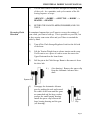
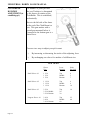
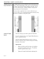
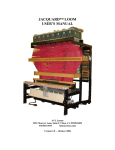
INDUSTRIAL
DOBBY LOOM
User's Manual
AVL Looms
3851 Morrow Lane, Suite 9
Chico, CA 95928-8305 U.S.A.
530 893-4915
530 893-1372 (fax #)
[email protected] (e-mail)
www.avlusa.com
Copyright © 2002
All Rights Reserved Worldwide
TABLE OF CONTENTS
Parts List
INTRODUCTION
About this Manual
PREPARATIONS
Supplemental Loom Support
1.)
Squaring
2.)
Flexible Air Link
3.)
Floor Brackets
SAFETY
TO START THE LOOM
Pre-Op Checklist
Controls
1.)
Computer
2.)
Manual Loom Control
Automatic Loom Control
USING PAUSE, STOP, EMERGENCY STOP
RESTARTING AFTER AN "EMERGENCY STOP"
Reversing Cloth Direction
ADJUSTMENTS
Compressor
FR
REGULATORS
CYLINDER FLOW CONTROLS
SYNCHRONIZED LOOM MOTION
Automatic Cloth Advance Speed Adjustment
Automatic Advance and Cloth Beam Gear Adjustment
Dobby Cylinder Speed Adjustment
Beater Speed Adjustment
Cloth Storage Power Control
CLOTH BEAM ROTATION ADJUSTMENT
Adjusting Lever
Sleeve Exchange
PRESSURE ROLLER
TEMPLE SYSTEM
Setting the Temple Rollers
Temple Rings
WARP TENSION
Set Tension
Troubleshooting Tip
SHUTTLE BOX ADJUSTMENT
Backplate Tilt
Backplate Cant
Shuttle Box to Race Adjustment
Box Timing
1
2
2
3
3
3
3
3
4
5
5
5
5
5
6
7
8
9
10
10
10
11
11
12
12
12
13
13
13
14
15
15
15
16
16
17
17
18
19
19
19
20
20
21
Page i
TABLE OF CONTENTS
MAINTENANCE
Daily
Weekly
Monthly
As Needed
TROUBLE SHOOTING
General
Troubleshooting Tips
Shuttle Doesn't Fire
Shuttle Won't Stay On Race
Shuttle Doesn't Box Completely
Loom Fires On Empty Box
Loom Stops -- Red Light On
Loom Stops -- Green Light On
Harnesses Drop or Don't Lift
Automatic Cloth Advance Inoperable
Inconsistent Pick Count
Loose Shed
Page ii
22
22
22
22
22
23
23
23
23
23
24
24
24
24
24
24
25
25
INDUSTRIAL DOBBY LOOM MANUAL
PARTS LIST
1.)
Harness Pulley Support
2.)
3.)
Harness Pulleys (three sets)
Dobby Cylinder
4.)
6.)
Compu-Dobby
Switch Box
7.)
8.)
Dobby Head
Top Horizontal
9.)
10.)
Four-Box Shuttle Assembly
Beater Top
11.)
12.)
Reed
Shuttle Race
13.)
14.)
Beater Slide Rod
Harnesses
15.)
16.)
Castle
Rear Vertical
18.)
19.)
Beater Cylinder Assembly
Front Vertical
20.)
22.)
Middle Horizontal
Cloth Storage Beam Support
25.)
26.)
Spring Levers
Bottom Horizontal
28.)
29.)
Harness Springs
Beater Slide Bracket
30.)
31.)
Back Plate
Lower Front
32.)
34.)
Spring Lever Support
Harness Cable Retainer
35.)
36.)
Warp Beam Brake Drum
Tension Arm Pulley
37.)
38.)
Warp Beam (plain)
Warp Beam Handle
40.)
41.)
Separation Roller
Warp Beam Retainer
42.)
43.)
Upper Back
Lower Back
Page 1
INDUSTRIAL DOBBY LOOM MANUAL
44.)
Cloth Storage Beam
45.)
46.)
Cloth Beam
Cloth Beam Gear
47.)
51.)
Harness Cables
Beater Slide Bearing
54.)
55.)
Stop Collar
Beater Assembly Mounting Bracket
56.)
57.)
Beater Slide Bracket
Beater Tube
59.)
Rear Beater Shock Absorber Assembly
INTRODUCTION
Your Industrial Dobby Loom (IDL) is designed to be low-maintenance and immediately “user-friendly”. If you are an experienced
power loom weaver, you may initially think this loom is a little
quaint. If you’re more familiar with handlooms, it may seem impossibly busy and complicated. With a little hands-on experience,
however, you’ll find that the IDL is “just right”. Considerable
attention has been paid to the needs of the weaver. In addition to
those things we know you’ll need, we’ve provided features that we
think you’ll want. For example, the cloth beam can be removed so
that you’ll have more working room when sleying the reed and
we’ve placed the main operating controls conveniently “front-andcenter”. Feature for feature, you’ll soon discover that the IDL is
the best loom in its class.
About this Manual
We know that most people have neither the time, nor the interest, in
wading through pages of jargon-laden techarcania. We’ll not
burden you with such here. However, there is certain amount of
information that you will need, like how to turn the IDL “on”, how
to make adjustments, and what you’ll need to do to keep your loom
in top working condition.
Wherever possible, we’ve provided you with “fast-track” explanations through processes. In most cases, more detailed information
will be given in a side bar or information block. And we know that
a picture is worth at least a thousand words, so you’ll have illustrations to guide you as well.
Finally, you’ll find a Maintenance and Troubleshooting section in
the back of the manual.
Page 2
INDUSTRIAL DOBBY LOOM MANUAL
PREPARATIONS
Your IDL will have been assembled and tested before it left the
factory. An AVL technician will, in most cases, have uncrated and
installed the loom at your facility, run it, and made any necessary
adjustments. It is also likely that someone on your staff will have
been oriented to the loom.
Supplemental Loom
Support
Depending on the circumstances of your particular installation, you
may find it necessary to provide some additional support for your
loom.
1.)
Squaring
In order for your loom to function properly, it must be level,
front-to-back and side-to-side. To check front-to-back,
place a carpenter’s level along the top of each Top Horizontal. Check side-to-side by placing the level along the length
of the Cloth Beam and, again, along the Lower Back framing
member. If you find that the loom is significantly out of
level, you’ll need to either correct the floor or shim the legs
of the loom. To square your loom, measure its diagonals,
front to rear. These should be equal.
2.)
Flexible Air Link
If the air line from your compressor is made of a rigid material (steel pipe, pvc, copper), we suggest that you provide a
flexible link between it and the loom. Simply connect a foot
or more of 3/8” air hose between the FR and the end of the
compressor line. This link will dampen vibration between
your loom and the incoming air line, lessening the possibility of loosened fittings.
3.)
Floor Brackets
Your loom is equipped with special shock absorbing pads
which will retard its tendency to “walk”. In some situations,
the loom may need to be anchored to the floor. Brackets
made for this purpose are available from AVL.
If you opt to bolt your loom to the floor, be sure to first
check its squareness.
Page 3
INDUSTRIAL DOBBY LOOM MANUAL
Bolting the loom to the floor will, overtime, reduce the need
to readjust the squareness of the loom and the box adjustments.
SAFETY
Yes, we need to talk about safety. Any piece of equipment, from a
hammer to a buzz saw, can be hazardous if it’s misused or misunderstood. The IDL is fitted with a variety of safety devices, but the
critical element in using this machine safely is your good COMMON SENSE and ATTENTION TO THE RULES. And the rules are
as follow:
1.)
Never, under any circumstances, remove or disable one of
your loom’s safety devices.
2.)
Err on the side of caution: if something seems wrong, assume it is. Stop the loom until you’ve figured it out.
3.)
Don’t take chances — be particularly careful about your
hands.
4.)
Disconnect both electrical power and air before you do any
maintenance on your loom.
5.)
Don’t guess. If you’re unsure about anything, and this
manual doesn’t help, call our technical support number at
800 626-9615.
6.)
Never stand at the end of the shuttle boxes when the loom is
in motion.
BE SAFE!!! You’ll come across other safety tips as you read more
about your IDL. PLEASE, if you read nothing else in this manual,
read this safety information!
Page 4
INDUSTRIAL DOBBY LOOM MANUAL
TO START THE
LOOM
Pre-Op Checklist
Controls
We advise that you first operate your loom with empty shuttles.
This will give you an opportunity to study the action of the loom
and will point up any operating deficiencies. But before you put
the loom in motion:
•
Check that the shuttle boxes align with the shuttle race.
•
Check that the shuttle boxes traverse their support rods
without rubbing or binding (move up and down by hand).
•
Check that the FR is set to operate at 105+ pounds of pressure.
•
Check that your compressor is rated to deliver at least 24
cubic feet of air per minute at 150 p.s.i.
1.)
Computer
Assuming that your computer is connected to the CompuDobby, and that you’ve loaded your software, make those
menu selections that are appropriate for a plain weave; this
provides a good test scenario.
2.)
Manual Loom Control
Assuming, as well, that your air line and power cord are
connected:
•
Switch on the Compu-Dobby at the power center or
front of the Compu-Dobby.
•
Set the AUTO/MANUAL control on the Control Box
to MANUAL.
•
Load an empty shuttle into box #2 (push it all the way
back against the picker).
•
Again, at the Control Box, turn the TURN ON/PUSH
OFF button clockwise. The loom is now operational.
Page 5
INDUSTRIAL DOBBY LOOM MANUAL
•
Using the hand control that connects to the Control
Box, depress the ADVANCE button once: the Cloth
Beam rotates a degree or so.
•
Depress the DOBBY button: the harnesses lift.
•
Depress the SHUTTLE button: the shuttle shoots.
[repeat]
•
Depress the DOBBY button: the harnesses drop.
•
Depress the BEATER button: the beater advances.
•
Depress the BEATER: the beater returns.
If any of the italicized actions did NOT occur, refer to the troubleshooting guide at the end of the manual. If the loom appears to be
operating satisfactorily, proceed to Automatic Loom Control.
Automatic Loom
Control
Automatic Loom Control means hands-free operation. Your loom
will automatically cycle through it’s pre-programmed weaving
plan; you’ll need only to load and replace bobbins as they empty.
This will be your usual weaving mode, your production mode.
BE SAFE!!! If you need to suddenly stop your loom at any time,
push the EMERGENCY STOP on the Control Panel.
However, if you use the EMERGENCY STOP, you’ll likely need
to make an adjustment in your program. Remember: the EMERGENCY STOP will not allow the loom to proceed to the end of
the current pick cycle, however, when you restart the loom, it will
automatically move to the top of the next cycle (see “Restarting
After an Emergency Stop” on page 8).
Page 6
INDUSTRIAL DOBBY LOOM MANUAL
1.)
Set the AUTO/MANUAL control on the Control Box to
AUTO: the red light on is.
CAUTION:
The next step will put the loom in motion. Be sure that no one is
standing at either end of the shuttle race and that all hands are
clear of the front of the beater and other pinch points.
USING PAUSE,
STOP,
EMERGENCY
STOP
2.)
Now, if you’re ready, press the green RUN button: the green
light is on, the red light is off, the loom will cycle continuously.
3.)
Hit the PAUSE button at any time to temporarily stop the
loom: the green light is off, the yellow light is on, the loom
stops.
4.)
There are four practical ways to stop your loom:
•
Hit STOP
•
Hit PAUSE
•
Hit EMERGENCY STOP
•
Pull the plug
In the end, each of these actions will bring the loom to a standstill;
but, different situations call for different methods.
Page 7
INDUSTRIAL DOBBY LOOM MANUAL
STOP
PAUSE
EMERGENCY
STOP
PULL THE
PLUG
RESTARTING
AFTER AN
“EMERGENCY
STOP”
APPLICATION
ACTION
To stop the loom
for any reason
Loom works to the
end of the cycle and
stops
To resume, press RUN
No unintended
effects
To stop the loom when
the shuttles don’t fully
“box”
Interrupts the loom,
mid-cycle
Press PAUSE to resume
No unintended effects
When you need to stop
NOW
Stops the loom
immediately, mid-cycle
Turn the loom on,
Press Run
Unintended Effect:
The loom resets at the
beginning of the next
cycle, may result in a
flaw in the fabric —
discussion below
When all else fails
The boss comes running
If you’ve used this mode, your loom will likely have stopped somewhere mid-cycle; that is, anywhere between a cloth advance and a
beater return. However, when you re-start the loom, it will re-set
automatically at the beginning of the next cycle. It will simply
delete whatever weaving operations were yet to go when it was shut
down. If you continue weaving in the AUTO mode, you’ll develop
a flaw in the fabric.
Solution:
Page 8
1.)
Switch the loom to Manual at the Control Panel.
2.)
Determine where you are in the weaving sequence.
INDUSTRIAL DOBBY LOOM MANUAL
3.)
Use the hand control to advance through the remaining steps
of the cycle. As a reminder, each cycle consists of the following sequence of steps:
ADVANCE —> DOBBY —> SHUTTLE —> DOBBY —>
BEATER —> BEATER
4.)
Reversing Cloth
Direction
RETURN THE LOOM TO AUTO, PRESS RUN, AND CONTINUE.
It sometimes happens that you’ll want to reverse the rotation of
your cloth; you want to back-up. This is possible on your IDL, but
it does require some extra effort and you’ll have to unwind the
cloth by hand.
1.)
Turn off the Cloth Storage/Regulator Switch at the left side
of the loom.
2.)
Lift the Tension Weight Arm to release tension on the warp.
You'll want to see a piece of cord to secure the arm to the
Upper Horizontal on the loom frame.
3.)
Pull the pin at the Cloth Storage Beam to disconnect it from
the drive hub.
4.)
(See drawing.) Remove the spacer clip
from the Automatic Advance drive
shaft.
Spacer Clip
5.)
Disengage the Automatic Advance
gear by pushing the axle end toward
the center of the loom until the gears
are unmeshed and the large washer
touches the small bearing housing.
Install the spacer clip between the
large bearing housing and the gear
(see drawing).
Spacer
Clip
Page 9
INDUSTRIAL DOBBY LOOM MANUAL
6.)
Back up the warp.
7.)
Reverse the above steps to re-engage the Automatic Advance
System.
8.)
Adjust the warp tension.
9.)
Run a few picks on MANUAL until the fell line has moved
within approximately 6” of the reed. A hint here: you may
want to disconnect the Auto Advance and comb in the first
few picks by hand.
10.)
Resume normal weaving in automatic mode.
ADJUSTMENTS
You’ll need to make certain adjustments to your loom in order to
accommodate your changing weaving needs. Most of these adjustments are a matter of refining your preferences as you go or of
changing the speed or force at which the loom’s mechanisms operate. There are, however, some minimum operating limits that must
be adhered to for your IDL to function properly.
Compressor
Your compressor must be able to deliver a minimum of 24 cubic
feet of air per minute at 150 pounds per square inch.
FR (keep this set at
115 p.s.i.)
The FR (Filter, Regulator) is mounted on the back of the Computer
Cabinet. This is where the air line coming from the compressor
connects to the loom. The primary function of this device is to
meter the air pressure coming into the system.
Air pressure is measured in pounds-per-square-inch (P.S.I.). If
you’re not familiar with pneumatic systems, just think of air as you
think of gas in your car. The more air, the more power.
You’ll see a gauge on the FR and an adjustment knob immediately
above it. Turn this knob clockwise to increase pressure. You
should start pressure from the FR at 105+ p.s.i. The operating
pressure is generally around 120 p.s.i.
Page 10
INDUSTRIAL DOBBY LOOM MANUAL
REGULATORS
In addition to the FR, there are other regulators that meter the
amount of air that is delivered to the different loom systems. These
are located on the component board in the computer cabinet in the
Component Box, to the left of the FR. Each regulator has a gauge
and a yellow plastic locking ring. REMEMBER: regulators control power. FLOW CONTROLS, discussed below, control the speed
at which your systems operate.
Each regulator controls one system and is labeled on the air board
in the computer cabinet. Consult the chart below to determine
initial operating values for each system. You may find that these
settings need to be modified, depending on the weight of your
yarns, operating speed, and other factors.
CYLINDER FLOW
CONTROLS (Speed
Controls)
Regulator
System
P.S.I. Setting
SV 1
SV 2
SV 3
SV 4
SV 5
Cloth Storage
Beater
Dobby
Shuttle (right)
Shuttle (left)
10-20
60
60
50
50
The speed at which each of the loom systems operates is regulated
by “flow controls” located at various points on the loom:
Cloth Advance:
Harness Lifting:
Box Changing:
Cloth Storage:
Automatic Advance Cylinder
Dobby Cylinder
Box Changing Cylinders
Cloth Storage Cylinder
These different systems will operate according to the choreography
which you establish. You’ll want the loom to lift, beat, and pick
according to your weaving needs at a particular moment. This
means you’ll need to set the controls for each of the systems. It
sounds much more complicated than it really is and, once you’ve
made your initial setting, you won’t need to change them for the
balance of your warp. Your installer will make the initial settings.
Page 11
INDUSTRIAL DOBBY LOOM MANUAL
SYNCHRONIZED
LOOM MOTION
Automatic Cloth
Advance Speed
Adjustment
There is a particular order in which you’ll want to adjust each of
the loom’s mechanisms. When you’ve finished, all the systems will
work smoothly and in concert. We recommend that you proceed as
follows:
1.)
Automatic Cloth Advance
2.)
Dobby
3.)
Beater
4.)
Box Changing
5.)
Automatic Cloth Storage
Be Safe!!! Put the loom in Manual mode
when making any adjustments.
This setting is made at the Automatic Advance Cylinder on the left side of your
loom. Find the upper most cylinder,
mounted just below the left beater cylinder.
You’ll see that there are two plastic air tubes
coming into the cylinder. At both connecting points, there is an adjusting screw.
These are the flow controls.
Use a small screwdriver to turn each screw
in or out. Turn the screws counterclockwise
to accelerate and clockwise to retard the
action of the Automatic Cloth Advance.
You’ll probably want to operate this system
as quickly as possible.
Automatic Advance
and Cloth Beam
Gear Adjustment
Page 12
Flow
Controls
Sleeve
Spacer
To adjust the Automatic Advance and Cloth Beam Gear Mesh:
1.)
Loosen the two bolts holding the left Fafnir VCJT1 bearing.
2.)
Rolling the cloth toward you, feed a single piece of paper
between the small Automatic Advance gear and the larger
cloth beam gear, stopping when the paper is trapped between
the gears.
INDUSTRIAL DOBBY LOOM MANUAL
Dobby Cylinder
Speed Adjustment
(controls harness
lifting)
3.)
Push down on the Cloth Beam to seat the gears into the
paper.
4.)
Retighten the VCJT1 bearing.
5.)
Roll the Cloth Beam to check for binding between the gears
(does not get harder to turn in one spot). If it does, then
repeat the procedure with two pieces of paper and so on,
until the beam rolls freely.
The speed at which the harnesses are raised and lowered
is controlled from the Dobby
Cylinder. This is the large air
cylinder that extends from the
bottom of the dobby head on
the right side of the loom. You
set the flow controls on this
cylinder in exactly the same
way that you adjust those on
the Automatic Advance Cylinder. Remember: clockwise
retards, counterclockwise
speeds.
FO2A adjusts the
harness in a
downward
movement
FO2B adjusts
the lifting
speed
The action of the harnesses needs to be coordinated with the action
of the Automatic Advance.
Beater Speed
Adjustment
Beater speed and force is a function of air pressure. Use the lowest
measure setting needed to achieve a firm beat.
Cloth Storage
Power Control
Note that we refer to power, not speed. The only thing you need be
concerned about here is that the action of the Cloth Storage
Cylinder is not greater than that of the Automatic Advance
Cylinder directly above it. If the Storage Cylinder is set to overpower the Advance Cylinder, it will cause the warp to creep. To
prevent this, set the regulator gauge at about 6 lbs.; just enough that
the cloth storage mechanism keeps slack out of the cloth after it
rounds the breast beam.
Page 13
INDUSTRIAL DOBBY LOOM MANUAL
CLOTH BEAM
ROTATION
ADJUSTMENT (to
establish p.p.i.)
The number of picks-per-inch
that you’ll achieve is determined
by the degree of rotation of the
Cloth Beam. This is established,
mechanically.
Move to the left side of the loom.
At the end of the Cloth Beam is a
gear. This gear meshes with a
second gear mounted below it.
Connected to the bottom gear is a
slotted lever.
There are two ways to adjust your pick count:
1.)
By increasing or decreasing the stroke of the adjusting lever.
2.)
By exchanging one sleeve for another of a different size.
PICK CHART
Page 14
Sleeve
Size
Lever
Position
Picks
Per Inch
Small Sleeve #1
1 5/16
1 5/16
1 5/16
Top
Middle
Bottom
4
5
7
Small Sleeve #2
1 13/16
1 13/16
1 13/16
Top
Middle
Bottom
6
9
14
Small Sleeve #3
2 5/16
2 5/16 Middle
2 5/16 Bottom
Top
20
30
16
Longest Sleeve #4
2 9/16
2 9/16
2 9/16 Bottom
Top
Middle
60
25
40
INDUSTRIAL DOBBY LOOM MANUAL
These pick counts are approximations and are related to warp
tension and by how hard the weft is beat into the warp. Increasing
the warp tension and how hard you beat can increase the pick
count.
Adjusting Lever
You’ll note that the Adjusting Lever is connected to the rod end of
the Automatic Advance Cylinder by a locking T-handle. If you
loosen this knob, you can move the rod end up or down in the slot.
When you move the rod end up, the Cloth Beam rotates more and
you have less picks per inch.
Sleeve Exchange
Your IDL is provided with four Automatic Advance sleeves. Each
of these will cover a different pick range. The smaller the sleeve,
the less picks per inch.
PRESSURE
ROLLER
The Pressure Roller allows you to weave without using your Cloth
Storage system. So you can cut off your work at any time without
losing warp tension.
To start:
1.)
Pull the warp approximately 10" beyond the Cloth Beam.
2.)
Push the Pressure Roller into the warp under the Cloth Beam
until it snaps into place.
3.)
To remove the roller, relieve tension (two knobs in front
under the Cloth Beam), push the arm, and remove the roller.
Page 15
INDUSTRIAL DOBBY LOOM MANUAL
TEMPLE SYSTEM
(to prevent draw-in)
The Temple System is used to maintain a good selvage and prevent
draw-in. You’ll usually deploy it after you’ve woven-off a yard or
so of fabric, once you have selvage enough to work with. It consists of two rollers (barrels), working in tandem, which grab the
selvage and prevent it from drawing in.
This device looks complicated, but is, in fact, relatively easy to
work with. Refer to the accompanying illustration and step-by-step
instructions for guidance in using this system.
Setting the Temple
Rollers
Page 16
•
Check the routing of your fabric against the illustration.
•
Loosen the adjusting bolts on the Temple Holder Bracket so
that it’s somewhat movable.
•
Swing the Temple Holder Bracket up and in, so that it is
about 1/4” below the warp, with the selvage just touching
the inside of the bracket.
•
Open the shed.
•
Bring the holder up until the ridges on its platform
just contact the bottom of the warp. The platform
should be parallel with the warp.
•
Tighten the Temple Holder Bracket adjusting bolt.
INDUSTRIAL DOBBY LOOM MANUAL
•
Slide the leading roller (with the majority of the
needled rings) into its slot on the Holder Bracket.
Seat the roller atop the warp and lock it down with a
hex key.
•
Install the after roller (with rubber grips). It bolts in.
(optional)
•
Check to be sure that everything is properly tightened
down.
The selvages should run freely across the bracket.
Using a Temple System is somewhat of an art and opinion varies
amongst weavers about things like the choice of rings and the
efficacy of the after roller. However, we can offer some useful
guidelines to help get you started.
Temple Rings
We provide you will a set of general purpose rings. If your leading
roller is holding the selvage sufficiently well, and isn’t causing
looping or leaving a perforated line in the warp, you’re doing fine.
If, however, you’re having problems, you made need to investigate
different rings. As a rule of thumb, heavier yarns need rings with
longer and fewer needles. Finer yarns require rings with more and
shorter needles.
For additional information, please contact an AVL Customer Service Representative.
WARP TENSION
The warp tension device on your loom offers a number of advantages; chief amongst these is that it allows you to set tension in
extremely fine degrees that remain constant as your beam surrenders warp. Unless you’ve used other AVL equipment, you’re probably not familiar with this way of keeping tension. If you find the
concept a little foreign, be patient; we promise that you’ll soon
recognize its merit.
Page 17
INDUSTRIAL DOBBY LOOM MANUAL
Set Tension
•
Move the weight to its rearmost position, until it nearly
touches the wooden pulley at the near end of the arm.
•
Advance the warp until the tension arm rises and the cable
begins to slip on the brake drum (of the warp beam).
•
Ultimately, you’ll want the arm to ride horizontally. As you
advance the warp, the arm should rise no more than 45º
above horizontal and then fall back to horizontal.
•
If the arm is riding above horizontal, let the adjusting cord
out at the spring. If it’s riding low, take up cord.
•
Check the tension in your warp. If it’s loose, move the
weight out on the arm. Advance the warp a little and check
again. Continue in this way until you have exactly the
tension you want.
Most weavers find that they can weave with less tension using this
system.
If you’ve laid on a very heavy warp, you may need to add weight to
the arm. Additional weights can be obtained from AVL. Conversely, warps comprised of extremely fine yarns may require a
lighter weight. AVL can provide you with a half-weight if you so
desire.
To make it a little easier to learn, we’ve created a quick reference
for you to follow. You may want to copy it and keep it at the loom.
Page 18
Arm above horizontal
Arm below horizontal
===
===
Release cord at the spring
Take-up cord at the spring
Warp too loose
Warp too tight
===
===
Move weight out
Move weight in
INDUSTRIAL DOBBY LOOM MANUAL
Troubleshooting Tip
The brake drum on the warp beam may, in areas or times of high
humidity, swell a bit where the end grain is exposed. This swollen
grain can prevent the tension cable from slipping as it should.
When this happens, the tension arm will develop a habit of rising
and then suddenly dropping.
To correct this problem, unwind the brake cable and lightly sand
the grain in the cable race of the drum. Use a very fine grade of
sandpaper (220-400#) and sand as little as possible.
Never, under any circumstances, should you apply a wax, or
finish, or otherwise treat the cable race on the drum.
SHUTTLE BOX
ADJUSTMENT
Backplate Tilt
The shuttle boxes were adjusted when the loom was first installed
at your site, however, over time, they may require some attention.
You’ll know it’s time to check these adjustments if your usually
tame shuttle seems suddenly to have become an “unguided missile”. There are three alignments essential to satisfactory loom
operation:
•
Backplate tilt (downward angle) zero degree or very slight
•
Backplate cant (forward angle) zero degree or very slight
•
Shuttle box-to-race alignment - level or slightly higher (1/
16" or less). Shelf cannot be lower than the race.
The shuttle boxes must carry a slight downward angle relative to
the shuttle race. This angle will cause the shuttle to “hug” the race
as it travels across. If the boxes are misaligned in the opposite
direction, the shuttle will take on an errant trajectory and may
“porpoise” off the race — obviously creating an unsafe condition.
Race
Angle Exaggerated
Page 19
INDUSTRIAL DOBBY LOOM MANUAL
Backplate Cant
The shuttle box assemblies must also carry a slight forward angle.
In the same way that a bit of downward angle causes the shuttle to
stick to the race, a slight forward canting of the backplates will
keep the shuttle properly located against the reed as it travels
across the loom. (Too much angle will cause the shuttle to bounce
off of the reed and exit the loom area.)
Race
Box
Shuttle Box to Race
Alignment
There are two critical alignments to consider here:
1.)
The leading edge of each shelf in the Shuttle Box Assembly
must be at precisely the same elevation as the top of the race
(alignment “A” in the diagram below). You may check this
by laying a straight edge between a box shelf and the race.
Remember: the box assembly will be adjusted at a very
slight to no angle, so its only the edge of the shelf, immediately opposite the end of the race, that concerns us here.
This edge should be at the same height as the top of the race
so that the shuttle can make a smooth entry into the Shuttle
Box.
Reed
Shelf
B
Page 20
Race
A
INDUSTRIAL DOBBY LOOM MANUAL
If the box shelves are lower or higher than the race, you’ll
need to loosen the bolts in the large Box Mounting Bracket
that attaches the Shuttle Box Assembly to the side of the
loom. This will allow you to make the necessary adjustment.
Binder
Tensioners
Bobbin
Sensor
Shuttle
Retainer
3/4"-1"
Shuttle
Sensor
Reflective
Tape
2
1
3
#1 & #4 will speed/
slow the downward
motion
2.)
4
#2 & #3 will speed/
slow the upward
motion of box assembly
The shelves in the box must be in the same plane as the race.
If you sight down the end of the race, you’ll note that it’s cut
on an angle. The angle of the shelves must correspond
(alignment “B”).
Again, if you need to correct this alignment, loosen the Box
Mounting Bracket and move the box assembly into position.
Box Timing
It’s important that you get the timing of your boxes right. If a box
moves too slowly, the picker will strike a shelf. If it moves too fast,
the assembly will be subjected to constant jarring and possible
damage. Because the action of the boxes needs to be synchronous,
keep the up/down box speed equal.
Page 21
INDUSTRIAL DOBBY LOOM MANUAL
MAINTENANCE
The Industrial Dobby Loom is designed to require very little maintenance. We suggest that you observe the following regime, however, you may find that your particular weaving environment requires that you do these things more or less often.
Daily
•
Clean any lint away from the optical eyes and the CompuDobby.
•
Drain any moisture from the FR.
•
Check the oil level in the FR (if your unit requires lubrication).
•
Clean the Compu-Dobby filter (soap and water, air dry).
•
Check the loom frame bolts for tightness.
•
Lubricate the Shuttle Box Spring (with teflon spray,
“TRIFLOW”, for example).
•
Clean and grease the Cloth Beam Axle (with any bearing
grease).
•
Check the color on the dryer/filter at back of the computer
cabinet. Replace the filter cartridge as recommended by the
manufacturer.
Weekly
Monthly
As Needed
Page 22
INDUSTRIAL DOBBY LOOM MANUAL
TROUBLE
SHOOTING
General
You’ll probably find that most of the problems you encounter, at
least until you’ve become familiar with the characteristics of the
loom, involve shuttles. Each time you change from one yarn to
another, you’ll need to fine tune the binders on the shuttle boxes
and adjust the tensioners in the shuttles themselves. You may also
need to change the pressure setting at Regulators SV 4 and 5. Very
heavy yarns may require that you turn your shuttles around, so that
the yarns feed out between the shuttle body and reed. This lessens
the shuttle’s tendency to veer or yaw away.
Poor air quality will produce an infinity of Gremlins. This can’t
be stressed enough. Dirt, oil, and moisture in your air delivery
system can clog and erode valves and other air components. Affected valves may operate sluggishly or not operate at all. Always
use a clean air source.
The shuttle boxes are fitted with various optical sensors. These are
part of a larger “traffic control system” — not unlike a modern
railway switching system — that prevents two shuttles from firing
simultaneously. Keep these, and the reflectors opposite them, free
of accumulated lint. If, for some reason, two shuttles do present at
the same time, this system will shut the loom down: the shed will
open slightly and the loom will abruptly turn off.
Troubleshooting
Tips
Shuttle Doesn’t Fire
1.)
2.)
3.)
4.)
Check for correct air pressure (105+ p.s.i.)
Check that shuttle has boxed completely
Shuttle sensor out of adjustment (see Adjustments section)
More than one shuttle presenting:
i.)
A shuttle may have been placed in the wrong box
ii.)
A drafting error may have been made; check the
program
Shuttle Won’t Stay
On Race
1.)
2.)
3.)
4.)
Bobbin improperly wound
Knot in weft catching on shuttle tensioner
Bobbin nearly empty and out of balance
Shuttle boxes need to be adjusted (see Adjustments)
Page 23
INDUSTRIAL DOBBY LOOM MANUAL
Shuttle Doesn’t Box
Completely
1.)
2.)
3.)
4.)
Insufficient air pressure
Binder (shuttle brake) too tight
Shuttle boxes need to be adjusted
Knotted weft yarn may have hung in the tensioner and
impeded shuttle travel; usually, but not always, it stops or
derails shuttle
Loom Fires On
Empty Box
1.)
Shuttle sensor out of adjustment (see Adjustments)
Loom Stops — Red
Light On
1.)
2.)
Empty bobbin
Two shuttles presenting (see Shuttle Doesn’t Fire above)
Loom Stops —
Green Light On
1.)
2.)
3.)
Shuttle not boxed
Sensors out of adjustment (see Adjustments)
Automatic Advance cylinder too fast
Harnesses Drop or
Don’t Lift
1.)
2.)
3.)
Compu-Dobby out of adjustment (see Adjustments)
Harness springs too tight
Auto Advance cylinder is over-powering dobby cylinder
(see Adjustments)
Dobby cable controlling errant harness is not engaging in
the dobby finger inside the dobby head (poor Compu-Dobby
adjustment)
4.)
Automatic Cloth
Advance Inoperable
1.)
2.)
Page 24
Auto Advance lever is reversed; screws attaching the lever
to the bearing housing should be visible
Reed Switch is not properly located (see Reed Switch Location Diagram)
INDUSTRIAL DOBBY LOOM MANUAL
Inconsistent Pick
Count
1.)
2.)
3.)
4.)
5.)
6.)
7.)
8.)
9.)
Loose Shed
1.)
2.)
Cloth Storage system not on
Pressure setting too low or too high at the Cloth Storage
regulator
T-handle on the Automatic Cloth Advance lever is loose
Fluctuations in the air delivery — compressor problem
Check the cable at the Tension Arm — it may be crossed
If the tension is loosening, the black plastic cord lock on the
tension tie-up (in the Tension Arm cable) may be slipping;
re-set the tension and tie-off with a piece of cord
Loose the screw on the Right Vertical Cap (which holds the
Cloth Beam Anti-Rollback Bearing)
Beater pressure not correct for particular yarns being woven
Cloth Beam Gear not properly meshing with the Automatic
Advance Gear; gear mount bracket loose
Cloth Storage System not turned on
Exceeding pick count possible with yarn being woven; this
is especially a problem with thick yarns at high pick counts
Page 25