1
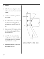
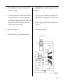
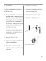
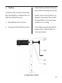
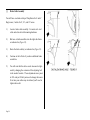
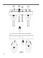
Rug Loom
User’s Manual
AVL Looms
3851 Morrow Lane, Suite #9
Chico, CA 95928-8305
Customer Service: 888 893-0913
Sales: 800 626-9615
EM: [email protected]
TABLE OF CONTENTS
Preface
1
Before You Begin
1
Tools
3
•
•
Necessary Tools
Helpful Tools
3
3
•
Figure 1 - Hardware Identification Chart
4
Hardware
•
Hardware Hints
5
5
Assembly Sequence
6
•
•
Side Frame Assembly
Figure 2 - Right Side Frame Assembly
11
12
•
•
Figure 3 - Left Side Frame Assembly
Lower Back
13
14
•
Figure 4 - Assembling Lower Left
Back Corner
14
•
•
Spring Lever Assembly
Harness Pulley Support Assembly
15
15
•
•
Square the Frame
Lower Front
16
16
•
•
Upper Back
Figure 5
17
17
Page TOC-1
•
Level the Frame
18
•
Figure 19
34
•
•
Dobby Assembly
Beater Assembly
18
18
•
•
Figure 20 - Brake Drag Strap
Figure 21 - Brake Cable Adjuster
35
35
•
•
Figure 6
Air System
19
20
•
•
Figure 22
Apron
36
37
•
•
Figure 7 - Dobby/Side View
Figure 8
20
21
•
Connect the Air System
•
Compressor
37
37
•
•
Figure 9 - Dobby/Front View
Figure 10 - Basic Rug Loom Air System
22
23
•
•
Set Main Air Pressure
System Test
38
38
•
•
Figure 11
Harnesses Assemblies
24
25
•
Add Oil
38
•
•
Figure 12
Cloth Storage Beam Assembly
27
28
•
•
Figure 13 - Cloth Storage Beam
Figure 14 - Installing Cloth Beam
28
28
•
•
Cloth Beam Assembly
Figure 15
29
30
•
•
Separation Rollers
Figure 16 - Installing Separation Roller
31
31
•
•
Worm Drive
Figure 17 - Cloth Storage Crankshaft
32
•
Assembly
Warp Beams
32
33
•
•
Figure 18 - Cloth Beam Handle
Brake Cable Assembly
33
34
Page TOC-2
PREFACE
BEFORE YOU BEGIN
We hope this manual will do three things for you:
1.
Guide you, step by step, through the assembly of your
loom — so you’ll be immediately satisfied with its
function.
2.
Help you learn about its various systems and components — so you’ll be an even more capable weaver.
3.
Inform you about the care and maintenance of your
loom — so you’ll enjoy a lifetime of dependable
service.
As we've already said, it’s important that you read this
manual and follow its instructions from beginning to end. A
quick read through before you actually pick up a tool will
give you a good overview of the whole assembly process.
The Table of Contents will direct you to each of the major
sections. You’ll note that at various places in the text, we’ve
inserted a [ ]. This is a reward box. Just add a checkmark
as you complete each segment of work. You’ll feel great and
it’ll help you stay organized.
Page 1
We know that sometimes you've just got to have a picture, so
we've included graphic support where it seems necessary.
You may wish to photocopy some of these illustrations and
bring them forward with you as you work through the
manual. This will save you a good deal of flipping back-andforth in search of that oh-so-helpful diagram. You'll probably
find, for example, that you need to refer constantly to the
Hardware Identification Chart (Figure 1) and Loom Illustrations (Figures 2 through 4).
One last bit of advice:
Even the narrower rug looms will require the efforts of
two people for many of the assembly operations.
Several of the components can be quite heavy, especially in longer lengths. PLEASE TAKE PRECAUTIONS TO PROTECT YOUR BACK, YOUR FINGERS,
AND FEET WHEN HANDLING THESE PARTS!
Now, read through the manual quickly, then we'll bolt the
whole shebang together.
Page 2
TOOLS
You’ll need a few basic hand tools to assembly your loom.
We recommend a couple of others that we think will make
your job easier.
Necessary Tools:
[ ]
[ ]
[ ]
[ ]
[ ]
[ ]
[ ]
[ ]
[ ]
thick)
[ ]
ratchet and sockets: 7/16”, 1/2”, and 9/16”
standard screwdriver
medium phillips screwdriver
hammer or mallet
8” or 10” adjustable end wrench
carpenter’s level
framing square
pliers
three wooden blocks or books (approximately 2”
step stool
Helpful Tools:
[ ]
[ ]
power screwdriver with assorted bits
extra ratchet and sockets
Page 3
HARDWARE IDENTIFICATION CHART - FIGURE 1
Page 4
HARDWARE
If you don't work with hardware, you may find some of the
terms a little mystifying. Not to worry, we've provided that
easy-to-use identification chart (Figure 1) to help you keep
things straight.
Hardware Hints:
A.)
If a bolt is a little tight going into a hole, give it a
light, friendly tap with a hammer.
B.)
To start the threads on a nut in a “nut access hole”
(Figure 4), you may need to hold the nut in place with
the end of a screwdriver or a finger tip.
C.)
Always have the large "nut access hole" facing toward
the inside of the loom unless otherwise specified.
D.)
Square nuts always go in "nut access holes" and do
not take a washer.
E.)
But, always put a washer under the head of a hex bolt.
Any nut that is NOT in an access hole also requires a
washer. This will prevent damage to the wood.
F.)
If you have trouble turning a screw into the wood on
your loom, try dressing the threads with a little bar
soap.
Page 5
ASSEMBLY
SEQUENCE
Your first task will be to construct the SIDE FRAMES, left
and right, to which you will add the various other loom parts.
As you work through the assembly sequence, you will add
components in the following order:
[
[
[
[
[
[
[
[
[
[
[
[
[
[
[
[
]
]
]
]
]
]
]
]
]
]
]
]
]
]
]
]
lower back
upper back
spring lever support assembly
harness pulley support assembly
cloth beam
square and level
cloth storage beam
worm drive assembly
beater assembly
dobby head
harness cables
harness frames
harness springs
air system
separation roller
warp beam
The following illustrations (OV-A through OV-P) are a pictorial overview of the sequence of steps necessary to put you
loom together. Please do not use these pictures as a manual.
They are for reference purposes only.
Page 6
Page 7
Page 8
Page 9
Page 10
[ ]
Side Frame Assembly (tool needed: 9/16” ratchet)
You’ll need an area roughly 10’ x 10’ in which to assemble
the side frames. If the floor is concrete, you may want to lay
a tarp down to protect the lacquer finish on the parts.
1.)
2.)
3.)
4.)
7.)
It’s puzzle time. Beginning with the longest part, 1L,
arrange each of the eight left side frame members as
shown in Figure 3.
8.)
Closely compare Figure 3 against each part. Verify
that the holes are lined up.
9.)
Use the appropriate bolts, “A” or “B”, to loosely
connect each part to its neighbors.
10.)
Go back and tighten the bolts (but not so tightly as to
crack the wood beneath the flat washers).
11.)
Remove the completed left side frame to make room
for the right.
12.)
Complete the right side frame in the same way.
Locate Box #1.
Remove the contents. Note that each component is
identified by number. These numbers correspond to
the Side Frame Assembly diagrams (Figures 2 and 3).
Arrange the parts at the periphery of your work area.
You will find it helpful to separate parts, left and right.
Also, orient them so that the large access holes face
up.
Check the contents of the hardware bag against its
packing list and group similar bolts together.
5.)
Each bolt should have been fitted at AVL with a lock
washer, a flat washer, and square nut, in that order.
6.)
Fit your ratchet with a 9/16” socket and leave it with
the hardware.
In the next assembly phase, you’ll hang various cross members between the side frames. As you progress, the loom
frame will become sturdier and free-standing. Be sure to
move the frame to its final position before it becomes too
heavy. A 12’ Rug Loom can weigh as much as a half-ton.
Moving the steel beams into place is heavy work, especially
for the wider looms, and we recommend that you have plenty
of help at hand at that point.
Page 11
Page 12
Page 13
[ ]
Lower Back
1.)
Find Box #2 and remove and organize its contents.
Note that the cross members have part names instead
of numbers.
2.)
Locate the cross member hardware pack. Sort and
verify its contents.
3.)
Move the left side frame into position and lay it on the
floor with the access holes facing up. The short,
round-topped, vertical member is at the front of the
loom.
4.)
Bring the Lower Back to the loom and place it on the
floor with the access holes facing what will be the
front of the loom (Figure 4).
5.)
Use two 3/8” x 4” hex bolt assemblies (bolt/lock
washer/flat washer/square nut) to secure the left end
of the Lower Back to the rear of the left side frame.
Snug the bolts down, but do not tighten.
6.)
Repeat for the right side frame. The frame will now
stand un-supported (see Figure 5).
Page 14
[ ]
Spring Lever Assembly
[ ]
Harness Pulley Support Assembly
1.)
Because each Rug Loom is unique, depending on
width and options, the Spring Lever Assembly may be
packed in a different box. However, the contents of
each box are listed on the outside. Locate the Spring
Lever Assembly.
1.)
Find the Harness Pulley Support Assembly. It is easily
identified by its three sets of black plastic pulleys.
2.)
Bring it to the loom and orient it so that the metal
identification plate faces front. One set of pulleys will
be offset to the far right side of the loom.
3.)
This assembly bolts into the loom from the top.
4.)
Select two 8” hex bolt assemblies and two 10-1/4” or
12-1/4” stud assemblies from your hardware assortment. The studs will have a nylock nut cemented at
one end.
5.)
You’ll now need to hoist the assembly into position
atop the left and right Top Horizontals. Be very
careful of your back; get extra help if you feel you
need it.
6.)
Raise the assembly into place and orient it over the
appropriate mounting holes in the Top Horizontals.
The ID plate should face forward.
7.)
Bolt it into place. The long studs insert at the rear
holes, the 8” hex bolts in the front.
2.)
3.)
Locate the appropriate mounting holes in the side
frames and pre-position four 4” hex bolt assemblies.
Bring the Spring Lever Assembly into position. Note:
it is correctly oriented if the chains hanging from the
levers face the side frames. If they are to the inside of
the loom. There should be a label affixed to the assembly that indicates the Top/Front.
4.)
Left the assembly into position and slide the bolts
home.
5.)
Add the nuts and snug the bolts.
Page 15
[ ] Square the Frame (tool needed: 25’ tape or
carpenter’s square)
In order for the loom to function well, it must be reasonably
square and level. We’ll check for squareness first. You may
do this with either a carpenter’s square or a 25’ tape measure.
1.)
2.)
Do the same from the Right Front Vertical to the
Left Front Vertical. Record and compare the
two measurements. When they are equal, the
frame will be square.
•
From opposing corners, bear against the frame
as needed to bring the frame to square.
•
When you have put the frame square (within 1/
8”), go back and tighten all the connecting
bolts.
Using a Carpenter’s Square:
•
Check the loom frame at the lower rear corners.
Bear against opposing corners to adjust the
frame until it comes into square.
•
Now, go back and firmly tighten all the cross
member bolts that you previously left only
snug.
[ ]
Lower Front (tool needed: 3 blocks or books)
1.)
Bring the Lower Front into position between the freestanding side frames. In this case, orient it so that the
access holes face the floor (Figure 5).
Using a Tape Measure:
•
Page 16
•
You will use the tape to check the loom’s diago- 2.)
nal measurements. First measure from the
inside bottom of the Left Front Vertical, to the
outside front of the right Rear Vertical. Record
your measurement.
3.)
Select four more 3/8” x 4” bolt assemblies and preposition the bolts in the attachment holes, from the
outside of each side frame.
Place blocks under each Front Vertical, left and right.
This will raise the front of the loom enough for you to
install nuts on the bolt ends where they emerge in the
blind access holes.
4.)
Place an additional block under the right end of the
Lower Front (Figure 5).
[ ] Upper Back (you’re quickly becoming a world class
loom builder)
5.)
Lift the left end of the Lower Front until its bolt holes
are opposite those in the side frame. Push the bolts
into position and add the square nuts (it’s tight on the
fingers, but this will be the only time you’ll be so
cramped). Snug, but don’t tighten.
1.)
Again, pre-position connecting bolt assemblies in the
appropriate holes at the upper rear of each side frame.
2.)
Bring the Upper Back to the loom and push the bolts
into place.
6.)
Repeat at the right end.
3.)
Add square nuts and snug.
7.)
Remove the blocks. You won’t need them again.
Page 17
[ ]
Level the Frame (tool needed: carpenter’s level)
1.)
Use the level to check the frame across the center of
the Front Harness Pulley Support.
4.)
Identify the mounting holes in the Right Side Frame,
align the bolts, and push the head into place (Figure
5).
5.)
If the bubble is more than slightly beyond the plumb
lines, you may need to shim one or more of the verticals. Failure to level the loom now may affect the
beater operation level. However, the frame needs to
be only reasonably level, not precisely level. You
needn’t be overly concerned unless your floor is
seriously cattywompus.
Add the nuts/washers and firmly tighten the head to
the frame.
[ ]
Beater Assembly
1.)
The Beater Assembly is quite heavy and you’ll need
help to install it! Note that the mounting brackets are
already in place on the side frames.
[ ]
Dobby Assembly
2.)
Bring the Beater Assembly to the front of the loom.
1.)
The Dobby Head is shipped in its own box. Please
locate it now.
3.)
2.)
Unpack the head and set aside the other box constituents (dobby bars, pegs, etc.). Bring the head to the
right side of the loom. The cable array is at the top of
the unit.
Untape the hardware bag and remove the four short
hex bolts with washers. Locate as well the four
wooden blocks we provided. Place two bolts and two
blocks on the floor to the outside of each side frame.
You will use these very soon.
4.)
Next, lift the Beater Assembly into position and bolt it
into the mounting brackets, using the four hex bolts
you’ve pre-positioned at each side of the loom. Leave
the end bolts loose for the moment — you still need to
adjust the height of the beater.
2.)
3.)
Page 18
The three attachment bolts are already in place in the
head. Remove the hex nuts and washers.
5.)
6.)
At each side of the loom, insert two blocks under the
slide rods, near the front and rear brackets. These
blocks are pre-cut to a particular dimension and will
establish the correct height of the beater. Let the
Beater Assembly rest on the blocks.
Tighten down the four end bolts that connect the slide
rods to the support brackets. Remove the blocks.
7.)
Move the rubber washers fore and aft, up to the brackets. You should have two washers to the front of the
beater and one aft.
8.)
Check the travel of the beater. It should move
smoothly front-to-back, without binding, and should
offer very little resistance. If you find that you need
to overcome resistance, another adjustment is in order.
Page 19
[ ]
Air System
You’ve now installed all the major framing members, the
Dobby, and the Beater Assembly. It’s a good time to mount
the various components that comprise the Air System, before
the interior of the loom becomes any more congested.
The Rug Loom will support a variety of pneumatic systems in
addition to the Basic Air System. If you purchased an Air
Advance, Air Shuttle, and/or an Air Beater, please refer to the
addenda provided separately with those systems. Otherwise,
you’ll have the Basic Air System.
1.)
Please unpack the basic components and lay them out
on the floor. They are joined by plastic air tubing and
you may think you’ve encountered an octopus, but the
whole array should assume shape without much difficulty once it’s out of the box. Note too, that the tube
ends are color coded to appropriate fittings, so even if
something does come undone, it will be easy enough
to reconnect later.
2.)
Identify each component against Figure 6. They are
individually labeled and there are corresponding
labels on the frame. It’s a simple matter of matching
item to location.
Page 20
Page 21
3.)
You will install the Air System in the following order:
Outside, Right Side Frame (below Dobby):
•
FRL (Filter/Regulator/Lubricator)
•
Main Air Valve
Inside, Right Side Frame:
•
Manifold (79)
•
Four-Way Piloted Valve (80)
•
Shuttle Valves (8’, 10’, 12’ looms only) (81)
•
Upper Brake Valve (82)
•
Lower Brake Valve (optional) (83)
•
Right Lower Brake Cylinder (optional)
•
Right Upper Brake Cylinder (24)
•
Left Lower Brake Cylinder (optional and 8’,
10’, 12’ looms)
•
Left Upper Brake Cylinder (optional and 8’,
10’, 12’ looms)
Freestanding:
•
Foot Control (you will have two controls with
8’, 10’, 12’ looms)
4.)
Page 22
The mounting screws for each air component are
taped to it. Please attach the individual elements now,
proceeding as suggested in the list above.
5.)
When all the components are in place, return and tie
the tubing into the pre-installed white plastic anchors
that you find at various places on the frame. We’ve
provided a number of plastic zip ties for this purpose
and a few extra anchors which you can use where
needed to keep things neat.
6.)
Finally, return and visually inspect each connection to
be sure that no air lines have come loose. If you find a
loose end, simply push it into the appropriately coded
connector until you feel it seat.
Page 23
Page 24
[ ]
Harness Assemblies (tool needed: phillips screwdriver)
1.)
Locate the Harness Cables, Heddles, Springs, and
Harness Frames.
2.)
You’ll need to load the heddles onto the harnesses
before you hang them. This is most comfortably done
on a table.
3.)
Lay a harness down and remove the Heddle Support
clips from the right or left end, upper and lower.
4.)
9.)
Repeat for each frame.
10.)
Use a phillips screwdriver to remove the two Harness
Cable Retainers that sit atop the inboard sets of Harness Pulleys. Or remove the front screw in each,
loosen the rear, rotate the retainer out of your way, and
place the loose screw back in its original hole until it’s
time to re-secure it. This will save you a lost screw
later.
11.)
Locate and unwrap the Harness Cables.
12.)
You will connect each harness cable to a corresponding cable emerging from the top of the Dobby.
13.)
To connect a cable, loosen the knurled locking sleeve
on the oval connecting link and slide it open. Use the
link to connect the Harness Cable to the right most
(rear most) Dobby Cable.
14.)
The Harness Cable now has two free ends, a long and
a short. String the cable over the three corresponding
pulleys in line with it. The short leg of the cable will
fall over the second pulley, the long over the third
pulley (account for “Y” on long looms).
Withdraw the Heddle Supports a few inches so the
ends are free of the harness frame.
5.)
Unlay a bundle of heddles opposite the free ends of
the supports.
6.)
The heddles are strung on cords. Tie each of the cords
into the holes at the ends of the Supports.
7.)
Transfer an appropriate number of heddles from the
bundle to the Heddle Supports. We provide 100
heddles per frame.
8.)
Loosen the cords, re-insert the supports, and add the
clips.
Page 25
15.)
Bring a harness frame to the loom and connect the
hanging cable ends into the screweyes in the top of its
frame. Note: each harness frame has a top and a
bottom. This will be indicated on the frame. If it’s
not, just remember that the Harness Cables should
hang perpendicularly when connected to a harness.
Another check: the screweyes on the tops of the
frames are set closest to the center, those on the bottom are further apart.
16.)
Note the array of Spring Levers suspended on axles
from the Spring Lever Supports. A chain hangs from
each lever. Find the two levers that are immediately
below the harness frame you just hung. Connect the
last link in each chain to the corresponding screw eyes
in the bottom of the harness.
17.)
Bring the bundle of springs with chains to the loom.
Select one of these assemblies. Connect the spring
end into the remaining screweye in either of the levers
and the chain end into the screweye opposite. You
may start left or right, just keep the order consistent as
you add each harness assembly.
18.)
Return now and hang and connect each remaining
Harness Frame.
Page 26
19.)
When you’ve installed all the Harness Frames, go
back and be sure that the cables are not twisted where
they cross the pulleys. Check too, that each cable is
properly bedded in its appropriate pulley set.
20.)
When you are satisfied that all is in order, replace the
Harness Pulley Retainers. Tighten them down just
enough that the felt strip on the bottom of the retainers
is slightly compressed by the pulley below it. The
pulley must be able to rotate as the harnesses lift or
you will experience undo wear on the cable.
Page 27
[ ]
Cloth Storage Beam Assembly
The beams you are about to install are extremely heavy and we advise you to have at least two robust adults on hand for
handling them. A third person may be required for beams longer than 8’.
Page 28
1.)
Locate the Cloth Storage Beam and the large Drive
Gear.
2.)
Find the separate box of pillow bearings and mounting
hardware.
3.)
You will first need to mount the Drive Gear to the right
axle of the Cloth Storage Beam.
4.)
Remove the hardware bag marked Cloth Storage Beam
from the box of pillow bearings.
5.)
6.)
7.)
Mount the gear to the axle. First slide the key into the
keyway; then slip the gear over the axle and align its
slot with the key; push the gear on and flush against
the end of the beam; finally, tighten down the set
screw.
Bring the beam to the front of the loom and orient it so
that the gear is on the right (dobby) side.
On the loom, identify the mounting holes for the
pillow blocks. There are two each in the left and right
Cloth Storage Supports (Figure 2, 7R for example).
8.)
Slip the pillow blocks onto the beam axles. The
grease fitting on the right block (Dobby side) should
point to the rear of the loom; that on the left, to the
front.
You’ll need to lift the beam and insert its left end
through the frame. This will give you clearance to
bring the right end into position over the mounting
holes.
Position the pillow blocks over their mounting holes.
You’ll note that we have scribed index lines into the
frame. Align the blocks with these lines.
9.)
Add the bolts and firmly bolt the pillow blocks in
place.
[ ]
Cloth Beam Assembly
Again, this beam is quite heavy and you’ll need to observe
the usual precautions.
1.)
Bring the Cloth Beam to the front of the loom. It is
symmetrical, end-to-end.
Page 29
2.)
3.)
Page 30
Wooden blocks should already be on the axles at both
ends. Untape the hardware bags from the beam, remove the four square nuts, and insert the bolts into the
holes in the blocks, from the recessed side.
These blocks will rest atop the Front Verticals (Figure
15). Lift the beam into position now. Engage the bolt
ends in the appropriate holes in the verticals.
4.)
Add the four nuts and tighten down the block on one
end.
5.)
Rotate the beam by hand a time or two to settle the
remaining block. Tighten.
6.)
Rotate the beam again. If it rubs at the ends, loosen
one side and make whatever adjustment is warranted.
5.)
Install the two retainers as shown in.
You will have one Separation Roller for each Warp Beam.
One Warp Beam, one roller.
6.)
Place the roller in its pockets and rotate the retainers
up. Secure the bolt in each retainer.
1.)
7.)
Add the upper bolt at each retainer and tighten.
8.)
Repeat for the second roller (if you have one).
[ ]
Separation Rollers
The Separation Rollers fit into the semicircular pockets in the Rear Verticals. If you plan to use your Warp
Beam in the upper position, its Separation Roller will
fit the inside pockets. If you will use your Warp Beam
in the lower position, place the Separation Roller in
the outside pockets. Neither position offers a weaving
advantage, but many people find it easier to work
from a high beam when warping.
If you plan to mount two Warp Beams, you have no
decisions to make — the Separation Rollers are exactly alike and you’ll use both.
2.)
Bring a roller to the rear of the loom.
3.)
Untape the hardware bag. In it you will find two flat
retainers and four bolt assemblies.
4.)
Remove the hex nut and all but one flat washer on
each bolt; insert a bolt with washer into the lower hole
in each bracket.
Page 31
[ ]
Worm Drive
Now you will add the drive mechanism that turns the beam.
You will need two 3/4” wrenches to accomplish this.
1.)
Find the drive mechanism and remove the pivot bolt,
pivot block, and wooden spacer.
2.)
Fasten the pivot to the loom as shown in (Figure 17).
3.)
Untape the four wood screws you find taped to the
Sliding Bracket. Use these to secure the bracket to the
inside Front Vertical.
4.)
Note that the worm lays atop the large drive gear.
Move the worm down until the two gears mesh. You
may need to pull out on the small spring pin you see at
the front of the bracket. Withdraw it enough to free
the slide plate so that you can move the worm down.
Once done, release the pin into it’s hole.
5.)
Now thread the star handle down tightly. This handle
will allow you to lock the worm up and away from the
gear if you need to disengage the drive. The pull pin
will keep the gears seated when the mechanism is
under strain, however, you should also keep the star
handle firmly tightened when you are weaving.
Page 32
6.)
Connect the Cloth Storage Crank to the front of the
drive shaft (see Figure 18).
7.)
Turn the crank in both directions. It should operate
smoothly and the gears and beam should turn easily.
[ ]
Warp Beams
Last of the heavy lifting. You will have a Sectional Warp
Beam, a Plain Warp Beam, or a combination of beams. Regardless, they all mount in the same way.
1.)
Bring a Warp Beam to the rear of the loom.
2.)
Here again you’ll find a Pillow Block on each axle.
3.)
Untape the hardware, strip the bolts of their washers,
and insert them into the mounting holes in the blocks.
4.)
Remember, you have a choice of positions for your
Warp Beams. You decided once when you installed
the Separation Roller(s), but if you want to change
your mind now, no one is looking.
5.)
Lift the Warp Beam into position and push the bolts
through the Verticals. Add the flat washers, lock
washers, nuts, then tighten.
Page 33
[ ]
Brake Cable Assembly
You will have one brake cable per Warp Beam for 4’ and 6’
Rug Looms; 2 cables for 8’, 10’, and 12’ looms.
1.)
Locate a brake cable assembly. It consists of a steel
cable and a bracket with mounting hardware.
2.)
Bolt one or both assemblies into the right side frame
as indicated in (Figure 19).
3.)
Route the brake cable(s) as indicated in (Figure 21).
4.)
Continue to the left side if you have additional brake
assemblies.
5.)
You will note that the cables can be loosened or tightened by changing the extension of the adjusting bolt
in the anchor brackets. These adjustments were preset
at AVL and you’ll likely not need to change them now.
Over time your cables may stretch and you’ll need to
tighten them a bit.
Page 34
[ ]
Brake Drag Strap
On the opposite side of the Brake Assembly is the Brake
Drag Strap. It is used to help keep the beam from twisting.
See Figure 20 for details.
Page 35
Page 36
[ ]
Apron
Your Rug Loom is provided with a heavy canvas Cloth Storage Apron. This provides a convenient way to tie off your
warp and conserves warp length, several yards of which
would be lost if you tied directly to the Cloth Storage Beam.
1.)
Locate and unlay the apron.
2.)
Starting about 1/4” from either end of the Cloth Storage Beam, secure the velcro strip of the apron to that
on the beam. Take care to keep this interface straight
and free of wrinkles.
3.)
You have also been provided with several long steel
rods. Find one now and slide it through the loops at
the other end of the apron. Leave the other Apron Rod
aside for now.
4.)
Use the Cloth Storage Crank to roll the apron onto the
beam.
5.)
You will be instructed in the Weaving Section about
tying-on to the apron.
[ ]
Connect the Air System
Compressor
It’s a good time to connect the air delivery line from the
compressor to the FRL. Installations differ; for example, the
air line from your compressor to your loom may be copper
pipe, PVC, or flexible hose. If you are using a rigid tubing,
we recommend that you fit at least a few feet of flexible hose
between the FRL connection and the main line. This will
prevent strain at the connection if the loom moves during
weaving.
We recommend that you use quick disconnect fittings to
connect the air hose to the intake port of the FRL. Your
compressor supplier, or any industrial tool or agricultural
supply, can help you with this. The fitting should be male
with 3/8” NPT threads. It’s helpful if you buy a fitting that
already has a sealant applied to its threads. Otherwise, wrap
the threads with Teflon tape to avoid a leak.
Please do not use pipe dope; it becomes scaly and can contaminate the air components.
You are so almost done! It’s a loom! It’s a loom! — and
there only a few remaining details to attend.
Page 37
Set Main Air Pressure
Add Oil
We pre-set the pressure at the FRL at 75 p.s.i. Please check it
now and re-calibrate the dial if necessary. Your loom will
operate at between 75 and 120 p.s.i., but it’s best to start at
the lower setting.
We provided you with a small bottle of lubricating oil. Consult the manufacturer’s instruction sheet for an explanation
of how to add oil at the FRL. Once you’ve added the oil, set
the lubrication meter at it lowest value. Your air system
requires almost no oil and too much can foul the system.
System Test
This is your first opportunity to test the loom’s function.
This test will establish that your air connections are tight,
that the harnesses transit smoothly, and that the Warp Beam
Brakes are working. We’ve pre-adjusted the operating
speeds and pressures, but you may need to add a few minor
tweaks to achieve a particular result. It’s always possible
that something was put out of adjustment in handling.
1.)
Put the Main Air Valve handle in the OFF position.
2.)
Turn on the compressor.
3.)
Listen for air leaks in your main air delivery line.
4.)
Open the Main Air Valve.
Page 38