1
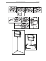
GEO S12 Series
Geo S1210 & Geo S1230 Tangent Array Modules
Geo S12 Analog TD Controller
User Manual
GEO S12 Series User Manual V1.04
Date: 31/08/2010
Page 2/113
PLEASE READ CAREFULLY BEFORE PROCEEDING
GEO Technology is radically new thinking
The GEO R&D Project has, to date, resulted in the following patent applications:
•
The GEO Hyperboloid Reflective Wavesource™ differs radically from the megaphone-variant
type horns you know and love (or hate). “Tried and true” methods will produce entirely
unexpected results. HRW technology produces precise and predictable results.
•
The Configurable Directivity Flange. A waveguide that allows the operator to alter its behaviour.
An unprecedented NEXO development that is easy to use – once you know how and when.
•
The Directivity Phase Device needs no operator input to function, but it is reassuring to know that
the coupling of the midrange of the system is considered as important as the high frequencies…
•
DSP-driven Directional Sub-bass devices are a new approach to controlling LF/VLF acoustic
energy.
GEO is not hard to use when you understand how…
The technology behind GEO is revolutionary, but it is grounded in years of practical experience with the
problems of delivering high quality professional sound to large audiences at high SPL levels. The GEO
toolbox includes GEOSoft -a simple yet powerful and highly predictive design tool. The array assembly
system is keyed to the design software and will easily enable you to deploy your design with great
precision. The NX242 Digital TDcontroller provides driver protection and system optimization as well as
DSP-driven cardioid pattern control for the CD18, GEO SUB and RS series Directional Subwoofers.
GEO is a high precision system
The GEO HRW™ controls acoustic energy more precisely than other multiple element waveguides. It
also makes GEO less forgiving of mistakes. Whilst conventional horns never combine into a coherent
array, they may deliver acceptable results even if the design and deployment of the system is less than
optimal. This is not the case with GEO where careless installation produces catastrophic results.
A GEO Tangent Array is not a “line array”
GEO Technology is equally effective in designing and deploying tangent horizontal arrays or curved
vertical arrays. For best results in a specific application the user needs to know how multi-speaker
arrays interact with audience geometry, along with the benefits and drawbacks of curved vertical arrays
and horizontal arrays.
Curved tangent arrays require different design techniques
For the past 20 years, sound reinforcement professionals have worked with horizontal arrays that use
conventional horns to deliver [more or less] ‘equal power to equal angles’. Curved vertical arrays are
designed to deliver [more or less] equal power to equal areas’. When arrays use conventional horns,
the lack of precision, overlap and interference masks errors in array design and aiming. The highly
precise GEO wavesource responds accurately, consistently and predictably to the design and
deployment of a curved vertical tangent array. This is why the GEO rigging system is designed to
control angular splay to 0.01° precision.
GEO curved tangent arrays require different operational techniques
Over the years, system designers and operators have developed a number of signal processing
techniques to disguise and partly overcome the limitations of horn design. “Frequency shading,”
“amplitude shading,” “system tuning,” all of these are tools of the advanced sound system operator.
NONE OF THESE TECHNIQUES ARE APPLICABLE TO GEO TANGENT ARRAYS. Instead of
enhancing the array’s performance they will severely degrade it.
Take time to learn how to get great results with GEO Technology. It is an investment that will pay off in
more satisfied clients, more efficient operating procedures and more recognition for your skill as a
sound system designer and operator. A comprehensive understanding of GEO theory, tangent arrays,
and specific features of the GEO S12 Series will help you to operate your system at its full potential.
PLEASE READ CAREFULLY BEFORE PROCEEDING
Page 3/113
PLEASE READ CAREFULLY BEFORE PROCEEDING
BASIC PRECAUTIONS
Do not open the speaker system or attempt to disassemble the internal parts or modify them in any
way. The speaker system contains no user-serviceable parts. If it should appear to be malfunctioning
or damaged, discontinue use immediately and have it inspected by qualified NEXO service personnel.
Water exposure: Do not expose the speaker system to direct rain, do not use it near water or in wet
conditions. Do not place containers with liquid on speaker system as they might spill into openings. If
any liquid such as water seeps into the speaker system, have it inspected by qualified NEXO
personnel.
SYSTEM DEPLOYMENT SAFETY RULES
Read User Manual before deployment. Before use of enclosed speaker system,
please ensure that anyone involved in system deployment understands the rigging –
stacking – pole mounting safety rules as described in the speaker system User Manual.
Failure to do this exposes people to potential injury or death.
Always consult qualified NEXO personnel if the device installation requires construction work and make
sure to observe the following precautions:
Mounting precautions
-
choose mounting hardware and an installation location that can support the weight of the speaker
system;
-
do not use speaker system handles for suspended installation;
-
do not expose speaker system to excessive dust or vibration, or extreme cold or heat to prevent
possibility of component damage;
-
do not place the speaker system in an unstable position from which it might fall accidentally;
-
if speaker systems uses a stand, ensure that stand specifications are adapted, and that stand
height does not exceed 1.40m/55”; never move the stand while the speaker is in position.
Connection and powering precautions
-
remove all connected cables before moving the speaker system;
-
turn off AC power of all power amplifier units before connecting the speaker system;
-
when turning on the AC power to the audio system, always turn on the power amplifier last; when
turning the AC power off, always turn off the power amplifier first;
-
when used in cold conditions, a gradual power ramp up should applied to the system on an 5 mn
period to allow the loudspeaker components to stabilize during the very first minutes of usage.
Inspect the speaker system periodically.
Page 4/113
PLEASE READ CAREFULLY BEFORE PROCEEDING
SAFETY INSTRUCTIONS FOR NEXO TD CONTROLLERS
NEXO ANALOGUE PSTDCONTROLLERS, NX242 DIGITAL CONTROLLER,
NXAMP4x1 AND NXAMP4x4 POWERED CONTROLLERS ARE CLASS 1
APPARATUS AND MUST BE EARTHED.
THE GREEN AND YELLOW WIRE OF THE MAINS CORD MUST ALWAYS BE CONNECTED TO AN
INSTALLATION SAFETY EARTH OR GROUND. THE EARTH IS ESSENTIAL FOR PERSONAL
SAFETY AS WELL AS THE CORRECT OPERATION OF THE SYSTEM, AND IS INTERNALLY
CONNECTED TO ALL EXPOSED METAL SURFACES.
-
Read these instructions.
-
Keep these instructions.
-
Heed all warnings.
-
Follow all instructions.
-
Do not use this apparatus near water.
-
Clean only with dry cloth.
-
Do not block any ventilation openings. Install in accordance with the manufacturer’s instructions.
-
Do not install near any heat sources such as radiators, heat registers, stoves, or other apparatus
(including amplifiers) that produce heat.
-
Do not defeat the safety purpose of the polarized or grounding-type plug. A polarized plug has two
blades with one wider than the other. A grounding type plug has two blades and a third grounding
prong. The wide blade or the third prong are provided for your safety. If the provided plug does not
fit into your outlet, consult an electrician for replacement of the obsolete outlet. (US market)
-
Protect the power cord from being walked on or pinched particularly at plugs, convenience
receptacles, and the point where they exit from the apparatus.
-
Only use attachments/accessories specified by the manufacturer.
-
Unplug this apparatus during lightning storms or when unused for long periods of time.
-
Refer all servicing to qualified service personnel. Servicing is required when the apparatus has
been damaged in any way, such as power-supply cord or plug is damaged, liquid has been spilled
or objects have fallen into the apparatus, the apparatus has been exposed to rain or moisture, does
not operate normally, or has been dropped.
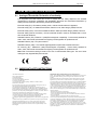
CAUTION
RISK OF ELECTRIC SHOCK
DO NOT OPEN
The lightning flash with arrowhead
symbol, within an equilateral triangle
is intended to alert the user to the
presence of uninsulated “dangerous
voltage” within the product's
enclosure that may be of sufficient
magnitude to constitute a risk of
electric shock to persons.
WARNING: To reduce the risk of fire or electric shock,
do not expose this apparatus to rain or moisture.
To avoid electrical shock, do not remove covers.
Dangerous voltages exist inside.
Refer all servicing to qualified personnel only.
The exclamation point within an
equilateral triangle is intended to
alert the user to the presence of
important operating and
maintenance (servicing) instructions
in the literature accompanying
the appliance.
PLEASE READ CAREFULLY BEFORE PROCEEDING
Page 5/113
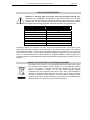
HIGH SOUND PRESSURE LEVELS
Exposure to extremely high noise levels may cause permanent hearing loss.
Individuals vary considerably in susceptibility to noise-induced hearing loss but nearly
everyone will lose some hearing if exposed to sufficiently intense noise for a sufficient
period of time. The U.S. Government’s Occupational and Health Administration (OSHA)
has specified the following permissible noise level exposures: Sound Duration Per
Day In Hours
Sound Level dBA, Slow Response
8
90
6
92
4
65
3
97
2
100
1½
102
1
105
½
110
¼ or less
115
According to OSHA, any exposure in excess of the above permissible limits could result in some
hearing loss. Ear plugs or protectors to the ear canals or over the ears must be worn when operating
this amplification system in order to prevent permanent hearing loss, if exposure is in excess of the
limits as set forth above. To ensure against potentially dangerous exposure to high sound pressure
levels, it is recommended that all persons exposed to equipment capable of producing high sound
pressure levels such as this amplification system be protected by hearing protectors while this unit is in
operation.
DISPOSAL OF OLD ELECTRICAL & ELECTRONIC EQUIPMENT
This symbol on the product or on its packaging indicates that it shall not be treated
as household waste. Instead it shall be handed over to the applicable collection
point for the recycling of electrical and electronic equipment. By ensuring this
product is disposed of correctly, you will help prevent potential negative
consequence for the environment and human health, which could otherwise be
caused by inappropriate waste handling of this product. The recycling of materials
will help to conserve natural resources. For more detailed information about
recycling of this product, please contact your local city office, your household waste
disposal service or the shop where you purchased the product.
Page 6/113
CONTENTS
CONTENTS
PLEASE READ CAREFULLY BEFORE PROCEEDING .................................................................................... 3
CONTENTS ......................................................................................................................................................... 6
1
2
Introduction ............................................................................................................................................. 10
GEO S12 General Set-up Instructions ................................................................................................... 13
2.1
3
2.1.1
GEO S12 connectors ............................................................................................................... 13
2.1.2
Configuring Geo S12 for Passive or Active Mode..................................................................... 13
2.1.3
Cabling ..................................................................................................................................... 13
2.1.4
Example: .................................................................................................................................. 14
Amplifier Selection for use with GEO S12s........................................................................................... 15
3.1
GEO S12 recommended amplification .............................................................................................. 15
3.1.1
Current rating ........................................................................................................................... 15
3.1.2
Amplifier settings ...................................................................................................................... 15
3.1.3
Example ................................................................................................................................... 17
3.2
4
Speaker connection .......................................................................................................................... 13
GEO S12s and NXAMP TDControllers ............................................................................................. 17
3.2.1
NXAMP connectors .................................................................................................................. 17
3.2.2
GEO S12s and NXAMP recommended configurations............................................................. 18
GEO S12 Setups on NEXO TD Controllers ............................................................................................ 19
4.1
Digital NX242-ES4 and NXAMP TDControllers ................................................................................ 19
4.2
Analogue GEOS12 TDController ...................................................................................................... 20
5
Connection diagrams.............................................................................................................................. 20
5.1
GEO S12 & RS15 with GEOS12 TDController (Mono Omni Mode) .................................................. 20
5.2
GEO S12 / NX242-ES4 (4 channels passive mode) ......................................................................... 21
5.3
GEO S12 / ALPHA S2 / NX242-ES4 (Stereo passive mode) ............................................................ 22
5.4
GEO S12 / CD18 / NX242-ES4 (Stereo passive mode) .................................................................... 23
5.5
GEO S12 / GEO SUB / NX242-ES4 (Stereo passive mode)............................................................. 24
5.6
GEO S12 / NXAMP4x1 (Bridge Stereo - Passive mode)................................................................... 25
5.7
GEO S12 / NXAMP4x1 (Bridge Stereo - Active mode) ..................................................................... 26
5.8
GEO S12 / NXAMP4x4 (4 Channels - Passive mode) ...................................................................... 27
6
5.9
GEO S12 / NXAMP4x4 (Stereo Active mode)................................................................................... 28
NS-1 Simulation software ....................................................................................................................... 29
7
Configurable Directivity Device.............................................................................................................. 30
8
7.1
Installing & removing GEO’s Configurable Directivity flanges ........................................................... 30
7.2
When & where to use Configurable Directivity flanges...................................................................... 31
GEO S12 hardware setup procedure ..................................................................................................... 32
8.1
SAFETY FIRST ................................................................................................................................ 32
8.1.1
Flown Systems Safety.............................................................................................................. 32
8.1.2
Ground Stacking Safety ........................................................................................................... 33
8.1.3
Contacts ................................................................................................................................... 34
CONTENTS
8.2
General Description .......................................................................................................................... 35
8.2.1
Described configurations.......................................................................................................... 36
8.2.2
WARNINGS ON GEO S12 ACCESSORIES ............................................................................ 37
8.3
GEO S12 in fixed installations .......................................................................................................... 38
8.3.1
Fixed installation Accessories and kits ..................................................................................... 38
8.3.2
Single GEO S12 rigidly mounted on a wall or a ceiling (vertical or horizontal).......................... 39
8.3.3
Single GEO S12 cable mounted on a wall or a ceiling (vertical or horizontal) .......................... 40
8.3.4
GEO S12 vertical array rigidly mounted on a ceiling ................................................................ 41
8.3.5
GEO S12 vertical array cable mounted on a ceiling ................................................................. 43
8.3.6
GEO S12 horizontal array rigidly mounted on a ceiling ............................................................ 44
8.3.7
8.4
9
Page 7/113
GEO S12 horizontal array cable mounted on a ceiling ............................................................. 46
GEO S12 in touring applications ....................................................................................................... 47
8.4.1
Touring Accessories................................................................................................................. 47
8.4.2
Single GEO S12 on speaker stand or on RS15 horizontally..................................................... 48
8.4.3
Single GEO S12 flown vertically............................................................................................... 50
8.4.4
Single GEO S12 flown horizontally........................................................................................... 51
8.4.5
Two GEO S12 on wind-up stand or on RS15 horizontally ........................................................ 52
8.4.6
Two GEO S12 flown horizontally.............................................................................................. 56
8.4.7
Two or more GEO S12 flown vertically..................................................................................... 57
8.4.8
Three or more GEO S12 flown horizontally .............................................................................. 60
8.4.9
Ground stacked GEO S1210.................................................................................................... 64
8.5
Testing and Maintenance of the system ........................................................................................... 68
NEXO Analogue Geo S12TD Controller................................................................................................. 69
9.1
Analogue TDcontroller Declaration of conformity.............................................................................. 69
9.2
IMPORTANT SAFETY INSTRUCTIONS .......................................................................................... 69
9.3
Analogue TDcontroller Setting-Up Advice......................................................................................... 70
9.3.1
Mains Power ............................................................................................................................ 70
9.3.2
Voltage setting ......................................................................................................................... 70
9.3.3
Mounting the TDcontroller in a rack (Grounding, shielding & safety issues) ............................. 70
9.3.4
Fuse ......................................................................................................................................... 70
9.3.5
Recommendations for wiring the sense lines ........................................................................... 71
9.3.6
Recommendations for wiring the audio outputs........................................................................ 71
9.3.7
Electromagnetic environments ................................................................................................. 71
9.3.8
Analogue signal cables ............................................................................................................ 71
9.4
Analogue TDcontroller USER GUIDE ............................................................................................... 72
9.4.1
Read before use....................................................................................................................... 72
9.4.2
Front Panel .............................................................................................................................. 73
9.4.3
Rear Panel ........................................................................................................................74
9.5
TDcontroller REFERENCE GUIDE ................................................................................................... 75
9.5.1
Linear section........................................................................................................................... 75
9.5.2
Servo Control section ............................................................................................................... 75
Page 8/113
10
CONTENTS
NEXO NX242-ES4 Digital Controller for GEO S12 ............................................................................ 77
10.1
NX242 Proprietary Functions ............................................................................................................ 77
10.1.1
Upgradable Firmware............................................................................................................... 77
10.1.2
EQ & Filtering........................................................................................................................... 77
10.1.3
Protection ................................................................................................................................. 78
10.2
Trouble shooting ............................................................................................................................... 79
10.2.1
Operation of Multiple TDcontrollers output channels ................................................................ 79
10.2.2
Amplifier Power (MENU 2.7) .................................................................................................... 79
10.2.3
Amplifier Gain (MENU 2.6) ....................................................................................................... 79
10.2.4
Gains........................................................................................................................................ 79
10.2.5
Delays ...................................................................................................................................... 80
10.2.6
Reversed Cardioid Pattern ....................................................................................................... 80
10.2.7
Using the wrong NX242 setups for a given cabinet .................................................................. 80
10.2.8
Connections ............................................................................................................................. 80
11
System alignment guidelines............................................................................................................. 81
11.1
GEO S12 Vertical Cluster design...................................................................................................... 81
11.2
Stacked RS15 / CD18 / S2 / GEO SUB and Flown GEO S12........................................................... 81
11.3
Driving the GEO SUB’s from the AUX send...................................................................................... 82
11.4
Recommended installation tools and equipment............................................................................... 82
GEO S12 – RS15 / CD18/S2/GEOSUB System Check List ............................................................... 84
12.1
Are the NX242 Digital TDcontrollers properly configured? ................................................................ 84
12
12.1.1
12.2
NX242 settings ......................................................................................................................... 84
Are the amplifiers properly configured?............................................................................................. 84
12.3
Are the amps and the NX properly connected? ................................................................................ 84
12.4
Are the speakers properly connected and angled ? .......................................................................... 85
12.5
Final Pre-Sound Check Check.......................................................................................................... 85
Technical Specifications .................................................................................................................... 86
13
13.1
GEO S1230 Module.......................................................................................................................... 86
13.1.1
System specifications............................................................................................................... 86
13.1.2
Dimensions .............................................................................................................................. 87
13.1.3
Diagrams.................................................................................................................................. 87
13.2
GEO S1210 Module.......................................................................................................................... 88
13.2.1
System specifications............................................................................................................... 88
13.2.2
Dimensions .............................................................................................................................. 89
13.2.3
Diagrams.................................................................................................................................. 89
13.3
GEO S12 Touring Applications Accessories ..................................................................................... 90
13.3.1
GPT- BUMPER ........................................................................................................................ 90
13.3.2
GEO S12 Rigging Plates .......................................................................................................... 91
13.3.3
Tension Mode Link Bars for GPT-XBOW ................................................................................. 92
13.3.4
Lifting Ring ............................................................................................................................... 93
13.3.5
Truss hook for GPT-PSBRK or GPT-SSBRK ........................................................................... 94
13.3.6
Truss hook for single vertical GEO S12.................................................................................... 95
13.3.7
“U” Bracket for single vertical GEO S12 ................................................................................... 96
CONTENTS
13.3.8
U” Bracket for two vertical GEO S12 ........................................................................................ 97
13.3.9
Ground Stacking Device for up to 6 GEO S1210...................................................................... 98
13.4
GEO S12 Fixed Installations Accessories......................................................................................... 99
13.4.1
GEO S12 Bumper .................................................................................................................... 99
13.4.2
GEO S12 Connecting Plate 1................................................................................................. 100
13.4.3
GEO S12 Connecting Plate 2................................................................................................. 101
13.4.4
GEO S12 Connecting Plate 3................................................................................................. 102
13.4.5
Single GEO S12 “U” Bracket .................................................................................................. 103
13.4.6
“L” Bracket for cable suspension ............................................................................................ 104
13.4.7
“U” Bracket for rigid suspension ............................................................................................. 105
13.4.8
GEO S12 Push-Pins (04VXT-BL820) ..................................................................................... 106
13.5
GEO S12 Analogue TDcontrollers .................................................................................................. 107
13.5.1
Specifications ......................................................................................................................... 107
13.5.2
Front and Rear Panel view..................................................................................................... 107
13.6
NX242 TDcontroller with NX-Tension Card..................................................................................... 108
13.6.1
Specifications ......................................................................................................................... 108
13.6.2
Front and Rear Panel view..................................................................................................... 108
13.6.3
Block Diagram........................................................................................................................ 109
14
15
Page 9/113
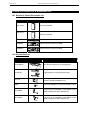
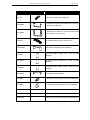
GEO S12 Series Parts & Accessories List ...................................................................................... 110
14.1
Modules & Control Electronics List ................................................................................................. 110
14.2
Accessories List.............................................................................................................................. 110
USER NOTES..................................................................................................................................... 112
Page 10/113
1
INTRODUCTION
INTRODUCTION
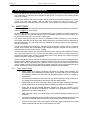
Thank you for selecting a NEXO GEO S12 Series Tangent Array System. This manual is intended to
provide you with necessary and useful information about your GEO S12 System, which includes the
following products:
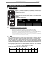
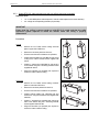
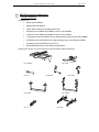
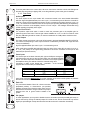
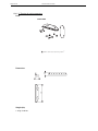
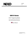
•
•
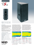
GEO S1230 is a 30° Tangent Array Module.
It comprises 1x12” (30cm) Neodynium 16
ohms LF/MF driver and 1x3” voice coil, 1.4”
Throat 16 Ohm HF Driver loaded by a 28.5°
Hyperboloid Reflective Wavesource™.
•
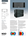
GEO S1210 is a 10° Tangent Array Module.
It comprises 1x12” (30cm) Neodynium 16
ohms LF/MF driver and 1x3” voice coil, 1.4”
Throat 16 Ohm HF Driver loaded by a 5°
Hyperboloid Reflective Wavesource™.
GEO S12 Accessory Range. a full range of accessories that provides safe, flexible and simple
means of installing Geo S12 Tangent Arrays in fixed installation as well as in touring applications.
INTRODUCTION
Page 11/113
As for all NEXO systems, GEO S12s are controlled, powered and monitored by dedicated NEXO
TDControllers:
•
GEO S12 TDController is based on PS analogue TDController design, and provides full control
for RS15 subwoofer in omnidirectional mode associated to Geo S12. It has 2 analogue inputs
(Left and Right) and 3 analogue outputs (RS15 Mono Omni, GeoS12 Left and GeoS12 Right);
•
NX242-ES4 Digital TDController provides comprehensive control of GEO S12 loudspeakers in
TM
multiple configurations. It allows Ethersound digital audio networking, as well as remote control
for all units in the network. It has 2 analogue / 4 digital inputs and 4 analogue / 4 digital outputs;
IMPORTANT
NX242 must be equipped with NX-Tension Card (ES4 or CAI) to access GEO S12 setups
•
NXAMP4x1 and NXAMP 4x4 are Powered Digital Controllers, providing full control and
amplification for RS15 in multiple configurations. Both devices feature 4 analogue inputs and 4
speaker outputs. When equipped with optional card, 4 digital inputs in EthersoundTM digital audio
network format as well as remote control for all units in the network become available.
For a complete description of these controllers, please refer to User Manuals. The NX242 and NXAMP
DSP algorithms and parameters are fixed in software and updated regularly: Please consult the NEXO
web site (www.nexo.fr) for the latest software releases.
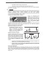
GeoD Passive mode
Crossover 80Hz
Page 12/113
INTRODUCTION
•
NS-1 simulation software (previously GEOSoft2) assists in the design and implementation of
vertical tangent GEO arrays. Please consult the NEXO web site (www.NEXO.fr or www.NEXOsa.com) for the latest software releases.
Please devote your time and attention to reading this manual. A comprehensive understanding of GEO
theory, tangent arrays and specific features of GEO S12 will help you to operate your system at its full
potential.
GEO S12 GENERAL SET-UP INSTRUCTIONS
2
Page 13/113
GEO S12 GENERAL SET-UP INSTRUCTIONS
2.1
Speaker connection
2.1.1
GEO S12 connectors
GEO S12 is connected with Speakon NL4FC plugs (not supplied). A wiring
diagram is printed on the connection panel located on the back of each
cabinet.The 4 pins of the 2 Speakon sockets identified in / out are connected in
parallel within the enclosure.
Either connector can be used to connect amplifier or to link to an additional Geo
S12 cabinet or to link to an optional Sub (if present). Therefore, a single 4conductor cable can connect two amplifier channels to various Geo S12 and/or
Sub Bass.
Connectors are wired as follows:
Speakon
Passive
Active
Connector
Mode
Mode
Not Connected
Not Connected
Geo S12 (-)
Geo S12 (+)
Geo S12 LF (-)
Geo S12 LF (+)
Geo S12 HF (-)
Geo S12 HF (+)
Ö
Ö
Ö
1(-)
1(+)
2(-)
2(+)
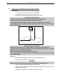
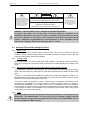
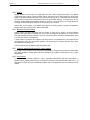
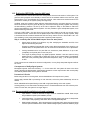
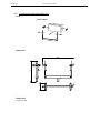
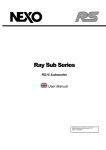
2.1.2
2.1.3
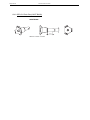
Configuring Geo S12 for Passive or Active Mode
•
Remove the six TORX screws that hold the connector panel (figure next page);
•
Remove the connector panel so that filter WAGO connectors become accessible;
•
In Passive Mode, connector A (from filter) should be inserted in connector B (PCB “Passive In”),
and Connector D (“Passive Out”) should be connected to speakers via connector C.
•
In Active Mode, WAGO Connector A (from filter) should be directly connected into to speakers via
connector C (PCB connectors B & D are then unused).
Cabling
NEXO recommends the exclusive use of multi-conductor cables to connect the system: the cable kit is
compatible with all the cabinets, and there is no possible confusion between LF, MF and HF sections.
Cable choice consists mainly of selecting cables of the correct sectional dimension (size) in relation to
the load resistance and the cable length. Too small a cable section will increase both its serial
resistance and its capacitance; this reduces the electrical power delivered to the loudspeaker and can
also induce response (damping factor) variations.
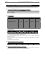
For a serial resistance less or equal to 4% of the load impedance (damping factor = 25), the maximum
cable length is given by:
Lmax = Z x S
S in mm2, Z in Ohm, Lmax in meters
The table below indicates these values, for 3 common sizes.
Load Impedance (Ω)
2
Cable section
Maximum Length (meters)
3
1,5 mm² (AWG #14)
3
4.5
4
6
6
8
12
16
9
12
18
24
2,5 mm² (AWG #12)
5
7.5
10
15
20
30
40
4 mm² (AWG #10)
8
12
16
24
32
48
64
Page 14/113
2.1.4
GEO S12 GENERAL SET-UP INSTRUCTIONS
Example:
•
GEO S12 has a 16 Ohms nominal impedance in passive mode, so 4x Geo S12 wired in parallel
2
will present a 16/4 = 4 Ohm load impedance. The maximum acceptable 2x2.5 mm (AWG #12)
cable length Lmax for such a cluster is 10 meters.
IMPORTANT
Long speaker cables induce capacitive effects – up to hundreds of pF depending on the
quality of the cable - with a low-pass effect on high frequencies. If long speaker cables
must be used, ensure that they do not remain coiled while in use.
C
A
A
B
C
B
D
D
CONNECTOR PANEL
PASSIVE MODE
ACTIVE MODE
AMPLIFIER SELECTION FOR USE WITH GEO S12S
3
Page 15/113
AMPLIFIER SELECTION FOR USE WITH GEO S12S
NEXO recommends high power amplifiers in all cases. Budget constraints are the only reason to select
lower power amplifiers. A lower power amplifier will not reduce the chances of driver damage due to
over-excursion, and may actually increase the risk of thermal damage due to sustained clipping. If an
incident occurs on an installation without protection, the fact that amplifiers only generating half their
rated output power (-3dB) are used will not change anything in respect of possible damage. This is due
to the fact that the RMS power handling of the weakest component in the system is always 6 to 10 dB
lower than the amplifier rating.
3.1
GEO S12 recommended amplification
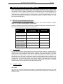
GEO S12 is rated for very high power handling and has a 16 Ohms nominal impedance in passive
mode or 2 x 16 Ohms nominal impedance in active mode.
These high impedance values allow connection of 3 to 6 cabinets in parallel for each amplifier channel.
Nexo recommends amplifiers in agreement with table below:
Recommended
Amplifier#
Channel 1
Channel 2
LF in Active Mode or
HF in Active Mode
LF+HF in Passive Mode
GEO S12 Passive Mode
1750 to 3100 W / 4 Ohms
3 in parallel (5.3 Ohms load)
GEO S12 Active Mode
1750 to 3100 W / 4 Ohms
875to 1550 W / 4 Ohms
2000 W to 3600 W / 4 Ohms
-
2000 to 3600 W / 4 Ohms
1000 to 1800 W / 4 Ohms
3 in parallel (5.3 Ohms load)
GEO S12 Passive Mode
4 in parallel (4 Ohms load)
GEO S12 Active Mode
4 in parallel (4 Ohms load)
GEO S12 Passive Mode
3300 to 6000 W / 2 Ohms
6 in parallel (2.7 Ohms load)
GEO S12 Active Mode
3300 to 6000 W / 2 Ohms
1650 to 3000 W / 2 Ohms
6 in parallel (2.7 Ohms load)
3.1.1
Current rating
It is very important that the amplifier behaves correctly under low load conditions. A speaker system is
reactive by nature: on transient signals like music it will require four to ten times more instantaneous
current than its nominal impedance would indicate. Amplifiers are generally specified by continuous
RMS power into resistive loads, however the only useful information about current capacity is the
specification into a 2 Ohm load. It is possible to perform an amplifier listening test by loading the amps
with twice the number of cabinets considered for the application (2 speakers per channel instead of one,
4 instead of 2) and running the amps up to the onset of clipping. If the signal does not noticeably
deteriorate, the amplifier is well adapted (overheating after approximately ten minutes is normal but
thermal protection must not operate too quickly after starting this test).
3.1.2
Amplifier settings
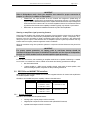
Gain value
Gain is the key to correct alignment of the system. It is especially important to know the gain of all
amplifiers used in your set-up. The tolerance should be about ±0.5 dB. In practice this can be difficult to
achieve because:
Page 16/113
AMPLIFIER SELECTION FOR USE WITH GEO S12S
•
Some amplifier brands have an identical input sensitivity for models of different power rating (this
infers a different voltage gain for each model). For example, a range of amplifiers with different
power outputs, all having a published input sensitivity of 775mV/0dBm or 1.55V/+6dBm, will have
a wide range of actual gains – the higher the power, the greater the gain.
•
Various other brands may offer constant gain but only within a given product range, for example
they may fit fixed input sensitivity only on their semi-professional amps.
•
Even if a manufacturer applies the constant gain rule to all models, the value selected will not
necessarily be the same as that chosen by other manufacturers.
•
Some products can exhibit manufacturing tolerances for the same model of ±1dB or more. Some
amplifiers may have been modified, possibly without any label indicating the new values. Others
may have gain switches fitted internally where it is impossible for the user to verify the actual
setting without opening the amplifier casing.
•
In cases where you don't know the gain of your amplifier (or want to check it) please follow this
procedure:
1) Unplug any loudspeakers from the amplifier outputs
2) With a signal generator, feed a sine wave at 1000Hz at a known voltage (say 0.5V) to
the input of the amplifier under test
3) Measure the voltage at the output of the amplifier
4) Calculate the gain using the formula Gain = 20 * LOG10(Vout/Vin).
Some examples:
Vin / Gain
0.1 V
20dB
1V
26dB
2V
32dB
4V
37dB (1.4V sensitivity / 1350Wrms)
7.1 V
0.5 V
5V
10 V
20 V
35.4 V
1V
10 V
20 V
40 V
70.8 V
Remember that constant sensitivity settings will give a different gain value when the amplifier power is
different.
NEXO recommends low gain amplifiers: +26dB is recommended, as it is at the same time adequately
low and quite common amongst amplifier manufacturers. This gain setting improves signal to noise ratio
and allows all preceding electronic equipment, including the NX242 TDcontroller or GEO S12
TDController, to operate at optimum level. Remember that using a high gain amplifier will raise the
noise floor proportionally.
Operating Mode
Most two channel amplifiers available on the pro-audio market have the following operating modes:
•
Stereo: two fully independent channels deliver identical power into identical loads
•
NEXO recommends Stereo Mode for all amplifier channels feeding GEO S12’s.
•
Bridge-Mono: the second signal channel processes the same input as the first channel, but with
reversed phase. The (single) load is connected between the two positive channel outputs using a
suitable connection. While the total output of the amplifier remains the same, the available output
voltage, the minimum impedance that can be connected and the voltage gain are doubled as
compared with stereo operation. Typically, only channel 1 input is active. Positive and negative
output connections vary depending on amplifier manufacturers.
•
NEXO does not recommend Bridge Mono Mode unless amplifier power is clearly not sufficient.
AMPLIFIER SELECTION FOR USE WITH GEO S12S
Page 17/113
IMPORTANT
When in Bridge-Mono mode, check your amplifier user manual for proper connection of
outputs 1(+) and (2+) in relation to input phase.
•
Parallel-mono: the output terminals of the two channels are configured in parallel using an
internal relay. The (single) load is connected either to the output of channel 1 or to that of channel
2 (as if in stereo). While the total output of the amplifier remains the same the output voltage level
is also the same as in stereo mode. The minimum impedance that can be connected is reduced
by half due to the fact that current capability is doubled. Typically, only channel 1 input is active.
•
NEXO does not recommend Parallel-Mono Mode for any GEO S12 amplification.
Warning on amplifiers signal processing features
Some high-end amplifiers may include signal processing functions similar to those found in the NX242
TDcontroller or in GEO S12 TDController ("loudspeaker offset integration", "limiter", "compressor," etc.).
Moreover, when this processing is digital, computation latency time can introduce a few milliseconds
delay from input to output. These functions are not adapted to specific system requirements and may
interfere with the complex protection algorithms used in the NX242.
NEXO do not advise using other protection systems in conjunction with the NX242 and they should be
disabled.
IMPORTANT
For proper system protection, no latency time or non-linear devices should be
introduced between the output of the NX242 TDcontroller and the input of loudspeakers
through use of DSP modules such as internal amplifier signal processing.
3.1.3
Example
For a 6 GEO S12 cluster, and considering an amplifier model which is capable of delivering 2 x 3300W
into 2 Ohms or 2 x 2300W into 4 Ohms, NEXO recommends the following quantities and settings:
3.2
•
Geo S12 Passive Mode:
•
1 stereo amplifier, 3 x GEO S12 per amplifier channel, mode switch in Stereo position, Gain
switch in 26 dB gain position, all dynamic or filter processing switches off.
GEO S12s and NXAMP TDControllers
NEXO Powered TDControllers NXAMP 4X1 & 4X4 are integrated solutions for Control and amplification
for all NEXO speaker ranges.
NXAMP4x1 and NXAMP4x4 power capability is listed in the table below:
Mode
NXAMP4x1
4 Channels
Bridge Stereo
4 x 600 Watts / 8 Ohms
2 x 1800 Watts / 8 Ohms
4 x 900 Watts / 4 Ohms
2 x 2600 Watts / 4 Ohms
4 x 1300 Watts / 2 Ohms
NXAMP4x4
4 x 1900 Watts / 8 Ohms
2 x 6600 Watts / 8 Ohms
4 x 3300 Watts / 4 Ohms
2 x 8000 Watts / 4 Ohms
4 x 4000 Watts / 2 Ohms
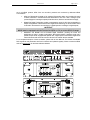
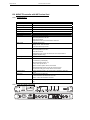
3.2.1
NXAMP connectors
NXAMP4x1 and NXAMP4x4 rear panels feature:
•
4 analog inputs / outputs (links) on XLR3 connectors;
•
4 digital inputs / outputs on RJ45 connectors with optional NX-ES104 card;
•
4 speaker level outputs on NL4FC connectors.
Page 18/113
AMPLIFIER SELECTION FOR USE WITH GEO S12S
Figure below shows connectors implementation on the rear panel.
3.2.2
GEO S12s and NXAMP recommended configurations
3 GEO S12
4 GEO S12
Passive Mode
Active Mode
1 channel of NXAMP4x1 in Bridge Stereo Mode
2 channels of NXAMP4x1 in Bridge Stereo Mode
1 channel of NXAMP4x4 in 4 channels mode
2 channels of NXAMP4x4 in 4 channels mode
1 channel of NXAMP4x4 in 4 channels mode
2 channels of NXAMP4x4 in 4 channels mode
GEO S12 SETUPS ON NEXO TD CONTROLLERS
4
4.1
Page 19/113
GEO S12 SETUPS ON NEXO TD CONTROLLERS
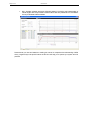
Digital NX242-ES4 and NXAMP TDControllers
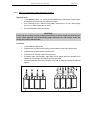
At GEO S12 release time, 38 setups combining GEO S12s with NEXO subwoofers are available in
NX242 / NXAMP load 2.45. Please consult www.nexo-sa.com for upgrade releases.
GEO S12
- 4 x S1210 Passive Wideband;
- 4 x S1230 Passive Wideband;
- 2 x S1210 Active Wideband;
- 2 x S1230 Active Wideband;
- 2 x S1210 Active X-Over 80 Hz;
- 2 x S1230 Active X-Over 80 Hz;
GEO S12
- 2 x S1210 Passive Wideband + 2 x Alpha S2;
& ALPHA S2
- 2 x S1230 Passive Wideband + 2 x Alpha S2;
- 2 x S1210 Passive X-Over 80 Hz + 2 x Alpha S2;
- 2 x S1230 Passive X-Over 80 Hz + 2 x Alpha S2;
GEO S12
- 2 x S1210 Passive Wideband + 1 x GeoSub 35 Hz – 80 Hz;
& GEO SUB
- 2 x S1230 Passive Wideband + 1 x GeoSub 35 Hz – 80 Hz;
- 2 x S1210 Passive Wideband + 1 x GeoSub 35 Hz – 200 Hz;
- 2 x S1230 Passive Wideband + 1 x GeoSub 35 Hz – 200 Hz;
- 2 x S1210 Passive X-Over 80 Hz + 1 x GeoSub 35 Hz – 80 Hz;
- 2 x S1230 Passive X-Over 80 Hz + 1 x GeoSub 35 Hz – 80 Hz;
- 2 x S1210 Passive X-Over 80 Hz + 1 x GeoSub 35 Hz – 200 Hz;
- 2 x S1230 Passive X-Over 80 Hz + 1 x GeoSub 35 Hz – 200 Hz;
- 2 x S1210 Active X-Over 80 Hz + 1 x GeoSub 35 Hz – 80 Hz;
- 2 x S1230 Active X-Over 80 Hz + 1 x GeoSub 35 Hz – 80 Hz;
- 2 x S1210 Active X-Over 80 Hz + 1 x GeoSub 35 Hz – 200 Hz;
- 2 x S1230 Active X-Over 80 Hz + 1 x GeoSub 35 Hz – 200 Hz;
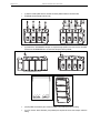
GEO S12
- 2 x S1210 Passive Wideband + 1 x CD18 85Hz;
& CD18
- 2 x S1230 Passive Wideband + 1 x CD18 85 Hz;
- 2 x S1210 Passive X-Over + 1 x CD18 85 Hz;
- 2 x S1230 Passive X-Over + 1 x CD18 85 Hz;
- 2 x S1210 Active X-Over + 1 x CD18 85 Hz;
- 2 x S1230 Active X-Over + 1 x CD18 85 Hz;
GEO S12
- 2 RS15 omni 35Hz-80Hz + 2 x S1210 Passive Wideband
& RS15
- 2 RS15 omni 35Hz-80Hz + 2 x S1230 Passive Wideband
- 1 x RS15 cardio 35Hz-80Hz + 1 x S1210 Active Wideband
- 1 x RS15 cardio 35Hz-80Hz + 1 x S1230 Active Wideband
- 2 RS15 omni 35Hz-80Hz + 2 x S1210 Passive X-Over
- 2 RS15 omni 35Hz-80Hz + 2 x S1230 Passive X-Over
- 1 x RS15 cardio 35Hz-80Hz + 2 x S1210 Passive X-Over
- 1 x RS15 cardio 35Hz-80Hz + 2 x S1230 Passive X-Over
- 1 x RS15 cardio 35Hz-80Hz + 1 x S1210 Active X-Over
- 1 x RS15 cardio 35Hz-80Hz + 1 x S1230 Active X-Over
Page 20/113
4.2
CONNECTION DIAGRAMS
Analogue GEOS12 TDController
GEO S12 TDController parameters have been optimized for 1 x RS15 (omni mode, mono) used in
conjunction with 2 x GEO S1210’s or 2 Geo x S1230’s (mono or stereo).
5
5.1
CONNECTION DIAGRAMS
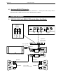
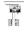
GEO S12 & RS15 with GEOS12 TDController (Mono Omni Mode)
FROM AMPLIFIERS
CAUTION !
Sense must be connected for
speaker protection
SEE USER MANUAL
TO AMPLIFIERS
BALANC ED IN PUT S
BALANC ED OUT PUT S
SEN SE IN PUT
EARTH
LIFT
OUT PUT
LEVEL
LEFT
0dB
-12dB
-6dB
GEOS12
LEFT
RIGHT
SUB
OUT
SUB L+R
GEOS12
RIGHT
(from amp terminals)
GEOS12
LEFT
GEOS12
RIGHT
SUB
+ 3- + 2 - + 1 -
Speakon 4
1 (+) / 1 (-) VLF
2 (+) / 2 (-) N.C.
1 (+) / 1 (-) VLF1 *
2 (+) / 2 (-) VLF2 *
Speakon 4
MONO
AMPLIFIER 1
* VLF1 and VLF2 on one amplifier channel
STEREO
AMPLIFIER 2
Speakon 4
Speakon 4
Speakon 4
1 (+) / 1 (-) N.C.
2 (+) / 2 (-) FULL RANGE
Speakon 4
RIGHT
STEREO
IN
LEFT
CONNECTION DIAGRAMS
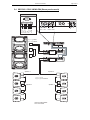
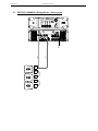
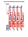
GEO S12 / NX242-ES4 (4 channels passive mode)
FROM AMPLIFIERS
TO AMPLIFIERS
IN
2
GEOS12 GEOS12 GEOS12 GEOS12
#4
#2
#3
#1
GEOS12
#1
GEOS12
#2
GEOS12
#3
+ 4 - + 3- + 2 - + 1 GEOS12
#4
5.2
Page 21/113
Speakon 4
Speakon 4
STEREO
Speakon 4
AMPLIFIER 1
STEREO
AMPLIFIER 2
Speakon 4
Speakon 4
Speakon 4
1 (+) / 1 (-) N.C.
2 (+) / 2 (-) FULL RANGE
Speakon 4
Speakon 4
GEOS12
4 CHANNELS
IN
1
Page 22/113
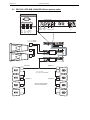
GEO S12 / ALPHA S2 / NX242-ES4 (Stereo passive mode)
FROM AMPLIFIERS
TO AMPLIFIERS
GEOS12 GEOS12 SUB
RIGHT
RIGHT LEFT
SUB
LEFT
STEREO
IN
SUB
RIGHT
SUB
LEFT
GEOS12
LEFT
+ 4 - + 3- + 2 - + 1 GEOS12
RIGHT
5.3
CONNECTION DIAGRAMS
Speakon 4
Speakon 4
1 (+) / 1 (-) VLF
2 (+) / 2 (-) N.C.
1 (+) / 1 (-) VLF
2 (+) / 2 (-) N.C.
STEREO
AMPLIFIER 1
STEREO
AMPLIFIER 2
Speakon 4
Speakon 4
1 (+) / 1 (-) N.C.
2 (+) / 2 (-) FULL RANGE
Speakon 4
Speakon 4
GEOS12 STEREO MODE
WITH S2 SUB STEREO
CONNECTION DIAGRAMS
GEO S12 / CD18 / NX242-ES4 (Stereo passive mode)
FROM AMPLIFIERS
TO AMPLIFIERS
SUB
GEOS12 GEOS12 SUB
FRONT REAR
RIGHT LEFT
SUB
FRONT
SUB
REAR
GEOS12
LEFT
+ 4 - + 3- + 2 - + 1 GEOS12
RIGHT
5.4
Page 23/113
1 (+) / 1 (-) REAR
2 (+) / 2 (-) FRONT
Speakon 4
STEREO
AMPLIFIER 1
STEREO
AMPLIFIER 2
Speakon 4
Speakon 4
1 (+) / 1 (-) N.C.
2 (+) / 2 (-) FULL RANGE
Speakon 4
Speakon 4
GEOS12 STEREO MODE
WITH CD18 MONO
STEREO
IN
Page 24/113
GEO S12 / GEO SUB / NX242-ES4 (Stereo passive mode)
FROM AMPLIFIERS
TO AMPLIFIERS
SUB
GEOS12 GEOS12 SUB
FRONT REAR
RIGHT LEFT
SUB
FRONT
SUB
REAR
GEOS12
LEFT
+ 4 - + 3- + 2 - + 1 GEOS12
RIGHT
5.5
CONNECTION DIAGRAMS
1 (+) / 1 (-) REAR
2 (+) / 2 (-) FRONT
Speakon 4
STEREO
AMPLIFIER 1
STEREO
AMPLIFIER 2
Speakon 4
Speakon 4
1 (+) / 1 (-) N.C.
2 (+) / 2 (-) FULL RANGE
Speakon 4
Speakon 4
GEOS12 STEREO MODE
WITH GEO SUB MONO
STEREO
IN
CONNECTION DIAGRAMS
SP4
SP4
SP4
SP4
SP4
SP4
SP4
SP4
SP4
SP4
IN A
IN B
OUT A
GEO S12 / NXAMP4x1 (Bridge Stereo - Passive mode)
OUT D
5.6
Page 25/113
Page 26/113
SP4
SP4
SP4
SP4
SP4
4 x LF
IN A
OUT A
OUT D
GEO S12 / NXAMP4x1 (Bridge Stereo - Active mode)
4 x HF
5.7
CONNECTION DIAGRAMS
CONNECTION DIAGRAMS
IN A
IN B
IN C
IN D
OUT A
OUT B
OUT C
GEO S12 / NXAMP4x4 (4 Channels - Passive mode)
OUT D
5.8
Page 27/113
SP4
SP4
SP4
SP4
SP4
SP4
SP4
SP4
SP4
SP4
SP4
SP4
SP4
SP4
SP4
SP4
SP4
SP4
SP4
SP4
SP4
SP4
SP4
SP4
SP4
SP4
SP4
SP4
Page 28/113
4 x HF
4 x LF
4 x LF
SP4
SP4
SP4
SP4
SP4
SP4
SP4
SP4
SP4
SP4
SP4
SP4
SP4
SP4
IN A
IN B
OUT A
OUT B
OUT C
OUT D
GEO S12 / NXAMP4x4 (Stereo Active mode)
4 x HF
5.9
CONNECTION DIAGRAMS
NS-1 SIMULATION SOFTWARE
6
Page 29/113
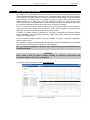
NS-1 SIMULATION SOFTWARE
NS-1 software is a R&D simulation tool derived application. It processes measured speaker data with
complex mathematical algorithms to assist the user in optimizing system design. Due to the complexity
of the interaction of multiple cabinets, it is simply not possible to reliably design curved vertical arrays
without using the processing power of a computer to predict the optimum array structure for a given
audience geometry. The design logic is far more complex than looking at a section drawing of the
venue, measuring the overall angle needed to cover the audience from the cluster location, and dividing
by 10 degrees to determine the required amount number of GEO S1210 cabinets.
NS-1 is an easy to use tool that allows to shape the energy leaving the cluster to fit the audience. It
predicts pressure levels radiated from the system to ensure enough cabinets are provided for the
application, as well as mechanical constraints for safe flown systems.
In addition, it provides mechanical information for all clusters in agreement with Structural Analysis
Reports (available in the Help section): dimensions, weight, gravity center position, forces, moments,
working load and safety factor.
Geo S12 Structural Analysis Reports have been validated by German Certification Organization
RWTUV systems GmbH.
NS-1 installation package includes all NEXO User Manuals, Structural Analysis Reports and Certificates
PDF files (which can be found in the last section of User Manuals).
NS-1 is a freeware available for all Nexo users. Please contact your local distributor for
licensing procedure.
IMPORTANT
Never install a GEO S12 cluster without checking its acoustical performances and
mechanical safety in NS-1 prior to installation.
Any question or bug report please contact [email protected]
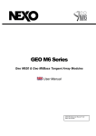
NS-1 GEO S12 ACOUSTIC PAGE
Page 30/113
7
CONFIGURABLE DIRECTIVITY DEVICE
CONFIGURABLE DIRECTIVITY DEVICE
The GEO Wavesource controls dispersion of acoustic energy using an hyperboloid acoustical reflector
in the “coupling plane” (the vertical plane of a curved vertical tangent array) and a diffraction slot in the
“non-coupling plane” (the horizontal plane of a curved vertical tangent array). The patented
Configurable Directivity Device consists of bolt-on flanges that alter the diffraction slot’s exit flare rate.
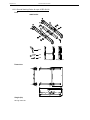
7.1
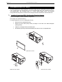
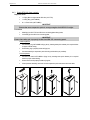
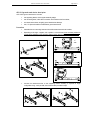
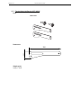
Installing & removing GEO’s Configurable Directivity flanges
GEO S12 are shipped in the 80° dispersion configuration;
120° flanges is an optional accessory.
To change dispersion in the non-coupling plane to 120°:
•
Remove the front grill (drawings below);
•
Remove the three TORX (5x25) screws per flange on each side of the GEO Waveguide
(drawings below);
•
Install the 120° flanges with the six TORX screws
•
Re-install the grid, being careful that the NEXO logo must be on the 12” loudspeaker side.
REMOVING THE GRILL
REMOVING THE SCREWS
REPLACING THE FLANGES
CONFIGURABLE DIRECTIVITY DEVICE
7.2
Page 31/113
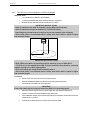
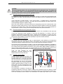
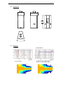
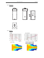
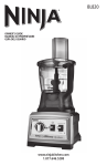
When & where to use Configurable Directivity flanges
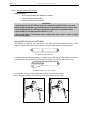
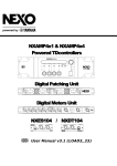
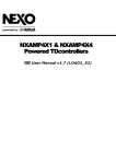
The diagrams show audience area coverage for a stereo system. While the GEO cluster will deliver
even SPL from the front to the rear of this audience area, there are “holes” near the front in the centre
and at the outside edges. We cannot fill the outside coverage gaps without enlarging the centre gap,
and vice versa (left figure below).
If 120° Configurable Directivity Devices are installed at the bottom cabinet of the clusters, coverage will
look more like the pattern in right figure below.
-6dB coverage, all GEO S12 in 80° configuration
-6dB coverage, bottom GEO S12 in 120° configuration
In curved vertical arrays, the 120° Configurable Directivity Device can be used:
•
On the bottom row of curved vertical arrays, to fill in coverage gaps in the front rows.
•
On all rows of curved vertical arrays, in cases where 120° of horizontal coverage is
preferred to 80°.
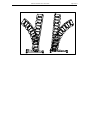
Figure below shows isocontour coverage for 80° and 120° configurations.
80° AND 120° CONFIGURATIONS ISOCONTOUR COVERAGE
Page 32/113
8
GEO S12 HARDWARE SETUP PROCEDURE
GEO S12 HARDWARE SETUP PROCEDURE
Before proceeding with assembly of GEO S12 arrays, please ensure that the components are present
and undamaged. A component list is appended to this manual. In the event of any shortage, please
contact your supplier.
For maximum efficiency the GEO S12 rigging system requires three experienced persons for set-up:
typically one motor hoist operator, and one GEO S12 operator per side of the array. Good
synchronisation and crosscheck between the operators are key elements for a reliable and safe set-up.
8.1
SAFETY FIRST
GEO S12 Rigging System structural computations and related documents are available in Geosoft2 or
at Nexo ([email protected]) upon request.
We include this section to remind you of safe practice when flying the GEO S12 system. Please read it
carefully. However, user must always apply his or her knowledge, experience and common sense. If in
any doubt, seek advice from your supplier or NEXO agent.
This manual offers guidance only for GEO S12 loudspeaker systems. References in this manual to
other rigging equipment such as motor hoists, steels, shackles etc. are made to clarify the description of
GEO S12 procedures. The user must ensure that operators are properly trained by other agencies in
the use of these items.
The GEO S12 Rigging System has been optimised for the deployment of curved vertical or horizontal
tangent arrays of GEO S12 loudspeakers. Angle adjustment between cabinets has been limited to
specific settings to ensure correct acoustic coupling.
The GEO S12 Rigging System is a professional precision tool set, and should be handled with extreme
care. Only persons who are fully conversant with the operation of the GEO S12 Rigging System and
provided with suitable safety equipment should deploy GEO Arrays. Misuse of the GEO S12 Rigging
System could lead to dangerous consequences.
Used and maintained correctly, the GEO S12 Rigging System will give many years of reliable service in
portable systems. Please take the time to read and understand this manual. Always use GEOSoft2 to
determine the optimum angle settings for a particular venue, hang point and curved vertical GEO S12
cluster. Applied forces and moments are strongly cabinet quantity and angle configuration dependent.
Cluster configuration must be implemented and validated in Geosoft2 prior to installation.
8.1.1
Flown Systems Safety
•
Always inspect all the rigging components and cabinets for damage before assembly. Pay
special attention to the lifting points, and safety clips. If you suspect that any of the components
are damaged or defective, DO NOT USE THE AFFECTED PARTS. Contact your supplier for
replacements.
•
Read this manual carefully. Also be familiar with the manuals and safe working procedures for
any ancillary equipment that will be used with the GEO S12 Rigging System.
•
Applied forces and moments are strongly cabinet quantity and angle configuration dependent.
Cluster configuration must be implemented and validated in Geosoft2 prior to installation.
•
Ensure that all local and National regulations regarding the safety and operation of flying
equipment are understood and adhered to. Information on these regulations can usually be
obtained from Local Government Offices.
•
When deploying a GEO S12 system always wear protective headwear, footwear and eye
protection.
•
Do not allow inexperienced persons to handle a GEO S12 system. Installation personnel should
be trained in loudspeaker flying techniques and should be fully conversant with this manual.
•
Ensure that motor hoists, hoist control systems and ancillary rigging components are currently
certified as safe and that they pass a visual inspection prior to use.
GEO S12 HARDWARE SETUP PROCEDURE
8.1.2
Page 33/113
•
Ensure that public and personnel are not allowed to pass beneath the system during the
installation process. The work area should be isolated from public access.
•
Never leave the system unattended during the installation process.
•
Do not place any object, no matter how small or light, on top of the system during the installation
procedure. The object may fall when the system is flown and is likely to cause injury.
•
Secondary safety steels must be installed once the system has been flown to the operating
height. Secondary steels must be fitted irrespective of requirements of the local safety standards
applicable to the territory.
•
Ensure that the system is secure and prevented from pivoting around the motor hoist.
•
Avoid any form of excessive dynamic loading to the assembly (structural computations on GEO
S12 Rigging System are based on a 1/1.2 factor for hoist or motor acceleration).
•
NEVER attach any item to the GEO S12 system other than the GEO S12 accessories.
•
When flying outdoor systems ensure that the system is not exposed to excessive wind or snow
loads and is protected from rainfall.
•
The GEO S12 Rigging System requires regular inspection and testing by a competent test
centre. NEXO recommend that the system is load tested and certified annually or more
frequently if local regulations require.
•
When de-rigging the system ensure that the same duty of care is given to the procedure as for
the installation. Pack GEO S12 components carefully to prevent damage in transit.
Ground Stacking Safety
Statistically, many more injuries occur due to unstable ground stacked PA systems than those
associated with flown systems. There are several reasons for this fact, however the message is clear:
•
Always survey the supporting structure upon which a ground stack is to be built. Always look
beneath PA wings to inspect the deck support and if necessary ask for the stage scrims and
dressings be removed to allow access.
•
If the stage surface slopes, as it does in some theatres, ensure that the system is prevented from
sliding forwards due to vibration. This may require the fitting of timber battens to the stage floor.
•
For outdoor systems ensure that that the system is protected from wind forces which might
cause the ground stack to become unstable. Wind forces can be huge, especially upon large
systems, and should never be underestimated. Observe meteorological forecasts, calculate the
“worst case” effect upon the system prior to erection and ensure that the system is secured
appropriately.
•
Take care when stacking cabinets. Always employ safe lifting procedures and never attempt to
build stacks without sufficient personnel and equipment.
•
Never allow anyone, whether operators, artists or members of the public to climb onto a ground
stacked PA system. Anyone who needs to climb over 2m (6 ft) high should be fitted with suitable
safely equipment including a clip-on harness. Please refer to local Health and Safety legislation in
your territory. Your dealer can help with advice on access to this information.
•
Apply the same attention to all safety matters when de-stacking systems.
•
Be aware that safety procedures are as important in the truck and in the warehouse as they are
at the venue.
Page 34/113
8.1.3
GEO S12 HARDWARE SETUP PROCEDURE
Contacts
Correct training is fundamental to safe practise when working with loudspeakers flying systems. NEXO
recommend that users contact local industry associations for information on specialist course.
Information for International training agencies can be obtained by contacting either:
The Production Services Association
(PSA),
School Passage,
Kingston-upon-Thames,
KT1 SDU Surrey,
ENGLAND
Telephone: +44 (0) 181 392 0180
Rigstar Training and Testing Center
82 Industrial Dr. Unit 4
Northampton, Massachusetts 01060 U.S.A.
Phone: 413-585-9869 -- Fax: 413-585-9872
[email protected]
ESTA
Entertainment Services & Technology Association
875 Sixth Avenue, Suite 1005
NEW YORK, NY 10001 USA
Phone: 212-244-1505 – Fax: 212-244-1502
[email protected] - www.esta.org
GEO S12 HARDWARE SETUP PROCEDURE
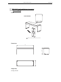
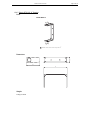
8.2
Page 35/113
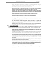
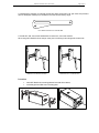
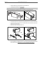
General Description
GEO S1230
GEO S1210
GEO S1230 and GEO S1210 incorporate two connecting plates (one per side) on which a
comprehensive range of accessories can be mounted.
Oblong holes for Touring Applications Accessories
Tapped holes for Fixed Installation Accessories
GEO S12 CONNECTING PLATES
There are two families of accessories:
•
fixed installation accessories, which are designed to be screwed on the connecting plates;
•
touring accessories, which can be installed or removed with a quick connecting system.
Page 36/113
8.2.1
GEO S12 HARDWARE SETUP PROCEDURE
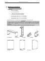
Described configurations
SECTION 8.3.4
SECTION 8.3.2
SECTION 8.3.3
SECTION 8.3.2
SECTION 8.3.6
FIXED INSTALLATIONS
SECTION 8.4.3
SECTION 8.4.7
SECTION 8.4.6
SECTION 8.4.4
SECTION 8.4.9
SECTION 8.4.5
SECTION 8.4.2
SECTION 8.4.8
TOURING APPLICATIONS
GEO S12 HARDWARE SETUP PROCEDURE
8.2.2
Page 37/113
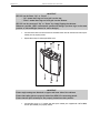
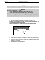
WARNINGS ON GEO S12 ACCESSORIES
WARNING 1T
All GEO S12 Accessories are specifically rated in agreement with structural
computations.
Never use other accessories – including push-pins - when assembling GEO S12 cabinets
than the ones provided by NEXO: NEXO will decline responsibility over the entire GEO
S12 accessory range if any component is purchased from different supplier.
WARNING 2
For SAFETY reasons, following first generation accessories:
- GEOS12-XBOW
- GEOS12-TCBRK
- GEOS12-SSBRK
- GEOS12-PSBRK
- GEOS12-TTC
Have been recalled in August 2007 and MUST NO LONGER BE USED
These accessories have been replaced by:
- GEOS12-XBOW-V2
- GEOS12-TCBRK-V2
- GEOS12-SSBRK-V2
- GEOS12-PSBRK-V2
- GEOS12-TTC-V2
Please contact your local distributor if any doubt in relation the GEO S12 accessories you
are using.
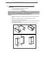
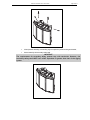
WARNING 3
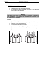
All GEO S12 accessories have been designed so that cabinets are arrayed in the acoustic
coupling plane (adjacent waveguides as shown in figures below).
GEO S12 assemblies in the “non coupling plane” – as shown in figure below- are UNSAFE
and STRICTLY PROHIBITED.
YES
YES
NO
Page 38/113
8.3
GEO S12 HARDWARE SETUP PROCEDURE
GEO S12 in fixed installations
8.3.1
Fixed installation Accessories and kits
Accessories are:
•
Bumper (GPI-BUMPER)
•
“U” Bracket (VNI-UBRK12)
•
“L” Bracket for cable suspension (VNI-LBRK)
•
“U” Bracket for rigid suspension (VNI-ABRK)
•
Connecting Plates / range : 0.20° - 3.15° (GPI-ANPL1)
•
Connecting Plates / range : 5.00° - 10.0° (GPI-ANPL2)
•
Connecting Plates / range : 16.0° - 30.0° (GPI-ANPL3)
Please refer to section 13.4 of this manual for more information of above references.
IMPORTANT
In order to prevent screws from getting loose in fixed installations, use blocking liquid
LOCTITETM 243 or equivalent for all screws used with GEO S12 fixed installation
accessories.
LOCTITETM 243 is available at NEXO or at your local distributor upon request.
GPI-BUMPER
GPI-ANPL1
VNI-UBRK12
VNI-LBRK
GPI-ANPL2
VNI-ABRK
GPI-ANPL3
GEO S12 HARDWARE SETUP PROCEDURE
8.3.2
Page 39/113
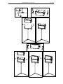
Single GEO S12 rigidly mounted on a wall or a ceiling (vertical or horizontal)
Required items
•
1 x GEOS12-UBRK (allows all angles to be implemented)
•
4 x 12mm diameter screws (not provided)
IMPORTANT
Ensure that the surface – wall or ceiling – is strong enough to hold GEO S12 weight and
that the for screws 12mm diameter and corresponding plugs required to fix the “U”
bracket on the wall or under the ceiling are properly dimensioned.
Procedure
•
For screws 12mm diameter (not provided) are required to secure the “U” Bracket on the wall or
ceiling;
•
Remove the four TORX screws holding connector plates on both sides of GEO S12;
•
Fill each screw hole with Locktite 243 or equivalent;
•
Position the GEO S12 inside the “U” Bracket to desired angle; “U” bracket oblong holes must be
properly aligned with panels holes;
•
Use the eight screws and washers from VNI-UBRK12 kit to connect “U” bracket to cabinet.
Page 40/113
8.3.3
GEO S12 HARDWARE SETUP PROCEDURE
Single GEO S12 cable mounted on a wall or a ceiling (vertical or horizontal)
Required items
•
1 or 2 x VNI-LBRK (allows cable suspension, holes for cable suspension are 10mm diameter);
•
2 or 4 slings and corresponding shackles (not provided)
IMPORTANT
Ensure that the ceiling is strong enough to hold GEO S12 weight and that the cable
suspension system required to install the cabinet under the ceiling is properly
dimensioned.
Procedure
Vertical
•
Remove the four TORX screws holding connector
plate on upper side of GEO S12;
•
Remove the connector plate from Geo S12;
•
Fill each screw hole with Locktite 243 or equivalent;
•
Position external plate from VNI-LBRK kit and secure
it using the 2 of the 4 shoulder screws supplied with
this kit;
•
Position “L” bracket from VNI-LBRK kit, and secure it
to the cabinet using the 2 remaining shoulder screws
supplied with this kit.
•
Slings and shackles (not provided) are required to
secure the cluster under the ceiling;
Horizontal
•
Remove the four TORX screws holding connector
plates on both side of GEO S12;
•
Remove the connector plates from Geo S12;
•
Fill each screw hole with Locktite 243 or equivalent;
•
Position external plates from VNI-LBRK kits and
secure them using the shoulder screws supplied with
these kits;
•
Position “L” brackets from VNI-LBRK kits, and secure
them to the cabinet using the 4 remaining shoulder
screws supplied with these kits.
•
Slings and shackles (not provided) are required to
secure the cluster under the ceiling;
GEO S12 HARDWARE SETUP PROCEDURE
8.3.4
Page 41/113
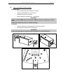
GEO S12 vertical array rigidly mounted on a ceiling
Required items
•
1 x GPI-BUMPER (allows +/-5° bumper tilt when installed below a flat surface; if higher bumper
tilt is required, surface will have to be defined accordingly) ;
•
(N-1) x GPI-ANPL for a N x GEO S12 array (ANPL1 ranges from 0.2° to 3.15°, ANPL2 ranges
from 5° to 10°, ANPL3 ranges from 16° to 30°)
•
Four 12mm diameter screws (not provided)
IMPORTANT
Ensure that the ceiling is strong enough to hold GEO S12 cluster weight and that the four
screws 12mm diameter and corresponding plugs required to fix the bumper under the
ceiling are properly dimensioned.
Procedure
•
(1) Set all GEO S12 side by side;
•
(2) Remove the four TORX screws holding connector plates on upper side of all GEO S12’s;
•
(3) Remove the connector plates from all Geo S12’s;
•
(4) Fill each screw hole with Locktite 243 or equivalent;
•
(5) Position bottom external plates, angle plates and top external plate from GPI-ANPL kit to
required inter-cabinet angle value between cabinets upper sides;
•
(6) Screw all shoulder screws from GPI-ANPL kits so that all plates and cabinets are tightened
together;
•
•
•
•
•
•
•
•
•
•
Page 42/113
GEO S12 HARDWARE SETUP PROCEDURE
•
(7) Flip the cluster upside down to access connector plates located on the down side;
•
(8) Repeat all above steps from #2 to #6;
•
•
(9) Position the GPI-BUMPER bumper to required angle position and use the four shoulder
screws from GPI-BUMPER kit to connect it the bumper to the top cabinet;
0° 1° 2° 3°4° 5°
0°
1° 2° 3°4°
5°
•
(10) Flip GEO S12 cluster by 90° so that it is ready to be positioned under the ceiling;
•
(11) Four screws 12mm diameter (not provided) are required to secure the bumper under the
ceiling.
GEO S12 HARDWARE SETUP PROCEDURE
8.3.5
Page 43/113
GEO S12 vertical array cable mounted on a ceiling
Required items
•
1 x GPI-BUMPER;
•
2 x VNI-LBRK (allows cable suspension for bumper, holes for cable suspension are 10mm
diameter);
•
(N-1) x GPI-ANPL for a N x GEO S12 array (ANPL1 ranges from 0.2° to 3.15°, ANPL2 ranges
from 5° to 10°, ANPL3 ranges from 16° to 30°)
•
4 slings and shackles (not provided)
IMPORTANT
Ensure that the ceiling is strong enough to hold GEO S12 cluster weight and that the
cables suspension system required fixing the bumper under the ceiling is properly
dimensioned.
Procedure
•
Connect the bumper and the two “L” brackets using the screws, washers and bolts provided in
the VNI-LBRK kit;
•
Proceed as in preceding section;
•
4 slings and 4 shackle (not provided) are required to secure the cluster under the ceiling;
Page 44/113
8.3.6
GEO S12 HARDWARE SETUP PROCEDURE
GEO S12 horizontal array rigidly mounted on a ceiling
Required items
•
2 x VNI-ABRK (allows rigid ceiling suspension for horizontal arrays)
•
(N-1) x GPI-ANPL for a N x GEO S12 array (ANPL1 ranges from 0.2° to 3.15°, ANPL2 ranges
from 5° to 10°, ANPL3 ranges from 16° to 30°)
•
Four 12mm diameter screws (not provided)
IMPORTANT
Ensure that the ceiling is strong enough to hold GEO S12 cluster weight and that the four
screws 12mm diameter and corresponding plugs required to fix the “L” brackets under
the ceiling are properly dimensioned.
Procedure
•
(1) Set all GEO S12 side by side;
•
(2) Remove the four TORX screws holding connector plates on upper side of all GEO S12’s;
•
(3) Remove the connector plates from all Geo S12’s;
•
(4) Fill each screw hole with Locktite 243 or equivalent;
•
(5) Position bottom external plates, angle plates and top external plate from GPI-ANPL kit to
required inter-cabinet angle value between cabinets upper sides;
•
(6) Screw all shoulder screws from GPI-ANPL kits so that all plates and cabinets are tightened
together;
GEO S12 HARDWARE SETUP PROCEDURE
Page 45/113
•
(7) Flip the cluster upside down to access connector plates located on the down side;
•
(8) Repeat all above steps from #2 to #6;
•
(9) Position the two “U” brackets from VNI-ABRK kits on the outer cabinets next the angle plates,
and tight them to the cabinets using the shoulder screws provided with these kits,
•
(10) Four screws 12mm diameter (not provided) are required to secure the “U” brackets under
the ceiling;
Page 46/113
8.3.7
GEO S12 HARDWARE SETUP PROCEDURE
GEO S12 horizontal array cable mounted on a ceiling
Required items
•
2 x VNI-LBRK (allows cable suspension for horizontal arrays, holes for cable suspension are
10mm diameter);
•
(N-1) x GPI-ANPL for a N x GEO S12 array (ANPL1 ranges from 0.2° to 3.15°, ANPL2 ranges
from 5° to 10°, ANPL3 ranges from 16° to 30°)
•
4 slings and 4 shackles (not provided).
IMPORTANT
Ensure that the ceiling is strong enough to hold GEO S12 cluster weight and that the
cables suspension system required fixing the cluster under the ceiling is properly
dimensioned.
Procedure
•
Proceed as in above section, VNI-LBRK being positioned on the outer cabinets instead of VNIABRK.
•
4 slings and 4 shackle (not provided) are required to secure the cluster under the ceiling;
GEO S12 HARDWARE SETUP PROCEDURE
8.4
Page 47/113
GEO S12 in touring applications
8.4.1
Touring Accessories
Accessories are :
•
Bumper (GPT-BUMPER)
•
Rigging Plates (GPT-XBOW)
•
Tension Mode Link Bars for GPT-XBOW (GPT-TLB)
•
Lifting Ring for GPT-SSBRK, GPT-PSBRK or VNT-TTC (VNT-XHBRK)
•
Truss hook for GPT-SSBRK, GPT-PSBRK or VNT-TTC (VNT-TCBRK)
•
“U” Bracket for single horizontal GEO S12 on pole stand, lifting ring or truss hook (GPT-SSBRK)
•
U” Bracket for two horizontal GEO S12 on pole stand, lifting ring or truss hook (GPT-PSBRK)
•
Flying Bar for single vertical GEO S12 (VNT-TTC)
•
Ground Stacking device for up to 6 GEOS1210 (GPT-GSTK)
Please refer to section 13.3 of this manual for more information of above references.
GPT- BUMPER
GPT-TLB
GPT-SSBRK
VNT-TTC
GPT-XBOW
VNT-XHBRK
VNT-TCBRK
GPT-PSBRK
GPT-GSTK
Page 48/113
GEO S12 HARDWARE SETUP PROCEDURE
8.4.2
Single GEO S12 on speaker stand or on RS15 horizontally
Required items
•
1 x “U” Bracket for single horizontal GEO S12 (GPT-SSBRK);
•
1 x Speaker stand diameter 35mm (K&M 213 or equivalent);
•
Or NEXO PS pole stand (VXT-PLSTD) for mounting on top of RS15
IMPORTANT (SPEAKER STAND)
- Speaker stand must be rated for assembly weight (40kg rated load min);
- Speaker stand must always be installed on a horizontal surface;
- Stand height and footprint must be defined to prevent assembly from collapsing;
- Ensure that public is not allowed within a safety area which radius is equal or higher
than assembly height.
H
R>H
IMPORTANT (RS15 POLE STAND)
- NEXO PLSTD pole stand only should be used for mounting on top of NEXO RS15
- If 2 RS15s are to be stacked below GEO S12s pole mounted, they should be connected
together through use of RS15 rigging plates;
- RS15s must always be installed on a horizontal surface;
- Ensure that public is not allowed within a safety area which radius is equal or higher
than assembly height.
Procedure
•
Slide GPT-SSBRK side plates into GEO S12 connecting plate oblong holes;
•
Lock safety pins into GEO S12 connecting plate;
IMPORTANT
Ensure that safety pins are properly locked into GEO S12 connecting panels.
•
Position “U” bracket over these side plates; align centre holes;
•
Insert adjustment handles, adjust vertical angle and tight the handles to prevent GEO S12 from
rotating around “U” bracket;
•
Lift assembly on speaker stand or on RS15 with PLSTD pole stand.
GEO S12 HARDWARE SETUP PROCEDURE
Page 49/113
Page 50/113
8.4.3
GEO S12 HARDWARE SETUP PROCEDURE
Single GEO S12 flown vertically
Required items
•
1 x Flying Bar for single vertical GEO S12 (VNT-TTC)
•
1 x Lifting Ring (VNT-XHBRK)
•
Or 1 x Truss hook (VNT-TCBRK)
IMPORTANT
Ensure that truss suspension point is strong enough to hold GEO S12 weight.
Procedure
•
Slide flying bar VNT-TTC into GEO S12 connecting plate oblong holes;
•
Lock safety pin into GEO S12 connecting plate;
IMPORTANT
Ensure that safety pin is properly locked into GEO S12 connecting panel.
Cable suspension:
•
Connect lifting ring VNT-XHBRK to flying bar by inserting 8x45 quick release pin in required holes
for proper vertical aiming;
•
Ensure lifting ring is properly locked to flying bar;
•
Connect assembly to suspension point with sling and shackle (not provided).
Truss suspension
•
Connect truss hook VNT-TCBRK to flying bar by inserting 8x45 quick release pin in required
holes for proper vertical aiming;
•
Ensure truss hook is properly locked to flying bar;
•
Lift and position assembly, lock hook on truss suspension point and secure with hook cable.
GEO S12 HARDWARE SETUP PROCEDURE
8.4.4
Page 51/113
Single GEO S12 flown horizontally
Required items
•
1 x “U” Bracket for single horizontal GEO S12 (GPT-SSBRK)
•
1 x Lifting Ring (VNT-XHBRK)
•
Or 1 x Truss hook (VNT-TCBRK)
IMPORTANT
Ensure that suspension point is strong enough to hold GEO S12 weight.
Procedure
•
Slide GPT-SSBRK side plates into GEO S12 connecting plate oblong holes;
•
Lock safety pins into GEO S12 connecting plate;
IMPORTANT
Ensure that safety pins are properly locked into GEO S12 connecting panels.
•
Position “U” bracket over these side plates; align centre holes;
•
Insert adjustment handles, adjust vertical angle and tight the handles to prevent GEO S12 from
rotating around “U” bracket;
Cable suspension:
•
Connect lifting ring VNT-XHBRK to “U” bracket by inserting 8x45 quick release pin dedicated
holes;
•
Ensure lifting ring is properly locked to “U” bracket;
•
Connect assembly to suspension point with sling and shackle (not provided).
Truss suspension
•
Connect truss hook VNT-TCBRK to “U” bracket by inserting 8x45 quick release pin in dedicated
holes;
•
Ensure truss hook is properly locked to “U” bracket;
•
Lift and position assembly, lock hook on truss suspension point and secure with hook cable.
Page 52/113
8.4.5
GEO S12 HARDWARE SETUP PROCEDURE
Two GEO S12 on wind-up stand or on RS15 horizontally
Required items
•
1 x U” Bracket for two GEO S12 (GPT-PSBRK)
•
1 x Wind Up stand diameter 35mm (Eurotruss ES160 or equivalent);
•
Or NEXO PS pole stand (PLSTD) for mounting on top of RS15
IMPORTANT (WIND UP STAND)
- Wind Up stand must be rated for assembly weight (80kg rated load min);
- Wind Up stand must always be installed on a horizontal surface;
- Stand height and footprint must be defined to prevent assembly from collapsing;
- Ensure that public is not allowed within a safety area which radius is equal or higher
than assembly height.
H
R>H
IMPORTANT (RS15 POLE STAND)
- NEXO STDPS pole stand only should be used for mounting on top of NEXO RS15
- If 2 RS15s are to be stacked below GEO S12s pole mounted, they should be connected
together through use of RS15 rigging plates;
- RS15s must always be installed on a horizontal surface;
- Ensure that public is not allowed within a safety area which radius is equal or higher
than assembly height.
Procedure
•
Set the 2 GEO S12 next to each other front grid to the floor
•
Slide GPT-PSBRK side plates into GEO S12s connecting plate oblong holes;
•
Lock safety pins into GEO S12s connecting plate;
IMPORTANT
Ensure that safety pins are properly locked into GEO S12s connecting panels.
•
Adjust inter-cabinet angle and lock to required angle value with 8x20quick release pins;
•
Position “U” bracket over these side plates; align centre holes;
•
Insert adjustment handles, adjust vertical angle and tight the handles to prevent GEO S12s from
rotating around “U” bracket;
•
Lift assembly on Wind Up stand or on RS15 with PLSTD pole stand.
GEO S12 HARDWARE SETUP PROCEDURE
Page 53/113
Page 54/113
GEO S12 HARDWARE SETUP PROCEDURE
Alternative Procedure (“Walder” procedure)
Below described procedure required 2 additional 8x20 quick release pins (BLGEOS)
•
Split the GPT-PSBRK side plates by removing screws and bolt;
•
Slide GPT-PSBRK lower half-plates into lower GEO S12 connecting plate oblong holes;
•
Lock safety pins into lower GEO S12 connecting plate;
•
Position “U” bracket over these lower half plates; align centre holes;
•
Insert adjustment handles, adjust vertical angle and tight the handles to prevent GEO S12 from
rotating around “U” bracket;
•
Lift assembly on Wind Up stand or on RS15 with PLSTD pole stand.
•
Slide GPT-PSBRK upper half-plates into upper GEO S12 connecting plate oblong holes;
•
Lock safety pins into upper GEO S12 connecting plate;
•
Lift upper GEO S12 on top of lower one, and connect them together by inserting 8x20 quick
release pins in articulation holes;
•
Adjust inter-cabinet angle and lock to required angle value with quick release pins.
IMPORTANT
Ensure that safety pins are properly locked into GEO S12 connecting panels.
GEO S12 HARDWARE SETUP PROCEDURE
Page 55/113
DOWN CABINET
UP CABINET
Page 56/113
8.4.6
GEO S12 HARDWARE SETUP PROCEDURE
Two GEO S12 flown horizontally
Required items
•
1 x “U” Bracket for two GEO S12s (GPT-PSBRK)
•
1 x Lifting Ring (VNT-XHBRK)
•
Or 1 x Truss hook (VNT-TCBRK)
IMPORTANT
Ensure that suspension point is strong enough to hold two GEO S12s weight.
Procedure
•
Slide GPT-PSBRK side plates into GEO S12s connecting plate oblong holes;
•
Lock safety pins into GEO S12s connecting plate;
IMPORTANT
Ensure that safety pins are properly locked into GEO S12s connecting panels.
•
Adjust inter-cabinet angle and lock to required angle value with 8x20 quick release pins;
•
Position “U” bracket over these side plates; align centre holes;
•
Insert adjustment handles, adjust vertical angle and tight the handles to prevent GEO S12s from
rotating around “U” bracket;
Cable suspension:
•
Connect lifting ring VNT-XHBRK to “U” bracket by inserting 8x45 quick release pin dedicated
holes;
•
Ensure lifting ring is properly locked to “U” bracket;
•
Connect assembly to suspension point with sling and shackle (not provided).
Truss suspension
•
Connect truss hook VNT-TCBRK to “U” bracket by inserting 8x45 quick release pin in dedicated
holes;
•
Ensure truss hook is properly locked to “U” bracket;
•
Lift and position assembly, lock hook on truss suspension point and secure with hook cable.
GEO S12 HARDWARE SETUP PROCEDURE
8.4.7
Page 57/113
Two or more GEO S12 flown vertically
Required items
•
N Pair of Rigging Plates (GPT-XBOW) for N cabinets;
•
1 lifting ring (VNT-XHBRK) every two GEO S12;
•
4xN Quick release pins for N cabinets;
•
Properly rated slings, shackles, hoists… (not provided)
IMPORTANT
Lifting ring VNT-XHBRK and truss hook VNT-TCBRK are rated for a maximum of 2 GEO
S12s;
Ensure that suspension points are rated accordingly.
Procedure
•
Insert GPT-XBOW into connecting plates of both sides of the cabinet;
•
Lock safety pins into GEO S12s connecting plate;
IMPORTANT
Ensure that safety pins are properly locked into GEO S12s connecting panels.
PROFESSIONAL EQUIPMENT !
Please refer to User Manual for Working
Load Limits (WLL) and Rigging
Instructions.
3.15°
2.0°
WARNING
Disregard of Rigging Instructions and/or
WLL may damage equipment and risk
personal injury or death.
0.8°
LIFT
LIFT
1.25°
CAUTION: ENSURE ALL PINS
ARE PROPERLY LOCKED
0.5°
10.0°
0.315°
16.0°
22.5°
8.0°
6.3°
5.0°
SAFETY P
TED
FIT
30.0°
MUST BE
IN
0.2°
Page 58/113
GEO S12 HARDWARE SETUP PROCEDURE
IMPORTANT
GEO S12 can be flown “Up” or “Down” :
- “Up” means Nexo logo on front grid is at the top;
- “Down” means Nexo logo on front grid is at the bottom.
GEO S12 can be connected “Up” or “Down” by simply flipping the cabinets.
Whenever possible, NEXO recommends symmetrical designs (ie Nexo logo in the same
position on Left and Right clusters for stereo designs)
•
Connect second Geo S12 with X-Bow front articulation holes and rear link bars and ensure quick
release pins are properly locked;
•
Repeat above steps for subsequent GEO S12’s;
IMPORTANT
Ensure angle settings are identical on upper and lower side of the cabinets
Ensure that safety pins are properly locked into GEO S12s connecting panels.
Ensure that all quick release pins are properly locked into their position.
•
Connect lifting rings to “U” bracket with 8x45 quick release pins supplied with VNT-XHBRK;
ensure quick release pin is properly locked;
GEO S12 HARDWARE SETUP PROCEDURE
Page 59/113
•
Lift and position assembly, connect lifting rings to suspension points with sling and shackle;
•
Secure assembly with secondary safety steel.
IMPORTANT
The requirements for secondary safety systems vary with territories. However, the
secondary safety steel MUST have a SWL equivalent or greater than that of the rigging
system.
Page 60/113
8.4.8
GEO S12 HARDWARE SETUP PROCEDURE
Three or more GEO S12 flown horizontally
Required items
•
1 x Bumper (GPT-BUMPER);
•
N Pair of Rigging Plates (GPT-XBOW) for N cabinets;
•
4xN Quick release pins for N cabinets;
•
1 hoist (not provided).
IMPORTANT
Maximum GEO S12 quantity for flown vertical cluster is 12 (and eventually less).
Please check Geosoft2 for mechanical Safety Working Load computations.
IMPORTANT
Motor hoist must be rated to support entire cluster weight. Please check configuration
in Geosoft2 for proper motor hoist rating
PROFESSIONAL EQUIPMENT !
Please refer to User Manual for Working
Load Limits (WLL) and Rigging
Instructions.
3.15°
2.0°
WARNING
Disregard of Rigging Instructions and/or
WLL may damage equipment and risk
personal injury or death.
0.8°
LIFT
LIFT
1.25°
CAUTION: ENSURE ALL PINS
ARE PROPERLY LOCKED
0.5°
10.0°
0.315°
16.0°
22.5°
8.0°
6.3°
5.0°
30.0°
SAFETY P
TED
FIT
0.2°
MUST BE
IN
GEO S12 XBOW ANGLE SETTINGS PLATE
Optional GPT-TLB link bar for GPT- XBOW
GPT-XBOWs are delivered with standard link bars which allow both stacked and flown setups.
However, these link bars require perfect alignment of angle setting holes when adding cabinets.
GPT-XBOW STANDARD LINK BAR
GEO S12 HARDWARE SETUP PROCEDURE
Page 61/113
To facilitate flying operation, an optional link bar with oblong holes (GPT-TLB, pair of link bars provided
with two 8x20 quick release pin) is available in the GEO S12 accessory range.
GPT- XBOW OPTIONAL GPT-TLB LINK BAR
To install GPT-TLB, remove the standard link as well as nut, screw and washers.
When using GPT-XBOW for flown setups, insert pins in the oblong hole and opposite circular hole.
REMOVING STANDARD LINK BAR
INSERTING PIN - FLOWN SETUPS
Procedure
•
Insert GPT-XBOW into connecting plates of both sides of the cabinet;
•
Lock safety pins into GEO S12s connecting plate
Page 62/113
GEO S12 HARDWARE SETUP PROCEDURE
IMPORTANT
Ensure that safety pins are properly locked into GEO S12s connecting panels.
IMPORTANT
GEO S12 can be flown “Left” or “Right” :
- “Left” means Nexo logo on front grid is left as seen from front;
- “Right” means Nexo logo on front grid is right as seen from front.
GEO S12 can be connected to bumper “Left” or “Right” by simply flipping the cabinets.
Whenever possible, NEXO recommends symmetrical designs (preferably NEXO logo
outwards in stereo configurations)
•
Connect bumper to first GEO S12 using “lift” points of GPT-XBOWs; ensure quick release pins
are properly locked;
•
Insert axis in bumper Geosoft2 predefined hole and secure it with provided “R” clip;
NB: Bumper holes are numbered #-17 to #17, please refer to Geosoft2 to determine axis
position in relation to bumper angle requirements.
If bumper is flown with 2 hoists, then they should be connected to holes #-17 and #17.
15
10
5
0
-5
-10
-15
•
Connect hoist hook to bumper axis and lift assembly to sufficient height in order to connect a
second GEO S12;
•
Connect second Geo S12 with X-Bow front articulation holes and rear link bars and ensure quick
release pins are properly locked;
•
Repeat above steps for subsequent GEO S12’s
GEO S12 HARDWARE SETUP PROCEDURE
Page 63/113
IMPORTANT
Ensure angle settings are identical on both sides of the cabinets.
Ensure that safety pins are properly locked into GEO S12s connecting panels.
Ensure that all quick release pins are properly locked into their position.
•
Lift cluster to Geosoft2 defined rigging height, secure cluster horizontally to prevent it from
rotating;
•
Secure bumper with secondary safety steel.
IMPORTANT
The requirements for secondary safety systems vary with territories. However, the
secondary safety steel MUST have a SWL equivalent or greater than that of the rigging
system.
Page 64/113
8.4.9
GEO S12 HARDWARE SETUP PROCEDURE
Ground stacked GEO S1210
Required items
•
N Pair of Rigging Plates (GPT-XBOW) for N cabinets;
•
1 ground stack device (GPT-GSTK);
•
4xN Quick release pins for N cabinets;
IMPORTANT
- Ground stack device GPT-GSTK is rated for a maximum of 6 GEO S1210s in any inter
cabinet angle configuration, provided this device is assembled according to below rules.
- Ground stack device GPT-GSTK must always be installed on a horizontal surface;
- Bottom GEO S12 tilt angle must be limited to +/-10°
- Ensure that public is not allowed within a safety area which radius is equal or higher
than assembly height.
Optional GPT-TLB link bar for GPT-XBOW
GPT-XBOWs are delivered with standard link bars which allow both stacked and flown setups.
However, these link bars require perfect alignment of angle setting holes when adding cabinets.
GPT- XBOW STANDARD LINK BAR
To facilitate flying and stacked operation, an optional link bar with oblong holes (GEOS12-TLB, pair of
link bars provided with two 8x20 quick release pin) is available in the GEO S12 accessory range.
GPT-XBOW OPTIONAL GPT-TLB LINK BAR
To install GPT-TLB, remove the standard link as well as nut, screw and washers.
When using GPT-XBOW for stacked setups, insert pins in the two circular holes.
REMOVING STANDARD LINK BAR
INSERTING PINS - STACKED SETUPS
GEO S12 HARDWARE SETUP PROCEDURE
Page 65/113
GEO S12 ground stack device description
GPT-GSTK ground stack device includes:
•
two supporting beams, which support assembly weight;
•
two connecting beam, which allow connection of the beams to the first cabinet;
•
one reinforcement beam, to rigidify ground stack device sideways;
•
Axis, “R” clips and handles to assemble the ground stack device
Procedure
•
Assemble the two connecting beam and the reinforcement beam with the handles;
•
Depending on tilt angle – negative, null or positive - to be achieved, there are three positions to
connect above assembly to the supporting beams; below drawings detail these configurations:
-5˚
0˚
+5˚
•
Connect the reinforcement bar to the supporting beams according to required tilt angle
configuration using 2 axis per side; secure the axis with provided “R” clips;
Page 66/113
GEO S12 HARDWARE SETUP PROCEDURE
•
Insert GPT-XBOW into connecting plates of both sides GEO S12s;
•
Lock safety pins into GEO S12s connecting plate;
IMPORTANT
Ensure that safety pins are properly locked into GEO S12s connecting panels.
•
Connect bottom GEO S12 to GPT-GSTK Ground stacking device with 4 8x20 quick release pins;
•
Connect second Geo S12 with X-Bow front articulation holes and rear link bars and ensure quick
release pins are properly locked;
•
Repeat above steps for subsequent GEO S12’s
•
Once the assembly is completed, rotate rear or front GEO S12 ground stack device adjustable
legs to definitive tilt angle, ensuring that +/-10° is never exceeded on bottom GEO S12.
GEO S12 HARDWARE SETUP PROCEDURE
Page 67/113
Page 68/113
8.5
GEO S12 HARDWARE SETUP PROCEDURE
Testing and Maintenance of the system
•
General: Geo is a precision piece of equipment and requires regular attention to maintenance in
order to give long and reliable service. NEXO recommends regular testing of loudspeaker rigging
components, preferably using a suitable test rig coupled with a visual inspection.
•
Fasteners: there are several critical points in the GEO S12 cabinets.
•
Of primary concern are:
•
a) The grid screws attaching the grid to the cabinet
•
b) The machine screws attaching the connecting plates to the cabinet.
•
c) The screws attaching the directivity flanges to the front of the cabinet.
•
These fasteners should be regularly checked and tightened as necessary.
•
Cleaning: The exterior of the cabinet and the rigging system can be cleaned with a damp cloth
soaked in mild soapy water. On no account use solvent based cleaners , which may damage the
finish of the cabinet
•
After cleaning, the rigging system must be treated with a suitable lubricant to prevent rusting.
NEXO recommends the use of Scottoil FS365 which is a water-based lubricant with a mixture of
machine oil, surfactant and anti-rust treatment.
NEXO ANALOGUE GEO S12TD CONTROLLER
9
9.1
Page 69/113
NEXO ANALOGUE GEO S12TD CONTROLLER
Analogue TDcontroller Declaration of conformity
This equipment has been tested and found to comply with the safety objectives and essential
requirements of European (73/23/EEC and 89/336/EEC directives) and international Standards, by
fulfilling the requirements of the following harmonized standards:
Electrical Safety (EU) : IEC 60065 (12/2001) Audio, video and similar electronic apparatus
Electrical Safety (US) : UL60065 Seventh Edition, dated June 30, 2003 category AZSQ, E241312.
Electrical Safety (CAN) : CSA-C22.2 N°60065:03 Edition, dated April 2003 category AZSQ7, E241312
Electrical Safety (Rest of the World) : CB test certificate DK-8371 based on IEC60065-2001 7nd ed.
with all national deviations.
Radiated Emission (EU) : EN55103-1 (1996) Electromagnetic compatibility - Product family standard for
audio, video, audio-visual and entertainment lighting control apparatus for professional use.
Radiated Emission (US) : FFC part15 class B
Radiated Emission (CAN) : This Class B digital apparatus complies with Canadian ICES-003.
RF Immunity (EU) : EN55103-2 (1996) Electromagnetic compatibility - Product family standard for
audio, video, audio-visual and entertainment lighting control apparatus for professional use.
Note: EMC conformance testing is based on the use of recommended cable types. The use of other
cable types may degrade EMC performances.
Audio Equip
10CE
9.2
IMPORTANT SAFETY INSTRUCTIONS
•
1) Read these instructions.
2) Keep these instructions.
3) Heed all warnings.
4) Follow all instructions.
5) Do not use this apparatus near water.
6) Clean only with dry cloth.
7) Do not block any ventilation openings. Install in accordance with the
manufacturer’s instructions.
8) Do not install near any heat sources such as radiators, heat registers, stoves, or
other apparatus (including amplifiers) that produce heat.
9) Do not defeat the safety purpose of the polarized or grounding-type plug. A
polarized plug has two blades with one wider than the other. A grounding type plug
has two blades and a third grounding prong. The wide blade or the third prong are
provided for your safety. If the provided plug does not fit into your outlet, consult an
electrician for replacement of the obsolete outlet. (US market)
10) Protect the power cord from being walked on or pinched particularly at plugs,
convenience receptacles, and the point where they exit from the apparatus.
11) Only use attachments/accessories specified by the manufacturer.
13) Unplug this apparatus during lightning storms or when unused for long periods of
time.
14) Refer all servicing to qualified service personnel. Servicing is required when the
apparatus has been damaged in any way, such as power-supply cord or plug is
damaged, liquid has been spilled or objects have fallen into the apparatus, the
apparatus has been exposed to rain or moisture, does not operate normally, or has
been dropped.
Information about products that generate electrical noise :
NOTE: The United States Federal Communications Commission (in 47 CFR 15.105)
has specified that the following notice be brought to the attention of users of this
product:
This equipment has been tested and found to comply with the limits for a Class B
digital device, pursuant to Part 15 of the FCC Rules. These limits are designed to
provide reasonable protection against harmful interference in a residential installation.
This equipment generates, uses and can radiate radio frequency energy and, if not
installed and used in accordance with the instructions, may cause harmful interference
to radio communications. However, there is no guarantee that interference will not
occur in a particular installation. If this equipment does cause harmful interference to
radio or television reception, which can be determined by turning the equipment off
and on, the user is encouraged to try to correct the interference by one or more of the
following measures:
- Reorient or relocate the receiving antenna.
- Increase the separation between the equipment and receiver.
- Connect the equipment into an outlet on a circuit different from that to which the
receiver is connected.
- Consult the dealer or an experienced radio/TV technician for help.
The user may find the following booklet, prepared by the Federal Communications
Commission, helpful: How to identify and Resolve Radio/TV Interference Problems.
This booklet is available from the U.S. Government Printing Office, Washington,
D.C. 20402, Stock No. 004-000-00345-4. Use of a shielded cable is required to
comply within Class B limits of Part 15 of FCC Rules. Pursuant to Part 15.21 of the
FCC Rules, any changes or modifications to this equipment not expressly approved by
NEXO S.A. may cause, harmful interference and void the FCC authorization to
operate this equipment.
Page 70/113
NEXO ANALOGUE GEO S12TD CONTROLLER
CAUTION
RISK OF ELECTRIC SHOCK
DO NOT OPEN
The lightning flash with arrowhead
symbol, within an equilateral triangle
is intended to alert the user to the
presence of uninsulated “dangerous
voltage” within the product's
enclosure that may be of sufficient
magnitude to constitute a risk of
electric shock to persons.
WARNING: To reduce the risk of fire or electric shock,
do not expose this apparatus to rain or moisture.
To avoid electrical shock, do not remove covers.
Dangerous voltages exist inside.
Refer all servicing to qualified personnel only.
The exclamation point within an
equilateral triangle is intended to
alert the user to the presence of
important operating and
maintenance (servicing) instructions
in the literature accompanying
the appliance.
WARNING ! THIS APPLIANCE CLASS 1 APPARATUS AND MUST BE EATHED.
The green and yellow wire of the mains cord must always be connected to an
installation safety earth or ground. The earth is essential for personal safety as well as
the correct operation of the system, and is internally connected to all exposed metal
surfaces. Additional recommendation for interconnection to other equipment can be
found in the “Analogue TDcontroller Setting-Up Advice” section.
9.3
Analogue TDcontroller Setting-Up Advice
9.3.1
Mains Power
NEXO TDcontrollers don’t provide a mean to switch off the unit from the front panel. As they are
intended to be rack mounted the back panel is not accessible during use. Therefore it is left to the user
to provide a disconnection mean readily operable.
9.3.2
Voltage setting
NEXO TDcontrollers use a switch mode power supply (SMS12). This SMS12 accepts universal AC
power input voltages in the range 90V to 264V, and requires no manual adjustment for voltages in this
range.
9.3.3
Mounting the TDcontroller in a rack (Grounding, shielding & safety issues)
The TDcontroller is intended for rack mounting. The only accessible part during use shall be the front
panel of the TDcontroller. Any space above or under the TDcontroller shall be obstructed with a blank
panel.
The rack is a free grounding and shielding structure and it provides extra shielding. Therefore, it is
desirable that the screws used to fix the TDcontroller in the frame or rack provide an electrical contact
between the chassis of the TDcontroller and the rack.
The primary reason for grounding is safety. Conformance to the applicable requirements of the
authorities having jurisdiction is, of course, mandatory. However, grounding also has an impact on
electromagnetic compatibility. From the EMC point of view, it is desirable to have a low impedance
ground network, as a current flowing in the ground network will then produce low voltage in the network.
A low impedance network can be obtained using a multipoint ground scheme, with as many closed
ground looS12 as is economically possible.
9.3.4
Fuse
The fuse provided in the unit will not blow during normal operation. If the fuse blows the
TDcontroller has malfunctioned. This fuse must only be changed by NEXO certified
service personnel. In any case do not replace the fuse with a non-certified NEXO fuse, as
this will invalidate the NEXO warranty.
NEXO ANALOGUE GEO S12TD CONTROLLER
Page 71/113
CAUTION!
This servicing instruction is for use by qualified service personnel only. To reduce the
risk of electric shock, do not perform any servicing other than that contained in the
operating instructions unless you are qualified to do so.
9.3.5
Recommendations for wiring the sense lines
The impedance of the sense inputs of the TDcontroller are high, so currents are low and therefore light
duty cable can be used. If the TDcontroller is housed in the amplifier racks an unshielded cable may be
used.
If the TDcontroller is located remotely - at the mixing position - a shielded cable is recommended,
without using the shield as a conductor. The cable must be well protected from public access, as it
carries potentially dangerous amplifier voltage.
When one of the channels is not being used and the corresponding sense line is disconnected, cross
talk onto the inactive sense line may in some cases produce signals capable of causing the inadvertent
illumination of the Sense LED on that channel; although this has no effect on the internal operation of
the TDcontroller, it can be cured by short-circuiting the terminals of the inactive sense line.
9.3.6
Recommendations for wiring the audio outputs
The output stages can drive several amplifiers in parallel; however it is not advisable to work with loads
of less than 1kOhm(and strictly forbidden to drive less than 600Ohms). It is best to check the
impedance characteristics of the amplifier inputs - supplied by the manufacturer - to check how many
amplifier channels can be paralleled. Where precise information is not available (and taking 10kOhm as
the minimum value possible), ten channels in parallel per output is a sensible maximum.
9.3.7
Electromagnetic environments
The emission (this word describes all types of electromagnetic noise radiated by the equipment)
requirements which have been applied to Nexo’s TDcontrollers are the stringent requirements of the
”Commercial and light industrial environment” of the product family EMC standard for emission.
The immunity (this word describes the ability to cope with electromagnetic disturbance generated by
other items and natural phenomena) requirements that we have considered exceed those applicable to
the ”Commercial and light industrial environment” of the product family EMC standard for immunity. In
order to provide a further safety margin, we recommend that you do not operate the TDcontrollers in the
presence of electromagnetic interference exceeding half of the limits found in this standard.
Analogue signals should be connected to the
input and output ports of the TDcontroller via
shielded twisted pair or starquad cable fitted
with XLR connectors on the TDcontroller side.
We recommend the use of low transfer
impedance cables with a braided shield and a
transfer impedance below 10 mΩ/m. For the
sense inputs, the noise requirements are not
as stringent, and any kind of twisted pair cable
will be adequate.
Low Z
Amplifier
Low Z
-
Analogue signal cables
1
3
+
2
1
PE
SHIELD
9.3.8
Mixing Desk
1
3
3
+
2
PE
SHIELD
These two EMC standards are those
applicable to pro-audio equipment for the
implementation of the ”EMC directive”.
1
2
-
+
3
-
2
PE
Safety
Ground
+
Low Z
Low Z
IN
TDcontroller
OUT
The TDcontroller is intended to be used with
symmetrical (balanced) sources (for instance a mixer) and symmetrical loads (for instance a power
amplifier (see figure). You can see that the TDcontroller provides a low impedance path between pin 1
of its XLR connectors and its chassis. The TDcontroller can sustain high current in pin 1 without
Page 72/113
NEXO ANALOGUE GEO S12TD CONTROLLER
degradation of output noise. We recommend that the sources and loads you use have the same
desirable characteristics.
It is sometimes claimed that connecting cable shield at both ends creates ground looS12, and that the
current flowing in such looS12 will produce noise. This is not the case for most professional audio
equipment. In short, there are two kinds of looS12 in which voltages are present: the looS12 formed by
signal wires, and the looS12 formed by grounded conductors, among which are protective earth
conductors (PE) and signal cable shields.
When a cable shield is grounded at both ends, a loop is closed, and the resulting current causes a
reduction of the voltage induced on signal lines. This effect is what the cable shield is intended to
produce, since this is how it protects your signal from magnetic fields.
SHIELD
SHIELD
Low Z ?
If you are using an asymmetrical (unbalanced) source, it is recommended to use a shielded twisted pair
and to connect wire 3 of the cable to the
Mixing Desk
Amplifier
shield at the source output end (see figure).
0V
This technique prevents noise currents
Low Z ?
flowing on the return path of the signal. If
+
+
you are using an amplifier with an
1
3
2
1
3
2
?
PE
asymmetrical (unbalanced) input, it is best to
use a shielded twisted pair, and to connect
wire 3 at the TDcontroller end only, as
shown in Fig. 2. This keeS12 a good
capacitance balance for the signal, however
Safety
noise currents flow on the return path of the
1
3
2 PE
1
3
2
Ground
signal. (Note that this is only acceptable for a
+
+
short cable).
Low Z
Low Z
If you are using a symmetrical (balanced)
TDcontroller
source or amplifier which is prone to become
IN
OUT
noisy when a current of less than 100 mA at
the mains frequency (50 Hz or 60 Hz) is
sourced into pin 1 of its XLR connectors, you might consider opening the ground looS12.
9.4
Analogue TDcontroller USER GUIDE
9.4.1
Read before use
The Analogue TDcontroller is designed to be used with its proper set of speaker cabinet. They are not
interchangeable. Its main functions are:
•
To optimize the response of the system
•
When operating with the SubBass system (optional), splitting the stereo (2 channel) signal into 2
frequency bands (S12 main system and SubBass system)
•
Active protection of the cabinets by dynamic audio signal processing (Temperature and
Displacement servo control)
•
Reduction of amplifier overload (Peak limiter function)
Analogue TDcontrollers also feature:
•
Stereo operation (2 independent channels) for the main system
•
Global switchable output level
•
Adjustable level on the SubBass channel
NEXO ANALOGUE GEO S12TD CONTROLLER
Page 73/113
•
High CMRR input stage and High current drive output
•
Compensation of power compression effects on the system response curve.
The Analogue TDcontroller is designed to be inserted between the Audio source (console, preamplifier,
etc.) and the power amplifier.
9.4.2
Front Panel
Most front panel functions and indicators are located inside 2 distinct windows: left-hand areas relate to
functions and indicators dedicated to the optional Sub-bass section, while right-hand window contains
indicators
concerning
servo
control
operation
for
the
S12
cabinets.
For more technical details about servo control operation and internal electronic processing, please refer
to section “TDcontroller REFERENCE GUIDE.” Page 75.
Turning the LS channel Overlap / Crossover
Pushing the CONFIGURE button
modifies the high pass filtering. It
does not affect the sub output, which
will always be a filtered sub signal.
(This is therefore not a Sub on/off
button). In the « Overlap » position,
the S12 is exploited to its maximum
capability.
This position should be used if the system is being used without a Subbass. It can also be used with the
Subbass; In this case, there will be a boost in the crossover area. The « Cross over » position is
generally recommended when using the Subbass.
Adjusting the Subbass level (Sub Level)
The potentiometer adjusts the level of the
Subbass channel, a range of 12 dB allows a
variety of configurations and application
conditions to be accommodated. Center
position of the knob is calibrated for 1
Subbass used with 2 distant S12.
Amplifier & Protection indicator
The bicolor green/red AMP LED indicates signal
presence at the sense input of the concerned
channel, allowing visual confirmation of the return
connection of the Sense cables from the amplifier
output. The LED is flashing red, when the Peak
limiter is acting, reducing excessive peak voltage
or levels capable of overloading the channel
amplifier.
•
The yellow VLF LED indicates that displacement protection for the Subbass are engaged on the
SubBass channel. The temperature protection is not monitored.
•
On each side of the S12 main system window, yellow TEMP and DISP LEDs indicate when
protection has been activated (temperature or displacement control) for the LF (the HF drivers
temperature protection is not monitored).
Peak Limiter adjustments
The Analogue TDcontroller features two independent peak limiter trims (one for the LSsub amplifier
section, one for the S12 amplifier section), which allows the peak limiter to be set to limit the maximum
power of the amp (without affecting the protections threshold). The peak limiter has no real cabinet
protection functions; it must be tuned to avoid overdriving the amp that in turn can generate obvious
clipping noise.
Page 74/113
NEXO ANALOGUE GEO S12TD CONTROLLER
To set the peak limiter to the correct value, either turn the trimmer clockwise until the red LED lights at
the same time as the amp’s clipping LED, or use the graduation (power value given for 8Ωload).
9.4.3
Rear Panel
LEFT
RIGHT
The audio inputs are two 3-pin female XLR connectors located in the area labeled BALANCED
INPUTS. Signal is applied between pins 2 and 3, pin 1 is connected to ground. When the Controller is
linked to a signal source with balanced outputs, the XLR connections are simply wired pin to pin (1 to
1, etc.). As a result of the balanced nature of the outputs (and providing that balancing is respected by
way of the connection to the amplifier), there is no hot or cold pin - the Analogue TDcontroller being
neutral regarding the polarity of the signal.
Output Level Switch
The 3-position output level switch is used to match the processor gain to the amplifier gain for
optimum signal to noise ratio. The three gain values available are +6, 0 or -6 dB. For minimum noise
floor the -6dB setting should be chosen, for maximum headroom the +6dB position should be used.
Audio Outputs
0dB
OUPUT
LEVEL
-6dB
BALANCED INPUTS
Audio Inputs
BALANCED OUTPUTS
Signal is applied between pins 2 and 3, pin 1 is connected to ground.
EARTH
LIFT
SUB L+R
RIGHT
LEFT
+6dB
The audio outputs are the three 3-pin male XLRs located in the area labeled BALANCED OUTPUTS.
The channel corresponding to each output connector is identified by the labels Left, Right and Sub
L+R (mono SubBass).
When used with an amplifier with balanced inputs, the wiring of the output XLR is simply pin to pin (1
to 1, etc.), the polarity of the signal being preserved if the source connected to the input is also
balanced (see previous section).
Sense inputs
The sense inputs of the three channels (left, right and SUB) are arranged on
a six-pole barrier strip set into the rear panel within the area labeled SENSE
INPUT. The Sense inputs are intended for connection to the output signals of
the amplifiers driving one cabinet of each the channels being used.
Connection is made via the female part - removable - of the connector
(supplied with the Controller) as outlined below:
+ LEFT -
S12 Right
+ RIGHT -
RS15
Amplifier Output Terminal
- (black)
+ (red)
- (black)
+ (red)
- (black)
+ (red)
Ö
Ö
Ö
Ö
Ö
Ö
Barrier strip connector
pin 1 (figure)
pin 2
pin 3
pin 4
pin 5
pin 6
+ SUB -
(from amp terminals)
Input sense connection MANDATORY for proper operation of the servo-control system, the cabinets
will NOT BE PROTECTED if the sense lines are unconnected.
10CE
SENSE INPUT
CAUTION !
Sense line must be connected
for speaker protection.
Channel
S12 Left
s.n
:03105
MADE IN FRANCE
4004
PS8 TDcontroller
115 - 230V
50 - 60Hz 10W
CAUTION !
To reduce the risk of electric schock
grounding of the center pin
of this plug must be maintained.
Earth Lift
The push button labeled « Earth Lift » allows connection
(depressed position), or disconnection (out position)
between the signal ground and the mains earth, which is
itself linked to the chassis. Using this button may help to
eliminate hum due to ground looS12 created in the
system.
Sub jumper
In certain applications you may wish to disable the mono summation (but keep the 6dB gain boost) on
the sub channel. By moving the internal jumper ST1 inside the unit, the sub channel will only use the
Right input (with 6dB gain to keep the same sub level when the mono summation is enabled).
NEXO ANALOGUE GEO S12TD CONTROLLER
Page 75/113
Always ensure that your TDcontroller is disconnected from main before opening the unit. Remove the 3
screws fastening the top panel. The ST1 jumper is located near the Input XLR. The PIN1 being the PIN
closest of the Input XLR. Strap PIN 1-2 (B in the drawing) in order to drive the sub only from input R.
Strapping Pin 2-3 (labeled A, factory default) will provide the summation of channel R&L.
1
2
3
A
9.5
B
TDcontroller REFERENCE GUIDE
9.5.1
Linear section
The characteristics of the linear section are independent of signal level, as opposed to the servo control
functions described in next paragraph.
Subsonic and VHF filtering
Low and high-pass filters are used to remove signals out of the usable frequency range, eliminating
sub- and ultra-sonic components that could possibly degrade the performance of the Controller and
amplifiers. These filters are optimized to realize the overall target system response.
Equalizing acoustical response
This equalization section provides the required correction to obtain a flat system response, as the
cabinets are acoustically designed for maximum efficiency in the whole frequency range. Active rather
than passive attenuation allows amplifier voltages to be lowering for a given output SPL and therefore
increases the maximum SPL achievable with the same amplifier.
Active equalization also extends system bandpass, especially at low frequencies where acoustical
performance is limited by cabinet size.
S12 / Subbass Cross-Over
From input signals summed together, the resulting mono signal is low-pass filtered to feed the SubBass
channel. When the channel is turned on (Subbass On), main channels (Left & Right) high-pass filters
are reconfigured to filter out signal components below the crossover frequency. Slopes and other filter
characteristics are optimized using techniques optimized for the actual acoustical data of each driver.
9.5.2
Servo Control section
Servo control of the S12 TDcontroller is intended to work with amplifier return signals present at the
Sense inputs (monitored by front panel LEDs).
VCAs and VCEQs
Each of the 3 Audio channels (Left, Right and SubBass) contains two voltage controlled elements
driven by servo signals:
•
One operates on the whole frequency range (wide band VCA).
Page 76/113
NEXO ANALOGUE GEO S12TD CONTROLLER
•
The other elements work selectively as dynamic equalizers (LF-VCEQ & HF-VCEQ).
Depending on the nature and origin of the servo signals, either one or the 3 combined elements is used
to process the Audio signal. This feature allows more efficient processing while reducing audible effects.
Displacement control
The signal from the sense input is fed through a shaping filter producing a signal proportional to the
voice coil displacement. This control signal is compared to a fixed value and if exceeded, the LF-VCEQ
is activated with very short attack time to reduce speaker excursion.
Temperature control
Sense input is fed to a shaping filter to create a voltage proportional to the instantaneous voice-coil
current. The signal is integrated over time to simulate heat buildup in the specific driver. When the
resulting voltage exceeds a preset threshold, the VCA is activated to limit the voice coil temperature
within its safety range. Power compression is also simulated by lowering the high frequencies when
temperature protection is acting on the bass loudspeaker.
Dynamic control
To reduce audible « pumping » effects due to very long time constants of temperature detection signals,
an alternate integration is also processed with a shorter time constant. Whilst anticipating the
temperature protection and reducing its unwanted effects, action of this signal also improves dynamics
control.
Peak Limiter
The above mentioned devices provide reliable protection against potential speaker over-heating and
over-excursion. Nevertheless driving the cabinets at very high peak voltages (with oversized amplifiers)
as well as delivering distorted signals might be dangerous for the speakers. The Peak limiter is both
useful for:
•
Maintaining good sound quality at high levels (it will reduce amplifier distortion).
•
Increasing protection reliability (limiting peak voltages to levels that speakers can permanently
withstand, and reducing the occurrence of subsonic signals delivered by overloaded amS12)
NEXO NX242-ES4 DIGITAL CONTROLLER FOR GEO S12
Page 77/113
10 NEXO NX242-ES4 DIGITAL CONTROLLER FOR GEO S12
IMPORTANT
GEO S12 use latest NEXO proprietary sophisticated DSP algorithm, which require
additional resources from the NX-Tension ES4 Card. All available GEO S12 setups require
that NX-ES4 card is installed in NX242 TD Controller.
10.1 NX242 Proprietary Functions
The NX242 is much more than a “generic” Digital Signal Processor. It provides all the standard
functions that you expect from this type of unit, but its real value is the interface between you and your
speaker system. The NX242 includes a number of proprietary functions, developed and refined during
NEXO’s 20 years of loudspeaker development experience, to ensure that your PA delivers maximum
performance and reliability.
10.1.1 Upgradable Firmware
NEXO releases regular firmware updates. Each new release is the result of our ongoing R&D program
combined with user feedback from the field. New firmware releases can include new setups for different
combinations of NEXO full range loudspeakers and subwoofers, improvements to existing setups, and
new software functions. The NX242 is thus evolving with each of those releases, profiting from the
latest discoveries of NEXO’s R&D department as well as the experience of NEXO users.
10.1.2 EQ & Filtering
Subsonic and VHF filtering
Low and high-pass filters are used to filter out frequencies that could possibly degrade the performance
of the TDcontroller and amplifiers. The filters are optimised to work in conjunction with overall system
response.
The high pass filters are also extremely important as they help control excursion at very low
frequencies, which is a major feature for system reliability. This is one of the main reasons to avoid
using setups which are not designed for the cabinet you are using.
Equalising acoustical response
NEXO loudspeakers are acoustically designed for maximum efficiency over their operating bandwidth.
The NX242 provides the correction required to obtain a flat system response. Active rather than passive
attenuation allows the lowering of amplifier voltages for a given output SPL and therefore increases the
maximum SPL achievable with the same amplifier. Active equalisation can also extend a NEXO
loudspeaker’s frequency response, especially at low frequencies where acoustical performance is
limited by cabinet size.
While many DSP processors can provide this type of EQ, none can include the extensive measurement
facilities and listening tests employed by NEXO R&D when adjusting NX242 setups for a particular
loudspeaker.
Crossover section
Crossover between different bands is tuned for every set-up of every cabinet. The crossover is
designed to ensure the best phase alignment possible throughout the crossover overlap region.
Each crossover is “made to measure” in order that each transducer can fit with its neighbour by
achieving a perfect phase alignment. Unconventional filters are used, ranging from 6dB/octave to near
infinite slopes depending of the type of crossover wanted. Time alignment is also performed in an
unconventional way, by using the crossover filter group delays in combination with allpass and/or
frequency dependent delays.
NEXO NX242-ES4 DIGITAL CONTROLLER FOR GEO S12
OUTPUT
CHANNEL 4
Page 78/113
10.1.3 Protection
VCAs and VCEQs
DAC
Each channel has its own simulation and protection process.
EQ
NX242 Digital TDcontroller Partial BLOCK DIAGRAM
MUTE
Each audio channel contains a combination of controlled gain stages
(let's call them VCAs as in analogue circuitry). These VCAs are
embedded into complex composite signal chains that adapt change their
basic operation into frequency selective attenuation, similar to an analog
voltage controlled dynamic equaliser (VCEQ).
Each VCEQ and VCA is controlled via synthesis of several signals from
the various detection sections. That synthesis is in fact the envelope of
those signals, with an optimised release and attack time for each VCEQ
and VCA (depending on its frequency range and the cabinet selected).
The Sense input signal is sent to a shaping filter producing a signal
whose instantaneous amplitude is proportional to the voice coil
excursion. This signal, after rectification, is compared to a preset
threshold matching the maximum usable value, as determined from
laboratory measurements. Any part of the signal exceeding the threshold
is sent to the VCEQ control buffer while the VCEQ acts as an
instantaneous (very short attack time) limiter to prevent displacement
from exceeding the maximum permissible value.
EQ
VCA
Analogue path
Digital Audio
Digital servo & protections
Displacement Control
DELAY 1
Temperature Control
2
L
When this voltage reaches the threshold value corresponding to the
driver’s maximum safe operating temperature, the VCA becomes active
to reduce the NX242’s output signal level until the effective temperature
falls below the maximum usable value.
PHYSIO 1
Command
PEAK SIMULATION
HF TEMPERATURE
Command
ChassisTemp.
LF TEMPERATURE
Disp.
AMP VOLTAGE AMP GAIN
5
SENSE 1
A/D
AMP POWER
Voice Coil Temp.
Command
Command
displacement
FALLBACK
INPUT VU-METER
Signal
SHELVING
EQ
0
INPUT VU-METER
A/D
INPUT L
INPUT R
HEADROOM
A/D
0
EQ
SHELVING
DISPLACEMENT 1
2
L
1
R
3
R+L
Voice Coil Temp.
Command
ChassisTemp
ATT/REL.
1
R
3
R+L
PATCH
Each sense signal is fed into a shaping filter (one per transducer), each
one producing a signal proportional to the instantaneous current flowing
into the voice coil of the transducer. After rectification, this signal is
integrated with attack and release time constants equivalent to the
thermal time constants of the voice coil and chassis, producing a voltage,
which is representative of the instantaneous temperature of the voice
coil.
In order to avoid detrimental effects induced by very long release time
constants produced by the temperature detection signal (system output
being reduced for an extended period, “pumping” effects, etc.), the
detection signal is modulated by another voltage integrated with faster
time constants that match the subjective perception of sound level. This
allows the controller to reduce the effective operating duration of the
temperature limiter and make it sound more natural, while the efficiency
of protection is fully preserved and protection thresholds are kept as high
as possible.
Physiologic Dynamic Control
The Physiologic Dynamic Control is intended to avoid unwanted effects
produced by long attack time constants. By anticipating the operation of
the temperature limiter, it prevents a high level audio signal appearing
suddenly, then being kept up for long enough to trigger the temperature
limiter. Without this, a rough and delayed gain variation would result that
would be quite noticeable and unnatural.
NEXO NX242-ES4 DIGITAL CONTROLLER FOR GEO S12
Page 79/113
The Physio control voltage acts independently on the VCA with its operation threshold slightly (3 dB)
above that of the temperature limiter and a low compression ratio; its optimised attack time constant
allows it to start operating without any subjectively unpleasant transient effects.
Peak Limiter
The peak limiter primary function is to avoid massive clipping of the amplifier, which can have some
very audible artefacts and in some cases may be damaging to the loudspeakers. Modulation of the
amplifier’s supply voltage rails can create very low frequencies or high-frequency, high level harmonics.
Since these occur after the NX242 in the signal path, they are not filtered by the TDcontroller circuitry.
The threshold of the peak limiter is set by the user to match the amplifier’s clipping point.
The second function of the peak limiter is to avoid huge amounts of power being sent to a driver. Each
driver is protected against overheating and overexcursion, but there could be other failure modes that
cannot be predicted by simulation (especially mechanical damage to the cone). Each driver is specified
for a certain power handling and a factory set peak limiter threshold is tuned to avoid any abuse.
10.2 Trouble shooting
The NX242 has been designed to be user-friendly. However with highly technical systems such as GEO
S12, incorrect adjustment of the NX242 can lower the quality & safety of your system. Listed below are
the most common errors encountered by NEXO Technical Support.
10.2.1 Operation of Multiple TDcontrollers output channels
Typically, GEO S12 systems require multiple NX242’s output channels per side. Eventually, two or
more NX242’s channels will operate within the same cluster. It is mandatory to verify the consistency of
the setups and adjustment between these channels to avoid the problems described below.
IMPORTANT
When using multiple NX242’s output channels in a single array, all parameters should be
consistent and set to proper values on each channel.
10.2.2 Amplifier Power (MENU 2.7)
If the amplifier power (MENU 2.7) is set to a value below the amplifer’s actual power, the peak limiter of
the NX242 will trigger continually, creating audible distortion. Please note that this peak limiter is not set
to act as a compressor on the signal. It is intended to minimize the clipping of the amplifier by operating
slightly after the amplifier’s clipping point.
One way to properly adjust this parameter is to set amplifier power at maximum (5000W) and decrease
the value until the amplifier and TDcontroller clip at the same time.
10.2.3 Amplifier Gain (MENU 2.6)
It is very important to check the gain of each channel. These values should be set in agreement with
amplifier gain. The second line of the MENU2.6 displays the gain as seen by the NX242 to ease the
setting of this parameter.
10.2.4 Gains
If your amplifier gains are not the same on each channel, you will have to adjust the inter-channel gain
in order to compensate for this amplifier gain difference.
Page 80/113
NEXO NX242-ES4 DIGITAL CONTROLLER FOR GEO S12
10.2.5 Delays
Multiple NX242’s can be used on a single GEO S12 array. When changing the delay in one NX242
TDcontroller that is part of a multi-controller system, take great care to have exactly the same delay
setting in all NX242 TDcontrollers that receive the same input signal (i.e. all NX242’s that are fed from
the Left output of the mixing console should have the same delay settings). A Tangent Array is very
sensitive to delay differences between sections of the array in the same line. You could experience
coverage problems if all delays applied to a Tangent Array are not equal.
Please refer to the chapter in the NX242 User Manual on setting delay for proper time alignment
between GEO S12 and ALPHA S2 / CD18 / GEO SUB .
10.2.6 Reversed Cardioid Pattern
Polarity checks are often performed while the system is being set up. Keep in mind that cardioid
speakers may also require a coverage test. If you invert two outputs of the NX242, you could have the
main lobe inverted and firing to the rear. It may be quite hard to detect a reversed cardioid pattern when
it involves one section of a large array.
A good practice is to test the each cabinet in the array with the front speakers only. The system is then
omni-directional. Then turn on the back speaker: you should notice a massive reduction at the back,
and additional level at the front.
This test must be done in addition to the usual polarity test.
10.2.7 Using the wrong NX242 setups for a given cabinet
Each NX242 setup is tailored for a certain NEXO loudspeaker. Using the wrong setup will create safety
and quality problems. Always check that every cabinet in your system is being driven by the correct
NX242 setup.
10.2.8 Connections
To ensure correct electronic behaviour, and to guarantee specifications and EMC performance, a
NX242 must be properly wired. Always use balanced connectors with the shield connected to pin 1 on
both sides. For more wiring recommendations please refer to the application note in the NX242 manual
update.
SYSTEM ALIGNMENT GUIDELINES
Page 81/113
11 SYSTEM ALIGNMENT GUIDELINES
The NX242’s factory delay presets are optimised to provide the best possible crossover between the
GEO S12 and CD18 / S2 / GEO SUB systems. The reference point for this adjustment is the front of
each cabinet. (This means that the internal delays needed to achieve a correct time alignment are set
for cabinets standing next to each other with both fronts aligned). We recommend that the system is
adjusted so that arrivals from GEO S12 and CD18 / S2 / GEO SUB are coincident at a fairly distant
listening position.
11.1 GEO S12 Vertical Cluster design
Cluster design must be done with NS-1 (previously Geosoft2), which provides very intuitive and fast
method to determine all cluster geometry parameters in relation to venue where cluster is implemented.
NS-1 is a freeware available for all Nexo users. Please contact your local distributor for
licensing procedure.
IMPORTANT
Never install a GEO S12 cluster without checking its acoustical performances and
mechanical safety in NS-1 prior to installation.
Please contact your local distributor for assistance and/or training NS-1
11.2 Stacked RS15 / CD18 / S2 / GEO SUB and Flown GEO S12
Recommended NX242 GEOS12 setup family: X-OVER
In the example below, r1 being the distance from GEO S12 array to listener position, and r2 being the
distance from GEO SUB to listener position, the distance difference is then r1–r2 (specified meters or
feet).
•
r1 > r2, the delay should be set on the CD18 / S2 / GEO SUB NX242 TDcontroller channel.
•
r1 < r2, the delay should be set on the GEO S12 NX242 TDcontroller channel
•
To convert the result in time delay (specified in seconds), apply:
•
∆t = (r1-r2)/Cr1 and r2 in meters, C (sound speed) ≈ 343 m/S.
The delay parameter is set in MENU 1.2 (set the units to meters, feet or seconds according to your
preference). Delay will have to be adjusted according to the distance difference r1–r2 (see figure below).
r1
r2
Page 82/113
SYSTEM ALIGNMENT GUIDELINES
11.3 Driving the GEO SUB’s from the AUX send
It is quite common to use the AUX send of a mixing desk to drive the Sub section of a PA system. This
gives the mixing engineer more flexibility to set the level of the subbass relative to the main PA, apply
special effects, or to use a different EQ on the Sub. However, it also raises some serious issues for the
performance & safety of the system (mostly time alignment).
At NEXO, great care is taken to design optimum phase alignment from one octave above to one octave
below the crossover frequency point. By doing so, drivers are working perfectly together and providing
the best efficiency possible. It is then up to the user to adjust the delay on the NX242 to match the
physical path difference of the different systems. It is thus possible to get a well adjusted system, even
without measuring instruments.
If CD18’s / GEO SUB’s / S2’s are driven form an AUX output, NX242 is fed with two signals coming
from different sources. If those two sources (MAIN output & AUX send) are not exactly in phase, delay
is introduced into the crossover between the GEO S12 array and the CD18’s / GEO SUB’s / S2’s. It is
then mandatory to use proper measurement tool to optimize phase response.
Why is it unlikely that AUX and MAIN outputs have the same phase?
•
Signal paths are likely to be different; any filter modifying the bandwidth and EQ of the
signal is also affecting the phase.
Example: a 24dB/oct high pass filter set at 15Hz is affecting amplitude of the signal by only
0.6dB at 30Hz, but the phase shift is 90°!! At 100Hz we can still measure 25° of phase shift.
•
Limiting bandwidth with a low pass filter can introduce a phase difference of up to 180°
(completely out of phase) at the cross over point.
•
If the signal is passing though any digital equipment, between 1.4ms and 2.2ms is being
added (around 70° phase shift at 100Hz) due solely to the converter delay! The additional
delay due to the processing itself (look ahead compressor, delay…) can be quite important
as well.
If both outputs are not measured in the actual configuration, it is very likely that phase alignment will not
be correct.
Consequences of badly aligned systems
Mis-aligned systems have lower efficiency: i. e. for the same SPL the system will have to be driven
harder, activating the displacement & temperature protection at lower output levels. Both sound quality
and reliability will decrease as the system is stressed.
Precautions & Checks
Before using the AUX of a mixing desk, ensure that MAIN and AUX outputs are in phase;
Always apply identical EQ or processing on both channels, so that the phase relationship will not be
altered;
Never add additional low pass filtering on the SUB or high pass filtering on the main system;
Inverting polarity on one channel should always result in a massive difference near the crossover point.
If that is not the case, the system is no longer aligned.
11.4 Recommended installation tools and equipment
•
Tape measure – should be 30m/100ft in length and be of durable fibre material. Have one per
array available to speed up the installation process.
•
Laser Inclinometer – For measuring vertical and horizontal angles in the venue. An ideal product
is the Calpac ‘Laser projecting a dot’ version which costs approximately 60 €.
•
Digital remote inclinometer – with a remote sensor in the bumper and a meter unit at ground level
to ensure precise installation of the cluster. NEXO GeoSight system predicts the stationary angle
SYSTEM ALIGNMENT GUIDELINES
Page 83/113
of the array, even while it is swinging, and has a green laser mounted coincident to and parallel
with the axis of the topmost cabinet.
•
Spirit level – used to ascertain the trueness of the surface from which the angle measurements
originate.
•
Rangefinder measuring device – either a Disto type laser measure or an optical laser rangefinder
can be used. Devices such as the Bushnell ‘Yardage Pro’ sports rangefinders provide sufficiently
accuracy and are easy to use. They have the additional advantage of working very well in bright
sunlight.
•
Electronic calculator with trigonometric functions to calculate the height from ground level to
points in the room. The formula to calculate height of a point from measured angle and distance
is:
•
Height of point = Sin(vertical angle in degrees) x distance to point
•
NB: Take care when using spreadsheets as they calculate using radians by default. To convert
degrees to radians use the formula:
•
Angle (in radians)=3.142 x Angle (in degrees)/180
•
Computer – Laptop or Desktop PC running Windows XP with the current version of NEXO
GeoSoft2 installed. It is not possible to configure a Geo tangent array properly without using
GeoSoft2. Note that, when GeoSoft2 designs are prepared prior to arrival at the venue, it is often
necessary to modify or update the design to accommodate special circumstances. A PC is
absolutely essential to make such changes.
•
Audio Analysis Software – recommended but not absolutely essential, programs such as Easera
Systune, Smaart, WinMLS enable rapid and detailed analysis of the installation. Consider taking
a training course in using one of these tools if you are not already competent with them – it will
pay dividends in increased performance of the system.
Page 84/113
GEO S12 – RS15 / CD18/S2/GEOSUB SYSTEM CHECK LIST
12 GEO S12 – RS15 / CD18/S2/GEOSUB SYSTEM CHECK LIST
It is essential to execute all these check steps prior to perform a sound check on the “front end” to the
system. Following this checklist step by step will prevent many troubles and will save time in the end.
12.1 Are the NX242 Digital TDcontrollers properly configured?
IMPORTANT
If you must change any of the parameters listed above, make sure that you use the same
values on all NX242’s.
12.1.1 NX242 settings
Output Assignment
NX Setup / NXChannel
GEOS12 Passive 4 Channels
1
2
3
4
GEO S12 Ch1
GEO S12 Ch2
GEO S12 Ch3
GEO S12 Ch4
RS15 Omni Stereo - GEOS12 Passive Stereo
RS15 Left
RS15 Right
GEO S12 Left
Geo S12 Right
RS15 Cardio Mono - GEOS12 Passive Stereo
RS15 Rear
RS15 Front
GEO S12 Left
Geo S12 Right
Geo S12 Right
S2 Stereo– GEOS12 Passive Stereo
CD18 Mono – GEOS12 Passive Stereo (1)
GEO SUB Mono - GEOS12 Passive Stereo (1)
GEOS12 Active 2 Channels
S2 Left
S2 Right
GEO S12 Left
CD18 Rear
CD18 Front
GEO S12 Left
Geo S12 Right
GEO SUB Rear
GEO SUB Front
GEO S12 Left
Geo S12 Right
GEO S12 HF Right
GEO S12 LF Left
GEOS12 HF Left
GEO S12 LF Right
RS15 Cardio – GEOS12 Active Mono
RS15 Rear
RS15 Front
GEO S12 LF
GEOS12 HF
CD18 – GEOS12 Active Mono
CD18 Rear
CD18 Front
GEO S12 LF
GEOS12 HF
GEO SUB Rear
GEO SUB Front
GEO S12 LF
GEOS12 HF
GEO SUB – GEOS12 Active Mono
Output parameters
Output
Amp
Amp
Global
Global
Sense
Array EQ
Headrom
Label
Gain (2)
Power (2)
Gain
Delay
Gain
(3)
(4)
26 dB
refer to amp
0 dB
0 ms
0 dB
0
5 bars
All channels
(1) Local gain and delay values are inter-locked channel 1&2
(2) values for recommended amplifier gain and power : should be set in agreement with selected
amplifiers specifications
(3) Should be in agreement with implemented cluster; acts on a shelving filter designed to compensate
for LF coupling.
(4) Disabled when using digital inputs.
12.2 Are the amplifiers properly configured?
Freq. Band
All channels
Mode
Gain Switch
Limiter
High Pass
Stereo
26 dB
None
None
12.3 Are the amps and the NX properly connected?
Check that the sense lines on the NX242’s are properly connected by applying a signal to the
corresponding output and verify that the correct Sense LED illuminates.
GEO S12 – RS15 / CD18/S2/GEOSUB SYSTEM CHECK LIST
Page 85/113
12.4 Are the speakers properly connected and angled ?
•
Attach the first series of modules to the bumper.
•
Before flying, verify that all channels of all modules are functioning properly.
•
Make sure that each RS15 / CD18 / GEO SUB is producing the proper front/rear summation:
when listening from behind the array, switch the front drivers in and out. You should hear a
reduction in the LF range when the both front and rear drivers are on as compared to when the
rear drivers only are on. When listening from the front, you should hear a strong increase in the
LF range when connecting the rear drivers.
•
To check that all front elements have the proper amplitude and phase, you should listen to the
upper boxes at a close distance (<1 meter). You should be able to move from the top to the
bottom of the cluster without hearing any change in the tonal balance.
•
Verify that the angle settings are the same on both sides of each module.
•
Raise the bumper, attach the next series of modules and repeat the above checks.
•
Make sure that these series of modules sum properly with the modules above them.
•
When all the modules are flown, check that the aiming angles are the same left and right.
•
Make sure that multiple GEO S12 and RS15 / S2 / CD18 / GEO SUB are summing properly: 6
dB gain per doubling of quantity.
12.5 Final Pre-Sound Check Check
Play a CD track mono left, and then right: both sides must sound strictly identical. When listening in the
centre between Left and Right GEO S12’s, everything from LF to HF should be located to the “phantom
centre” position. If not, repeat the above check sequence to identify the source of the problem.
Page 86/113
TECHNICAL SPECIFICATIONS
13 TECHNICAL SPECIFICATIONS
13.1 GEO S1230 Module
13.1.1 System specifications
PRODUCT FEATURES
Components
Height x Width x Depth
Shape
GEO S1230
HF: 1 x 3” voice coil, 1.4” throat 16 Ohms driver on a 5° hyperboloid reflective wavesource.
LF: 1 x 12” (30cm) high excursion neodymium 16 Ohm driver.
344 x 675 x 400 mm (13 1/2” x 26 1/2” x 15 1/2”) excluding accessories
Rigging axis to axis height: 345mm (131/2”)
30° Trapezoid.
Weight: net
26.8 kg (59.1 lbs) excluding accessories.
Connectors
2 x NL4MP SPEAKON 4 pole (In & Through)
Construction
Baltic birch ply with structured black coating.
Front finish
Molded Dark Grey Metal Grill.
Flying points
Two plates connecting with external accessories.
Intercabinet angle adjustments = (16°) - 22.5° - 30°
SYSTEM SPECIFICATIONS
GEO S1230 with NX242 TDcontroller & NX-tension Card
Frequency response [a]
53 Hz – 19 kHz ± 3 dB
Usable range @-6dB [a]
50 Hz – 20 kHz
Sensitivity 1W @ 1m [b]
103 dB SPL nominal
Peak SPL @ 1m [b]
131 to 133dB Peak (for 500 to 900 W RMS Amplifier)
Dispersion [c]
Crossover frequencies
Coupling Plane: 28.5°.
Non-Coupling Plane: Configurable 80° / 120°.
LF-HF: 1.1 kHz Passive or Active (internally configurable)
Nominal impedance
HF: 16 Ohms; LF : 16 Ohms;
Recommended amplifiers
3 GEO S1230 in Parallel
HF: 875 to 1550 Watts into 4 Ohms
LF: 1750 to 3100 Watts into 4 Ohms
4 GEO S1230 in parallel
HF: 1000 to 1800 Watts into 4 Ohms
LF: 2000 to 3600 Watts into 4 Ohms
6 GEO S1230 in parallel
HF: 1650 to 3000 Watts into 2 Ohms
LF: 3300 to 6000 Watts into 2 Ohms
SYSTEM OPERATION
Electronic controller
Sub-bass
Speaker cables
Accessories
The NEXO TDcontrollers presets are precisely matched to the GEO S12 Series cabinets and include sophisticated
protection. Using GEO S12 Series cabinets without a properly connected NEXO TDcontrollers will result in poor sound
quality and can damage components.
CD18 / GEO SUB / S2 extend system low frequency response down to 32 Hz / 38 Hz / 32 Hz
Active:; 1-/1+:LF; 2-/2+: HF
Passive: 1-/1+: Not Connected; 2-/2+:LF + HF.
Please refer to the GEO S12 user manual before any operation.
As part of a policy of continual improvement, NEXO reserves the right to change specifications without notice.
[a]
Response curves and data: anechoic far field above 200 Hz, half-space anechoic below 200 Hz.
[b]
Sensitivity & peak SPL: will depend on spectral distribution. Measured with band limited pink noise.
Refers to the specified +/- 3 dB range. Data are for speaker + processor + recommended amplifier combinations.
[c]
Directivity curves and data: 1/3 octave smoothed frequency response, normalized to on-axis response. Data obtained by computer processing of off-axis
response curves.
[d]
Please refer to the GEO S12 user Manual.
Usable range data: frequency response capability with TD crossover slopes removed.
TECHNICAL SPECIFICATIONS
Page 87/113
13.1.2 Dimensions
400 mm
15 1/2"
675 mm
26 1/2"
344 mm
13 1/2"
30°
13.1.3 Diagrams
Page 88/113
TECHNICAL SPECIFICATIONS
13.2 GEO S1210 Module
13.2.1 System specifications
PRODUCT FEATURES
Components
GEO S1210
Shape
HF: 1 x 3” voice coil, 1.4” throat 16 Ohms driver on a 5° hyperboloid reflective wavesource.
LF: 1 x 12” (30cm) high excursion neodymium 16 Ohm driver.
344 x 675 x 378 mm (13 1/2” x 26 1/2” x 14 7/8”) excluding accessories
Rigging axis to axis height: 345mm (131/2”)
10° Trapezoid.
Weight: net
28.05 kg (61.8 lbs) including array assembly system.
Connectors
2 x NL4MP SPEAKON 4 pole (In & Through)
Height x Width x Depth
Construction
Baltic birch ply with structured black coating.
Front finish
Molded Dark Grey Metal Grill.
Flying points
Two plates connecting with external accessories.
Intercabinet angle adjustments = 0.2°, 0.315°, 0.5°, 0.8°; 1.25°, 2.0°, 3.15°, 5°, 6.3°, 8.0°, 10.0° (logarithmic steps)
SYSTEM SPECIFICATIONS
GEO S1210 with NX242 TDcontroller & NX-tension Card
Frequency response [a]
53 Hz – 19 kHz ± 3 dB
Usable range @-6dB [a]
50 Hz – 20 kHz
Sensitivity 1W @ 1m [b]
103 dB SPL nominal
Peak SPL @ 1m [b]
Configuration Dependent [d]
Dispersion [c]
Crossover frequencies
Coupling Plane: Configuration dependent [d]
Non-Coupling Plane: Configurable 80° / 120°.
LF-HF: 1.1 kHz Passive or Active (internally configurable)
Nominal impedance
HF: 16 Ohms; LF : 16 Ohms;
Recommended amplifiers
3 GEO S1210 in Parallel
HF: 875 to 1550 Watts into 4 Ohms
LF: 1750 to 3100 Watts into 4 Ohms
4 GEO S1210 in parallel
HF: 1000 to 1800 Watts into 4 Ohms
LF: 2000 to 3600 Watts into 4 Ohms
6 GEO S1210 in parallel
HF: 1650 to 3000 Watts into 2 Ohms
LF: 3300 to 6000 Watts into 2 Ohms
SYSTEM OPERATION
Electronic controller
Array design
The NEXO TDcontrollers presets are precisely matched to the GEO S12 Series cabinets and include sophisticated
protection. Using GEO S12 Series cabinets without a properly connected NEXO TDcontrollers will result in poor sound
quality and can damage components.
Arrays of less than 4 x GEO S1210 will provide poor dispersion control and are neither recommended nor supported.
Sub-bass
CD18 / GEO SUB / S2 extend system low frequency response down to 32 Hz / 38 Hz / 32 Hz
Speaker cables
Active:; 1-/1+:LF; 2-/2+: HF
Passive: 1-/1+: Not Connected; 2-/2+:LF + HF.
Please refer to the GEO S12 user manual before any operation.
Accessories
As part of a policy of continual improvement, NEXO reserves the right to change specifications without notice.
[a]
Response curves and data: anechoic far field above 200 Hz, half-space anechoic below 200 Hz.
[b]
Sensitivity & peak SPL: will depend on spectral distribution. Measured with band limited pink noise.
Refers to the specified +/- 3 dB range. Data are for speaker + processor + recommended amplifier combinations.
[c]
Directivity curves and data: 1/3 octave smoothed frequency response, normalized to on-axis response. Data obtained by computer processing of off-axis
response curves.
[d]
Please refer to the GEO S12 user Manual.
Usable range data: frequency response capability with TD crossover slopes removed.
TECHNICAL SPECIFICATIONS
Page 89/113
13.2.2 Dimensions
378 mm
15"
675 mm
26 1/2"
344 mm
13 1/2"
10°
13.2.3 Diagrams
Page 90/113
TECHNICAL SPECIFICATIONS
13.3 GEO S12 Touring Applications Accessories
13.3.1 GPT- BUMPER
Parts
04GPT-BUMPER
Dimensions
656 mm
294 mm
731 mm
Weight
20 kg / 44.1 Lbs
TECHNICAL SPECIFICATIONS
Page 91/113
13.3.2 GEO S12 Rigging Plates
Parts
04GPT-XBOW
53
Dimensions
352,3
376,50
Weight (pair)
10.7 kg / 23.6 Lbs
Page 92/113
TECHNICAL SPECIFICATIONS
13.3.3 Tension Mode Link Bars for GPT-XBOW
Parts
04GPT-TLB
Dimensions
46.1
225.3
Weight (pair)
0.6 kg / 1.3 Lbs
TECHNICAL SPECIFICATIONS
Page 93/113
13.3.4 Lifting Ring
Parts
04VNT-XHBRK
132
Dimensions
36
58
Weight (kit)
0.3 kg / 0.661 Lbs
Page 94/113
TECHNICAL SPECIFICATIONS
13.3.5 Truss hook for GPT-PSBRK or GPT-SSBRK
Parts
04VNT-TCBRK
198
Dimensions
135
47
Weight (kit)
0.620 kg / 1.37 Lbs
TECHNICAL SPECIFICATIONS
13.3.6 Truss hook for single vertical GEO S12
Parts
04VNT-TTC
Dimensions
264
47.5
41
Weight (kit)
0.7 kg / 1.54 Lbs
Page 95/113
Page 96/113
TECHNICAL SPECIFICATIONS
13.3.7 “U” Bracket for single vertical GEO S12
Parts
04GPT-SSBRK
Dimensions
212
575
899
Weight (kit)
7 kg / 15.4 Lbs
TECHNICAL SPECIFICATIONS
Page 97/113
13.3.8 U” Bracket for two vertical GEO S12
Parts
04GPT-PSBRK
Dimensions
284
737
899
Weight (kit)
10.4 kg / 22.9 Lbs
Page 98/113
TECHNICAL SPECIFICATIONS
13.3.9 Ground Stacking Device for up to 6 GEO S1210
Parts
04GPT-GSTK
x2
x4
x8
In Service Equipment
Storage Pattern
860
Dimensions
307
1030
1035
Weight (kit)
26.5 kg / 58.4 Lbs
TECHNICAL SPECIFICATIONS
Page 99/113
13.4 GEO S12 Fixed Installations Accessories
13.4.1 GEO S12 Bumper
Parts
04GPI-BUMPER
0° 1° 2° 3°4° 5°
0°
1° 2° 3°4°
5°
WARNING : Screws must be secured using Loctite 243 TM
Dimensions
215
251
691
Weight (kit)
14.5 kg / 32 Lbs
Page 100/113
TECHNICAL SPECIFICATIONS
13.4.2 GEO S12 Connecting Plate 1
Parts
04GPI-ANPL1
0.2°
0.315°
0.5°
0.8°
1.25°
2.0°
3.15°
0.2°
0.315°
0.5°
0.8°
1.25°
2.0°
3.15°
FRONT
WARNING : Screws must be secured using Loctite 243 TM
Dimensions
216
313
6
Weight (kit)
7.5 kg / 16.5 Lbs
TECHNICAL SPECIFICATIONS
Page 101/113
13.4.3 GEO S12 Connecting Plate 2
Parts
04GPI-ANPL2
5.0°
6.3°
8.0°
10.0°
5.0°
6.3°
8.0°
10.0°
FRONT
WARNING : Screws must be secured using Loctite 243 TM
Dimensions
173
310
6
Weight (kit)
6.2 kg / 13.7 Lbs
Page 102/113
TECHNICAL SPECIFICATIONS
13.4.4 GEO S12 Connecting Plate 3
Parts
04GPI-ANPL3
30.0°
22.5°
16.0°
30.0°
22.5°
16.0°
FRONT
WARNING : Screws must be secured using Loctite 243 TM
Dimensions
169
293
6
Weight (kit)
5.5 kg / 12.1 Lbs
TECHNICAL SPECIFICATIONS
Page 103/113
13.4.5 Single GEO S12 “U” Bracket
Parts
04VNI-UBRK12
WARNING : Screws must be secured using Loctite 243 TM
Dimensions
172
400
712
Weight
2.9 kg / 6.4 Lbs
Page 104/113
TECHNICAL SPECIFICATIONS
13.4.6 “L” Bracket for cable suspension
Parts
04VNI-LBRK
WARNING : Screws must be secured using Loctite 243 TM
44
Dimensions
301
51
Weight (kit)
1.75 kg / 3.86 Lbs
TECHNICAL SPECIFICATIONS
13.4.7 “U” Bracket for rigid suspension
Parts
04VNI-ABRK
WARNING : Screws must be secured using Loctite 243 TM
Dimensions
199
112
51
Weight (kit)
1.75 kg / 3.86 Lbs
Page 105/113
Page 106/113
TECHNICAL SPECIFICATIONS
13.4.8 GEO S12 Push-Pins (04VXT-BL820)
04VXT-BL820
8 mm
20 mm
WEIGHT: 0.032 KG / 0.07 LBS
TECHNICAL SPECIFICATIONS
Page 107/113
13.5 GEO S12 Analogue TDcontrollers
13.5.1 Specifications
SPECIFICATIONS
Output Section
Input Section
THD+N
Noisefloor
Dynamic Range
Crosstalk
Filtering & EQ.
+22 /+16/+10 dBm typ. into 600 Ohm load. Back Panel switch on +6/0/-6dB respectively.
Maximum input Level : 22dBu. CMRR 80dB @ 1kHz typ.
0.1% @ 1kHz Typ. for +10dBm Output
S12TD -100 dBV for 0dB switch position (22 Hz - 22 kHz, UnWeighted)
111 dB UnWeighted (THD+N at-60dBr sine wave @1kHz rel.max. output)
104dB
L&R: 12dB/oct Low Pass, 12dB/oct High pass (crossover or overlap), 4 Parameter EQs.
All factory tuned
VCA temp. (SUB,LF & LF), VCEQ disp. (SUB & LF), Peak Limiter (all chanels), Power
compression regulation
100-250 Volts (continuous operation), 50/60Hz. Power 9W. Peak Inrush current 0.5A.
Earth-Lift.
Comply with safety objective of 73/23/EEC & 89/336/EEC directives. (EN60065-12/2001,
EN55103-1996).
CB scheme DK-8371, cULus 60065 AZSQ E241312, FCC part15 class B
Protections
Power Supply
Conformity
PRODUCT FEATURES
Audio Inputs
Sense Inputs
Two differential non floating L&R Audio inputs, 50 kOhm. Two XLR-3F connectors.
Three Amplifier Sense Inputs (S12 L&R, LS). 400 kOhm. 6 Pole Removable Strip
Terminal
Two L&R S12 Audio outputs. Balanced, non floating, 51 Ohm. Two XLR-3M.
One Mono (L+R) LS400 Audio output. Balanced, non floating, 51 Ohm. One XLR-3M.
Gain switch (back panel), 3 positions : -6 / 0 /+6dB.
Peak Limiter trimmer (1200W-600W/8 Ohms) for S12 & Subbass
Sub Overlap / Crossover switch & Sub Gain Control (-/+ 6dB).
LF speakers Protect Yellow LED's (Temp. & Disp), Power ON (green), Amp Sense &
Peak LED's (green/Red)
1U 19" Rack.
165mm (6.5") Depth
2.9 kg (6.6 lbs) net
Audio Outputs
Controls
Indicators
Dimensions
Weight :
SYSTEM OPERATION
Applicable Products
The S12 TDcontroller is precisely matched to the S12 & associated Subbass and includes
sophisticated protection systems. Use of either product without a properly connected
Controller will result in poor sound quality and may damage the components.
Active two-way operation of the S12 Loudspeaker with the associated Subwoofer is
included in the Analogue S12 TDcontroller .
SubBass
13.5.2 Front and Rear Panel view
115 - 230V
50 - 60Hz 10W
CAUTION !
Sense line must be connected
for speaker protection.
SENSE INPUT
EARTH
LIFT
OUPUT
LEVEL
(from amp terminals)
MADE IN FRANCE
10CE
4004
PS8 TDcontroller
s.n
:03105
CAUTION !
To reduce the risk of electric schock
grounding of the center pin
of this plug must be maintained.
+6dB
+ SUB -
+ RIGHT -
+ LEFT -
SUB L+R
RIGHT
BALANCED OUTPUTS
LEFT
-6dB
0dB
RIGHT
LEFT
BALANCED INPUTS
Page 108/113
TECHNICAL SPECIFICATIONS
13.6 NX242 TDcontroller with NX-Tension Card
13.6.1 Specifications
SPECIFICATIONS
Output Level
+28 dBu Max. into 600 Ohm load
Dynamic Range
110 dBu
THD + Noise
< 0.002% flat setup (for output at 27.5dBu)
Latency time
1.7ms on a flat setup
Power Supply
90V-260V
PRODUCT FEATURES
Audio Inputs
2 Audio Inputs 24 bit converters
Electronically Balanced, 50k Ohm.
2 XLR-3F Connectors.
4 Digital Ethersound Inputs with NXTension ES4 Card
Sense Inputs
4 Amplifier Sense Inputs
Floating 150 kΩ. 18 bit converters
8 Pole Removable Strip Terminal.
Audio Outputs
4 Audio Outputs. 24 bit converters
Electronically balanced, 50 Ohm
4 XLR-3M connectors
4 Digital Ethersound Outputs with NXTension ES4 Card (enabled for
compatible amplifiers only)
Processing
24 bit data with 48-bit accumulator. 200 MIPS
Front Panel
Menu A and Menu B buttons
16 characters by 2 lines display
Select Wheel & Enter button ()
IN Clip – DSP Clip red LED’s
Speaker Protection yellow LED for each channel
Individual Mute/Solo buttons and red LED for each channel
Amp. Sense & Peak (green & red) LED’s for each channel
FLASH EPROM
Software updates/upgrades, new system setups, available on www.nexosa.com
Rear Panel
RS232 connector for serial com
2 x RJ45 connectors with NXTension ES4 Card
1 RJ45 + 2 RJ11 with NXTension CAI Card
Dimensions & Weight
1U 19" Rack - 230 mm (9") Depth.
4 kg
13.6.2 Front and Rear Panel view
50 - 60Hz 45W
RS232
SENSE INPUT
(from amp terminals)
CAUTION !
To reduce the risk of electric schock, grounding
of the center pin of this plug must be maintained.
+ 4 -
+ 3 -
+ 2 -
+ 1 -
03105sept.04
115 - 230V
MADE IN FRANCE
NX242
NX242 TDcontro
GeoD Passive mode
Crossover 80Hz
NXtension-ES
BALANCED OUTPUTS
FLOATING BALANCED INPUTS
Out
In
In Rx
In Tx
Out Rx
Out Tx
Channel 4
Channel 3
Channel 2
Channel1
B (RIGHT)
A (LEFT)
8
SENSE 4
A/D
A/D
A/D
6
SENSE 2
7
SENSE 3
A/D
HEADROOM
5
SENSE 1
INPUT L
INPUT R
A/D
0
0
AMP POWER
Signal
EQ
2
EQ
Signal
AMP POWER
Signal
AMP POWER
Signal
AMP POWER
AMP VOLTAGE AMP GAIN
FALLBACK
AMP VOLTAGE AMP GAIN
FALLBACK
AMP VOLTAGE AMP GAIN
FALLBACK
AMP VOLTAGE AMP GAIN
FALLBACK
INPUT VU-METER
A/D
INPUT VU-METER
Command
Command
ChassisTemp.
Voice Coil Temp.
9
Command
ChassisTemp.
Voice Coil Temp.
Command
ChassisTemp.
Voice Coil Temp.
Command
PEAK SIMULATION 4
Command
HF TEMPERATURE 4
Command
LF TEMPERATURE 4
Disp.
displacement
Command
DISPLACEMENT 4
PEAK SIMULATION 3
Command
HF TEMPERATURE 3
Command
LF TEMPERATURE 3
Disp.
displacement
Command
DISPLACEMENT 3
PEAK SIMULATION 2
Command
HF TEMPERATURE 2
Command
LF TEMPERATURE 2
ChassisTemp.
Voice Coil Temp.
Command
displacement
Command
DISPLACEMENT 2
PEAK SIMULATION
12
HF TEMPERATURE
Command
1
R
PHYSIO 2
Voice Coil Temp.
Command
ChassisTemp
PHYSIO 1
PHYSIO 4
Voice Coil Temp.
Command
ChassisTemp
PHYSIO 3
10
Voice Coil Temp.
Command
ChassisTemp
Voice Coil Temp.
Command
ChassisTemp
2
L
3
R+L
displacement
LF TEMPERATURE
9
Disp.
8
DISPLACEMENT 1
Disp.
SHELVING
5
SHELVING
ATT/REL.3
ATT/REL.2
ATT/REL.1
ATT/REL.
1
R1
1
R
2
L
2
L
3
R+L
2
L1
3
R+L 1
3
R+L
1
R
11
2
L
3
R+L
1
R
PATCH 4
PATCH 3
PATCH 2
DELAY 3
DELAY 2
DELAY 4
PATCH
13
DELAY 1
4
1
EQ
EQ
EQ
3
EQ
VCA
VCA
VCA
VCA
6
7
7
EQ
EQ
EQ
3
EQ
4
Analogue path
Digital Audio
Digital servo & protections
MUTE
MUTE
MUTE
MUTE
DAC
DAC
DAC
DAC
OUTPUT CHANNEL 1
OUTPUT
CHANNEL 2
OUTPUT
CHANNEL 3
OUTPUT
CHANNEL 4
NX242 Digital TDcontroller BLOCK DIAGRAM
TECHNICAL SPECIFICATIONS
Page 109/113
13.6.3 Block Diagram
HEADROOM
Page 110/113
GEO S12 SERIES PARTS & ACCESSORIES LIST
14 GEO S12 SERIES PARTS & ACCESSORIES LIST
14.1 Modules & Control Electronics List
MODEL
DRAWING
GEO S1230
DESCRIPTION
GEO S1230 Module
GEO S1210
GEO S1210 Module
NX 242–ES4
Digital TDcontroller
NXAMP4x1
Digital Powered Controller 4x1300W
NXAMP4x4
Digital Powered Controller 4x4000W
14.2 Accessories List
MODEL
DRAWING
DESCRIPTION
GPT-BUMPER
Main GEOS12 Bumper for touring application.
GPT-XBOW
Rigging plates for touring applications (pair).
GPT-TLB
Link Legs for GPT-XBOW with Oblong Holes (pair,
includes 2 8x20 Quick Release Pins)
BL820
8x20 Quick Release Pin for Geo S8 / GeoS12 / RS15
VNT-XHBRK
Lifting Ring for GPT-SSBRK or GPT-PSBRK or GPTXBOW (includes 8x45 Quick Release Pin).
VNT-TCBRK
Truss hook for GPT-SSBRK or GPT-PSBRK or GPTXBOW (includes 8x45 Quick Release Pin)
GEO S12 SERIES PARTS & ACCESSORIES LIST
MODEL
DRAWING
Page 111/113
DESCRIPTION
VNT-TTC
Truss hook for single vertical GEO S12
GPT-SSBRK
“U” Bracket for single horizontal GEO S12 on tripod or
on truss hook or lifting ring
GPT-PSBRK
U” Bracket for two GEO S12 on subwoofer pole stand
or on truss hook or on lifting ring
GPT-GSTK
Ground Stack Device for up to 6 Geo S1210
GPI-BUMPER
Main GEOS12 Bumper for fixed installation.
GPI-ANPL1
Connecting Plates / range: 0.20° - 3.15° for fixed
installation.
GPI- ANPL2
Connecting Plates / range: 5.00° - 10.00° for fixed
installation.
GPI- ANPL3
Connecting Plates / range: 16.00° - 30.00° for fixed
installation.
VNI-UBRK12
“U” Bracket for fixed installation.
VNI- LBRK
“L” Bracket for cable suspension (for fixed installation).
VNI- ABRK
“U” Bracket for rigid suspension (for fixed installation).
GPT-2CASE
Flight Case for 2 GEO S12 with accessory tray
GPT-3CASE
Flight Case for 3 GEOS12 equipped with XBOWS
GPT-BCASE
Flight Case for 2 GEO S12 bumpers and accessories
Page 112/113
15 USER NOTES
USER NOTES
USER NOTES
France
Nexo S.A.
Parc d’activité de la dame jeanne
F-60128 PLAILLY
Tel: +33 3 44 99 00 70
Fax: +33 3 44 99 00 30
E-mail: [email protected]
www.nexo-sa.com
Page 113/113