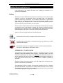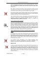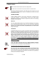
1
NXtension Expander Board NXtension-ES ES Monitor Software User Manual IMPORTANT SAFETY INSTRUCTIONS Declaration of conformity This equipment has been tested and found to comply with the safety objectives and essential requirements of European (73/23/EEC and 89/336/EEC directives) and international Standards, by fulfilling the requirements of the following harmonized standards: Electrical Safety (EU) : IEC 60065 (12/2001) Audio, video and similar electronic apparatus Electrical Safety (US) : UL60065 Seventh Edition, dated June 30, 2003 category AZSQ, E241312. Electrical Safety (CAN) : CSA-C22.2 N°60065:03 Edition, dated April 2003 category AZSQ7, E241312 Electrical Safety (Rest of the World) : CB test certificate DK-8371 based on IEC60065-2001 7nd ed. with all national deviations. Radiated Emission (EU) : EN55103-1 (1996) Electromagnetic compatibility - Product family standard for audio, video, audio-visual and entertainment lighting control apparatus for professional use. Audio Equipment 10CE Radiated Emission (US) : FFC part15 class B Radiated Emission (CAN) : This Class B digital apparatus complies with Canadian ICES-003. RF Immunity (EU) : EN55103-2 (1996) Electromagnetic compatibility - Product family standard for audio, video, audiovisual and entertainment lighting control apparatus for professional use. Note: EMC conformance testing is based on the use of recommended cable types. The use of other cable types may degrade EMC performances. Information about products that generate electrical noise : IMPORTANT SAFETY INSTRUCTIONS 1) Read these instructions. 2) Keep these instructions. 3) Heed all warnings. 4) Follow all instructions. 5) Do not use this apparatus near water. 6) Clean only with dry cloth. 7) Do not block any ventilation openings. Install in accordance with the manufacturer’s instructions. 8) Do not install near any heat sources such as radiators, heat registers, stoves, or other apparatus (including amplifiers) that produce heat. 9) Do not defeat the safety purpose of the polarized or groundingtype plug. A polarized plug has two blades with one wider than the other. A grounding type plug has two blades and a third grounding prong. The wide blade or the third prong are provided for your safety. If the provided plug does not fit into your outlet, consult an electrician for replacement of the obsolete outlet. (US market) 10) Protect the power cord from being walked on or pinched particularly at plugs, convenience receptacles, and the point where they exit from the apparatus. 11) Only use attachments/accessories specified by the manufacturer. 13) Unplug this apparatus during lightning storms or when unused for long periods of time. 14) Refer all servicing to qualified service personnel. Servicing is required when the apparatus has been damaged in any way, such as power-supply cord or plug is damaged, liquid has been spilled or objects have fallen into the apparatus, the apparatus has been exposed to rain or moisture, does not operate normally, or has been dropped. NOTE: The United States Federal Communications Commission (in 47 CFR 15.105) has specified that the following notice be brought to the attention of users of this product: This equipment has been tested and found to comply with the limits for a Class B digital device, pursuant to Part 15 of the FCC Rules. These limits are designed to provide reasonable protection against harmful interference in a residential installation. This equipment generates, uses and can radiate radio frequency energy and, if not installed and used in accordance with the instructions, may cause harmful interference to radio communications. However, there is no guarantee that interference will not occur in a particular installation. If this equipment does cause harmful interference to radio or television reception, which can be determined by turning the equipment off and on, the user is encouraged to try to correct the interference by one or more of the following measures: - Reorient or relocate the receiving antenna. - Increase the separation between the equipment and receiver. - Connect the equipment into an outlet on a circuit different from that to which the receiver is connected. - Consult the dealer or an experienced radio/TV technician for help. The user may find the following booklet, prepared by the Federal Communications Commission, helpful: How to identify and Resolve Radio/TV Interference Problems. This booklet is available from the U.S. Government Printing Office, Washington, D.C. 20402, Stock No. 004-000-00345-4. Use of a shielded cable is required to comply within Class B limits of Part 15 of FCC Rules. Pursuant to Part 15.21 of the FCC Rules, any changes or modifications to this equipment not expressly approved by NEXO S.A. may cause, harmful interference and void the FCC authorization to operate this equipment. CAUTION RISK OF ELECTRIC SHOCK DO NOT OPEN The lightning flash with arrowhead symbol, within an equilateral triangle is intended to alert the user to the presence of uninsulated “dangerous voltage” within the product's enclosure that may be of sufficient magnitude to constitute a risk of electric shock to persons. WARNING: To reduce the risk of fire or electric shock, do not expose this apparatus to rain or moisture. To avoid electrical shock, do not remove covers. Dangerous voltages exist inside. Refer all servicing to qualified personnel only. NXTENSION USER MANUAL DOCUMENT REVISION 150305 PAGE 2 The exclamation point within an equilateral triangle is intended to alert the user to the presence of important operating and maintenance (servicing) instructions in the literature accompanying the appliance. KNOWN BUGS & SOFTWARE ISSUES (15 MAR 05) Known bugs & software issues (15 mar 05) The software that you are going to install is the result of two months of field optimization. However it’s status is still a PRE-release status and it contains still some minor bugs & features that have not been fixed yet (and which may be described as working in the following pages). Please check our website www.nexo-sa.com periodically for updates. Please report bugs and feature requests to [email protected] ESmonitor Software The Input VU meters don’t indicate red when clipping. The orange zone of the vu-meter is not at -12dB. but earlier. Amplifier clipping is not represented on output VU meter. Changing setup: C&F key combination for accessing different cabinet families is not yet implemented. The software will issue a warning that you are changing family instead. Protection monitoring is not implemented. Firmware update via the network is not implemented. Global MUTE does not un-mute! Restore default button does not work Hard lock button does not work. SAVE/RECALL function is not implemented. We are sorry for any inconvenient the above list may cause. We are expecting to solve those points in the very near future. Note : THE ETHERSOUND DIGITAL OUTPUTS OF THE NX242 ARE CURRENTLY DISABLED, AS PROPERLY CONFIGURED ETHERSOUND AMPLIFIERS DO NOT YET EXIST. NXTENSION USER MANUAL DOCUMENT REVISION 150305 PAGE 3 KNOWN BUGS & SOFTWARE ISSUES (15 MAR 05) TABLE OF CONTENT IMPORTANT SAFETY INSTRUCTIONS ......................................................................................... 2 KNOWN BUGS & SOFTWARE ISSUES (15 MAR 05) .................................................................... 3 ESMONITOR SOFTWARE .......................................................................................................................... 3 FOREWORD .......................................................................................................................................... 5 NXTENSION-ES4 EXPANDER BOARD AT A GLANCE: .............................................................................. 5 UNPACKING .............................................................................................................................................. 5 HARDWARE INSTALLATION .......................................................................................................... 6 ESMONITOR SOFTAWRE ................................................................................................................. 9 NX242 REMOTE CONTROL PAGE .................................................................................................. 9 VIRTUAL NX242 TDCONTROLLER DIRECT ACCESS ............................................................................. 10 INPUT BOX ............................................................................................................................................ 10 INFO BOX .............................................................................................................................................. 11 OUTPUT BOX ........................................................................................................................................ 12 MASTER BOX ....................................................................................................................................... 13 SECURITY BOX ....................................................................................................................................... 13 SAVE/RECALL BOX ................................................................................................................................. 14 GROUP .................................................................................................................................................... 14 BUILDING ETHERSOUND NETWORKS ...................................................................................... 16 PREFACE ................................................................................................................................................ 16 ETHERSOUND NETWORK TOPOLOGIES ................................................................................................. 17 ETHERNET ADDITIONNAL HARDWARE ................................................................................................. 18 ETHERNET CABLES ......................................................................................................................... 20 ETHERNET CONNECTORS............................................................................................................. 22 NXTENSION USER MANUAL DOCUMENT REVISION 150305 PAGE 4 FOREWORD Foreword This manual is intended to help you to install and operate the NXtension-ES4 Expander Board. Please have a look the page devoted to NXtension-ES4 on NEXO website http://www.nexosa.com/asp/catalogue/products.asp?linkid=284&prodcode=NXtension-ES4 before installing your product to check if the release enclosed in the enclosed CDROM is the latest. This product is intended for use with the NX242 digital TDcontroller. Do not try to install it in an NX241 as damage could result. NXtension-ES4 Expander Board at a glance: o Double DSP resources & Setup memory of the NX242 TDcontrollers. o Remote Control potentials via WLAN and Internet, 100% Ethernet and TCP/IP compatible. o NX242 TDcontroller full remote control including Input/Output meters & protection monitoring o 4x Digital audio inputs from 64 uncompressed channels of 24bit/48kHz of audio transmission over Ethernet. (EtherSound protocol) o 4x NX242's processed digital audio outputs to 64x uncompressed 24bit/48kHz channels of audio transmission over Ethernet. Unpacking The NXtension Expander Board package should contain: - the NXtension-ES4 Expander Board - 2x M3x4 screws for replacing blank panel (rear of the NX242) - 3x M3x5 screws for fastening the NXtension Expander Board in the NX242 - 1x CD ROM containing this manual, the LOAD needed for updating the firmware of the NX242 and the ESmonitor software to control the NX242 - this manual NXTENSION USER MANUAL DOCUMENT REVISION 150305 PAGE 5 HARDWARE INSTALLATION Hardware Installation The card contains sensitive electric components, which can be easily damaged by static electricity, so the card should be left in its original packing until it is installed. Before touching the card make sure that you discharge yourself of static electricity. Ideally, you should wear a grounded anti-static wrist strap when servicing electronic units. As a minimum, make sure your body is touching the metal frame of the NX242 before removing the NXtension-ES4 from its anti static package. NOTE: the NXtension Expander Board with the EtherSound extension MUST only be installed in a NX242 Digital TDcontroller. 1. Remove the top panel of the NX242 (11 screws) 2. Remove the blank panel located on the back panel (2 screws). DO NOT USE THESE SCREWS WITH THE NXtension card, AS THEY ARE TOO LONG AND WILL DAMAGE THE PCB. 3. Remove the 7 jumpers located on the header CN5001. The positions of the jumpers are illustrated below, in case you need to remove the board and run the NX242 without the expander board fitted. NXTENSION USER MANUAL DOCUMENT REVISION 150305 PAGE 6 HARDWARE INSTALLATION 4. Insert the NXtension Expander Board in the NX242 by sliding the upper left corner of the NXtension Expander Board under the corner of the rear panel of the NX242 back panel until there is enough room to place the upper right corner inside the NX242. (Supposing that you are facing the front panel of the NX242) NXTENSION USER MANUAL DOCUMENT REVISION 150305 PAGE 7 HARDWARE INSTALLATION 5. Align the NXtension Expander Board on the axis of the spacer ME0004, ME0006 and ME0008, push gently to insert the board. 6. Screw the NXtension Expander Board into the spacers (3 screws M3x5). Use the screws provided with the NXtension package. 7. Screw the rear panel of the NXtension Expander Board to the rear panel of the NX242 (2 self taping screws M3x4). Use the screws provided with the NXtension package. 8. Replace the top panel. Pay special attention to the screws above the aluminum heat sink. Only apply a light torque to avoid damaging the thread in the aluminum. 9. Update the NX242 firmware to allow the NXtension Expander Board to be activated. Follow the standard updating instructions given in the NX242 user manual (or documentation provided with the LOAD). NXTENSION USER MANUAL DOCUMENT REVISION 150305 PAGE 8 ESMONITOR SOFTAWRE ESmonitor Softawre Please refer to AUVITRAN “AVS-ESMonitor USER MANUAL” that can be downloaded on AUVITRAN website http://www.auvitran.com . This contains any information about software installation and use. Specific information about the NX242 control page is given below. NX242 remote Control Page The Graphical User Interface (GUI) is divided in to several boxes, containing commands that are related together (INPUT, OUTPUT, INFO…). NXTENSION USER MANUAL DOCUMENT REVISION 150305 PAGE 9 NX242 REMOTE CONTROL PAGE Virtual NX242 TDcontroller direct access At the top of the GUI, a virtual NX242 front panel allows real-time control of all NX242 function(s). The screen (identically) emulates a real NX242 screen – every buttons is functional and the jog wheel can be controlled by clicking on the left/right arrows. INPUT box A radio button selects between 4 digital inputs and 2 digital inputs plus 2x analogue inputs. Dependent on this choice the Input box will differ slightly. In both cases an “array EQ gain” is present. The value of the gain can be typed directly into the text box. Digital IN The four input bar graphs display on a logarithmic scale the input signal. 0dB is the digital full-scale value, where the AD converter clips. When clipping occurs the whole bar graph becomes red. –12dB zone is orange. The dynamic of the bar graph is 96dB. Above the bar graph, the EtherSound channel is displayed (also visible in the routing tab of the ESmonitor). Headroom settings have no meaning in digital IN and are not present. (The goal of the headroom is to adjust the Analogue Gain in drive the AD converter full scale) NXTENSION USER MANUAL DOCUMENT REVISION 150305 PAGE 10 NX242 REMOTE CONTROL PAGE Analogue IN Two analogue input channels (A&B) and two digital inputs channel (corresponding to the ES routing) are visible. The headroom setting allows the scaling of the analogue signals before the AD converter. In an analogueanalogue mode this setting does not affect the overall gain (the inverse gain is performed after the DA conversion). The scale to the right of the slider shows the maximum level that the analogue input can take before clipping. These Analogue In bar graphs behave, as above, in the Digital In function. INFO box This box displays useful information for the user NX242 Name: By default the MAC address. It can be selected and changed in the text edit box to have a more user friendly name. The change is updated in the EtherSound network column (left). Reciprocally double clicking in the left column will open a dialogue box in which the name can be changed. Current Setup: Displays the cabinet family setup name as it is written in the NX242 (2x16 letters). Change setup (SET): This button changes the setup within the same family. Changing cabinet family (from a PS10 to a GEOT) implies physical changes and can be dangerous if not done intentionally. To avoid any mistake the keys “C” & “F” must be held on the keyboard while clicking on the Set button to be able to access setups from a different cabinet family. Version: Displays the different version of the LOAD (concatenation of DSP software and cabinet parameter setup), DSP software. If the DSP software version is different within the NX242 connected to the network a small warning sign appears near older revision numbers. If the DSP software needs a newer control software (second digit of the revision) the EScontrol software sends a warning prompt, in red, in the Version box: Please update the control software. Serial number: Kept in non-volatile memory, this allows a simpler identification than the MAC address and may be useful to physically identify the NX242 location within the racks. NXTENSION USER MANUAL DOCUMENT REVISION 150305 PAGE 11 NX242 REMOTE CONTROL PAGE OUTPUT box From top to bottom Channel label: This duplicate the channel name displayed in the NX242 Interchannel Gain: range from –6 to +6dB in step of 0.5dB. The value of the gain can be entered directly in the text box. Bargraph: Represents the output level in dBu (absolute). The red zone corresponds to amplifier clipping. –6dB zone is orange. Mute/Solo button: Mute or solo the channel according to the setting in the master box (so the label is changing with that option). These buttons change from grey to red when muted. In solo mode, all other buttons become red when the solo is pressed. Interchannel Delay: The delay can be set either by typing it in the edit box, or by pressing the + or – button. In any case, the value is rounded according to the NX step. A clear unit label (m, ms, ft) is shown near the edit box, according to the unit option selected in the master box. Patch: The patch allows change the outputs/input matrix. According to the “’analogue/digital” choice, in the input box, an unused channel is faded. Pressing a button changes its color. Several buttons can be pressed, to sum the inputs. Number shown on the digital buttons are relative to EtherSound routing. Protection monitoring: Two bar graphs are displayed by channel, Temperature and displacement. The top of the scale is +3dB. 0dB is the place where protection takes place. Bottom is –20dB. Log scale. Red zone from 0 to +3dB, orange zone from –6 to 0. Peaks are hold according to the master box option. In case of a passive cabinet (so two driver are using the same channel) a max of both temperature or displacement is taken. Physio-control is not taken into account. Amplifier gain and power: Four text boxes display the user gain and the read gain, plus the user gain and power. These last values are used in the formula that determines the red zone of the output VU meter. The “read” values are seen only in the text box, and user-editable by typing a desired value. NXTENSION USER MANUAL DOCUMENT REVISION 150305 PAGE 12 NX242 REMOTE CONTROL PAGE MASTER box This part of the GUI provides information and global control settings. Global Gain(Master): From –6 to 6dB in 0.5dB step. Gain can be typed into text box, or the slider can be moved with the mouse. Global Mute: Mutes all channels. This button stays Mute, regardless of the Mute/Solo option. Global Delay: same as interchannel delay but affect all channels. Delay Units: Allows choice between meters, feet or milliseconds. Changes the label near the Delay textboxes. Mute/Solo option : Toggles the channel Mute buttons into Solo buttons. Changes the label on those buttons, and the way they change color. Does not affect global mute button Sense alarm: Enables or disables the Sense alarm (when user gains are different than read gains) Reset Measurement: Double click on the Meas box to reset the reading Security box Restore default values: NX242 user-adjusted values will all return to default state (gain and delay to zero…) Freeze and Unfreeze local NX controls: Enable or disable the command on the NX242 itself (read only). Freeze Unfreeze ALL(Hard Lock): Prevent any changes to be made locally on the NX242 and on the PC. A password is asked (and sent) to the NX242. NXTENSION USER MANUAL DOCUMENT REVISION 150305 PAGE 13 NX242 REMOTE CONTROL PAGE Save/recall box The Save and recall buttons store NX242 memory parameters. (This allows them to be recalled without PC control.) Group Creating, removing groups Group management is achieved by right clicking in the Group view window (in the left frame) and selecting the desired menu function. Each time a new group is created, a corresponding button is inserted in the group box of each NX242 control page, and in the group box (properties tab) of each EtherSound device. Affecting NX242 to groups Once a button corresponding to the group has been created, push this button to link the corresponding NX242 to the Group. The button will change color, and the selected NX242 will appear in the left group frame. However the following restrictions prevent change of an NX grouping. - Another EtherSound element belongs already to the group (as a patch panel or YGDAI card). - NX242s with different setups can’t be put into the same group. Group buttons, that can’t be accessed, are grayed. Group mode When the group is selected in the Group view frame, group mode is enabled. The Control window displayed is then a global view of each NX242s under control. In this mode, each command is duplicated on every NX242 belonging to the group. You can command the NX242 individually by click-choosing the particular unit. In that situation, the settings will no longer remain locked to the rest of the group. This is shown by turning the setting color to orange, or displaying a small orange spot near NXTENSION USER MANUAL DOCUMENT REVISION 150305 PAGE 14 NX242 REMOTE CONTROL PAGE the command (in both the group view and individual view). Remember that changing this command again, in Group view, will reset according to the group value. The universal group mode view shows always the maximum value within all NX242 grouped (i : maximum bar graph, max delay, etc.…). When the notion of maximum is irrelevant, an orange X is displayed (for the patch number for instance). Any NX242 can belong to several groups. NXTENSION USER MANUAL DOCUMENT REVISION 150305 PAGE 15 BUILDING ETHERSOUND NETWORKS Building EtherSound Networks Large segments of this chapter are taken from “building ES Networks V1.0”. (Courtesy of DIGIGRAM) Preface EtherSound uses standardized and well-proven technology from the world of digital networks, in order to cost-effectively convey high-quality audio. The EtherSound protocol provides fully deterministic, very low-latency transmission of synchronized audio channels over standard Ethernet. Up to 64 bi-directional channels of 24-bit digital audio may be transported at 44.1 or 48kHz among a virtually infinite number of connected devices, along with status and control data. This document is a short introduction to the characteristics of Ethernet, the conception of EtherSound, and to EtherSound’s interplay with Ethernet components and the Ethernet protocol. It also gives some recommendations for equipment that has been tested at Digigram and found to comply with the EtherSound requirements. Watch out for these symbols beside the corresponding text: indicates that this technology is suitable for EtherSound networks. designates that the technology or material described is to be avoided in the context of EtherSound networks. indicates that the chapter or paragraph in question contains important additional information or differentiations, READ WITH CARE ! ETHERSOUND – TO KEEP IN MIND The EtherSound protocol by Digigram is based on true Ethernet frames. It is fully compliant to Ethernet IEEE 802.3 frame format. It is full-duplex (data is sent and received simultaneously) and requires a dedicated Fast Ethernet network, as it cannot share data with other elements on a network. Data is typically transported via Local Area Networks (LANs) with a minimum bandwidth of 100Mbps (100BaseTX) full-duplex. EtherSound allows real-time transmission of 64 high-quality audio channels (24 bits, 48 or 44.1 KHz) with a very low latency. The EtherSound protocol provides communication between devices by inserting formatted EtherSound sub-packets into standard Ethernet frames. Audio channel synchronization is based on valid EtherSound frame arrival. Each frame is transmitted at a defined sampling frequency (44.1 or 48kHz). NXTENSION USER MANUAL DOCUMENT REVISION 150305 PAGE 16 BUILDING ETHERSOUND NETWORKS Analog and digital filters ensure clock recovery and a minimum of jitter. Nevertheless, network equipment can introduce jitter that inhibits filter operation and sample extraction from the EtherSound frame, causes sample loss and degrades audio performance. EtherSound network topologies EtherSound devices may be daisy chained or use a Star architecture (in this case switches must be used), or a combination of both. Daisy Chain Star Configuration NXTENSION USER MANUAL DOCUMENT REVISION 150305 PAGE 17 BUILDING ETHERSOUND NETWORKS Mixed Daisy Chain & Star Configuration Ethernet Additionnal hardware Hubs A hub (also known as repeater) is a central connection point for computers on a startopology-based network. Any data it receives is broadcasted to all ports, and then only the computer that is ‘listening’ for the data actually receives and processes the transmission. Hubs are the ‘unintelligent’ relatives of switches. Due to their internal architecture, repeater hubs MUST NOT be used in EtherSound networks. Switches The term “Ethernet Switch” is now used for multiple-port-devices that are able to filter and forward frames at nearly the speed of Ethernet (‘wire speed’). The two most common methods used for routing the traffic are: • Cut-through: These switches read the MAC (Media Access Control) address as soon as a frame is detected by the switch and immediately begin sending the frame to the destination node, even as the rest of the frame is coming into the switch. • Store-and-forward: a switch using store-and-forward saves the entire frame to the buffer and checks it for CRC errors or other problems before sending. If the frame has an error, it is discarded. Otherwise, the switch looks up the MAC address and sends the frame on to the destination node. A switch is a multi-port device that filters and NXTENSION USER MANUAL DOCUMENT REVISION 150305 PAGE 18 BUILDING ETHERSOUND NETWORKS forwards data between network devices. Unlike a standard repeater hub, a switch is able to read the destination address of each frame and then forward it to the correct port. This ‘intelligence’ in the switch means that a device receives only those frames addressed to it. Many switches combine the two methods, using cut-through until a certain error level is reached and then changing over to store-and-forward (Error free Cut-through). Very few switches are strictly cut-through, since this provides no error correction. Some switches provide a function called broadcast storm in order to guarantee the maximum bandwidth available and prevent network overload by limiting broadcast messages; this function can not be used with EtherSound. There are different types of switches, using different protocols that interact with other protocols to provide all the necessary transmission services. The outline for implementing protocols in altogether seven layers is defined in a worldwide ISO standard called OSI (Open System Interconnection) Layer 2 (Data Link Layer) switches Layer 2 is the communication protocol that contains the physical address of a network device. It is called the “data link layer” or “MAC (=Media Access Control) layer” and contains the address inspected by a bridge or switch. Layer 2 processing is faster than layer 3 processing, because less analysis of the frame is required. As the EtherSound protocol contains exclusively layer 2 information, switches other than layer two must not be used. These layer 2 switches can be either managed or unmanaged. Managed switches are necessary to set up VLAN networks so that EtherSound can co-exist on a larger network with other applications. Layer 3 (Network Layer) and Layer 4 (Transport Layer) switches, Routers As opposed to Layer 2 switches, the switching decision of these devices is based on the IP header of each frame. The more intensely a frame is examined, the more forwarding decisions can be made based upon type of traffic, quality of service, .etc. In order to get to this information though, the frames’ headers have to be investigated in detail, and need an IP header, which is not the case when EtherSound is based on the Ethernet (Layer 2) protocol. Some switches provide functionalities of the so-called SPANNING TREE PROTOCOL for inter-switch communication and network management. The EtherSound protocol is NOT COMPATIBLE with the Spanning Tree Protocol. Wireless LAN A local area network that transmits over the air typically (but not exclusively) in an unlicensed frequency or, among others, infrared line of sight. Wireless access points (base stations) are connected to an Ethernet hub or server and transmit a radio frequency that can penetrate walls and other non-metal barriers. Roaming users can be handed off from one access point to another like, for example, in a cellular phone system. Wireless LANs are not suitable for EtherSound networks due to significant bandwidth limitations. NXTENSION USER MANUAL DOCUMENT REVISION 150305 PAGE 19 BUILDING ETHERSOUND NETWORKS ETHERNET CABLES Cables used within the EtherSound network are straight cables. The cable used to connect the PC to the primary master is a crossover cable The following paragraphs describe the main cable types used. Among them, you will find descriptions of cables listed for reasons of completeness, but that are not suited for EtherSound networks. ThickNet (ThickWire) ThickNet (10Base5 Ethernet) is a thick, bulky, coaxial cable. It is generally used to create large “backbones”. A network backbone connects many smaller network segments into one large LAN. ThickNet can support many nodes in a bus topology, the segment can be quite long. Thin Coax Thin coax (10Base2 Ethernet) offers many of ThickNet’s advantages for bus topology, but it is less expensive and easier to install. Thin coax coaxial cable is significantly thinner and more flexible than ThickWire, but it supports only 30 nodes. With these restrictions, thin coax can still be used to create backbones, but is rather used to design small networks. Twisted Pair Unshielded twisted pair (UTP) is similar to the telephone cable that may already be installed in your building and available for network use. There are several grades of UTP cables, each higher grade offering better performance. Level 1 and Level 2 cables are the lowest grades and least expensive ones, designed primarily for lowspeed and voice transmissions (less than 5Mbps). They should not be used in the design of 10BaseT networks. Level 3 and Level 4 cables are very common for current 10BaseT configurations; Level 3 cable can support speeds of up to 16Mbps (32Mbps in full-duplex), Level 4 up to 20Mbps (40Mbps in full-duplex). All these cables use RJ45 connectors. In order to maintain the electromagnetic performance and diminish the number of possible errors DO NOT USE unshielded twisted paris. CAT5, 5e, 6, 7 cables Level 5 cable supports transmission rates of up to 100Mbps (200Mbps in full-duplex), CAT5e, even 1Gbps - is the most common today. Category 6 supports up to 10Gbps, for CAT6 and CAT7 new standards are under development. Horizontal (solid) cable and patch (stranded) cable Both UTP and STP come in stranded and solid wire varieties. The stranded wire is the most common and is also very flexible for bending around corners. Solid wire cable has less attenuation and can span longer distances, but is less flexible than stranded wire and cannot be repeatedly bent (and therefore not suitable for live applications). Following are the twisted pair categories. NXTENSION USER MANUAL DOCUMENT REVISION 150305 PAGE 20 BUILDING ETHERSOUND NETWORKS Horizontal cable (also called solid cable) is made of plain copper conductors and has a low characteristics shift with aging. It must be used for long runs of steady cabling (typically the cables inside walls and ceiling). Patch cable (also called stranded cable), more flexible, is made of stranded copper conductors and has larger losses and characteristics shifts than horizontal cable. It can be used for versatile termination between wall outlet and device, or between devices. These cables are explicitly labeled “PATCH”. The TIA/EIA 568A wiring standard allows the use of horizontal cable up to 90m(295ft) lengths with a maximum amount of 10m of patch cable for both ends added together. UTP, FTP (ScTP), STP, SFTP cables o UTP stands for Unshielded Twisted Pair. It is a cable type with one or more pairs of twisted insulated copper conductors contained in a single sheath. It is the most common type of cabling used in desktop communications applications. For performance sake and electromagnetism behavior, the UTP cables shall NOT be used. o FTP stands for Overall Foil Shielded Twisted Pair (ScTP for Screened Twisted Pair): Cable is wrapped with an aluminized plastic foil). That kind of cabling is not recommended for applications where the cable is repeatedly bent. The foil tends to break leading to severe loss of performance over the distance. Do not use FTP cabling for live application. o STP stands for Shielded Twisted Pair: Screen is made of copper braid. o SFTP stands for Overall Braid + Foil Shielded Twisted Pair: Foil screen and braid shield. For all these cables, transmission characteristics are the same. The difference is the behavior with respect to electromagnetic interference. We recommend cabling that has a superior quality sleeve in order to protect the cable. Ideally this sleeve should halogen free in order to comply for the installation standards. Typical cable characteristics (approximate values, for your information): Characteristics @ 100 MHz Attenuation (dB/100 m) Near-end cross talk (N.E.X.T., dB) Horizontal cable CAT5e 22 35 Patch cable CAT5e 32 35 Horizontal cable CAT6 20 45 Patch cable CAT6 n.a. n.a. Horizontal cable CAT7 19 72 Patch cable CAT7 28 72 NXTENSION USER MANUAL DOCUMENT REVISION 150305 PAGE 21 BUILDING ETHERSOUND NETWORKS Fiber Optic Fiber Optic is similar to twisted pair but does not conduct electricity. It is used in situations where a network may suffer from environmental conditions (e.g. lightning), such as in LAN connections between buildings. Fiber optic is also very valuable where electronic emissions or electro-magnetic interferences may have an impact on the network, e.g. on particular factory floors. Furthermore, fiber optic cables and Ethernet standard allow for segments up to two km(1.24mi) long (cf. thin coaxial • 185m(607ft), UTP • 100m(328ft)) and thus permit to connect remote nodes and buildings that otherwise would not be accessible. To use Fiber Optic cable in EtherSound networks, Media Converters must be used. ETHERNET CONNECTORS The Ethernet connector equipping your cable shall ensure a good metallic coupling with the metal box of the NX242 digital TDcontroller. NEXO recommends NEUTRIK ETHERCON connectors. NXTENSION USER MANUAL DOCUMENT REVISION 150305 PAGE 22 USER NOTES User notes NXTENSION USER MANUAL DOCUMENT REVISION 150305 PAGE 23 France Nexo S.A. 154 allée des Erables ZAC des PARIS NORD II B.P. 50107 F-95950 Roissy CDG Cedex Tel: +33 1 48 63 19 14 Fax: +33 1 48 63 24 61 e-mail: [email protected] USA Nexo USA Inc. 2165 Francisco Boulevard Suite E2 San Rafael CA 94901 Tel: +1 415 482 6600 Fax: +1 415 482 6110 e-mail: [email protected] LatAM Nexo Latin America Hualfin 1054 1424 Capital Federal Argentina Tel +54 114 432 1911 Fax +54 114 431 1007 e-mail: [email protected] Far East Nexo Far East Pte. Ltd. No. 10 Ubi Crescent #02-35/36 Ubi Techpark (Lobby C) SINGAPORE 408564 Tel: +65 742 5660 Fax: +65 742 8050 e-mail: [email protected] www.nexo-sa.com