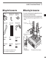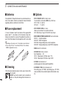
1
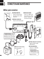
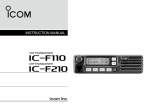
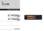
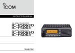
Limited functions only INSTRUCTION MANUAL VHF MOBILE TRANSCEIVERS iF5010 Series UHF MOBILE TRANSCEIVERS iF6010 Series IMPORTANT FCC INFORMATION READ ALL INSTRUCTIONS carefully and com- pletely before using the transceiver. SAVE THIS INSTRUCTION MANUAL — This instruction manual contains important operating instructions for the IC-F5011, IC-F5013, IC-F5013H VHF MOBILE TRANSCEIVERS and the IC-F6011, IC-F6013, IC-F6013H UHF MOBILE TRANSCEIVERS. EXPLICIT DEFINITIONS WORD DEFINITION R WARNING! Personal injury, fire hazard or electric shock may occur. CAUTION NOTE Equipment damage may occur. If disregarded, inconvenience only. No risk of personal injury, fire or electric shock. Icom, Icom Inc. and the Icom logo are registered trademarks of Icom Incorporated (Japan) in Japan, the United States, the United Kingdom, Germany, France, Spain, Russia and/or other countries. All other products or brands are registered trademarks or trademarks of their respective holders. i • FOR CLASS B UNINTENTIONAL RADIATORS: This equipment has been tested and found to comply with the limits for a Class B digital device, pursuant to part 15 of the FCC Rules. These limits are designed to provide reasonable protection against harmful interference in a residential installation. This equipment generates, uses and can radiate radio frequency energy and, if not installed and used in accordance with the instructions, may cause harmful interference to radio communications. However, there is no guarantee that interference will not occur in a particular installation. If this equipment does cause harmful interference to radio or television reception, which can be determined by turning the equipment off and on, the user is encouraged to try to correct the interference by one or more of the following measures: • Reorient or relocate the receiving antenna. • Increase the separation between the equipment and receiver. • Connect the equipment into an outlet on a circuit different from that to which the receiver is connected. • Consult the dealer or an experienced radio/TV technician for help. CAUTION: Changes or modifications to this transceiver, not expressly approved by Icom Inc., could void your authority to operate this transceiver under FCC regulations. PRECAUTIONS R WARNING! NEVER connect the transceiver to an AC outlet. This may pose a fire hazard or result in an electric shock. DO NOT use or place the transceiver in areas with tem- R WARNING! NEVER connect the transceiver to a power source of more than 16 V DC or use reverse polarity. This could cause a fire or damage the transceiver. DO NOT operate the transceiver without running the vehicle’s engine. The vehicle’s battery will quickly run out when the transceiver transmits while the vehicle’s engine is OFF. R WARNING! NEVER cut the DC power cable between the DC plug and fuse holder. If an incorrect connection is made after cutting, the transceiver might be damaged. ronments. R WARNING! NEVER place the transceiver where normal operation of the vehicle may be hindered or where it could cause bodily injury. CAUTION: NEVER allow children to touch the trans- ceiver. CAUTION: NEVER expose the transceiver to rain, peratures below –30°C (–22°F) or above +60°C (+140°F), or in areas subject to direct sunlight, such as the dashboard. DO NOT place the transceiver in excessively dusty envi- DO NOT place the transceiver against walls. This will obstruct heat dissipation. DO NOT use harsh solvents such as benzine or alcohol when cleaning, as they will damage the transceiver surfaces. BE CAREFUL! The transceiver will become hot when operating continuously for long periods of time. snow or any liquids. USE the specified microphone only. Other microphones have different pin assignments and may damage the transceiver. Approved Icom optional equipment is designed for optimal performance when used with an Icom transceiver. Icom is not responsible for the destruction or damage to an Icom transceiver in the event the Icom transceiver is used with equipment that is not manufactured or approved by Icom. ii TABLE OF CONTENTS IMPORTANT........................................................................... i EXPLICIT DEFINITIONS........................................................ i FCC INFORMATION.............................................................. i PRECAUTIONS..................................................................... ii TABLE OF CONTENTS........................................................ iii iii 1 PANEL DESCRIPTION.................................................1–6 ■ Front panel....................................................................1 ■ Function LED................................................................2 ■ Programmable function keys.........................................3 2 BASIC OPERATION...................................................7–13 ■ Turning ON the power...................................................7 ■ Channel selection..........................................................7 ■ Call procedure...............................................................8 ■ Receiving and transmitting............................................8 ■ User Set mode............................................................10 ■ Scrambler function......................................................11 ■ Stun function...............................................................11 ■ Priority A channel selection.........................................11 ■ Emergency transmission.............................................12 ■ MDC 1200 system operation.......................................13 3 CONNECTION AND MAINTENANCE.....................14–16 ■ Rear panel connection................................................14 ■ Supplied Accessories..................................................15 ■ Mounting the transceiver.............................................15 ■ Antenna.......................................................................16 ■ Fuse replacement.......................................................16 ■ Cleaning......................................................................16 ■ Options........................................................................16 4 SAFETY TRAINING INFORMATION..............................17 PANEL DESCRIPTION 1 ■ Front panel Function LED (p. 2) q 1 2 3 Speaker 4 TX/RX P0 P1 w P2 e P3 r qAF VOLUME CONTROL KNOB [VOL] Rotate the knob to adjust the audio output level. rPOWER KEY [ ] Push to turn the power ON or OFF. • The following optional functions are available at power ON: - Automatic scan start - Password prompt - User Set mode • Minimum audio level is pre-set. (p. 10) wMICROPHONE CONNECTOR Connect the supplied or optional microphone. NEVER connect non-specified microphones. The pin assignments may be different and the transceiver may be damaged. 1 2 3 4 5 6 7 8 9 10 11 12 13 14 15 16 eDEALER-PROGRAMMABLE KEYS Desired functions can be independently programmed by your dealer. (p. 3) 1 1 PANEL DESCRIPTION ■ Function LED D MICROPHONE q 1 2 3 The supplied or optional microphone has a PTT switch and a hanger hook. 4 TX/RX e w qCHANNEL INDICATORS ➥ Indicates the operating channel. ➥ Blinks when receiving a signal during a scan. ➥ All LEDs blink while entering the power ON password. wTX/RX INDICATOR ➥ Lights red while transmitting. ➥ Lights green while the channel is busy (receiving). ➥ Blinks orange when the specified 2-tone, 5-tone call is received. ➥ Alternately blinks green and red when a cloning error has occurred. eACTIVATED KEY INDICATORS (P0/P1/P2) L ights when a pre-programmed key function is activated. 2 OTE: When the supplied DC voltage is low, all LEDs N blink. Check the DC voltage. • The following functions are available when the microphone is ON or OFF hook (depending on the preprogramming): - Automatic scan start when you put it ON hook. - Scan is cancelled when you take it OFF hook - Scan is paused when you take it OFF hook - Automatically selects the Priority A channel when you take it OFF hook. - Sets to ‘Inaudible’ mode (muted state) when you put it ON hook. - Sets to ‘Audible’ mode (unmuted state) when you take it OFF hook. PANEL DESCRIPTION ■ Programmable function keys The following functions can be assigned to [P0], [P1], [P2] and [P3] programmable function keys. Consult your Icom dealer or system operator for details concerning your transceivers programming. CH UP AND DOWN KEYS Push to select an operating channel. SCAN A START/STOP KEY Push to start or cancel a scan. SCAN B START/STOP KEY Push to start or cancel a scan. When a scan started with the Power ON Scan or by pushing this key, push to cancel it. If the scan is cancelled except by pushing this key, the cancelled scan resumes after the specified time period. SCAN ADD/DEL (TAG) KEY While scan is paused by a detected signal, on a channel other than a priority channel, push this key to clear the channel from the scan list. epending on the preprogramming, the cleared channel is D added to the scan list again after the scan is cancelled. 1 PRIO A/B KEYS ➥Push to select Priority Channel A or B. ➥To rewrite the operating channel as Priority A or Priority B, hold down [Prio A (Rewrite)] or [Prio B (Rewrite)] for 1second. MR-CH 1/2/3/4 KEYS Push to directly select memory channels 1 to 4. MONI (AUDI) KEY ➥ Push to turn the CTCSS (DTCS) or 2/5-tone squelch Mute ON or OFF. • Only during LMR operation, hold down to open any squelch functions, or deactivate any mute functions. • Only during PMR operation, push to activate one or two of the following functions* on each channel. - Hold down to unmute the channel (Audible mode). - Push to mute the channel (Inaudible mode). - Push to send a ‘reset code’ after the communication is finished. *Ask your dealer for details. OTE: After a specified period, the un-muted state (‘AuN dible’ mode) may automatically return to the muted state (‘Inaudible’ mode), depending on the preprogramming. 1 2 3 4 5 6 7 8 9 10 11 12 13 14 15 16 ➥ Hold down this key for 1 second to cancel a scan, depending on the preprogramming. 3 1 PANEL DESCRIPTION ■ Programmable function keys (continued) LOCK KEY Hold down to electronically lock all programmable keys except the following: [Moni(Audi)], [Lock], [Call] (incl. Call A and Call B), [Emergency], [Surveillance], [Siren] and [Lone Worker]. DTMF AUTODIAL KEY Push to transmit a DTMF code. RE-DIAL KEY Push to transmit the last-transmitted DTMF code. • TX memories are cleared after turning OFF the transceiver. LONE WORKER KEY Push to turn the Lone Worker function ON or OFF. • If the Lone Worker function is activated, the Emergency function is automatically turned ON after the specified time period has passed with no operation performed. HIGH/LOW KEY Push to select the transmit output power level temporarily or permanently, depending on the preprogramming. • Ask your dealer for the output power level for each selection. TALK AROUND KEY Push to turn the talk around function ON or OFF. • The talk around function equalizes the transmit frequency to the receive frequency for transceiver-to-transceiver communication. WIDE/NARROW KEY Push to toggle the IF bandwidth between wide and narrow. • The wide passband width can be selected from 25.0 or 20.0 kHz using the CS-F3020/F5010/F5020 cloning software. (PMR operation only) Ask your dealer for details. 4 CALL KEYS Push to transmit a 2/5-tone ID code. • Tone call transmission may be necessary before you call another station, depending on your signalling system. • [Call A] and/or [Call B] may be selectable when your system employs selective ‘Individual/Group’ calls. Ask your dealer which call is assigned to each key. EMERGENCY KEY Hold down for a specified period to transmit an emergency call. • Beeps sound when the emergency call is transmitted. • The transceiver can transmit an emergency call without the beep sounding and the LED indicator lighting. Ask your dealer for details. • If you want to cancel the emergency call, hold down the key again, before transmitting the call. • The emergency call is transmitted only one time, or repeatedly until receiving an acknowledgement signal, or until the power is turned OFF. When a matched 5-tone code signal is received, the emergency function can be cancelled depending on the presetting. (PMR operation only) PANEL DESCRIPTION SURVEILLANCE KEY Push to turn the surveillance function ON or OFF. When this function is turned ON, the beeps do not sound the LED does not light when a signal is received or a key is pushed. SIREN Hold down for 1 second to sound the siren. This function can be used for situations other than an emergency alert, such as a security alarm for example. • The siren can only be stopped by turning OFF the transceiver power. SCRAMBLER KEY Push to turn the voice scrambler function ON or OFF. HOOK SCAN When the Hook Scan function is pre-programmed, push this key to temporarily disable the function. Push this key again to enable the function. 1 USER SET MODE KEY ➥Hold down for 1 second to enter the User Set mode. 1 • During User Set mode, push this key to select an item*, and change the value or setting using [CH Up]/[CH Down]. *Selectable items may differ depending on the pre-setting. ➥Hold down this key for 1 second again to exit the User Set mode. The User Set mode is also available via the ‘Power ON’ function. In this case, all set mode items are available. Refer to page 10 also. OPT 1/2/3 OUT KEYS Push to output the control signal to option connector. Ask your dealer for details. OPT 1/2/3 MOMENTARY KEYS Outputs the control signal to the option connector while holding down this key. Ask your dealer for details. 5 1 PANEL DESCRIPTION ■ Programmable function keys (continued) Ext. CH Sel Mode KEY Push to turn the Ext. CH Select function ON or OFF. When the function is turned ON, memory channels can be selected with external input operation only. When the function is turned OFF, memory channels can be selected with [CH Up] or [CH Down] operation, or with external input operation. • This function is available when the external unit, such as a dimmer control is connected to the transceiver with the optional OPC-1939 or OPC-2078 cable (p. 16). • Ask your dealer for details of external input operation. 6 BASIC OPERATION 2 ■ Turning ON the power ■ Channel selection qPush [ ] to turn ON the power. wIf the transceiver is programmed for a start up password, input the digit codes as directed by your dealer. There are several methods to select channels, and they may differ, according to your system set up. • The keys shown below can be used for password input: The transceiver detects numbers in the same block as identical. Therefore “01234” and “56789” are the same. Push [CH Up] or [CH Down] to sequentially select the desired operating channel, or push one of the [MR-CH 1] to [MR-CH 4] keys to select a channel directly. KEY NUMBER P0 P1 P2 P3 0 1 2 3 4 5 6 7 8 9 eIf all channel indicator LEDs still blink after inputting 4 digits, the input code number may be incorrect. Turn OFF the power and re-enter your password. AUTOMATIC SCAN TYPE: Channel setting is not necessary for this type. When turning ON power, the transceiver automatically starts scanning. Scanning stops when a signal is detected. 1 2 3 4 5 6 7 8 9 10 11 12 13 14 15 16 7 2 BASIC OPERATION ■ Call procedure ■ Receiving and transmitting When your system employs tone signaling (excluding CTCSS and DTCS), a call procedure may be necessary prior to voice transmission. The tone signalling employed may be a selective calling system which allows you to call specific station(s) only and prevents unwanted stations from contacting you. Receiving: qHold down [ ] for 1 second to turn ON the power. wPush [CH Up] or [CH Down] to select a channel. eWhen receiving a call, rotate [VOL] to adjust the audio output level to a comfortable listening level. qSelect the desired TX code channel and a 2/5-tone code, according to your System Operator’s instructions. NOTE: Depending on the preprogramming, the transceiver automatically transmits the microphone audio for the specified time period* when a matched RX code signal is received. • This may not be necessary, depending on the preprogramming. • Refer to pages 9 and 10 for selection. wPush [Call] (assigned to one of the dealer programmable keys). eAfter transmitting, the remainder of your communication can be carried out in the normal fashion. Selective calling Non-selective calling • HM-148G or HM-152 hand microphone is required. * Depending on the preprogramming. Ask your dealer for details. Transmitting: Wait for the channel to become clear to avoid interference. qTake the microphone off hook. • The ‘audible’ condition is selected. • A priority channel may be automatically selected. wWait for the channel to become clear. • The channel is busy when the TX/RX indicator lights green. eWhile holding down [PTT], speak into the microphone at your normal voice level. rRelease [PTT] to return to receive. IMPORTANT: To maximize the readability of your signal; 1. Pause briefly after pushing [PTT]. 2. H old the microphone 5 to 10 cm (2 to 4 inches) from your mouth, then speak into the microphone at a normal voice level. 8 BASIC OPERATION D Transmitting notes •Transmit inhibit function The transceiver has several inhibit functions which restrict transmission under the following conditions: - The channel is muted (‘Inaudible’ mode) - The channel is busy. - Un-matched CTCSS is received. (Or matched, depending on the preprogramming) - The selected channel is a ‘receive only’ channel. •Time-out timer After continuously transmitting for the pre-programmed time period, the time-out timer is activated, causing the transceiver to stop transmitting. •Penalty timer Once the time-out timer is activated, transmission is further inhibited for a period, determined by the penalty timer. •PTTID call The transceiver automatically sends the 5-tone, DTMF or digital ANI ID code when [PTT] is pushed (beginning of the transmission), and/or when it is released (end of transmission), depending on the preprogramming. A PTTID call also be made with the MDC 1200 signaling system. (p. 13) 2 D DTMF transmission If the transceiver has [DTMF Autodial] assigned to it, the automatic DTMF transmission function can be used. Push [DTMF Autodial] to transmit the DTMF code. 1 2 3 4 5 6 7 8 9 10 11 12 13 14 15 16 9 2 BASIC OPERATION ■ User Set mode The User Set mode can be accessed with the ‘Power ON’ function. In this case, all set mode items are selectable. The User Set mode allows you to set seldom-changed settings, and you can “customize” the transceiver operation to suit your preferences and operating style. Entering the User Set mode: qPush [ ] to turn OFF the power. wWhile holding down [P1] and [P2], push [ ] to turn ON the power. rPush [P0] several times to select the appropriate item. Then, push [P2] or [P3] to set the desired level or setting. • Selectable set mode functions are Backlight, Beep ON/OFF setting, Beep Level, SQL Level, AF Min Level, Mic Gain, Horn, Signal Moni and Lone Worker. • The Channel indicator and Activated key indicator light to show the selected item. Channel indicator 1 2 3 4 TX/RX Activated key indicator • Hold down [P1] and [P2] continuously until it turn ON. 1 2 3 [P0] 4 TX/RX [P1] [P2] [P2] [P3] tHold down [ ] for 1 second to turn OFF the power, then ON again to return the normal operating mode. [ ] 1 2 3 4 TX/RX eHold down [P0] for 1 second to enter the User Set mode. • Hold down [P0] for 1 second again to exit the User Set mode. 1 2 3 4 [ ] TX/RX [P0] 10 The User Set mode can also be selected using a programmable key. Please refer to the [User Set Mode] section on page 5 for instructions on how to use the key assigned to the User Set mode. [User Set Mode] can be used for quick item selection. Set “Enable” for the often used items with the CS-F3020/F5010/ F5020 cloning software. BASIC OPERATION 2 ■ Scrambler function ■ Priority A channel selection The Voice Scrambler function provides private communication between stations. The optional Rolling or Non-rolling type can be used. When one of the following operations is performed, the transceiver automatically selects the Priority A channel. Push [Scrambler] to turn ON the Scrambler function. • Push [Scrambler] again to turn OFF the function. ■ Stun function 2 • Turning ON the power The Priority A channel is selected each time the transceiver power is turned ON. •OFF hook. The Priority A channel is selected when you take the microphone OFF hook. The dispatcher can send a 2/5-tone signal that will stun, kill or revive your transceiver. When the Stun ID is received, a beep sounds*, and the transceiver becomes unusable. Receiving a Revive command or entering the password* (p. 7) is necessary to operate the transceiver again in this case. When the Kill ID is received, a beep sounds*, and the transceiver becomes unusable (the transceiver switches to the cloning required condition). Cloning the transceiver is necessary to operate the transceiver again in this case. * Depending on the preprogramming. Ask your dealer for details. Stun function is also available with the MDC 1200 signaling system. (p. 13) 11 2 BASIC OPERATION ■ Emergency transmission When [Emergency] is held down for the specified time period*, the emergency signal is transmitted on the specified emergency channel once, or repeatedly. When no emergency channel is specified, the call is transmitted on the operating channel. The repeat emergency signal is automatically transmitted until you turn OFF the power. Depending on the preprogramming, receiving a matching 5-tone code cancels the transmission. If you want to cancel the Emergency function, hold down [Emergency] for the pre-programmed time period again before transmitting the call. If your transceiver is programmed for Silent operation, you can transmit emergency calls without the beep sounding and the LEDs lighting. IMPORTANT: It is recommended to set an emergency channel individually to provide the certain emergency call operation. 12 DNOTES Depending on the preprogramming, the following functions are automatically activated. Ask your dealer for details. • Auto TX function After the emergency call transmission, audio from the microphone is automatically transmitted for a specified time period.* • The HM-148G or HM-152 hand microphone is required. • Auto RX function After the emergency call transmission, the transceiver stands by in the audible mode for the specified time period.* * Depending on the preprogramming. Ask your dealer for details. BASIC OPERATION ■ MDC 1200 system operation The MDC 1200 signaling system enhances your transceiver’s capabilities with PTT ID* and Emergency signaling. *When [PTT] is pushed and/or released, the transceiver transmits its own station ID. DTransmitting an Emergency Call The MDC 1200 system’s Emergency feature can be accessed using the [Emergency] key (p. 4). The transceiver will send an Emergency MDC 1200 system command once, or repeatedly for a programmed number of times, until it receives an acknowledgement signal. The emergency call can be transmitted without a beep sound, depending on the preprogramming. Ask your dealer for details. DReceiving a Stun and Revive The dispatcher can send MDC 1200 system signals that will stun or revive your transceiver. If a Stun command that matches your station ID is received, the transceiver will not receive or transmit. When a Revive command that matches your station ID is received, normal operation is restored. 2 1 2 3 4 5 6 7 8 9 10 11 12 13 14 15 16 13 3 CONNECTION AND MAINTENANCE ■ Rear panel connection Antenna q ANTENNA CONNECTOR Connect to an antenna. Ask your dealer about antenna selection and placement. w EXTERNAL SPEAKER JACK Connect to a 4 to 8 ø external speaker. e MICROPHONE HANGER Connect the supplied microphone hanger to the vehicle’s ground for microphone on/off hook functions. (See page 2) q Optional speaker e w R WA R N I N G ! N E V E R r e m o v e t h e fuse-holders from the DC power cable. (Depending on version, the fuse holder may not be attached to the black cable.) t Red Black 12V Battery 14 NOTE: Use the terminals as shown for the cable connections. Crimp Solder r r OPTIONAL CABLE (OPC-1939, OPC-2078) Connect an external modem, dimmer control, etc. t DC POWER RECEPTACLE Connect to a 12 V DC battery. Pay attention to polarities. R WARNING! NEVER connect to a 24 V battery. This could damage the transceiver. CONNECTION AND MAINTENANCE ■ Supplied Accessories Microphone Microphone hanger and screw set Microphone hanger cable DC power cable Function name stickers* Mounting bracket ■ Mounting the transceiver The universal mounting bracket supplied with your transceiver also allows overhead mounting. • Mount the transceiver securely with the 4 supplied screws to a thick surface which can support more than 1.5 kg (3.3 lb). Flat washer Felt* Spring washer Flat washers Nuts Mounting screws (5×12) Spring washers Bracket bolts Self-tapping screws (5×20) * Used for labelling the programmable function keys, according to their assinged functions. 3 Felt* When using self-tapping screws 1 2 3 4 5 6 7 8 9 10 11 12 13 14 15 16 *Felt reduces the effects of vibration. 15 3 CONNECTION AND MAINTENANCE ■ Antenna ■ Options A key element in the performance of any communication systems is the antenna. Contact your dealer for more information regarding antennas and how to install them. • OPC-1132A/OPC-347 dc power cable 2 fuse holders are attached. USE only a 20 A fuse. OPC-1132A: 3 m (9.8 ft) OPC-347 : 7 m (23 ft) ■ Fuse replacement • OPC-1939/OPC-2078 acc cable Allows you to connect to an external terminal. OPC-1939: D-sub 15-pin, OPC-2078: D-sub 25-pin A fuse is installed in each fuse holder of the supplied DC power cable*. If a fuse blows or the transceiver stops functioning, track down the source of the problem if possible, repaire it and then replace the damaged fuse with a new rated one. *Depending on the version, only 1 fuse holder may be attached. ❑ Fuse rating: 10 A (for 1 fuse holder)/20 A (for 2 fuse holders) USE the applicable fuse only. • HM-152/HM-152T/HM-148G/HM-148T hand microphone HM-152 : Hand microphone HM-152T: DTMF microphone HM-148G: Self grounding heavy duty microphone HM-148T: Self grounding heavy duty DTMF microphone • SM-26 desktop microphone • SP-22/SP-30 external speaker Input impedance : 4 ø SP-22 : Rated input; 5 W, Max. input; 7 W SP-30 : Rated input; 20 W, Max. input; 30 W • UT-108R dtmf decoder unit provides pager and code squelch capabilities. ■ Cleaning 16 If the transceiver becomes dusty or dirty, wipe it clean with a soft, dry cloth. DO NOT use harsh solvents such as benzine or alcohol, as they will damage the transceiver surfaces. • UT-109R/UT-110R voice scrambler unit Non-rolling type (UT-109R) and Rolling type (UT-110R) voice scrambler units provides higher communication security. SAFETY TRAINING INFORMATION W ARN ING Your Icom radio generates RF electromagnetic energy during transmit mode. This radio is designed for and classified as “Occupational Use Only”, meaning it must be used only during the course of employment by individuals aware of the hazards, and the ways to minimize such hazards. This radio is NOT intended for use by the “General Population” in an uncontrolled environment. • For compliance with FCC and Industry Canada RF Exposure Requirements, the transmitter antenna installation shall comply with the following two conditions: 1. The transmitter antenna gain shall not exceed 0 dBi. 2. IC-F5011: The antenna is required to be located outside of a vehicle and kept at a distance of 45 centimeters or more between the transmitting antenna of this device and any persons during operation. For small vehicle as worst case, the antenna shall be located on the roof top at any place on the centre line along the vehicle in order to achieve 45 centimeters separation distance. In order to ensure this distance is met, the installation of the antenna must be mounted at least 45 centimeters away from the nearest edge of the vehicle in order to protect against exposure to bystanders. 2. IC-F6011: The antenna is required to be located outside of a vehicle and kept at a distance of 37 centimeters or more between the transmitting antenna of this device and any persons during operation. For small vehicle as worst case, the antenna shall be located on the roof top at any place on the centre line along the vehicle in order to achieve 37 centimeters separation distance. In order to ensure this distance is met, the installation of the antenna must be mounted at least 37 centimeters away from the nearest edge of the vehicle in order to protect against exposure to bystanders. 4 3. IC-F5011: Transmit only when people outside the vehicle are at least the recommended minimum distance of 100 centimeters away from the properly installed antenna. This separation distance will ensure that there is sufficient distance from a properly installed externally-mounted antenna to satisfy the RF exposure requirements in the applicable RF exposure compliance standards. 3. IC-F6011: Transmit only when people outside the vehicle are at least the recommended minimum distance of 82 centimeters away from the properly installed antenna. This separation distance will ensure that there is sufficient distance from a properly installed externally-mounted antenna to satisfy the RF exposure requirements in the applicable RF exposure compliance standards. 1 2 3 4 5 6 7 8 9 10 11 12 13 14 15 16 17 4 SAFETY TRAINING INFORMATION C AU TIO N To ensure that your exposure to RF electromagnetic energy is within the FCC allowable limits for occupational use, always adhere to the following guidelines: • DO NOT operate the radio without a proper antenna attached, as this may damage the radio and may also cause you to exceed FCC RF exposure limits. A proper antenna is the antenna supplied with this radio by the manufacturer or an antenna specifically authorized by the manufacturer for use with this radio. • DO NOT transmit for more than 50% of total radio use time (“50% duty cycle”). Transmitting more than 50% of the time can cause FCC RF exposure compliance requirements to be exceeded. The radio is transmitting when the TX/RX indicator lights red. You can cause the radio to transmit by pressing the “PTT” switch. Electromagnetic Interference/Compatibility During transmissions, your Icom radio generates RF energy that can possibly cause interference with other devices or systems. To avoid such interference, turn OFF the radio in areas where signs are posted to do so. DO NOT operate the transmitter in areas that are sensitive to electromagnetic radiation such as hospitals, aircraft, and blasting sites. 18 MEMO 1 2 3 4 5 6 7 8 9 10 11 12 13 14 15 16 A-6902H-1EX-0a Printed in Japan © 2010 Icom Inc. Printed on recycled paper with soy ink. 1-1-32 Kamiminami, Hirano-ku, Osaka 547-0003, Japan