1
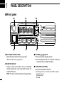
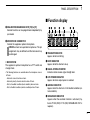
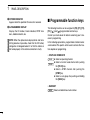
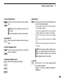
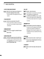
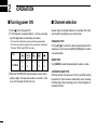
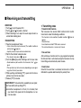
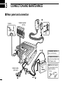
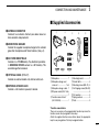
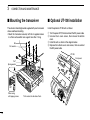
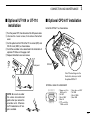
INSTRUCTION MANUAL VHF TRANSCEIVER iF110 UHF TRANSCEIVER iF210 IMPORTANT PRECAUTIONS READ ALL INSTRUCTIONS carefully and com- RWARNING! NEVER connect the transceiver to an AC outlet. This may pose a fire hazard or result in an electric shock. pletely before using the transceiver. SAVE THIS INSTRUCTION MANUAL — This instruction manual contains important operating instructions for the IC-F110 VHF TRANSCEIVER and IC-F210 UHF TRANSCEIVER. EXPLICIT DEFINITIONS WORD DEFINITION RWARNING Personal injury, fire hazard or electric shock may occur. CAUTION NOTE Equipment damage may occur. If disregarded, inconvenience only. No risk of personal injury, fire or electric shock. RWARNING! NEVER connect the transceiver to a power source of more than 16 V DC such as a 24 V battery. This connection will ruin the transceiver. RWARNING! NEVER cut the DC power cable between the DC plug and fuse holder. If an incorrect connection is made after cutting, the transceiver might be damaged. RWARNING! NEVER place the transceiver where normal operation of the vehicle may be hindered or where it could cause bodily injury. CAUTION! NEVER allow children to touch the transceiver. CAUTION! NEVER snow or any liquids. Icom, Icom Inc. and the Icom logo are registered trademarks of Icom Incorporated (Japan) in Japan, the United states, the United Kingdom, Germany, France, Spain, Russia and/or other countries. expose the transceiver to rain, TABLE OF CONTENTS USE the supplied microphone only. Other microphones have different pin assignments and may damage the transceiver. DO NOT use or place the transceiver in areas with temperatures below –25°C or above +55°C, or in areas subject to direct sunlight, such as the dashboard. DO NOT operate the transceiver without running the vehicle’s engine. The vehicle’s battery will quickly run out if the transceiver transmits while the vehicle’s engine OFF. DO NOT place the transceiver in excessively dusty environments. DO NOT place the transceiver against walls. This will obstruct heat dissipation. DO NOT use of chemical agents such as benzine or alcohol when cleaning, as they damage the transceiver surfaces. BE CAREFUL! The transceiver will become hot when operating continuously for long periods. IMPORTANT........................................................................... i EXPLICIT DEFINITIONS........................................................ i PRECAUTIONS...................................................................... i TABLE OF CONTENTS......................................................... ii 1 PANEL DESCRIPTION.................................................1–6 ■ Front panel....................................................................1 ■ Function display............................................................2 ■ Programmable function keys.........................................3 2 OPERATION...............................................................7–10 ■ Turning power ON.........................................................7 ■ Channel selection..........................................................7 ■ Receiving and transmitting............................................8 3 CONNECTION AND MAINTENANCE.....................11–15 ■ Rear panel and connection.........................................11 ■ Supplied Accessories..................................................12 ■ Mounting the transceiver.............................................13 ■ Optional UT-108 installation........................................13 ■ Optional UT-109 or UT-110 installation........................14 ■ Optional OPC-617 installation........................................ 14 ■ Antenna.......................................................................15 ■ Fuse replacement.......................................................15 ■ Cleaning......................................................................15 4 OPTIONS........................................................................16 5 CE.............................................................................17–18 ii 1 PANEL DESCRIPTION ■ Front panel q w y t qAF VOLUME CONTROL KNOB Rotate the knob to adjust the audio output level. • Minimum audio level is pre-programmed. wFUNCTION DISPLAY Displays a variety of information, such as an operating channel number/name, 5-tone code, DTMF numbers and audible condition, etc. NOTE: The above functions depend on pre-programming. e r eUP/DOWN [ ]/[ ] KEYS ➥ Push to select the operating channel. ➥ Can be programmed for one of several functions by your dealer. (Same as [P0] to [P3] keys) rPOWER SWITCH [POWER] Push to turn the power ON and OFF. • The following functions are available at power ON as options: - Automatic scan start - Password prompt - Set mode 1 PANEL DESCRIPTION ■ Function display t DEALER-PROGRAMMABLE KEYS [P0] to [P3] Desired functions can be programmed independently by your dealer. y MICROPHONE CONNECTOR Connect the supplied or optional microphone. NEVER connect non-specified microphones. The pin assignments may be different and the transceiver may be damaged. D MICROPHONE The supplied or optional microphone has a PTT switch and a hanger hook. • The following functions are available when the microphone is on or off hook: - Automatic scan start when on hook. - Automatic priority channel selection when off hook. - Sets to ‘Inaudible’ condition (mute condition) when on hook. - Sets to ‘Audible’ condition (unmute condition) when off hook. q w e r t y u i qTRANSMIT INDICATOR Appears while transmitting. wBUSY INDICATOR Appears while the channel is busy. eSIGNAL STRENGTH METER Indicates relative receive signal strength level. rLOW POWER INDICATOR Appears when low output power is selected. tAUDIBLE INDICATOR Appears when the channel is in the ‘Audible’ condition (unmute condition). ySCRAMBLER INDICATOR Appears when the scrambler function is activated. (Optional UT-109 (#02)/UT-110 (#02) SCRAMBLER UNIT is required.) 1 PANEL DESCRIPTION u2/5TONE INDICATOR Appears when the specified 2/5-tone call is received. ■ Programmable function keys iALPHANUMERIC DISPLAY Displays the CH number, 5-tone indication, DTMF numbers, Audible indication, etc. The following functions can be assigned to [P0], [P1], [P2], [P3], [ ] and [ ] programmable function keys. Consult your Icom dealer for details concerning your transceiver’s programming. In the following explanations, programmable function names are bracketed. The specific switch used to activate the function depends on programming. NOTE: When the alphanumeric display blinks and transmitting becomes impossible, check that the DC battery voltage has not dropped below 8 V or that the antenna is not tuned properly or the antenna connection is faulty. • CH UP AND DOWN KEYS ➥ Select an operating channel. CH UP ➥ Select a transmit code channel after pushing CH DN the [TX CH] key. ➥ S elect a DTMF channel after pushing the [DTMF] key. ➥ Select a scan group after pushing and holding the [SCAN] key. • BANK KEY Select and determine a bank number. BANK 3 PANEL DESCRIPTION • SCAN START/STOP KEY Push this key to start scanning; and push again to stop. NOTE: Place the microphone on hook to start scanning. Take the microphone off hook to stop scanning. • SCAN TAG KEY Adds or deletes the selected channel to the scan TAG group. • PRIORITY CHANNEL KEYS Push these keys to select priority A or priority B channel, respectively. • OPERATING CHANNEL KEYS Select an operating channel directly. MR-1 MR-2 MR-3 1 • MONITOR KEY Activates one of (or two of) the following functions MONI on each channel independently: • Push and hold the key to unmute the channel (audio is emitted; ‘Audible’ condition). • Push the key to toggle between the mute and unmute conditions (toggles between ‘Audible’ and ‘Inaudible’). • Push the key to mute the channel (sets to ‘Inaudible’ only). • Push the key to unmute the channel (sets to ‘Audible’ only). • Push the key after communication is finished to send a ‘reset code’. OTE: The unmute condition (‘Audible’ condiN tion) may automatically return to the mute condition (‘Inaudible’ condition) after a specified period depending on the pre-setting. • LOCK KEY Push this key for 1 sec. to lock all programmable LOCK keys except the following: • [ CALL] (incl. [CAL A] and [CAL B]), [ MONI] and [EMER] keys. MR-4 4 1 PANEL DESCRIPTION • OUTPUT POWER SELECTION KEYS Select the transmit output power temporarily, or permanently, depending on the pre-setting. • Contact your dealer for the output power level for each selection. • TALK AROUND KEY Turns the talk around function ON and OFF. TA • The talk around function equalizes the transmit frequency to the receive frequency for mobile-to-mobile communication. • WIDE/NARROW KEY Push this key to toggle the bandwidth between wide or narrow. • DTMF AUTODIAL KEY Push this key to display the text of the DTMF chanDTMF nel number and set the desired channel number via the [ ]/[ ] key. Then, push this key again to transmit a specified DTMF code. • CALL KEY Transmit a 2-tone, 5-tone code. • Call transmission is necessary before you call another station depending on your signaling system. • The [CAL A] and/or [CAL B] keys may be available when your system employs selective ‘Individual/Group’ calls. Contact your dealer about which call is assigned to each key. • EMERGENCY KEY Push and hold the key to transmit an emergency call. EMER • If you want to cancel the emergency call, push and hold (or push) the key again before transmitting the call. • Depending on the pre-setting, the emergency call is transmitted one time only, or repeatedly, until receiving a control code. • HOOK SCAN When the Hook Scan function is turned ON, push this key to stop scanning temporarily. Push this key again to re-start scanning. • TX CODE KEY Select a transmit 5-tone code (station code) chanTX CH nel. 5 PANEL DESCRIPTION • SCRAMBLER KEY ➥ Push and hold to turn the voice scrambler funcSCRM tion ON. ➥ Push this key to turn the voice scrambler function OFF. NOTE: • The optional UT-109 (#02) or UT-110 (#02) voice scrambler unit is required. - UT-109: N on-rolling type. 32 codes are available. - UT-110: R olling type. Provides higher communication security. 1020 (4 groups × 255) codes are available. • This transceiver requires version #02 of these units. Do not install version #01, as they are not compatible. • Some PC board modifications are required when installing UT-109 or UT-110. Please refer to ‘Optional UT-109 or UT-110 installation’. (p. 14) • Please contact your dealer for details. 1 • USER SET MODE KEY Changes the contents of the items in the User Set SET mode. Please refer to p. 10. • Push and hold this key for 1 sec. to enter set mode. Push this key again momentarily to select the desired item. Push [ ]/[ ] to set the desired level/condition. Push and hold this key again to exit set mode. • User set mode also available via the ‘Power ON function’. 2 OPERATION ■ Turning power ON ■ Channel selection qPush [ ] to turn the power ON. wIf the transceiver is programmed for a start up passcode, input the digit codes as directed by your dealer. Several types of channel selection are available. The methods may differ according to your system setup. NON-BANK TYPE: Push [ ]/[ ] to select the desired operating channel in sequence; or, push one of the [CH 1] to [CH 4] keys to select a channel directly. • The keys in the table below can be used for password input: • The transceiver detects numbers in the same block as identical. Therefore “01234” and “56789” are same. KEY NUMBER 0 5 1 6 2 7 3 4 8 9 e When the “PASSWORD” indication does not clear after inputting 4 digits, the input code number is incorrect. In this case, turn the power off and start over. BANK-TYPE: Push [BANK] to select the desired bank number or name. AUTOMATIC SCAN TYPE: Channel setting is not necessary for this type. When turning the power ON, the transceiver automatically starts scanning. Scanning stops when receiving a call or when taking the microphone off hook. OPERATION 2 ■ Receiving and transmitting RECEIVING: q Push [ ] to turn the power ON. w Push [ ] or [ ] to select a channel. e When receiving a call, adjust the audio output level to a comfortable listening level. TRANSMITTING: q Take the microphone off hook. • 2-tone, 5-tone mute may be released. (The ‘audible’ condition is selected and “ ” appears.) • A priority channel may be selected automatically. w Wait for the channel to become clear. • The channel is busy when “ ” appears. e Push the [CALL] key when initiating a call from your side. • Coded audio may be heard from the transceiver, then “ ” appears. • This operation may not be necessary depending on your signaling system. Contact your dealer. r While pushing and holding [PTT], speak into the microphone at your normal voice level. t Release [PTT] to receive. D Transmitting notes • Transmit inhibit function The transceiver has several inhibit functions which restrict transmission under the following conditions: - The channel is in mute condition (‘Inaudible’ condition; “ appear). - Channel is busy. - A matched/un-matched CTCSS code is received. - The selected channel is a ‘receive only’ channel. ” does not • Time-out timer After continuous transmission for a pre-programmed period, the time-out timer is activated causing the transceiver to stop transmitting and automatically select receive. • Penalty timer Once the time-out timer is activated, transmission is further inhibited for a period determined by the penalty timer. IMPORTANT!: To maximize the readability of your signal; ➥ Pause briefly after pushing [PTT]. ➥ Hold the microphone 5 to 10 cm (2 to 4 inches) from your mouth, then speak into the microphone at a normal voice level. 8 2 OPERATION D TX code channel selection D DTMF transmission If the transceiver has a [TX CH] key, the display can be toggled between the operating channel number (or name) and TX code channel number (or name). When the TX code channel number (or name) is displayed, the [ ]/[ ] keys select the TX code channel. If the transceiver has a [DTMF] key, the automatic DTMF transmission function is available. Up to 7 DTMF channels may be available. To select a TX channel: qPush [TX CH]—a TX code channel appears. wPush [ ]/[ ] to select the desired TX code channel. eAfter selecting, push [TX CH] to set. • Returns to the stand-by mode. rPush [CALL] to transmit the selected TX code. D TX code number selection If the transceiver has a [TX CH] key, TX code contents can be changed within the allowable digits. To select a TX code: qPush [TX CH]—a TX code number appears and the first digit blinks. wPush [ ]/[ ] to select the desired number of the blinking digit. ePush [TX CH] to enter the selected number and the next digit will start blinking automatically. rRepeat step w and e to input all allowed digits. tPush [CALL] to transmit the selected TX code. To transmit a DTMF code: q Push [DTMF]—a DTMF code channel appears. w Push [ ]/[ ] to select the desired DTMF channel. e Push and hold [DTMF] to transmit the DTMF code on the selected DTMF channel. D Scrambler function The UT-109 (#02) or UT-110 (#02) optional voice scrambler unit provides high performance private communication between stations with the same scrambler codes. To turn the scrambler function ON and OFF: q Push and hold [SCRM] to turn the scrambler function ON. w Push [SCRM] to turn the function OFF. OPERATION 2 D User set mode User set mode is accessed at power ON and allows you to set seldom-changed settings. In this case you can “customize” transceiver operation to suit your preferences and operating style. Entering the user set mode: q While pushing and holding [ ] and [ ], push [POWER] to enter user set mode ON, allowing you to set seldomchanged settings. w Push and hold [P0] to select the appropriate item. Then, push [ ] or [ ] to set the desired level/mode. - Available set mode functions; • Backlight : OFF, Dim, Auto or ON • Beep : OFF or ON • SQL Level : 0 to 255 • AF Min level : 0 to 255 e Push [POWER] (or push and hold [P0]) again to exit set mode. User set mode is also available via a programmable key. Please refer to p. 6 [SET] section. [SET] is allowed for the quick item selection. Set “Enable” for the often used items with the CS-F100 cloning software. 10 3 CONNECTION AND MAINTENANCE ■ Rear panel and connection w Optional speaker (SP-22) Antenna red: q + R WARNING! NEVER remove the fuse-holder from the DC power cable. t 12V Battery Optional cable (OPC-617) e r 11 R WARNING! NEVER connect to a 24 V battery. black: NOTE: Use the terminals as shown below for the cable connections. Crimp Solder CONNECTION AND MAINTENANCE 3 ■ Supplied Accessories qANTENNA CONNECTOR Connects to an antenna. Contact your dealer about antenna selection and placement. wMICROPHONE HANGER Connect the supplied microphone hanger to the vehicle’s ground for microphone on/off hook functions. (See p. 2) eDC POWER RECEPTACLE Connects to a 12 V DC battery. Pay attention to polarities. R WARNING! NEVER connect to a 24 V battery. This could damage the transceiver. rOPTIONAL CABLE (OPC-617) Connect an external modem unit, dimmer control, etc. tEXTERNAL SPEAKER JACK Connect a 4–8 ø external speaker, if desired. q w e y r t u i o !0 !1 !2 q Microphone ....................... 1 w Microphone hanger and screw set . .................... 1 set e Microphone hanger cable .. 1 r DC power cable (OPC-1194A) .............................................1 t Function name stickers* (KEY STICKER) . ................... 1 y Mounting bracket ............... 1 u Bracket bolts ...................... 4 i Mounting screws (M5×12) . 4 o Self-tapping screws (M5×20) ............................................ 4 !0 Flat washers ...................... 4 !1 Spring washers .................. 4 !2 Nuts ................................... 4 *Function name stickers There are no names on the programmable function keys since the functions can be freely assigned to these keys. Attach the supplied function name stickers above the appropriate keys for easy recognition of that key’s assigned function. 12 3 CONNECTION AND MAINTENANCE ■ Mounting the transceiver ■ Optional UT-108 installation The universal mounting bracket supplied with your transceiver allows overhead mounting. • Mount the transceiver securely with the 4 supplied screws to a thick surface which can support more than 1.5 kg. Install the optional UT-108 unit as follows: Nut Flat washer q Turn the power OFF, then disconnect the DC power cable. wUnscrew the 4 cover screws, then remove the bottom cover. eInstall the unit as shown in the diagram below. rReplace the bottom cover and screws, then re-connect the DC power cable. UT-108 Front panel Felt* Spring washer Felt* When using self-tapping screws 13 *Felts reduce the vibration effects. CONNECTION AND MAINTENANCE ■ Optional UT-109 or UT-110 installation 3 ■ Optional OPC-617 installation Install the OPC-617 as shown below. q Turn the power OFF, then disconnect the DC power cable. w Unscrew the 4 cover screws, then remove the bottom cover. e Cut the pattern on the PCB at the TX mic circuit (MIC) and RX AF circuit (DISC) as shown below. r Install the scrambler unit as described in the installation of optional UT-108 as on the page at left. t Replace the bottom cover and screws. DISC MIC Front panel OPC-617 Cut off the bushing as in the illustration, when you install the optional OPC-617. OPTIONAL CABLE PIN ASSIGNMENT trewq NOTE: Be sure to re-solder the above disconnected points when you remove the scrambler units. Otherwise no TX modulation or AF output is available. oiuy q Dmmer cont. IN or IGSW cont. IN w AF OUT e Det. AF OUT r Mod. IN t PTT control IN or FTSW control IN y Horn drve cont. OUT u AF GND i Det. AF GND o Mod. GND 14 3 CONNECTION AND MAINTENANCE ■ Antenna A key element in the performance of any communication system is an antenna. Contact your dealer about antennas and the best places to mount them. ■ Fuse replacement A fuse is installed in the supplied DC power cable. If a fuse blows or the transceiver stops functioning, track down the source of the problem if possible, and replace the damaged fuse with a new rated one. ❑ Fuse rating: 10 A ■ Cleaning If the transceiver becomes dusty or dirty, wipe it clean with a soft, dry cloth. 15 AVOID the use of solvents such as benzene or alcohol, as they may damage the transceiver surfaces. OPTIONS • SP-22 external speaker Compact and easy-to-install. Input impedance : 4 ø Max. input power: 5 W • HM-152/HM-152T/HM-148G/HM-148T hand microphones HM-152 : Hand microphone HM-152T : DTMF microphone HM-148G: Self ground heavy duty microphone HM-148T : Self ground heavy duty DTMF microphone The 10-keypad of this microphone can be used for the DTMF code transmission only. 4 Approved Icom optional equipment is designed for optimal performance when used with an Icom transceiver. Icom is not responsible for the destruction or damage to an Icom transceiver in the event the Icom transceiver is used with equipment that is not manufactured or approved by Icom. Some options may not be available in some countries. Please ask your dealer for details. • SM-25 desktop microphone • UT-108 dtmf decoder unit Provides pager and code squelch capabilities. • UT-109/UT-110 (#02) scrambler units UT-109: Non-rolling type (max. 32 codes) UT-110: Rolling type (max. 1020 codes) • OPC-617 acc cable Allows you to connect to an external terminal. 16 5 CE DECLARATION OF CONFORMITY We Icom Inc. Japan 0168 1-1-32, Kamiminami, Hirano-ku Osaka 547-0003, Japan Declare on our sole responsibility that this equipment complies with the essential requirements of the Radio and Telecommunications Terminal Equipment Directive, 1999/5/EC, and that any applicable Essential Test Suite measurements have been performed. Kind of equipment: VHF TRANSCEIVER Type-designation: iC-f110 Version (where applicable): Düsseldorf 18th Nov. 2002 Place and date of issue Authorized representative name 136–174 MHz 12.5 kHz/ 25 kHz 136–174 MHz 12.5 kHz/ 20 kHz This compliance is based on conformity with the following harmonised standards, specifications or documents: i) ii) iii) iv) v) EN 301 489-1 (August 2000) EN 301 489-5 (August 2000) EN 60 950 (August 1992 +A11) EN 300 086-2 (March 2001) EN 300 219-2 (March 2001) Signature vii) viii) CE Versions of the IC-F110/IC-F210 which display the “CE” symbol on the serial number label, comply with the essential requirements of the European Radio and Telecommunication Terminal Directive 1999/5/EC. 17 This warning symbol indicates that this equipment operates in non-harmonised frequency bands and/ or may be subject to licensing conditions in the country of use. Be sure to check that you have the correct version of this radio or the correct programming of this radio, to comply with national licensing requirement. CE 5 DECLARATION OF CONFORMITY We Icom Inc. Japan 0168 1-1-32, Kamiminami, Hirano-ku Osaka 547-0003, Japan Declare on our sole responsibility that this equipment complies with the essential requirements of the Radio and Telecommunications Terminal Equipment Directive, 1999/5/EC, and that any applicable Essential Test Suite measurements have been performed. Kind of equipment: UHF TRANSCEIVER Type-designation: iC-f210 Version (where applicable): 440–490 MHz 12.5 kHz/ 25 kHz 440–490 MHz 12.5 kHz/ 20 kHz 400–430 MHz 12.5 kHz/ 25 kHz Düsseldorf 15th Jan. 2003 Place and date of issue Authorized representative name This compliance is based on conformity with the following harmonised standards, specifications or documents: i) ii) iii) iv) v) EN 301 489-1 (August 2000) EN 301 489-5 (August 2000) EN 60950 (August 1992 +A11) EN 300 086-2 (March 2001) EN 300 219-2 (March 2001) Signature vii) viii) About e-marking: Detailed installation notes for Icom mobile transceivers to be fitted into vehicles are available. Please contact your Icom dealer or distributor. 18 MEMO MEMO < Intended Country of Use > GER AUT GBR IRL NOR A-6234H-1EU-e Printed in Japan © 2002–2009 Icom Inc. FRA NED BEL LUX ESP POR ITA GRE SWE DEN FIN SUI 1-1-32 Kamiminami, Hirano-ku, Osaka 547-0003, Japan