1
OS-9 Technical
User Manual
Copyright and Revision
History
Copyright 1991 Microware Systems Corporation. All Rights Reserved.
Reproduction of this document, in part or whole, by any means, electrical,
mechanical, magnetic, optical, chemical, manual, or otherwise is prohibited, without written permission from Microware Systems Corporation.
Publication Editors: Walden Miller, Kathleen Flood, Debbie Baier
Contributing Writers: Warren Brown, Richard Yeates
Revision: J
Publication date: March 1991
Product Number: OST68NA68MO
Disclaimer
The software described in this document is intended to be used on a single
computer system. Microware expressly prohibits any reproduction of the
software on tape, disk or any other medium except for backup purposes.
Distribution of this software, in part or whole, to any other party or on any
other system may constitute copyright infringements and misappropriation
of trade secrets and confidential processes which are the property of
Microware and/or other parties. Unauthorized distribution of software may
cause damages far in excess of the value of the copies involved.
For additional copies of this software and/or documentation, or if you have
questions concerning the above notice, the documentation and/or software,
please contact your OS-9 supplier.
Trademarks
Microware, OS-9, and RAVE are registered trademarks of Microware
Systems Corporation.
Microware Systems Corporation • 1900 N.W. 114th Street
Des Moines, Iowa 50325-7077 • Phone: 515/224-1929
Preface
Introduction
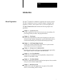
Manual Organization
The OS-9 Technical User Manual is organized into two main sections:
The OS-9 Technical Overview is covered in chapters 1 through 7 and
Appendix A, B and C; OS-9 System Calls is covered in Appendix D.
The OS-9 Technical Overview contains the following chapters and
appendices:
Chapter 1 – System Overview
Provides a general overview of OS-9’s four levels of modularity, I/O
processing, memory modules, and program modules.
Chapter 2 – The Kernel
Outlines the responsibilities of the kernel. Explains user and system
state processing, memory management, system initialization, process
creation and scheduling, and exception and interrupt processing.
Chapter 3 – OS-9 Input/Output System
Explains the software components of the OS-9 I/O system and the
relationships between those components.
Chapter 4 – Interprocess Communications
Describes the five forms of interprocess communication supported by
OS-9: signals, alarms, events, pipes, and data modules.
Chapter 5 – User Trap Handlers
Explains how to install and execute trap handlers, and provides an
example of trap handler coding.
Chapter 6 – The Math Module
Discusses math module functions, and lists descriptions of the assembler
calls you can use with the math module.
Chapter 7 – RBF File System
Explains OS-9’s disk file organization, raw physical I/O on RBF
devices, record locking, and file security.
i
Preface
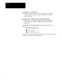
Appendix A – Example Code
Contains example code that you can use as a guide when creating
your own modules. Provides examples of RBF, SCF, and SBF
device descriptors.
Appendix B – Path Descriptors and Device Descriptors
Includes the device descriptor initialization table definitions and
path descriptor option tables for RBF, SCF, SBF, and PIPEMAN
type devices.
Appendix C – OS-9 System Calls contains descriptions for the
following types of system calls:
User-State System Calls
I/O System Calls
System-State System Calls
The OS-9 Technical User Manual is designed for you to use in conjunction
with the OS-9 Technical I/O User Manual.
ii
Table of Contents
OS-9 Technical User Manual
System Overview
Chapter 1
System Modularity . . . . . . . . . . . . . . . . . . . . . . . . . . . . . . . . . . . . . . . . . .
I/O Overview . . . . . . . . . . . . . . . . . . . . . . . . . . . . . . . . . . . . . . . . . . . . . . .
The Kernel
Chapter 2
Responsibilities of the Kernel . . . . . . . . . . . . . . . . . . . . . . . . . . . . . . . . . .
System Call Overview . . . . . . . . . . . . . . . . . . . . . . . . . . . . . . . . . . . . . . . .
Memory Management . . . . . . . . . . . . . . . . . . . . . . . . . . . . . . . . . . . . . . . .
System Initialization . . . . . . . . . . . . . . . . . . . . . . . . . . . . . . . . . . . . . . . . .
Process Creation . . . . . . . . . . . . . . . . . . . . . . . . . . . . . . . . . . . . . . . . . . . .
Process Scheduling . . . . . . . . . . . . . . . . . . . . . . . . . . . . . . . . . . . . . . . . . .
Exception and Interrupt Processing . . . . . . . . . . . . . . . . . . . . . . . . . . . . . .
OS-9 Input/Output System
1-1
1-3
2-1
2-1
2-5
2-12
2-18
2-22
2-24
Chapter 3
The OS-9 Unified Input/Output System . . . . . . . . . . . . . . . . . . . . . . . . . .
The Kernel and I/O . . . . . . . . . . . . . . . . . . . . . . . . . . . . . . . . . . . . . . . . . .
File Managers . . . . . . . . . . . . . . . . . . . . . . . . . . . . . . . . . . . . . . . . . . . . . .
Device Driver Modules . . . . . . . . . . . . . . . . . . . . . . . . . . . . . . . . . . . . . . .
Interprocess
Communications
Chapter 4
User Trap Handlers
Chapter 5
Signals . . . . . . . . . . . . . . . . . . . . . . . . . . . . . . . . . . . . . . . . . . . . . . . . . . . .
Alarms . . . . . . . . . . . . . . . . . . . . . . . . . . . . . . . . . . . . . . . . . . . . . . . . . . . .
Events . . . . . . . . . . . . . . . . . . . . . . . . . . . . . . . . . . . . . . . . . . . . . . . . . . . .
Pipes . . . . . . . . . . . . . . . . . . . . . . . . . . . . . . . . . . . . . . . . . . . . . . . . . . . . .
Data Modules . . . . . . . . . . . . . . . . . . . . . . . . . . . . . . . . . . . . . . . . . . . . . . .
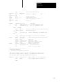
Trap Handlers . . . . . . . . . . . . . . . . . . . . . . . . . . . . . . . . . . . . . . . . . . . . . .
Installing and Executing Trap Handlers . . . . . . . . . . . . . . . . . . . . . . . . . .
OS-9 and tcall: Equivalent Assembly Language Syntax . . . . . . . . . . . . . .
Calling a Trap Handler . . . . . . . . . . . . . . . . . . . . . . . . . . . . . . . . . . . . . . .
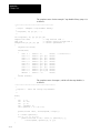
An Example Trap Handler . . . . . . . . . . . . . . . . . . . . . . . . . . . . . . . . . . . . .
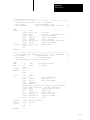
Trace of Example Two Using the Example Trap Handler . . . . . . . . . . . .
3-1
3-2
3-6
3-10
4-1
4-3
4-6
4-8
4-13
5-1
5-2
5-2
5-3
5-5
5-8
I
Table of Contents
OS-9 Technical User Manual
The Math Module
Chapter 6
The Standard Function Library Module . . . . . . . . . . . . . . . . . . . . . . . . . .
Calling Standard Function Module Routines . . . . . . . . . . . . . . . . . . . . . .
Data Formats . . . . . . . . . . . . . . . . . . . . . . . . . . . . . . . . . . . . . . . . . . . . . . .
The Math Module . . . . . . . . . . . . . . . . . . . . . . . . . . . . . . . . . . . . . . . . . . .
T$Acs . . . . . . . . . . . . . . . . . . . . . . . . . . . . . . . . . . . . . . . . . . . . . . . . . . . .
T$Asn . . . . . . . . . . . . . . . . . . . . . . . . . . . . . . . . . . . . . . . . . . . . . . . . . . . .
T$Atn . . . . . . . . . . . . . . . . . . . . . . . . . . . . . . . . . . . . . . . . . . . . . . . . . . . . .
T$AtoD . . . . . . . . . . . . . . . . . . . . . . . . . . . . . . . . . . . . . . . . . . . . . . . . . . .
T$AtoF . . . . . . . . . . . . . . . . . . . . . . . . . . . . . . . . . . . . . . . . . . . . . . . . . . .
T$AtoL . . . . . . . . . . . . . . . . . . . . . . . . . . . . . . . . . . . . . . . . . . . . . . . . . . .
T$AtoN . . . . . . . . . . . . . . . . . . . . . . . . . . . . . . . . . . . . . . . . . . . . . . . . . . .
T$AtoU . . . . . . . . . . . . . . . . . . . . . . . . . . . . . . . . . . . . . . . . . . . . . . . . . . .
T$Cos . . . . . . . . . . . . . . . . . . . . . . . . . . . . . . . . . . . . . . . . . . . . . . . . . . . .
T$DAdd . . . . . . . . . . . . . . . . . . . . . . . . . . . . . . . . . . . . . . . . . . . . . . . . . . .
T$DCmp . . . . . . . . . . . . . . . . . . . . . . . . . . . . . . . . . . . . . . . . . . . . . . . . . .
T$DDec . . . . . . . . . . . . . . . . . . . . . . . . . . . . . . . . . . . . . . . . . . . . . . . . . . .
T$DDiv . . . . . . . . . . . . . . . . . . . . . . . . . . . . . . . . . . . . . . . . . . . . . . . . . . .
T$DInc . . . . . . . . . . . . . . . . . . . . . . . . . . . . . . . . . . . . . . . . . . . . . . . . . . . .
T$DInt . . . . . . . . . . . . . . . . . . . . . . . . . . . . . . . . . . . . . . . . . . . . . . . . . . . .
T$DMul . . . . . . . . . . . . . . . . . . . . . . . . . . . . . . . . . . . . . . . . . . . . . . . . . . .
T$DNeg . . . . . . . . . . . . . . . . . . . . . . . . . . . . . . . . . . . . . . . . . . . . . . . . . . .
T$DNrm . . . . . . . . . . . . . . . . . . . . . . . . . . . . . . . . . . . . . . . . . . . . . . . . . .
T$DSub . . . . . . . . . . . . . . . . . . . . . . . . . . . . . . . . . . . . . . . . . . . . . . . . . . .
T$DtoA . . . . . . . . . . . . . . . . . . . . . . . . . . . . . . . . . . . . . . . . . . . . . . . . . . .
T$DtoF . . . . . . . . . . . . . . . . . . . . . . . . . . . . . . . . . . . . . . . . . . . . . . . . . . .
T$DtoL . . . . . . . . . . . . . . . . . . . . . . . . . . . . . . . . . . . . . . . . . . . . . . . . . . .
T$DtoU . . . . . . . . . . . . . . . . . . . . . . . . . . . . . . . . . . . . . . . . . . . . . . . . . . .
T$DTrn . . . . . . . . . . . . . . . . . . . . . . . . . . . . . . . . . . . . . . . . . . . . . . . . . . .
T$Exp . . . . . . . . . . . . . . . . . . . . . . . . . . . . . . . . . . . . . . . . . . . . . . . . . . . .
T$FAdd . . . . . . . . . . . . . . . . . . . . . . . . . . . . . . . . . . . . . . . . . . . . . . . . . . .
T$FCmp . . . . . . . . . . . . . . . . . . . . . . . . . . . . . . . . . . . . . . . . . . . . . . . . . . .
T$FDec . . . . . . . . . . . . . . . . . . . . . . . . . . . . . . . . . . . . . . . . . . . . . . . . . . .
T$FDiv . . . . . . . . . . . . . . . . . . . . . . . . . . . . . . . . . . . . . . . . . . . . . . . . . . .
T$FInc . . . . . . . . . . . . . . . . . . . . . . . . . . . . . . . . . . . . . . . . . . . . . . . . . . . .
T$FInt . . . . . . . . . . . . . . . . . . . . . . . . . . . . . . . . . . . . . . . . . . . . . . . . . . . .
T$FMul . . . . . . . . . . . . . . . . . . . . . . . . . . . . . . . . . . . . . . . . . . . . . . . . . . .
T$FNeg . . . . . . . . . . . . . . . . . . . . . . . . . . . . . . . . . . . . . . . . . . . . . . . . . . .
T$FSub . . . . . . . . . . . . . . . . . . . . . . . . . . . . . . . . . . . . . . . . . . . . . . . . . . .
T$FtoA . . . . . . . . . . . . . . . . . . . . . . . . . . . . . . . . . . . . . . . . . . . . . . . . . . .
T$FtoD . . . . . . . . . . . . . . . . . . . . . . . . . . . . . . . . . . . . . . . . . . . . . . . . . . .
T$FtoL . . . . . . . . . . . . . . . . . . . . . . . . . . . . . . . . . . . . . . . . . . . . . . . . . . . .
T$FtoU . . . . . . . . . . . . . . . . . . . . . . . . . . . . . . . . . . . . . . . . . . . . . . . . . . .
T$FTrn . . . . . . . . . . . . . . . . . . . . . . . . . . . . . . . . . . . . . . . . . . . . . . . . . . . .
T$LDiv . . . . . . . . . . . . . . . . . . . . . . . . . . . . . . . . . . . . . . . . . . . . . . . . . . .
II
6-1
6-2
6-2
6-3
6-5
6-6
6-7
6-8
6-9
6-10
6-11
6-12
6-13
6-14
6-15
6-16
6-17
6-18
6-19
6-20
6-21
6-22
6-23
6-24
6-25
6-26
6-27
6-28
6-29
6-30
6-31
6-32
6-33
6-34
6-35
6-36
6-37
6-38
6-39
6-40
6-41
6-42
6-43
6-44
Table of Contents
OS-9 Technical User Manual
The Math Module
Chapter 6 Continued
T$LMod . . . . . . . . . . . . . . . . . . . . . . . . . . . . . . . . . . . . . . . . . . . . . . . . . . .
T$LMul . . . . . . . . . . . . . . . . . . . . . . . . . . . . . . . . . . . . . . . . . . . . . . . . . . .
T$Log . . . . . . . . . . . . . . . . . . . . . . . . . . . . . . . . . . . . . . . . . . . . . . . . . . . .
T$Log10 . . . . . . . . . . . . . . . . . . . . . . . . . . . . . . . . . . . . . . . . . . . . . . . . . .
T$LtoA . . . . . . . . . . . . . . . . . . . . . . . . . . . . . . . . . . . . . . . . . . . . . . . . . . .
T$LtoD . . . . . . . . . . . . . . . . . . . . . . . . . . . . . . . . . . . . . . . . . . . . . . . . . . .
T$LtoF . . . . . . . . . . . . . . . . . . . . . . . . . . . . . . . . . . . . . . . . . . . . . . . . . . . .
T$Power . . . . . . . . . . . . . . . . . . . . . . . . . . . . . . . . . . . . . . . . . . . . . . . . . .
T$Sin . . . . . . . . . . . . . . . . . . . . . . . . . . . . . . . . . . . . . . . . . . . . . . . . . . . . .
T$Sqrt . . . . . . . . . . . . . . . . . . . . . . . . . . . . . . . . . . . . . . . . . . . . . . . . . . . .
T$Tan . . . . . . . . . . . . . . . . . . . . . . . . . . . . . . . . . . . . . . . . . . . . . . . . . . . . .
T$UDiv . . . . . . . . . . . . . . . . . . . . . . . . . . . . . . . . . . . . . . . . . . . . . . . . . . .
T$UMod . . . . . . . . . . . . . . . . . . . . . . . . . . . . . . . . . . . . . . . . . . . . . . . . . .
T$UMul . . . . . . . . . . . . . . . . . . . . . . . . . . . . . . . . . . . . . . . . . . . . . . . . . . .
T$UtoA . . . . . . . . . . . . . . . . . . . . . . . . . . . . . . . . . . . . . . . . . . . . . . . . . . .
T$UtoD . . . . . . . . . . . . . . . . . . . . . . . . . . . . . . . . . . . . . . . . . . . . . . . . . . .
T$UtoF . . . . . . . . . . . . . . . . . . . . . . . . . . . . . . . . . . . . . . . . . . . . . . . . . . .
OS-9 File System
Chapter 7
Disk File Organization . . . . . . . . . . . . . . . . . . . . . . . . . . . . . . . . . . . . . . . .
Raw Physical I/O on RBF Devices . . . . . . . . . . . . . . . . . . . . . . . . . . . . . .
Record Locking . . . . . . . . . . . . . . . . . . . . . . . . . . . . . . . . . . . . . . . . . . . . .
Record Locking Details for I/O Functions . . . . . . . . . . . . . . . . . . . . . . . .
File Security . . . . . . . . . . . . . . . . . . . . . . . . . . . . . . . . . . . . . . . . . . . . . . . .
Example Code
6-45
6-46
6-47
6-48
6-49
6-50
6-51
6-52
6-53
6-54
6-55
6-56
6-57
6-58
6-59
6-60
6-61
7-1
7-6
7-7
7-9
7-10
Appendix A
Introduction . . . . . . . . . . . . . . . . . . . . . . . . . . . . . . . . . . . . . . . . . . . . . . . .
Init Module . . . . . . . . . . . . . . . . . . . . . . . . . . . . . . . . . . . . . . . . . . . . . . . .
Sysgo Module . . . . . . . . . . . . . . . . . . . . . . . . . . . . . . . . . . . . . . . . . . . . . .
Signals: Example Program . . . . . . . . . . . . . . . . . . . . . . . . . . . . . . . . . . . .
Alarms: Example Program . . . . . . . . . . . . . . . . . . . . . . . . . . . . . . . . . . . .
Events: Example Program . . . . . . . . . . . . . . . . . . . . . . . . . . . . . . . . . . . . .
C Trap Handler . . . . . . . . . . . . . . . . . . . . . . . . . . . . . . . . . . . . . . . . . . . . .
RBF Device Descriptor . . . . . . . . . . . . . . . . . . . . . . . . . . . . . . . . . . . . . . .
SCF Device Descriptor . . . . . . . . . . . . . . . . . . . . . . . . . . . . . . . . . . . . . . .
SBF Device Descriptor . . . . . . . . . . . . . . . . . . . . . . . . . . . . . . . . . . . . . . .
A-1
A-1
A-5
A-7
A-9
A-11
A-13
A-18
A-23
A-25
III
Table of Contents
OS-9 Technical User Manual
Path Descriptors and Device
Descriptors
Appendix B
OS-9 System Calls
Appendix C
Introduction . . . . . . . . . . . . . . . . . . . . . . . . . . . . . . . . . . . . . . . . . . . . . . . .
RBF Device Descriptor Modules . . . . . . . . . . . . . . . . . . . . . . . . . . . . . . .
RBF Definitions of the Path Descriptor . . . . . . . . . . . . . . . . . . . . . . . . . .
SCF Device Descriptor Modules . . . . . . . . . . . . . . . . . . . . . . . . . . . . . . . .
SCF Definitions of the Path Descriptor . . . . . . . . . . . . . . . . . . . . . . . . . . .
SBF Device Descriptor Modules . . . . . . . . . . . . . . . . . . . . . . . . . . . . . . . .
SBF Definitions of the Path Descriptor . . . . . . . . . . . . . . . . . . . . . . . . . . .
Pipeman Definitions of the Path Descriptor . . . . . . . . . . . . . . . . . . . . . . .
Introduction
OS-9 System Call Descriptions . . . . . . . . . . . . . . . . . . . . . . . . . . . . . . . . .
User-state System Calls
F$Alarm . . . . . . . . . . . . . . . . . . . . . . . . . . . . . . . . . . . . . . . . . . . . . . . . . . .
A$Delete . . . . . . . . . . . . . . . . . . . . . . . . . . . . . . . . . . . . . . . . . . . . . . . . . .
A$Set . . . . . . . . . . . . . . . . . . . . . . . . . . . . . . . . . . . . . . . . . . . . . . . . . . . . .
A$Cycle . . . . . . . . . . . . . . . . . . . . . . . . . . . . . . . . . . . . . . . . . . . . . . . . . . .
A$AtDate . . . . . . . . . . . . . . . . . . . . . . . . . . . . . . . . . . . . . . . . . . . . . . . . . .
A$AtJul . . . . . . . . . . . . . . . . . . . . . . . . . . . . . . . . . . . . . . . . . . . . . . . . . . .
F$AllBit . . . . . . . . . . . . . . . . . . . . . . . . . . . . . . . . . . . . . . . . . . . . . . . . . . .
F$CCtl . . . . . . . . . . . . . . . . . . . . . . . . . . . . . . . . . . . . . . . . . . . . . . . . . . . .
F$Chain . . . . . . . . . . . . . . . . . . . . . . . . . . . . . . . . . . . . . . . . . . . . . . . . . . .
F$CmpNam . . . . . . . . . . . . . . . . . . . . . . . . . . . . . . . . . . . . . . . . . . . . . . . .
F$CpyMem . . . . . . . . . . . . . . . . . . . . . . . . . . . . . . . . . . . . . . . . . . . . . . . .
F$CRC . . . . . . . . . . . . . . . . . . . . . . . . . . . . . . . . . . . . . . . . . . . . . . . . . . . .
F$DatMod . . . . . . . . . . . . . . . . . . . . . . . . . . . . . . . . . . . . . . . . . . . . . . . . .
F$DelBit . . . . . . . . . . . . . . . . . . . . . . . . . . . . . . . . . . . . . . . . . . . . . . . . . .
F$DExec . . . . . . . . . . . . . . . . . . . . . . . . . . . . . . . . . . . . . . . . . . . . . . . . . .
F$DExit . . . . . . . . . . . . . . . . . . . . . . . . . . . . . . . . . . . . . . . . . . . . . . . . . . .
F$DFork . . . . . . . . . . . . . . . . . . . . . . . . . . . . . . . . . . . . . . . . . . . . . . . . . .
F$Event . . . . . . . . . . . . . . . . . . . . . . . . . . . . . . . . . . . . . . . . . . . . . . . . . . .
Ev$Link . . . . . . . . . . . . . . . . . . . . . . . . . . . . . . . . . . . . . . . . . . . . . . . . . . .
Ev$UnLnk . . . . . . . . . . . . . . . . . . . . . . . . . . . . . . . . . . . . . . . . . . . . . . . . .
Ev$Creat . . . . . . . . . . . . . . . . . . . . . . . . . . . . . . . . . . . . . . . . . . . . . . . . . .
Ev$Delet . . . . . . . . . . . . . . . . . . . . . . . . . . . . . . . . . . . . . . . . . . . . . . . . . .
Ev$Wait . . . . . . . . . . . . . . . . . . . . . . . . . . . . . . . . . . . . . . . . . . . . . . . . . . .
Ev$WaitR . . . . . . . . . . . . . . . . . . . . . . . . . . . . . . . . . . . . . . . . . . . . . . . . . .
Ev$Read . . . . . . . . . . . . . . . . . . . . . . . . . . . . . . . . . . . . . . . . . . . . . . . . . .
Ev$Info . . . . . . . . . . . . . . . . . . . . . . . . . . . . . . . . . . . . . . . . . . . . . . . . . . .
Ev$Pulse . . . . . . . . . . . . . . . . . . . . . . . . . . . . . . . . . . . . . . . . . . . . . . . . . .
IV
B-1
B-1
B-7
B-9
B-13
B-15
B-17
B-18
C-1
C-3
C-4
C-5
C-6
C-7
C-8
C-9
C-10
C-11
C-13
C-14
C-15
C-16
C-18
C-19
C-21
C-22
C-23
C-25
C-26
C-27
C-28
C-29
C-30
C-31
C-32
C-33
Table of Contents
OS-9 Technical User Manual
OS-9 System Calls
Appendix C Continued
User-state System Calls Continued
Ev$Signl . . . . . . . . . . . . . . . . . . . . . . . . . . . . . . . . . . . . . . . . . . . . . . . . . .
Ev$Set . . . . . . . . . . . . . . . . . . . . . . . . . . . . . . . . . . . . . . . . . . . . . . . . . . . .
Ev$SetR . . . . . . . . . . . . . . . . . . . . . . . . . . . . . . . . . . . . . . . . . . . . . . . . . . .
F$Exit . . . . . . . . . . . . . . . . . . . . . . . . . . . . . . . . . . . . . . . . . . . . . . . . . . . .
F$Fork . . . . . . . . . . . . . . . . . . . . . . . . . . . . . . . . . . . . . . . . . . . . . . . . . . . .
F$GBlkMp . . . . . . . . . . . . . . . . . . . . . . . . . . . . . . . . . . . . . . . . . . . . . . . . .
F$GModDr . . . . . . . . . . . . . . . . . . . . . . . . . . . . . . . . . . . . . . . . . . . . . . . .
F$GPrDBT . . . . . . . . . . . . . . . . . . . . . . . . . . . . . . . . . . . . . . . . . . . . . . . .
F$GPrDsc . . . . . . . . . . . . . . . . . . . . . . . . . . . . . . . . . . . . . . . . . . . . . . . . .
F$Gregor . . . . . . . . . . . . . . . . . . . . . . . . . . . . . . . . . . . . . . . . . . . . . . . . . .
F$ID . . . . . . . . . . . . . . . . . . . . . . . . . . . . . . . . . . . . . . . . . . . . . . . . . . . . . .
F$Icpt . . . . . . . . . . . . . . . . . . . . . . . . . . . . . . . . . . . . . . . . . . . . . . . . . . . . .
F$Julian . . . . . . . . . . . . . . . . . . . . . . . . . . . . . . . . . . . . . . . . . . . . . . . . . . .
F$Link . . . . . . . . . . . . . . . . . . . . . . . . . . . . . . . . . . . . . . . . . . . . . . . . . . . .
F$Load . . . . . . . . . . . . . . . . . . . . . . . . . . . . . . . . . . . . . . . . . . . . . . . . . . . .
F$Mem . . . . . . . . . . . . . . . . . . . . . . . . . . . . . . . . . . . . . . . . . . . . . . . . . . .
F$PErr . . . . . . . . . . . . . . . . . . . . . . . . . . . . . . . . . . . . . . . . . . . . . . . . . . . .
F$PrsNam . . . . . . . . . . . . . . . . . . . . . . . . . . . . . . . . . . . . . . . . . . . . . . . . .
F$RTE . . . . . . . . . . . . . . . . . . . . . . . . . . . . . . . . . . . . . . . . . . . . . . . . . . . .
F$SchBit . . . . . . . . . . . . . . . . . . . . . . . . . . . . . . . . . . . . . . . . . . . . . . . . . .
F$Send . . . . . . . . . . . . . . . . . . . . . . . . . . . . . . . . . . . . . . . . . . . . . . . . . . . .
F$SetCRC . . . . . . . . . . . . . . . . . . . . . . . . . . . . . . . . . . . . . . . . . . . . . . . . .
F$SetSys . . . . . . . . . . . . . . . . . . . . . . . . . . . . . . . . . . . . . . . . . . . . . . . . . .
F$Sigmask . . . . . . . . . . . . . . . . . . . . . . . . . . . . . . . . . . . . . . . . . . . . . . . . .
F$Sleep . . . . . . . . . . . . . . . . . . . . . . . . . . . . . . . . . . . . . . . . . . . . . . . . . . .
F$SPrior . . . . . . . . . . . . . . . . . . . . . . . . . . . . . . . . . . . . . . . . . . . . . . . . . . .
F$SRqCMem . . . . . . . . . . . . . . . . . . . . . . . . . . . . . . . . . . . . . . . . . . . . . . .
F$SrqMem . . . . . . . . . . . . . . . . . . . . . . . . . . . . . . . . . . . . . . . . . . . . . . . . .
F$SRtMem . . . . . . . . . . . . . . . . . . . . . . . . . . . . . . . . . . . . . . . . . . . . . . . .
F$SSpd . . . . . . . . . . . . . . . . . . . . . . . . . . . . . . . . . . . . . . . . . . . . . . . . . . .
F$STime . . . . . . . . . . . . . . . . . . . . . . . . . . . . . . . . . . . . . . . . . . . . . . . . . .
F$STrap . . . . . . . . . . . . . . . . . . . . . . . . . . . . . . . . . . . . . . . . . . . . . . . . . . .
F$SUser . . . . . . . . . . . . . . . . . . . . . . . . . . . . . . . . . . . . . . . . . . . . . . . . . . .
F$SysDbg . . . . . . . . . . . . . . . . . . . . . . . . . . . . . . . . . . . . . . . . . . . . . . . . .
F$Time . . . . . . . . . . . . . . . . . . . . . . . . . . . . . . . . . . . . . . . . . . . . . . . . . . . .
F$TLink . . . . . . . . . . . . . . . . . . . . . . . . . . . . . . . . . . . . . . . . . . . . . . . . . . .
F$Trans . . . . . . . . . . . . . . . . . . . . . . . . . . . . . . . . . . . . . . . . . . . . . . . . . . .
F$UAcct . . . . . . . . . . . . . . . . . . . . . . . . . . . . . . . . . . . . . . . . . . . . . . . . . .
F$UnLink . . . . . . . . . . . . . . . . . . . . . . . . . . . . . . . . . . . . . . . . . . . . . . . . .
F$UnLoad . . . . . . . . . . . . . . . . . . . . . . . . . . . . . . . . . . . . . . . . . . . . . . . . .
F$Wait . . . . . . . . . . . . . . . . . . . . . . . . . . . . . . . . . . . . . . . . . . . . . . . . . . . .
C-34
C-35
C-36
C-37
C-39
C-42
C-44
C-45
C-46
C-47
C-48
C-49
C-50
C-51
C-52
C-54
C-55
C-57
C-59
C-60
C-61
C-63
C-64
C-66
C-67
C-69
C-70
C-72
C-73
C-74
C-75
C-76
C-78
C-79
C-80
C-82
C-84
C-85
C-87
C-88
C-89
V
Table of Contents
OS-9 Technical User Manual
OS-9 System Calls
Appendix C Continued
I/O System Calls
I$Attach . . . . . . . . . . . . . . . . . . . . . . . . . . . . . . . . . . . . . . . . . . . . . . . . . . .
I$ChgDir . . . . . . . . . . . . . . . . . . . . . . . . . . . . . . . . . . . . . . . . . . . . . . . . . .
I$Close . . . . . . . . . . . . . . . . . . . . . . . . . . . . . . . . . . . . . . . . . . . . . . . . . . . .
I$Create . . . . . . . . . . . . . . . . . . . . . . . . . . . . . . . . . . . . . . . . . . . . . . . . . . .
I$Delete . . . . . . . . . . . . . . . . . . . . . . . . . . . . . . . . . . . . . . . . . . . . . . . . . . .
I$Detach . . . . . . . . . . . . . . . . . . . . . . . . . . . . . . . . . . . . . . . . . . . . . . . . . .
I$Dup . . . . . . . . . . . . . . . . . . . . . . . . . . . . . . . . . . . . . . . . . . . . . . . . . . . . .
I$GetStt . . . . . . . . . . . . . . . . . . . . . . . . . . . . . . . . . . . . . . . . . . . . . . . . . . .
SS_DevNum . . . . . . . . . . . . . . . . . . . . . . . . . . . . . . . . . . . . . . . . . . . . . . .
SS_EOF . . . . . . . . . . . . . . . . . . . . . . . . . . . . . . . . . . . . . . . . . . . . . . . . . . .
SS_CDFD . . . . . . . . . . . . . . . . . . . . . . . . . . . . . . . . . . . . . . . . . . . . . . . . .
SS_FD . . . . . . . . . . . . . . . . . . . . . . . . . . . . . . . . . . . . . . . . . . . . . . . . . . . .
SS_FDInf . . . . . . . . . . . . . . . . . . . . . . . . . . . . . . . . . . . . . . . . . . . . . . . . . .
SS_Free . . . . . . . . . . . . . . . . . . . . . . . . . . . . . . . . . . . . . . . . . . . . . . . . . . .
SS_Opt . . . . . . . . . . . . . . . . . . . . . . . . . . . . . . . . . . . . . . . . . . . . . . . . . . . .
SS_Pos . . . . . . . . . . . . . . . . . . . . . . . . . . . . . . . . . . . . . . . . . . . . . . . . . . . .
SS_Ready . . . . . . . . . . . . . . . . . . . . . . . . . . . . . . . . . . . . . . . . . . . . . . . . .
SS_Size . . . . . . . . . . . . . . . . . . . . . . . . . . . . . . . . . . . . . . . . . . . . . . . . . . .
SS_VarSect . . . . . . . . . . . . . . . . . . . . . . . . . . . . . . . . . . . . . . . . . . . . . . . .
I$MakDir . . . . . . . . . . . . . . . . . . . . . . . . . . . . . . . . . . . . . . . . . . . . . . . . . .
I$Open . . . . . . . . . . . . . . . . . . . . . . . . . . . . . . . . . . . . . . . . . . . . . . . . . . . .
I$Read . . . . . . . . . . . . . . . . . . . . . . . . . . . . . . . . . . . . . . . . . . . . . . . . . . . .
I$ReadLn . . . . . . . . . . . . . . . . . . . . . . . . . . . . . . . . . . . . . . . . . . . . . . . . . .
I$Seek . . . . . . . . . . . . . . . . . . . . . . . . . . . . . . . . . . . . . . . . . . . . . . . . . . . .
I$SetStt . . . . . . . . . . . . . . . . . . . . . . . . . . . . . . . . . . . . . . . . . . . . . . . . . . .
SS_Attr . . . . . . . . . . . . . . . . . . . . . . . . . . . . . . . . . . . . . . . . . . . . . . . . . . .
SS_Close . . . . . . . . . . . . . . . . . . . . . . . . . . . . . . . . . . . . . . . . . . . . . . . . . .
SS_DCOff . . . . . . . . . . . . . . . . . . . . . . . . . . . . . . . . . . . . . . . . . . . . . . . . .
SS_DCon . . . . . . . . . . . . . . . . . . . . . . . . . . . . . . . . . . . . . . . . . . . . . . . . . .
SS_DsRTS . . . . . . . . . . . . . . . . . . . . . . . . . . . . . . . . . . . . . . . . . . . . . . . . .
SS_EnRTS . . . . . . . . . . . . . . . . . . . . . . . . . . . . . . . . . . . . . . . . . . . . . . . . .
SS_Feed . . . . . . . . . . . . . . . . . . . . . . . . . . . . . . . . . . . . . . . . . . . . . . . . . . .
SS_FD . . . . . . . . . . . . . . . . . . . . . . . . . . . . . . . . . . . . . . . . . . . . . . . . . . . .
SS_Lock . . . . . . . . . . . . . . . . . . . . . . . . . . . . . . . . . . . . . . . . . . . . . . . . . .
SS_Open . . . . . . . . . . . . . . . . . . . . . . . . . . . . . . . . . . . . . . . . . . . . . . . . . .
SS_Opt . . . . . . . . . . . . . . . . . . . . . . . . . . . . . . . . . . . . . . . . . . . . . . . . . . . .
SS_Relea . . . . . . . . . . . . . . . . . . . . . . . . . . . . . . . . . . . . . . . . . . . . . . . . . .
SS_Reset . . . . . . . . . . . . . . . . . . . . . . . . . . . . . . . . . . . . . . . . . . . . . . . . . .
SS_RFM . . . . . . . . . . . . . . . . . . . . . . . . . . . . . . . . . . . . . . . . . . . . . . . . . .
SS_Size . . . . . . . . . . . . . . . . . . . . . . . . . . . . . . . . . . . . . . . . . . . . . . . . . . .
SS_Skip . . . . . . . . . . . . . . . . . . . . . . . . . . . . . . . . . . . . . . . . . . . . . . . . . . .
SS_SSig . . . . . . . . . . . . . . . . . . . . . . . . . . . . . . . . . . . . . . . . . . . . . . . . . . .
SS_Ticks . . . . . . . . . . . . . . . . . . . . . . . . . . . . . . . . . . . . . . . . . . . . . . . . . .
VI
C-91
C-93
C-94
C-95
C-97
C-98
C-99
C-100
C-101
C-101
C-102
C-102
C-103
C-103
C-104
C-104
C-105
C-105
C-106
C-107
C-108
C-110
C-112
C-113
C-114
C-115
C-115
C-116
C-116
C-117
C-117
C-118
C-118
C-119
C-119
C-120
C-120
C-121
C-121
C-122
C-122
C-123
C-123
Table of Contents
OS-9 Technical User Manual
OS-9 System Calls
Appendix C Continued
I/O System Calls Continued
SS_WFM . . . . . . . . . . . . . . . . . . . . . . . . . . . . . . . . . . . . . . . . . . . . . . . . . .
SS_WTrk . . . . . . . . . . . . . . . . . . . . . . . . . . . . . . . . . . . . . . . . . . . . . . . . . .
I$Write . . . . . . . . . . . . . . . . . . . . . . . . . . . . . . . . . . . . . . . . . . . . . . . . . . . .
I$WritLn . . . . . . . . . . . . . . . . . . . . . . . . . . . . . . . . . . . . . . . . . . . . . . . . . .
System-state System Calls
F$Alarm . . . . . . . . . . . . . . . . . . . . . . . . . . . . . . . . . . . . . . . . . . . . . . . . . . .
A$Delete . . . . . . . . . . . . . . . . . . . . . . . . . . . . . . . . . . . . . . . . . . . . . . . . . .
A$Set . . . . . . . . . . . . . . . . . . . . . . . . . . . . . . . . . . . . . . . . . . . . . . . . . . . . .
A$Cycle . . . . . . . . . . . . . . . . . . . . . . . . . . . . . . . . . . . . . . . . . . . . . . . . . . .
A$AtDate . . . . . . . . . . . . . . . . . . . . . . . . . . . . . . . . . . . . . . . . . . . . . . . . . .
A$AtJul . . . . . . . . . . . . . . . . . . . . . . . . . . . . . . . . . . . . . . . . . . . . . . . . . . .
F$AllPD . . . . . . . . . . . . . . . . . . . . . . . . . . . . . . . . . . . . . . . . . . . . . . . . . . .
F$AllPrc . . . . . . . . . . . . . . . . . . . . . . . . . . . . . . . . . . . . . . . . . . . . . . . . . .
F$AProc . . . . . . . . . . . . . . . . . . . . . . . . . . . . . . . . . . . . . . . . . . . . . . . . . . .
F$DelPrc . . . . . . . . . . . . . . . . . . . . . . . . . . . . . . . . . . . . . . . . . . . . . . . . . .
F$FindPD . . . . . . . . . . . . . . . . . . . . . . . . . . . . . . . . . . . . . . . . . . . . . . . . .
F$IOQu . . . . . . . . . . . . . . . . . . . . . . . . . . . . . . . . . . . . . . . . . . . . . . . . . . .
F$IRQ . . . . . . . . . . . . . . . . . . . . . . . . . . . . . . . . . . . . . . . . . . . . . . . . . . . .
F$Move . . . . . . . . . . . . . . . . . . . . . . . . . . . . . . . . . . . . . . . . . . . . . . . . . . .
F$NProc . . . . . . . . . . . . . . . . . . . . . . . . . . . . . . . . . . . . . . . . . . . . . . . . . . .
F$Panic . . . . . . . . . . . . . . . . . . . . . . . . . . . . . . . . . . . . . . . . . . . . . . . . . . .
F$RetPD . . . . . . . . . . . . . . . . . . . . . . . . . . . . . . . . . . . . . . . . . . . . . . . . . .
F$SSvc . . . . . . . . . . . . . . . . . . . . . . . . . . . . . . . . . . . . . . . . . . . . . . . . . . . .
F$VModul . . . . . . . . . . . . . . . . . . . . . . . . . . . . . . . . . . . . . . . . . . . . . . . . .
C-124
C-124
C-125
C-126
C-127
C-129
C-130
C-131
C-132
C-133
C-134
C-135
C-136
C-137
C-138
C-139
C-140
C-142
C-143
C-144
C-145
C-146
C-148
VII
Chapter
1
System Overview
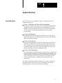
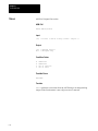
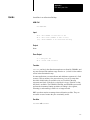
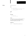
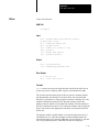
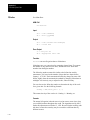
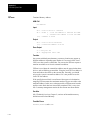
System Modularity
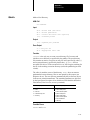
OS-9 has four levels of modularity. These are described below and
illustrated in Figure 1.1.
Level 1 – The Kernel, the Clock, and the Init Modules
The Kernel provides basic system services including Input/Output (I/O)
management, process control, and resource management. The Clock
module is a software handler for the specific real-time-clock hardware.
The Init module is an initialization table the kernel uses during
system startup.
Level 2 – File Managers
File Managers process I/O requests for similar classes of I/O devices.
Refer to the I/O Overview in this chapter for a list of the File Managers
Microware currently supports.
Level 3 – Device Drivers
Device Drivers handle the basic physical I/O functions for specific I/O
controllers. Standard OS-9 systems are typically supplied with a disk
driver, serial port drivers for terminals and serial printers, and a driver
for parallel printers. You can also add customized drivers of your own
design or purchase drivers from a hardware vendor.
Level 4 – Device Descriptors
Device Descriptors are small tables that associate specific I/O ports with
their logical name, device driver, and file manager. These modules also
contain the physical address of the port and initialization data. By using
device descriptors, only one copy of each driver is required for each
specific type of I/O device, regardless of how many devices the
system uses.
For specific information about file managers, device drivers, and device
descriptors, refer to the I/O Overview (in this chapter), the OS-9 I/O
System (Chapter 3), and the OS-9 Technical I/O Manual.
1-1
Chapter 1
System Overview
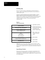
Figure 1.1
OS-9 Module Organization
User Applications
and Utilities
Math Trap Handlers
Init
OS–9 KERNEL
Clock
CIO Library
User Trap Handlers
File Managers
Device Drivers
Device Descriptors
Important: The shaded boxes contain non-executable code. These
modules are referenced, not “called.” The kernel, file managers, and
drivers reference descriptors directly, but only the kernel references the Init
module directly.
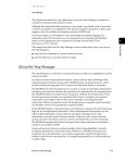
An important component, the command interpreter (the Shell), is not
shown in the above diagram. The Shell is an application program, not part
of the operating system. It is described fully in Using Professional OS-9.
To obtain a list of the specific modules that make up OS-9 for your system,
use the Ident utility on the OS9Boot file.
Although all modules could be resident in ROM, the system bootstrap
module is usually the only ROMed module in disk-based systems. All
other modules are loaded into RAM during system startup.
1-2
Chapter 1
System Overview
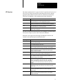
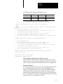
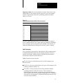
I/O Overview
The kernel maintains the I/O system for OS-9. It provides the first level of
I/O service by routing system call requests between processes, and the
appropriate file managers and device drivers. Microware includes the
following File Managers in the standard professional distribution:
File Manager:
Description:
RBF
The Random Block File Manager handles I/O for random-access,
block-structured devices, such as floppy/hard disk systems.
SCF
The Sequential Character File Manager handles I/O for sequentially
character-structured devices, such as terminals, printers, and modems.
SBF
The Sequential Block File Manager handles I/O for sequentially
block-structured devices, such as tape systems.
PIPEMAN
The Pipe File Manager supports interprocess communications through
memory buffers called pipes.
For specific information about the above file managers, refer to the OS-9
I/O System (Chapter 4) or the OS-9 Technical I/O Manual.
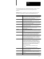
Microware also supports the following File Managers which are not
included in the standard professional distribution:
File Manager:
Description:
PCF
PC File Manager handles reading/writing PC-DOS disks. It uses RBF
drivers and is sold separately.
NFM
Network File Manager processes data requests over the OS-9 network.
The OS-9/NFM package includes NFM.
ENPMAN
ENP10 Socket File Manager transfers requests to and from CMC ENP10
boards. OS-9/ESP, the Ethernet Support Package, includes NPMAN.
SOCKMAN
Socket File Manager creates and manages the interface to
communication protocols (sockets). OS-9/ISP, the Internet Support
Package, includes SOCKMAN.
IFMAN
Communications Interface File Manager manages network interfaces.
OS-9/ISP, the Internet Support Package, includes IFMAN.
PKMAN
Pseudo-Keyboard File Manager provides an interface to the driver side of
SCF to enable the software to emulate a terminal. OS-9/ESP and
OS-9/ISP Packages include PKMAN.
GFM
The Graphics File Manager provides a full set of text and graphics
primitives, input handling for keyboards and pointers, and high level
features for handling user interaction in a real time, multi-tasking
environment. The OS-9 RAVE package includes the Graphics File
Manager.
UCM
The User Communications Manager handles video, pointer, and keyboard
devices for CDI (Compact Disc Interactive). The CD-RTOS package
includes UCM.
CDFM
The Compact Disc File Manager handles CD and audio devices, as well
as access to CD ROM and CD audio. The CD-RTOS package
includes CDFM.
NRF
The Non-Volatile RAM File Manager controls non-volatile RAM and
handles a flat (non-hierarchical) directory structure. The CD-RTOS
package includes NRF.
1-3
Chapter 1
System Overview
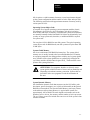
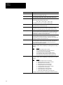
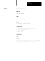
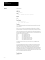
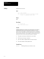
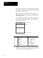
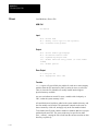
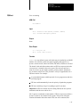
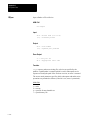
Figure 1.2 illustrates how OS-9 processes an I/O request:
Figure 1.2
Processing an OS-9 I/O Request
User Process
The user makes a request for data/status.
The Kernel identifies and validates the
I/O request and the identifies the
appropriate File Manager, Device
Driver, and other necessary
resources. Then, the Kernel passes
the request to the appropriate File
Manager.
OS–9 KERNEL
The File Manager validates the request and
performs device-independent processing.
The File Manager calls the Device Driver
for hardware interaction, as needed.
File Manager
The user receives the data/status.
The Kernel works with the File Manager
to return the data/status to the user.
The File Manager monitors and processes
the data/status and makes requests to the
Kernel for dynamic memory allocation, as
needed.
Device Driver
The Device Driver performs device-specific
processing and usually transfers the data/
status back to the File Manager.
Memory Modules
OS-9 is unique in that it uses memory modules to manage both the
physical assignment of memory to programs and the logical contents of
memory. A memory module is a logical, self-contained program, program
segment, or collection of data.
OS-9 supports ten pre-defined types of modules and allows you to define
your own module types. Each type of module has a different function.
Modules do not have to be complete programs or written in machine
language. However, they must be re-entrant, position-independent, and
conform to the basic module structure described in the next section.
1-4
Chapter 1
System Overview
The 68000 instruction set supports a programming style called re-entrant
code, that is, code that does not modify itself. This allows two or more
different processes to share one “copy” of a module simultaneously. The
processes do not affect each other, provided that each process has an
independent area for its variables.
Almost all OS-9 family software is re-entrant, and therefore uses memory
very efficiently. For example, Scred requires 26K bytes of memory to load.
If you make a request to run Scred while another user (process) is running
it, OS-9 allows both processes to share the same copy, thus saving 26K
of memory.
Important: Data modules are an exception to the re-entrant requirement.
However, careful coordination is required for several processes to update a
shared data module simultaneously.
It does not matter where a position-independent module is loaded in
memory. This allows OS-9 to load the program wherever memory space is
available. In many operating systems, you must specify a load address to
place the program in memory. OS-9 determines an appropriate load
address for you when the program is run.
OS-9 compilers and interpreters automatically generate
position-independent code. In assembly language programming, however,
the programmer must insure position-independence by avoiding absolute
address modes. Alternatives to absolute addressing are described in the
OS-9/68000 Assembler/Linker/Debugger User’s Manual.
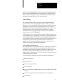
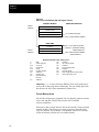
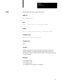
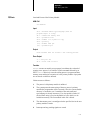
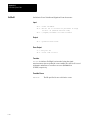
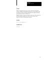
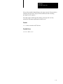
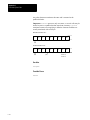
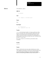
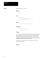
Basic Module Structure
Each module has three parts: a module header, a module body, and a
CRC value (see Figure 1.3).
Figure 1.3
Basic Memory Module Format
MODULE HEADER
MODULE BODY
Initialization data
Program/Constants
CRC VALUE
The module header contains information that describes the module and its
use. It is defined in assembly language by a psect directive. The linker
creates the header at link-time. The information contained in the module
header includes the module’s name, size, type, language, memory
requirements, and entry point. For specific information about the structure
and individual fields of the module header, refer to the list at the end of
this chapter.
1-5
Chapter 1
System Overview
The module body contains initialization data, program instructions,
constant tables, etc.
The last three bytes of the module hold a CRC value (Cyclic Redundancy
Check value) to verify the module’s integrity. The linker creates the CRC
at link-time.
The CRC Value
The CRC (Cyclic Redundancy Check) is an error checking method used
frequently in data communications and storage systems. It is also a vital
part of the ROM memory module search technique. A CRC value is at the
end of all modules to check the validity of the entire module. It provides an
extremely reliable assurance that programs in memory are intact before
execution, and is an effective backup for the error detection systems of
disk drives, memory systems, etc.
OS-9 computes a 24-bit CRC value over the entire module, starting at the
first byte of the module header and ending at the byte just before the CRC
itself. OS-9 family compilers and linkers automatically generate the
module header and CRC values. If required, your program can use the
F$CRC system call to compute a CRC value over any specified databytes.
Refer to F$CRC in the OS-9 System Calls manual for a full description of
how F$CRC computes a module’s CRC.
OS-9 does not recognize a module with an incorrect CRC value. Therefore,
you must update the CRC value of any “patched” or modified module, or
OS-9 cannot load the module from disk or find it in ROM. Use the OS-9
Fixmod utility to update the CRC’s of patched modules.
ROMed Memory Modules
When a system reset starts OS-9, the kernel searches for modules in ROM.
It detects them by looking for the module header sync code ($4AFC).
When the kernel detects this byte pattern, it checks the header parity to
verify a correct header. If this test succeeds, the kernel obtains the module
size from the header and computes a 24-bit CRC over the entire module. If
the computed CRC is valid, the module is entered into the module
directory.
OS-9 links to all of its component modules found during the search. It
automatically includes in the system module directory all ROMed modules
present in the system at startup. This allows you to create systems that are
partially or completely ROM-based. It also includes any non-system
modules found in ROM. This allows location of user-supplied software
during the start-up process, and its entry into the module directory.
1-6
Chapter 1
System Overview
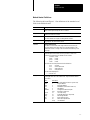
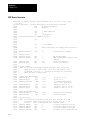
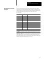
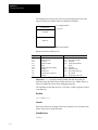
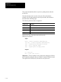
Module Header Definitions
The following table and Figure 1.1 list definitions of the standard set of
fields in the module header.
Name:
Description:
M$ID
Sync bytes ($4AFC)
These constant bytes identify the start of a module.
M$SysRev
System revision identification
Identifies the format of a module.
M$Size
Size of module
The overall module size in bytes, including header and CRC.
M$Owner
Owner ID
The group/user ID of the module’s owner.
M$Name
Offset to module name
The address of the module name string relative to the start (first sync
byte) of the module. The name string can be located anywhere in the
module and consists of a string of ASCII characters terminated by a null
(zero) byte.
M$Accs
Access permissions
Defines the permissible module access by its owner or other users.
Module access permissions are divided into four sections:
reserved (4 bits)
public
(4 bits)
group
(4 bits)
owner
(4 bits)
Each of the non-reserved permission fields is defined as:
bit 3
reserved
bit 2
execute permission
bit 1
write permission
bit 0
read permission
The total field is displayed as:
-–––––ewr–ewr–ewr
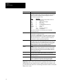
M$Type
Module Type Code
Module type values are in the oskdefs.d file. They describe the module
type code as:
Name:
Prgm
Sbrtn
Multi
Data
CSDData
TrapLib
Systm
Flmgr
Drivr
Devic
Description:
0
Not Used (Wild Card value in system calls)
1
Program Module
2
Subroutine Module
3
Multi-Module (reserved for future use)
4
Data Module
5
Configuration Status Descriptor
6-10
Reserved for future use
11
User Trap Library
12
System Module (OS-9 component)
13
File Manager Module
14
Physical Device Driver
15
Device Descriptor Module
16-up
User Definable
1-7
Chapter 1
System Overview
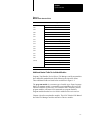
Name:
Description:
M$Lang
Language
You can find module language codes in the oskdefs.d file. They describe
whether the module is executable and which language the run-time
system requires for execution (if any):
Name:
Objct
ICode
PCode
CCode
CblCode
FrtnCode
I-code
Description:
0
Unspecified Language (Wild Card value in
system calls)
1
68000 machine language
2
Basic I-code
3
Pascal P-code
4
C I-code (reserved for future use)
5
Cobol I-code
6
Fortran
7-15
Reserved for future use
16-255 User Definable
NOTE: Not all combinations of module type codes and languages
necessarily make sense.
M$Attr
Attributes
Bit 5 - Module is a “system state” module.
Bit 6 - Module is a sticky module. A sticky module is retained in memory
when its link count becomes zero. The module is removed from memory
when its link count becomes –1 or memory is required for another use.
Bit 7 - Module is re-entrant (sharable by multiple tasks).
M$Revs
Revision level
The module’s revision level. If two modules with the same name and type
are found in the memory search or loaded into memory, only the module
with the highest revision level is kept. This enables easy substitution of
modules for update or correction, especially ROMed modules.
M$Edit
Edition
The software release level for maintenance. OS-9 does not use this field.
Every time a program is revised (even for a small change), increase this
number. We recommend that you key internal documentation within the
source program to this system.
M$Usage
Comments
Reserved for offset to module usage comments (not currently used).
M$Symbol
Symbol table offset
Reserved for future use.
M$Parity
Header parity check
The one’s complement of the exclusive-OR of the previous header
“words.” OS9 uses this for a quick check of the module’s integrity.
Important: Offset refers to the location of a module field, relative to the
starting address of the module. Resolve module offsets in assembly code
by using the names shown here and linking the module with the relocatable
library, sys.l or usr.l.
1-8
Chapter 1
System Overview
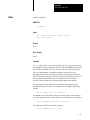
Figure 1.1
Module Header Standard Fields
Offset:
Name:
Usage:
$00
M$ID
Sync Bytes ($4AFC)
$02
M$SysRev
Revision ID
$04
M$Size
Module Size
$08
M$Owner
Owner ID
$0C
M$Name
Module Name Offset*
$10
M$Accs
Access Permissions
$12
M$Type
Module Type
$13
M$Lang
Module Language
$14
M$Attr
Attributes
$15
M$Revs
Revision Level
$16
M$Edit
Edit Edition
$18
M$Usage
Usage Comments Offset*
$1C
M$Symbol
Symbol Table
$20
$2E
Reserved
M$Parity
$30-up
Header Parity Check
Module Type Dependent
Module Body
CRC Check
* These fields are offset to strings.
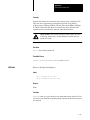
Additional Header Fields For Individual Modules
Program, Trap Handler, Device Driver, File Manager, and System modules
have additional standard header fields following the universal offsets.
These additional fields are listed below and shown in Figure 1.2.
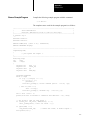
The program module is a common type of module (type: Prgm; language:
Objct). A program module is executable as an independent process by the
F$Fork or F$Chain system calls. The assembler and C compilers produce
program modules, and most OS-9 commands are program modules.
Program module headers have six fields in addition to the universal set.
Chapter 4 describes trap handler modules. The OS-9 Technical I/O Manual
describes File Manager modules and Device Drivers modules.
1-9
Chapter 1
System Overview
Name:
Description:
(Program, Trap Handler, Device Driver, File Manager, and System Module Headers use the following two fields.)
M$Exec
Execution offset
The offset to the program’s starting address. In the case of a file manager or driver, this is
the offset to the module’s entry table.
M$Excpt
Default user trap execution entry point
The relative address of a routine to execute if an uninitialized user trap is called.
(Program, Trap Handler, and Device Driver Module Headers use the following field.)
M$Mem
Memory size
The required size of the program’s data area (storage for program variables).
(Program and Trap Handler Module Headers use the following three fields.)
M$Stack
Stack size
The minimum required size of the program’s stack area.
M$IData
Initialized data offset
The offset to the initialization data area’s starting address. This area contains values to
copy to the program’s data area. The linker places all constant values declared in vsects
here. The first four-byte value is the offset from the beginning of the data area to which the
initialized data is copied. The next four-byte value is the number of initialized data-bytes to
follow.
M$IRefs
Initialized references offset
The offset to a table of values to locate pointers in the data area. Initialized variables in the
program’s data area may contain values that are pointers to absolute addresses. Adjust
code pointers by adding the absolute starting address of the object code area. Adjust the
data pointers by adding the absolute starting address of the data area.
The F$Fork system call does the effective address calculation at execution time using
tables created in the module. The first word of each table is the most significant (MS) word
of the offset to the pointer. The second word is a count of the number of least significant
(LS) word offsets to adjust. F$Fork makes the adjustment by combining the MS word with
each LS word entry. This offset locates the pointer in the data area. The pointer is adjusted
by adding the absolute starting address of the object code or the data area (for code
pointers or data pointers respectively). It is possible after exhausting this first count that
another MS word and LS word are given. This continues until a MS word of zero and a LS
word of zero are found.
(Trap Handler Module Headers use the following two fields.)
M$Init
Initialization execution offset
The offset to the trap initialization entry point.
M$Term
Termination execution offset
The offset to the trap termination entry point. This offset is reserved by Microware for future
use.
Important: Offset refers to the location of a module field, relative to the
starting address of the module. Resolve module offsets in assembly code
by using the names shown here and linking the module with the relocatable
library: sys.l or usr.l.
1-10
Chapter 1
System Overview
Figure 1.2
Additional Header Fields for Individual Modules
Module type:
Offset:
Usage:
File Manager/System
$30
Execution Offset
$34
Default User Trap Execution
Entry Point
$38
Memory Size
$3C
Stack Size
Device Driver
$40
Initialized Data Offset
Program
$44
Initialized Reference Offset
Trap Handlers
$48
Initialization Execution Offset
$4C
Termination Execution Offset
1-11
Chapter
2
The Kernel
Responsibilities of the
Kernel
The kernel is the nucleus of OS-9. It manages resources, controls
processing, and supervises Input/Output. It is a ROMable, compact
OS-9 module.
The kernel’s primary responsibility is to process and coordinate system
calls, or service requests. OS-9 has two general types of system calls:
calls that perform Input/Output, such as reads and writes
calls that perform system functions. System functions include memory
management, system initialization, process creation and scheduling, and
exception/interrupt processing
When a system call is made, a user trap to the kernel occurs. The kernel
determines what type of system call the user wants to perform. It directly
executes the calls that perform system functions, but does not execute I/O
calls. The kernel provides the first level of processing for each I/O call,
then completes the function as required by calling the appropriate file
manager or driver.
For information on specific system calls, refer to the OS-9 System Calls
section of this manual.
For specific information about creating new file managers, and examples
which you can adapt to your specific system needs, refer to the OS-9
Technical I/O Manual.
System Call Overview
For information about specific system calls, refer to OS-9 System Calls.
2-1
Chapter 2
The Kernel
User-state and System-state
To understand OS-9’s system calls, you should be familiar with the two
distinct OS-9 environments in which object code can be executed:
Environment:
Description:
User-state
The normal program environment in which processes execute.
Generally, user-state processes do not deal directly with the specific
hardware configuration of the system.
System-state
The environment in which OS-9 system calls and interrupt service
routines execute. On 68000-family processors, this is synonymous
with supervisor state. System-state routines often deal with physical
hardware present on a system.
Functions executing in system state have distinct advantages over those
running in user state, including the following:
A system-state routine has access to all of the processor’s capabilities.
For example, on memory protected systems, a system-state routine may
access any memory location in the system. It may mask interrupts, alter
OS-9 internal data structures, or take direct control of hardware
interrupt vectors.
Some OS-9 system calls are only accessible from system state.
System-state routines are never time-sliced. Once a process enters
system state, no other process executes until the system-state process
finishes or goes to sleep (F$Sleep waiting for I/O). The only processing
that may preempt a system-state routine is interrupt servicing.
System-state characteristics make it the only way to provide certain types
of programming functions. For example, it is almost impossible to provide
direct I/O to a physical device from user state. Not all programs, however,
should run in system state. Reasons to use user-state processing rather than
system-state processing include:
User-state routines are time-sliced. In a multi-user environment, it is
important to ensure that each user receives a fair share of the CPU time.
Memory protection prevents user-state routines from accidentally
damaging data structures they do not own.
A user-state process can be aborted. If a system-state routine loses
control, the entire system usually crashes.
System-state routines are far more difficult and dangerous to debug than
userstate routines. You can use the user-state debugger to find most
user-state problems. Generally, system-state problems are much more
difficult to find.
User-state programs are essentially isolated from physical hardware.
Because they are not concerned with I/O details, they are easier to write
and port.
2-2
Chapter 2
The Kernel
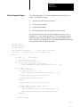
Installing System-state Routines
System-state routines have direct access to all system hardware, and have
the power to take over the entire machine, crashing or hanging up the
system. To help prevent this, OS9 limits the methods of creating routines
that operate in system state.
There are four ways to provide system-state routines:
Install an OS9P2 module in the system bootstrap file or in ROM. During
cold start, the OS-9 kernel links to this module, and if found, calls its
execution entry point. The most likely thing for such a module to do is
install new system call codes. The drawback to this method is that the
OS9P2 module must be in ROM or in the bootfile when the system
is bootstrapped.
Use the I/O system as an entry into system state. File managers and
device drivers always execute in system state. The most obvious reason
to write systemstate routines is to provide support for new hardware
devices. It is possible to write a dummy device driver and use the
I$GetStt or I$SetStt routines to provide a gateway to the driver.
Write a trap handler module that executes in system state. For routines
of limited use that are dynamically loaded and unlinked, this may be the
most convenient method. In many cases, it is practical to debug most of
the trap handler routines in user state, then convert the trap module to
system state. To make a trap handler execute in system state, you must
set the supervisor state bit in the module attribute byte and create the
module as super user. When the user trap executes, it is in system state.
A program executes in system state if the supervisor state bit in the
module’s attribute word is set and the module is owned by the super
user. This can be useful in rare instances.
Important: System-state routines are not time-sliced, therefore they
should be as short and fast as possible.
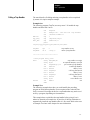
Kernel System Call Processing
All OS-9 system calls (service requests) are processed through the kernel.
The system-wide relocatable library files, sys.l and usr.l, define symbolic
names for all system calls. The files are linked with hand-written assembly
language or compiler-generated code. The OS-9 Assembler has a built-in
macro to generate system calls:
OS9
I$Read
2-3
Chapter 2
The Kernel
This is recognized and assembled to produce the same code as:
TRAP
dc.w
#0
I$Read
In addition, the C Compiler standard library includes functions to access
nearly all user mode OS-9 system calls from C programs.
Parameters for system calls are usually passed and returned in registers.
There are two general types of system calls: system function calls (calls
that do not perform I/O) and I/O calls.
System Function Calls
There are two types of system function calls, user-state and system-state:
Type:
Description:
User-state System Calls
These requests perform memory management, multi-tasking, and
other functions for user programs. They are mainly processed by
the kernel.
System-state System Calls
Only system software in system state can use these calls, and
they usually operate on internal OS-9 data structures. To
preserve OS-9’s modularity, these requests are system calls
rather than subroutines. User-state programs cannot access
them, but system modules such as device drivers may use them.
The symbolic name of each system function call begins with F$. For
example, the system call to link a module is F$Link.
In general, system-state routines may use any of the user-state system calls.
However, you must avoid making system calls at inappropriate times. For
example, avoid I/O calls, timed sleep requests, and other calls that can be
particularly time consuming (such as F$CRC) in an interrupt
service routine.
Memory requested in system state is not recorded in the process descriptor
memory list. Therefore, you must ensure that the memory is returned to the
system before the process terminates.
ATTENTION: Avoid the F$TLink and F$Icpt system calls in
system-state routines. Certain portions of the C library may be
inappropriate for use in system state.
2-4
Chapter 2
The Kernel
I/O Calls
I/O calls perform various I/O functions. The file manager, device driver,
and kernel process I/O calls for a particular device. The symbolic names
for this category of calls begin with I$. For example, the read service
request is I$Read.
You may use any I/O system call in a system-state routine, with one slight
difference than when executed in user-state. All path numbers used in
system state are system path numbers. Each process descriptor has a path
number that converts process local path numbers into system path
numbers. The system itself has a global path number table to convert
system path numbers into actual addresses of path descriptors. You must
make system-state I/O system calls using system path numbers.
For example, the OS-9 F$PErr system call prints an error message on the
caller’s standard error path. To do this, it may not simply perform output
on path number two. Instead it must examine the caller’s process descriptor
and extract the system path number from the third entry (0, 1, 2, ...) in the
caller’s path table.
When a user-state process exits with I/O paths open, the F$Exit routine
automatically closes the paths. This is possible because OS-9 keeps track
of the open paths in the process’s path table. In system state, the I$Open
and I$Create system calls return a system path number which is not
recorded in the process path table or anywhere else by OS-9. Therefore,
the system-state routine that opens any I/O paths must ensure that the paths
are eventually closed, even if the underlying process is abnormally
terminated.
Memory Management
To load any object (such as a program or constant table) into memory, the
object must have the standard OS-9 memory module format as described in
Chapter 1. This enables OS-9 to maintain a module directory to keep
track of modules in memory. The module directory contains the name,
address, and other related information about each module in memory.
OS-9 adds the module to the module directory when it is loaded into
memory. Each directory entry contains a link count. The link count is the
number of processes using the module.
When a process links to a module in memory, the module’s link count
increments by one. When a process unlinks from a module, the module’s
link count decrements by one. When a module’s link count becomes zero,
its memory is de-allocated and it is removed from the module directory,
unless the module is sticky.
A sticky module is not removed from memory until its link count becomes
–1 or memory is required for another use. A module is sticky if the sixth
bit of the module header’s attribute field (M$Attr) is set.
2-5
Chapter 2
The Kernel
OS-9 Memory Map
OS-9 uses a software memory management system that contains all
memory within a single memory map. Therefore, all user tasks share a
common address space.
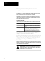
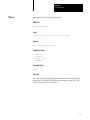
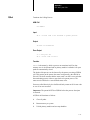
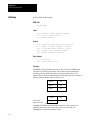
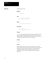
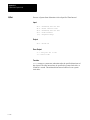
A map of a typical OS-9 memory space is shown in Figure 2.1. Unless
otherwise noted, the sections shown need not be located at specific
addresses. However, Microware recommends that you keep each section in
contiguous reserved blocks, arranged in an order that facilitates future
expansion. Whenever possible, it is best to have physically
contiguous RAM.
Figure 2.1
Typical OS-9 Memory Map
Highest Memory Address
I/O Device Addresses
Bootstrap ROM located here
Bootstrap ROM and/or Optional ROM’s
For System or Application Software
Unused: Available For Future
with first 8 bytes (reset vector)
also mapped to vector
locations: 000000–000007.
RAM or ROM Expansion
RAM in multiples of 8K
RAM
128K minimum
contiguous, expanded
upward
512K recommended
(the more the better)
Address 000400
ROM or RAM For Exception Vectors
Address 000008
ROM Reset Vectors
Address 000000
Important: For the 68020, 68030, 68040, and CPU32 family of CPUs,
you can set the Vector Base Register (VBR) anywhere in the system. Thus,
for these types of systems, there is no requirement that RAM or ROM be at
address 0.
System Memory Allocation
During the OS-9 start-up sequence, an automatic search function in the
kernel and the boot ROM finds blocks of RAM and ROM. OS-9 reserves
some RAM for its own data structures. ROM blocks are searched for valid
OS-9 ROM modules.
2-6
Chapter 2
The Kernel
OS-9 requires a variable amount of memory. Actual requirements depend
on the system configuration and the number of active tasks and open files.
The following sections describe approximate amounts of memory used by
various parts of OS-9.
Operating System Object Code
A complete set of typical operating system component modules (kernel,
file managers, device drivers, device descriptors, tick driver) occupies
about 50K to 64K bytes of memory. On disk-based systems, these modules
are normally bootstrap-loaded into RAM. OS-9 does not dynamically load
overlays or swap system code; therefore, no additional RAM is required
for system code.
You can place OS-9 in ROM for non-disk systems. The typical operating
system object code for ROM-based, non-disk systems occupies about 30K
to 40K bytes.
System Global Memory
OS-9 uses a minimum of 8K RAM for internal use. The system global
memory area is usually located at the lowest RAM addressed. It contains
an exception jump table, the debugger/boot variables, and a system global
area. Variables in the system global area are symbolically defined in the
sys.l library and the variable names begin with D_. The Reset SSP vector
points to the system global area.
ATTENTION: User programs should never directly access
system global variables because of issues such as portability and
(depending on hardware) memory protection. System calls are
provided to allow user programs to read the information in
this area.
System Dynamic Memory
OS-9 maintains dynamic-sized data structures (such as I/O buffers, path
descriptors, process descriptors, etc.) which are allocated from the general
RAM area when needed. The System Global Memory area keeps pointers
to the addresses of these data structures. A typical small system uses
approximately 16K of RAM. The total depends on elements such as the
number of active devices, the memory, and the number of active processes.
The sys.l library source files include the exact sizes of all the system’s data
structure elements.
2-7
Chapter 2
The Kernel
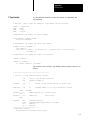
Free Memory Pool
All unused RAM memory is assigned to a free memory pool. Memory
space is removed and returned to the pool as it is allocated or de-allocated
for various purposes. OS-9 automatically assigns memory from the free
memory pool whenever any of the following occur:
Modules are loaded into RAM.
New processes are created.
Processes request additional RAM.
OS-9 requires more I/O buffers or its internal data structures must
be expanded.
Storage for user program object code modules and data space is
dynamically allocated from and de-allocated to the free memory pool. User
object code modules are automatically shared if two or more tasks execute
the same object program. User object code application programs can also
be stored in ROM memory.
The total memory required for user memory depends largely on the
application software to be run. Microware suggests that you have a system
minimum of 128K plus an additional 64K per user available. Alternatively,
small ROM-based control system might only need 32K of memory.
Memory Fragmentation
Once a program is loaded, it must remain at the address where it was
originally loaded. Although position-independent programs can be initially
placed at any address where free memory is available, program modules
cannot be relocated dynamically after they are loaded. This can lead to
memory fragmentation.
When programs are loaded, they are assigned the first sufficiently large
block of memory at the highest address possible in the address space. (If a
colored memory request is made, this may not be true. Refer to the
following section for more information on colored memory.) If a number
of program modules are loaded, and subsequently one or more
non-contiguous modules are unlinked, several fragments of free memory
space exist. The total free memory space may be quite large. However,
because it is scattered, not enough space will exist in a single block to load
a particular program module.
You can avoid memory fragmentation by loading modules at system
startup. This places the modules in contiguous memory space. Or, you can
initialize each standard device when booting the system. This allows the
devices to allocate memory from higher RAM than would be available if
the devices were initialized after booting.
2-8
Chapter 2
The Kernel
If serious memory fragmentation does occur, the system administrator can
kill processes and unlink modules in ascending order of importance until
there is sufficient contiguous memory to proceed. Use the mfree utility to
determine the number and size of free memory blocks.
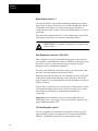
Colored Memory
OS-9 colored memory allows a system to recognize different memory
types and reserve areas for special purposes. For example, you could
design a part of a system’s RAM to store video images and battery back up
another part. The kernel allows isolation and specific access of areas of
RAM like these. You can request specific memory types or “colors” when
allocating memory buffers, creating modules in memory, or loading
modules into memory. If a specific type of memory is not available, the
kernel returns error #237, E$NoRAM.
Colored memory lists are not essential on systems with RAM consisting of
one homogeneous type, although they can improve system performance on
some systems and allow greater flexibility in configuring memory search
areas. The default memory allocation requests are still appropriate for most
homogeneous systems and for applications which do not require one
memory type over another. Colored memory lists are required for the
F$Trans system call to perform address translation.
Colored Memory Definition List
The kernel must have a description of the CPU’s address space to make use
of the colored memory routines. You can establish colored memory by
including a colored memory definition list (MemList) in the systype.d file,
which then becomes part of the Init module. The list describes each
memory region’s characteristics. The kernel searches each region in the list
for RAM during system startup.
A colored memory definition list contains the following information:
memory color (type)
memory priority
memory access permissions
local bus address
block size the kernel’s coldstart routine uses to search the area for RAM
or ROM
external bus translation address (for DMA, dual-ported RAM, etc.)
optional name
2-9
Chapter 2
The Kernel
The memory list may contain as many regions as needed. If no list is
specified, the kernel automatically creates one region that describes the
memory found by the bootstrap ROM.
MemList is a series of MemType macros defined in systype.d and used by
init.a. Each line in the MemList must contain all the following parameters,
in order:
type, priority, attributes, blksiz, addr begin, addr end, name, DMA-offset
The colored memory list must end with a longword of zero. The following
describes the MemList parameters:
Parameter:
Size:
Size:
Memory Type
word
Type of memory. Three memory types are currently defined in
memory.h:
SYSRAM
VIDEO1
VIDEO2
0x01
0x80
0x81
System RAM memory
Video memory for plane A
Video memory for plane B
Priority
word
Priority of memory (0-255). High priority memory is allocated
first. If the block priority is 0, then the block can only be
allocated by a request for the specific color (type) of the block.
Access permissions
word
Memory type access bit definitions:
bit 0
B_USER
User processes can allocate this memory.
NOTE: This bit is ignored if the B_ROM bit
is set.
bit 1
B_PARITY Parity memory; the kernel initializes this
memory during startup.
NOTE: Only B_USER memory may be
initialized.
bit 2
B_ROM
ROM; the kernel searches this memory for
modules during startup.
NOTE: B_ROM memory cannot be
allocated by processes, as the B_USER
and B_PARITY bits are ignored if B_ROM
is set.
2-10
Search Block Size
word
The kernel checks every search block size to see if
RAM/ROM exists.
Low Memory Limit
long
Beginning address of the block, as referenced by the CPU.
High Memory Limit
long
End address of the block, as referenced by the CPU.
Description String Offset
word
Offset of a user-defined string that describes the type of
memory block.
Address Translation
Adjustment
long
The external bus address of the beginning of the block. If zero,
this field does not apply. Refer to F$Trans for more information.
Chapter 2
The Kernel
The following is an example system memory map:
CPU address:
Bus address:
Memory size:
Physical location:
$00000000
$00200000
$200000
on-board cpu ram
$00600000
$00600000
$200000
VMEbus ram
A corresponding MemList table might appear as follows:
* memory list definitions for init module (user adjustable)
align
* MemType type, prior, attributes, blksiz, addr limits, name, DMA–offset
MemList
* on–board ram covered by “rom memory list:”
* – this memory block is known to the “rom’s memory list,” thus it was
*
“parity initialized” by the rom code.
* – the cpu’s local base address of the block is at $00000000.
* – the bus base address of the block is at $200000.
* – this ram is fastest access for the cpu, so it has the highest priority.
*
MemType SYSRAM,255,B_USER,4096,0,$200000,OnBoard,$200000
* off–board expansion ram
* – this memory block is not known to the “rom’s memory list,”
*
thus it needs “parity initialization” by the kernel.
* – as the block is accessed over the bus, the base address of the block
*
is the same for cpu and dma accesses.
* – this ram is slower access than on–board ram, therefore it
*
has a lower priority than the on–board ram.
*
MemType SYSRAM,250,B_USER+B_PARITY,4096,$600000,$800000,OffBoard,0
dc.l 0 end of list
OnBoard dc.b “fast on–board RAM”,0
OffBoard dc.b “VMEbus memory”,0
Colored Memory in Homogenous Memory Systems
Colored memory definitions are not essential for homogenous memory
systems. However, colored memory definitions in this type of system can
improve system performance and simplify memory list re-configuration.
System Performance
In a homogeneous memory system, the kernel allocates memory from the
top of available RAM when requests are made by F$SRqMem (for
example, when loading modules). If the system has RAM on-board the
CPU and off-board in external memory boards, the modules tend to be
loaded into the off-board RAM, because OS-9 always uses high memory
first. On-board RAM is not used for a F$SRqMem call until the off-board
memory is unable to accommodate the request.
2-11
Chapter 2
The Kernel
Programs running in off-board memory execute slower than those running
in on-board memory, due to bus access arbitration. Also, external bus
activity increases. This may impact the performance of other bus masters
in the system.
The colored memory lists can be used to reverse this tendency in the
kernel, so that a CPU does not use off-board memory until all of its
on-board memory is utilized. This results in faster program execution and
less saturation of the system’s external bus. Do this by making the priority
of the on-board memory higher than off-board memory, as shown in the
example lists on the preceding page.
Re-configuring Memory Areas
In a homogeneous memory system, the memory search areas are defined in
the ROM’s Memory List. If you do not use colored memory, you must
make new ROMs from source code (usually impossible for end-users) or
from a patched version of the original ROMs (usually difficult for
end-users) to make changes to the memory search areas.
The colored memory lists simplify changes by configuring the search areas
as follows:
The ROM’s memory list describes only the on-board memory.
The colored memory lists in systype.d define the on-board memory and
any external bus memory search areas in the Init module only.
The use of colored memory in a homogeneous memory system allows you
to easily reconfigure the external bus search areas by adjusting the lists in
systype.d and making a new Init module. The ROM does not
require patching.
System Initialization
After a hardware reset, the bootstrap ROM executes the kernel (which is
located in ROM or loaded from disk, depending on the system involved).
The kernel initializes the system, which includes locating ROM modules
and running the system startup task (usually Sysgo).
Init: The Configuration Module
Init is a non-executable module of type Systm (code $0C) which contains
a table of system startup parameters. During startup, Init specifies initial
table sizes and system device names, but it is always available to determine
system limits. It must be in memory when the kernel executes and usually
resides in the OS9Boot file or in ROM.
2-12
Chapter 2
The Kernel
The Init module begins with a standard module header (Chapter 1, Figure
1-4) and the additional fields shown in the following table and in
Table 2.A.
Important: Refer to Appendix A for an example program listing of the
Init module. Offset names are defined in the relocatable library sys.l.
Name:
M$PollSz
M$DevCnt
Description:
IRQ polling size
The number of entries in the IRQ polling table. Each interrupt generating
device control register requires one entry. The IRQ polling table has 32
entries by default. Each table entry is 18 bytes long.
Device table size
The number of entries in the system device table. Each device on the
system requires one entry in this table.
M$Procs
Initial process table size
The initial number of active processes allowed in the system. If this table
gets full, it automatically expands as needed.
M$Paths
Initial path table size
The initial number of open paths in the system. If this table gets full, it
automatically expand as needed.
M$SParam
Offset to parameter string for startup module
The offset to the parameter string (if any) to pass to the first
executable module.
M$SysGo
First executable module name offset
The offset to the name string of the first executable module, usually Sysgo
or Shell.
M$SysDev
Default directory name offset
The offset to the initial default directory name string, usually /d0 or /h0.
The kernel does a chd and chx to this device prior to forking the initial
device. If the system does not use disks, this offset must be zero.
Initial I/O pathlist name offset
The offset to the initial I/O pathlist string, usually /term. This pathlist is
opened as the standard I/O path for the initial process. It is generally used
to set up the initial I/O paths to and from a terminal. This offset should
contain zero if no console device is in use.
M$Consol
M$Extens
Customization module name offset
The offset to the name string of a list of customization modules (if any). A
customization module complements or changes the existing OS-9
standard system calls. These modules are searched for at startup; they
are usually found in the bootfile. If found, they execute in system state.
Module names in the name string are separated by spaces. The default
name string to search for is OS9P2. If there are no customization
modules, set this value to zero.
NOTE: A customization module may only alter the d0, d1, and
ccr registers.
M$Clock
NOTE: Customization modules must be system-type modules.
Clock module name offset
The offset to the clock module name string. If there is no clock module
name string, set this value to zero.
M$Slice
Time-slice
The number of clock ticks per time-slice. If M$Slice is not specified, it
defaults to 2.
M$Site
Offset to installation site code
This value is usually set to zero. OS-9 does not currently use this field.
2-13
Chapter 2
The Kernel
Name:
M$Instal
M$CPUTyp
M$OS9Lvl
Description:
Offset to installation name
The offset to the installation name string.
CPU Type
CPU type: 68000, 68008, 68010, 68020, 68030, 68040, 68070, 683xx.
Level, version, and edition
This four byte field is divided into three parts:
level: 1 byte version: 2 bytes edition: 1 byte
M$OS9Rev
M$SysPri
M$MinPty
M$MaxAge
M$Events
M$Compat
M$Compat2
For example, level 2, version 2.4, edition 0 would be 2240.
Revision offset
The offset to the OS-9 level/revision string.
Priority
The system priority at which the first module (usually Sysgo or Shell)
executes. This is generally the base priority at which all processes start.
Minimum priority
The initial system minimum executable priority. For specific information on
minimum priority, see the Process Execution section later in this chapter
and F$SetSys in Chapter 1 of OS-9 System Calls.
Maximum age
The initial system maximum natural age. For specific information on
maximum age, see the Process Execution section later in this chapter and
F$SetSys in Chapter 1 of OS-9 System Calls.
Number of entries in the events table
The initial number of entries allowed in the events table. If the table gets
full, it automatically expands as needed. See the Events section of
Chapter 3 for more specific information.
Revision compatibility
This byte is used for revision compatibility. The following bits are currently
defined:
Function
Bit#
0
Set to save all registers for IRQ routines
1
Set to prevent the kernel from using stop instructions
2
Set to ignore sticky bit in module headers
3
Set to disable cache burst operation (68030 systems)
4
Set to patternize memory when allocated or de-allocated
5
Set to prevent kernel cold-start from starting system clock
Revision compatibility #2
This byte is used for revision compatibility. The following bits are currently
defined:
Bit#
0
1
2
3
7
Function
0 External instruction cache is not snoopy*
1 External instruction cache is snoopy or absent
0 External data cache is not snoopy
1 External data cache is snoopy or absent
0 On-chip instruction cache is not snoopy
1 On-chip instruction cache is snoopy or absent
0 On-chip data cache is not snoopy
1 On-chip data cache is snoopy or absent
0 Kernel disables data caches when in I/O
1 Kernel does not disable data caches when in I/O
* snoopy = cache that maintains its integrity without software intervention.
2-14
Chapter 2
The Kernel
Name:
M$MemList
Description:
Colored memory list
An offset to the memory segment list. The colored memory list contains an
entry for each type of memory in the system. It is terminated by a long
word of zero. See F$SRqCMem for further information. Each entry in the
list has the following format:
Offset
$00
$02
$04
Description
Memory Type;
SYSRAM
VIDEO1
VIDEO2
Priority
Access permissions:
B_USER
B_PARITY
B_ROM
M$IRQStk
M$ColdTrys
= System RAM
= Plane A Video
= Plane B Video
= User processes allocate memory.
= Parity memory; kernel initializes
it during startup.
= kernel searches this for modules
during startup.
$06
Search block size
$08
Low memory limit
$10
Offset to description string
$12
Reserved (must be zero)
$14
Address translation adjustment
$18
Reserved (must be zero)
$1C
Reserved (must be zero)
Kernel’s IRQ stack size
The size (in LONGWORDS) of the kernel’s IRQ stack. The value of this
field must be 0, or >= 256 and <=$ffff. If zero, the kernel uses a small
default IRQ stack (not recommended).
Retry counter
This is the retry counter if the kernel’s initial chd (to the default system
device) fails.
Important: Offset refers to the location of a module field, relative to the
starting address of the module. Module offsets are resolved in assembly
code by using the names shown here and linking the module with the
relocatable library: sys.l or usr.l.
2-15
Chapter 2
The Kernel
Table 2.A
Additional Fields for the Init Module
Offset:
Name:
Description:
$30
Reserved
Currently reserved for future use.
$34
M$PollSz
Number of IRQ polling table entries.
$36
M$DevCnt
Device table size.
$38
M$Procs
Initial process table size.
$3A
M$Paths
Initial path table size.
$3C
M$SParam
Parameter string for startup module (usually Sysgo).
$3E
M$SysGo
Offset to name string of first executable module.
$40
M$SysDev
Offset to the initial default directory name string.
$42
M$Consol
Offset to the initial I/O pathlist string.
$44
M$Extens
Offset to a name string of customization modules.
$46
M$Clock
Offset to the clock module name string.
$48
M$Slice
Number of clock ticks per time-slice.
$4A
Reserved
Currently reserved for future use.
$4C
M$Site
Offset to the installation site code.
$50
M$Instal
Offset to the installation name string.
$52
M$CPUTyp
CPU type.
$56
M$OS9Lvl
Level, version, and edition number of the operating
system.
$5A
M$OS9Rev
Offset to the OS-9 level/revision string.
$5C
M$SysPri
Initial system priority.
$5E
M$MinPty
Initial system minimum executable priority.
$60
M$MaxAge
Initial system maximum natural age.
$62
Reserved
Currently reserved for future use.
$66
M$Events
Initial number of entries allowed in the events table.
$68
M$Compat
Compatibility flag one. Byte is used for revision
compatibility.
$69
M$Compat2
Compatibility flag two. Byte is used for revision
compatibility.
$6A
M$MemList
Offset to the memory segment list.
$6C
M$IRQStk
Size of the kernel’s IRQ stack.
$6E
M$ColdTrys
Retry counter if the kernel’s initial chd fails.
Important: The strings themselves follow the 28 byte reserved section.
2-16
Chapter 2
The Kernel
Sysgo
Sysgo is the first user process started after the system startup sequence. Its
standard I/O is on the system console device.
Sysgo usually executes as follows:
1.
Changes to the CMDS execution directory on the system device.
2.
Executes the startup file (as a script) from the root of the
system device.
3.
Forks a shell on the system console.
4.
Waits for that shell to terminate and then forks it again. Therefore,
there is always a shell running on the system console, unless
Sysgo dies.
You cannot use the standard Sysgo module for disk systems on non-disk
systems, but it is easy to customize.
You may eliminate Sysgo by specifying shell as the initial startup module
and specifying a parameter string similar to:
startup; ex tsmon /term
See Appendix A for an example source listing of the Sysgo module.
Customization Modules
Customization modules are additional modules you can execute at boot
time to enhance OS-9’s capabilities. They provide a convenient way to
install a new system call code or collection of system call codes, for
example, a system security module. The kernel calls the modules at boot
time if their names are specified in the extension list of the Init module and
the kernel can locate them.
Important: Customization modules may only modify the d0, d1, and
ccr registers.
To include a customization module in the system, you can either burn the
module into ROM or complete the following steps:
1.
Assemble/link the module so that the final object code appears in the
/h0/CMDS/BOOTOBJS directory.
2-17
Chapter 2
The Kernel
2.
Create a new Init module:
Change to the DEFS directory and edit the CONFIG macro in the
systype.d file. The name of the new module must appear in the Init module
extension list. For example, if the name of the new module is mine, add the
following line immediately before the endm line:
Extens dc.b “os9p2 mine”,0
Important: os9p2 is the name of the default customization module.
Remake the Init module.
3.
Create a new bootfile:
Change to the /h0/CMDS/BOOTOBJS directory and edit the bootlist file
so that the customization module name appears in the list.
Create a new bootfile with the os9gen utility. For example:
os9gen /h0fmt –z=bootlist
4.
Process Creation
2-18
Reboot the system and make sure that the new module is operational.
All OS-9 programs run as processes or tasks. The F$Fork system call
creates new processes. The name of the primary module that the new
process is to execute initially is the most important parameter passed in the
fork system call. The following outlines the creation process:
1.
Locate or Load the Program.
OS-9 tries to find the module in memory. If it cannot find the module,
it loads a mass-storage file into memory using the requested module
name as a file name.
2.
Allocate and Initialize a Process Descriptor.
After OS-9 locates the primary module, it assigns a data structure
called a process descriptor to the new process. The process
descriptor is a table that contains information about the process: its
state, memory allocation, priority, I/O paths, etc. The process
descriptor is automatically initialized and maintained. The process
does not need to know about the descriptor’s existence or contents.
Chapter 2
The Kernel
3.
Allocate the Stack and Data Areas.
The primary module’s header contains a data and stack size. OS-9
allocates a contiguous memory area of the required size from the
free memory space. The following section discusses process
memory areas.
4.
Initialize the Process.
OS-9 sets the new process’s registers to the proper addresses in the
data area and object code module (see Figure 2.2). If the program
uses initialized variables and/or pointers, they are copied from the
object code area to the proper addresses in the data area.
If OS-9 cannot perform any of these steps, it aborts the creation of the new
process and notifies the process that originated the fork of the error. If
OS-9 completes all the steps, it adds the new process to the active process
queue for execution scheduling.
The new process is also assigned a process ID. This is a unique number
which is the process’s identifier. Other processes can communicate with it
by referring to its ID in system calls. The process also has an associated
group ID and user ID. These identify all processes and files belonging to
a particular user and group of users. The group and user ID’s are inherited
from the parent process.
Processes terminate when they execute an F$Exit system service request or
when they receive fatal signals or errors. Terminating the process closes
any open paths, de-allocates the process’s memory, and unlinks its
primary module.
2-19
Chapter 2
The Kernel
Figure 2.2
New Process’s Initial Memory Map and Register Contents
PRIMARY MODULE
HIGHEST
ADDRESS
REGISTER CONTENTS
CRC Check Value
Initialization Data
Executable Object Code
pc = module entry point
Module Header
(a3) = module starting address
DATA AREA
(a1) = top of memory pointer
Parameters
(a5)/(a7) = parameter starting
address/stack top
Stack
LOWEST
ADDRESS
Variables
(a6) = data area base address
(lowest address)
Registers passed to the new process:
sr
pc
d0.w
d1.l
d2.w
d3.w
d4.l
d5.l
d6.l
d7.l
0000
module entry point
process ID
group/user ID
priority
# of paths inherited
undefined
parameter size
total initial memory
allocation
undefined
(a0)
(a1)
(a2)
(a3)
(a4)
(a5)
(a6)
(a7)
undefined
top of memory pointer
undefined
primary module pointer
undefined
parameter pointer
static storage (data area) base pointer
stack pointer (same as a5)
Important: (a6) is always biased by $8000 to allow object programs to
access 64K of data using indexed addressing. You can usually ignore this
bias because the OS-9 linker automatically adjusts for it.
Process Memory Areas
OS-9 divides all processes (programs) into two logically separate memory
areas: code and data. This division provides OS-9’s modular
software capabilities.
Each process has a unique data area, but not necessarily a unique program
memory module. This allows two or more processes to share the same
copy of a program. This technique is an automatic function of OS-9 and
results in extremely efficient use of available memory.
2-20
Chapter 2
The Kernel
A program must be in the form of an executable memory module
(described in Chapter 1) to be run. The program is position-independent
and ROMable, and the memory it occupies is considered read-only. It may
link to and execute code in other modules.
The process’s data area is a separate memory space where all of the
program’s variables are kept. The top part of this area is used for the
program’s stack. The actual memory addresses assigned to the data area are
unknown at the time the program is written. A base address is kept in a
register (usually a6) to access the data area. You can read or write to
this area.
If a program uses variables that require initialization, OS-9 copies the
initial values from the read-only program area to the data area where the
variables actually reside. The OS-9 linker builds appropriate initialization
tables which initialize the variables.
Process States
A process is either in active, waiting, or sleeping state:
Process:
Description:
ACTIVE
The process is active and ready for execution. The scheduler gives active
processes time for execution according to their relative priority with
respect to all other active processes. It uses a method that compares the
ages of all active processes in the queue. It gives some CPU time to all
active processes, even if they have a very low relative priority.
WAITING
The process is inactive until a child process terminates or until a signal is
received. The process enters the wait state when it executes a F$Wait
system service request. It remains inactive until one of its descendant
processes terminates or until it receives a signal.
SLEEPING
The process is inactive for a specified period of time or until it receives a
signal. A process enters the sleep state when it executes an F$Sleep
service request. F$Sleep specifies a time interval for which the process is
to remain inactive. Processes often sleep to avoid wasting CPU time while
waiting for some external event, such as the completion of I/O. Zero ticks
specifies an infinite period of time. Processes waiting on an event are also
included in the sleep queue.
There is a separate queue (linked list of process descriptors) for each
process state. State changes are made by moving a process descriptor from
its current queue to another queue.
2-21
Chapter 2
The Kernel
Process Scheduling
OS-9 is a multi-tasking operating system, that is, two or more independent
programs, called processes or tasks, can execute simultaneously. Several
processes share each second of CPU time. Although the processes appear
to run continuously, the CPU only executes one instruction at a time. The
OS-9 kernel determines which process, and how long, to run based on the
priorities of the active processes. Task-switching is the action of switching
from the execution of one process to another. Task-switching does not
affect the programs’ execution.
A real-time clock interrupts the CPU at every tick. By default, a tick is .01
second (10 milliseconds). At any occurrence of a tick, OS-9 can suspend
execution of one program and begin execution of another. The tick length
is hardware dependent. Thus, to change the tick length, you must rewrite
the clock driver and re-initialize the hardware.
A slice or time-slice is the longest amount of time a process will control
the CPU before the kernel re-evaluates the active process queue. By
default, a slice is two ticks. You can change the number of ticks per slice
by adjusting the system global variable D_TSlice or by modifying the
Init module.
To ensure efficiency, only processes on the active process queue are
considered for execution. The active process queue is organized by process
age, a count of how many task switches have occurred since the process
entered the active queue plus the process’s initial priority. The oldest
process is at the head of the queue. OS-9’s scheduling algorithm allocates
some execution time to each active process.
When a process is placed in the active queue, its age is set to the process’s
assigned priority and the ages of all other processes increment. Ages never
increment beyond $FFFF.
After the currently executing process’s time-slice, the kernel executes the
process with the highest age.
Pre-emptive Task-switching
During critical real-time applications you sometimes need fast interrupt
response time. OS9 provides this by pre-empting the currently executing
process when a process with a higher priority becomes active. The lower
priority process loses the remainder of its time-slice and is re-inserted into
the active queue.
Task-switching is affected by two system global variables: D_MinPty
(minimum priority) and D_MaxAge (maximum age). Both variables are
initially set in the Init module. Users with a group ID of zero (super users)
can access both variables through the F$SetSys system call.
2-22
Chapter 2
The Kernel
If a process’s priority or age is less than D_MinPty, the process is not
considered for execution and is not aged. Usually, this variable is not used;
it is set to zero.
ATTENTION: If the minimum system priority is set above the
priority of all running tasks, the system is completely shut
down. You must reset to recover. Therefore, it is crucial to
restore D_MinPty to a normal level when the critical
task(s) finishes.
D_MaxAge is the maximum age to which a process can increment. When
D_MaxAge is activated, tasks are divided into two classes, high priority
and low priority:
High priority tasks receive all of the available CPU time and do not age.
Low priority tasks do not age past D_MaxAge. Low priority tasks are
run only when the high priority tasks are inactive. Usually, this variable
is not used; it is set to zero.
Important: A system-state process is not pre-empted until it finishes,
unless it voluntarily gives up its time-slice. This exception is made because
system-state processes may be executing critical routines that affect shared
system resources which may block other unrelated processes.
2-23
Chapter 2
The Kernel
Exception and Interrupt
Processing
One of OS-9’s features is its extensive support of the 68K family advanced
exception/interrupt system. You can install routines to handle particular
exceptions using various OS9 system calls for the types of exceptions.
Table 2.B
Vector Descriptions for 68000/008/010/070/CPU32 Family
2-24
Vector number:
Related OS-9 call:
Assignment:
0
none
Reset initial Supervisor Stack Pointer (SSP)
1
none
Reset initial Program Counter (PC)
2
F$STrap
Bus error
3
F$STrap
Address error
4
F$STrap
Illegal instruction
5
F$STrap
Zero divide
6
F$STrap
CHK instruction; CHK2 (CPU32)
7
F$STrap
TRAPV instruction
8
F$STrap
Privilege violation
9
F$DFork
Trace
10
F$STrap
Line 1010 emulator
11
F$STrap
Line 1111 emulator
12
none
Reserved (000/008/010/070); hardware break point (CPU32)
13
none
Reserved
14
none
Reserved (000/008); format error (010/070/CPU32)
15
none
Uninitialized interrupt
16-23
none
Reserved
24
none
Spurious interrupt
25-31
F$IRQ
Level 1-7 interrupt autovectors
32
F$OS9
User TRAP #0 instruction (OS-9 call)
33-47
F$TLink
User TRAP #1-15 instruction vectors
48-56
none
Reserved
57-63
none/F$IRQ
Reserved (000/008/010/CPU32)
on-chip level 1-7 auto-vectored interrupts (070)
64-255
F$IRQ
Vectored interrupts (user defined)
Chapter 2
The Kernel
Table 2.C
Vector Descriptions for 68020/030/040
Vector number:
Related OS-9 call:
Assignment:
0
none
Reset initial Supervisor Stack Pointer (SSP)
1
none
Reset initial Program Counter (PC)
2
F$STrap
Bus error
3
F$STrap
Address error
4
F$STrap
Illegal instruction
5
F$STrap
Zero divide
6
F$STrap
CHK, CHK2
7
F$STrap
TRAPV cpTRAPcc, TRAPcc
8
F$STrap
Privilege violation
9
F$DFork
Trace
10
F$STrap
Line 1010 emulator
11
F$STrap
Line 1111 emulator
12
none
Reserved
13
none
Coprocessor protocol violation (020,030 only); reserved (040)
14
none
Format error
15
none
Uninitialized interrupt
16-23
none
Reserved
24
none
Spurious interrupt
25-31
F$IRQ
Level 1-7 interrupt autovectors
32
F$OS9
User TRAP #0 instruction (OS-9 call)
33-47
F$TLink
User TRAP #1-15 instruction vectors
48
F$STrap
FPCP Branch, or set on unordered condition
49
F$STrap
FPCP Inexact result
50
F$STrap
FPCP Divide by zero
51
F$STrap
FPCP Underflow error
52
F$STrap
FPCP Operand error
53
F$STrap
FPCP Overflow error
54
F$STrap
FPCP NAN signaled
55
F$STrap
Reserved (020/030); FPCP Unimplemented data type (040)
56
none
PMMU Configuration (020/030); reserved (040)
57
none
PMMU Illegal Operation (020); reserved (030/040)
58
none
PMMU Access Level Violation (020); reserved (030/040)
59-63
none
Reserved
64-255
F$IRQ
Vectored interrupts (user defined)
2-25
Chapter 2
The Kernel
Reset Vectors: vectors 0, 1
The reset initial SSP vector contains the address loaded into the system’s
stack pointer at startup. There must be at least 4K of RAM below and 4K
of RAM above this address for system global storage. Each time an
exception occurs, OS-9 uses this vector to find the base address of system
global data.
The reset initial program counter (PC) is the coldstart entry point to OS-9.
After startup, its only use is to reset after a catastrophic failure.
ATTENTION: User programs should not use or modify either
of these vectors.
Error Exceptions: vectors 2-8, 10-24, 48-63
These exceptions are usually considered fatal program errors and cause a
user program to unconditionally terminate. If F$DFork created the process,
the process resources remain intact and control returns to the parent
debugger to allow a postmortem examination.
You may use the F$STrap system call to install a user subroutine to catch
the errors in this group that are considered non-fatal.
When an error exception occurs, the user subroutine executes in user state,
with a pointer to the normal data space used by the process and all user
registers stacked. The exception handler must decide whether and where to
continue execution.
If any of these exceptions occur in system state, it usually means a system
call was passed bad data and an error is returned. In some cases, system
data structures are damaged by passing nonsense parameters to
system calls.
Important: Not all catchable exception vectors are applicable to all
68000-family CPUs. For example, vectors 48-54 (FPCP exceptions) only
apply to 68020 and 68030 CPUs.
The Trace Exception: vector 9
The trace exception occurs when the status register trace bit is set. This
allows the MPU to single step instructions. OS-9 provides the F$DFork,
F$DExec, and F$DExit system calls to control program tracing.
2-26
Chapter 2
The Kernel
AutoVectored Interrupts: vectors 25-31; 57-63 (68070 only)
These exceptions provide interrupt polling for I/O devices that do not
generate vectored interrupts. Internally, they are handled exactly like
vectored interrupts (see below).
ATTENTION: Normally, you should not use Level 7 interrupts
because they are non-maskable and can interrupt the system at
dangerous times. You may use Level 7 interrupts for software
refresh of dynamic RAMs or similar functions, provided that the
IRQ service routine does not use any OS-9 system calls or
system data structures.
User Traps: vectors 32-47
The system reserves user trap zero (vector 32) for standard OS-9 system
service requests. The remaining 15 user traps provide a method to link to
common library routines at execution time.
Library routines are similar to program object code modules and are
allocated their own static storage when installed by the F$TLink service
request. The execution entry point executes whenever the user trap is
called. In addition, trap handlers have initialization and termination entry
points which execute when linked and at process termination. The
termination entry point is not currently implemented.
Important: Trap 13 (CIO) and trap 15 (math) are standard trap handlers
distributed by Microware.
Vectored Interrupts: vectors 64-255
The 192 vectored interrupts provide a minimum amount of system
overhead in calling a device driver module to handle an interrupt. Interrupt
service routines execute in system state without an associated current
process. The device driver must provide an error entry point for the system
to execute if any error exceptions occur during interrupt processing,
although this entry point is not currently implemented. The F$IRQ system
call installs a handler in the system’s interrupt tables. If necessary, multiple
devices may be used on the same vector.
2-27
Chapter
3
OS-9 Input/Output System
The OS-9 Unified
Input/Output System
OS-9 features a versatile, unified, hardware-independent I/O system. The
I/O system is modular; you can easily expand or customize it. The OS-9
I/O system consists of the following software components:
the kernel
file managers
device drivers
the device descriptor
The kernel, file managers, and device drivers process I/O service requests
at different levels. The device descriptor contains information used to
assemble the elements of a particular I/O subsystem. The file manager,
device driver, and device descriptor modules are standard memory
modules. You can install or remove any of these modules while the system
is running.
The kernel supervises the overall OS-9 I/O system. The kernel:
maintains the I/O modules by managing various data structures. It
ensures that the appropriate file manager and device driver modules
process each I/O request.
establishes paths. These are the connections between the kernel, the
application, the file manager, and the device driver.
File managers perform the processing for a particular class of devices, such
as disks or terminals. They deal with “logical” operations on the class of
devices. For example, the Random Block File manager (RBF) maintains
directory structures on disks; the Sequential Character File manager (SCF)
edits the data stream it receives from terminals. File managers deal with
the I/O requests on a generic “class” basis.
Device drivers operate on a class of hardware. Operating on the actual
hardware device, they send data to and from the device on behalf of the file
manager. They isolate the file manager from hardware dependencies such
as control register organization and data transfer modes, translating the file
manager’s logical requests into specific hardware operations.
3-1
Chapter 3
OS-9 Input/Output System
The device descriptor contains the information required to assemble the
various components of an I/O subsystem (that is, a device). It contains the
names of the file manager and device driver associated with the device, as
well as the device’s operating parameters. Parameters in device descriptors
can be fixed, such as interrupt level and port address, or variable, such as
terminal editing settings and disk physical parameters. The variable
parameters in device descriptors provide the initial default values when a
path is opened, but applications can change these values. The device
descriptor name is the name of a device as known by the user. For
example, the device /d0 is described by the device descriptor d0.
The Kernel and I/O
The kernel provides the first level of service for I/O system calls by routing
data between processes and the appropriate file managers and device
drivers. The kernel also allocates and initializes global static storage on
behalf of file managers and device drivers.
The kernel maintains two important internal data structures: the device
table and the path table. These tables reflect two other structures
respectively: the device descriptor and the path descriptor.
When a path is opened, the kernel attempts to link to the device descriptor
associated with the device name specified (or implied) in the pathlist. The
device descriptor contains the names of the device driver and file manager
for the device. The information in the device descriptor is saved by the
kernel in the device table so that it can route subsequent system calls to
these modules.
Paths maintain the status of I/O operations to devices and files. The kernel
maintains these paths using the path table. Each time a path is opened, a
path descriptor is created and an entry is added to the path table. When a
path is closed, the path descriptor is de-allocated and its entry is deleted
from the path table.
When an I$Attach system call is first performed on a new device
descriptor, the kernel creates a new entry in the device table. Each entry in
the table has specific information from the device descriptor concerning
the appropriate file manager and driver. It also contains a pointer to the
device driver static storage. For each device in the table, the kernel
maintains a use count which indicates the current number of device users.
3-2
Chapter 3
OS-9 Input/Output System
Device Descriptor Modules
Device descriptor modules are small, non-executable modules that contain
information to associate a specific I/O device with its logical name,
hardware controller address(es), device driver name, file manager name,
and initialization parameters.
File managers operate on a class of logical devices. Device drivers operate
on a class of physical devices. A device descriptor module tailors a device
driver or file manager to a specific I/O port. At least one device descriptor
module must exist for each I/O device in the system. An I/O device may
have several device descriptors with different initialization parameters and
names. For example, a serial/parallel driver could have two device
descriptors, one for terminal operation (/T1) and one for printer
operation (/P1).
If a suitable device driver exists, adding devices to the system consists of
adding the new hardware and another device descriptor. Device descriptors
can be in ROM, in the boot file, or loaded into RAM while the system is
running.
The name of the module is used as the logical device name by the system
and user (that is, it is the device name given in pathlists). Its format
consists of a standard module header that has a type code of device
descriptor (DEVIC). The remaining module header fields are shown in
Figure 3.1 and described below.
Important: These fields are standard for all device descriptor modules.
They are followed by a device specific initialization table. Refer to
Appendix B of this manual for the initialization tables of each standard
class of I/O devices (RBF, SCF, SBF).
3-3
Chapter 3
OS-9 Input/Output System
Name:
M$Port
M$Vector
Description:
Port address
The absolute physical address of the hardware controller.
Interrupt vector number
The interrupt vector associated with the port, used to initialize hardware
and for installation on the IRQ poll table:
25-31 for an auto-vectored interrupt. Levels 1-7.
57-63 for 68070 on-chip auto-vectored interrupts. Levels 1-7.
64-255 for a vectored interrupt.
M$IRQLvl
M$Prior
M$Mode
M$FMgr
M$PDev
M$DevCon
Interrupt level
The device’s physical interrupt level. It is not used by the kernel or file
manager. The device driver may use it to mask off interrupts for the device
when critical hardware manipulation occurs.
Interrupt polling priority
Indicates the priority of the device on its vector. Smaller numbers are
polled first if more than one device is on the same vector. A priority of zero
indicates the device requires exclusive use of the vector.
Device mode capabilities
This byte is used to validate a caller’s access mode byte in I$Create or
I$Open calls. If the bit is set, the device is apable of performing the
corresponding function. If the Share_bit (single user bit) is set here, the
device is non-sharable. This is useful for printers.
File manager name offset
The offset to the name string of the file manager module for this device.
Device driver name offset
The offset to the name string of the device driver module for this device.
Device configuration
The offset to an optional device configuration table. You can use it to
specify parameters or flags that the device driver needs and are not part
of the normal initialization table values. This table is located after the
standard initialization table. The kernel or file manager never references it.
As the pointer to the device descriptor is passed in INIT and TERM,
M$DevCon is generally available to the driver only during the driver’s INIT
and TERM routines. Other routines in the driver (for example, Read) must
first search the device table to locate the device descriptor before they can
access this field.
Typically, this table is used for name string pointers, OEM global allocation
pointers, or device-specific constants/flags.
M$Opt
M$DTyp
NOTE: These values, unlike the standard options, are not copied into the
path descriptors options section.
Table size
This contains the size of the device’s standard initialization table. Each file
manager defines a ceiling on M$Opt.
Device type (first field of initialization table)
The device’s standard initialization table is defined by the file manager
associated with the device, with the exception of the first byte (M$DTyp).
The first byte indicates the class of the device (RBF, SCF, etc.).
The initialization table (M$DTyp through M$DTyp + M$Opt) is copied into
the option section of the path descriptor when a path to the device is
opened. Typically, this table is used for the default initialization parameters
such as the delete and backspace characters for a terminal. Applications
may examine all of the values in this table using $GetStt (SS_Opt). Some
of the values may be changed using I$SetStt; some are protected by the
file manager to prevent inappropriate changes.
The theoretical maximum initialization table size is 128 bytes. However, a
file manager may restrict this to a smaller value.
3-4
Chapter 3
OS-9 Input/Output System
Important: Offset refers to the location of a module field, relative to the
starting address of the module. Module offsets are resolved in assembly
code by using the names shown here and linking with the relocatable
library: sys.l or usr.l.
Figure 3.1
Additional Standard Header Fields for Device Descriptors
Offset:
$30
$34
$35
$36
$37
$38
$3A
$3C
$3E
$46
$48
Name:
M$Port
M$Vector
M$IRQLvl
M$Prior
M$Mode
M$FMgr
M$PDev
M$DevCon
M$Opt
M$DTyp
Usage:
Port Addres
Trap Vector Number
IRQ Interrupt Level
IRQ Polling Priority
Device Mode Capabilities
File Manager Name Offset
Device Driver Name Offset
Device Configuration Offset
Reserved
Initialization Table Size
Device Type
You may wish to add additional devices to your system. If an identical
device controller already exists, simply add the new hardware and another
device descriptor. Device descriptors can be in ROM, in the boot file, or
loaded into RAM from mass storage files while the system is running.
Path Descriptors
Every open path is represented by a data structure called a path descriptor.
It contains information required by file managers and device drivers to
perform I/O functions. Path descriptors are dynamically allocated and
de-allocated as paths are opened and closed.
Path descriptors have three sections:
The first 30 bytes are defined universally for all file managers and
device drivers.
PD_FST is reserved for and defined by each type of file manager for file
pointers, permanent variables, etc.
PD_OPT is a 128-byte option area used for dynamically alterable
operating parameters for the file or device. These variables are
initialized at the time the path is opened by copying the initialization
table contained in the device descriptor module, and can be examined or
altered later by user programs via GetStat and SetStat system calls. Not
all options can be modified.
3-5
Chapter 3
OS-9 Input/Output System
Refer to Appendix B for the current definitions of the path descriptor
option area for each standard class of I/O devices (that is, RBF, SCF, SBF,
and Pipes). The definitions are included in sys.l or usr.l, and are linked into
programs that need them.
Important: Offset refers to the location of a module field, relative to the
starting address of the module. Module offsets are resolved in assembly
code by using the names shown here and linking the module with the
relocatable libraries, sys.l, or usr.l.
Table 3.A
Universal Path Descriptor Definitions
File Managers
Offset:
Name:
Maintained by:
Description:
$00
PD_PD
Kernel
Path Number
$02
PD_MOD
Kernel
Access Mode (R W E S D)
$03
PD_CNT
Kernel
Number of Paths using this PD (obsolete)
$04
PD_DEV
Kernel
Address of Related Device Table Entry
$08
PD_CPR
Kernel
Requester’s Process ID
$0A
PD_RGS
Kernel
Address of Caller’s MPU Register Stack
$0E
PD_BUF
File Manager
Address of Data Buffer
$12
PD_USER
Kernel
Group/User ID of Original Path Owner
$16
PD_PATHS
Kernel
List of Open Paths on Device
$1A
PD_COUNT
Kernel
Number of Paths using this PD
$1C
PD_LProc
Kernel
Last Active Process ID
$20
PD_ErrNo
File Manager
Global “errno” for C language file managers
$24
PD_SysGlob
File Manager
System global pointer for C language file managers
$2A
PD_FST
File Manager
File Manager Working Storage
$80
PD_OPT
Driver/File Man.
Option Table
File managers process the raw data stream to or from device drivers for a
class of similar devices. File managers make device drivers conform to the
OS-9 standard I/O and file structure by removing as many unique device
operational characteristics as possible from I/O operations. They are also
responsible for mass storage allocation and directory processing, if
applicable, to the class of devices they service.
File managers usually buffer the data stream and issue requests to the
kernel for dynamic allocation of buffer memory. They may also monitor
and process the data stream. For example, they may add line feed
characters after carriage return characters.
3-6
Chapter 3
OS-9 Input/Output System
File managers are re-entrant. One file manager may be used for an entire
class of devices having similar operational characteristics. OS-9 systems
can have any number of file manager modules.
Important: I/O system modules must have the following
module attributes:
They must be owned by a super-user (0.n).
They must have the system-state bit set in the attribute byte of the
module header. (OS-9 does not currently make use of this, but future
revisions will require that I/O system modules be system-state modules.)
Four file managers are included in a typical OS-9 system:
RBF (Random Block File Manager)
Operates random-access, block-structured devices such as disk systems.
SCF (Sequential Character File Manager)
Used with single-character-oriented devices such as CRT or hardcopy
terminals, printers, and modems.
SBF (Sequential Block File Manager)
Used with sequential block-structured devices such as tape systems.
PIPEMAN (Pipe File Manager)
Supports interprocess communication through memory buffers
called pipes.
File Manager Organization
A file manager is a collection of major subroutines accessed through an
offset table. The table contains the starting address of each subroutine
relative to the beginning of the table. The location of the table is specified
by the execution entry point offset in the module header. These routines are
called in system state. A sample listing of the beginning of a file manager
module is listed in Figure 3.2.
When the individual file manager routines are called, standard parameters
are passed in the following registers:
Parameter:
Description:
(a1)
Pointer to Path Descriptor
(a4)
Pointer to current Process Descriptor
(a5)
Pointer to User’s Register Stack; User registers pass/receive parameters
as shown in the system call description section
(a6)
Pointer to system Global Data area
3-7
Chapter 3
OS-9 Input/Output System
Figure 3.2
Beginning of a Sample File Manager Module
* Sample File Manager
* Module Header declaration
Type_Lang equ (FlMgr<<8)+Objct
Attr_Revs equ ((ReEnt+Supstat)<<8)+0
psect
FileMgr,Type_Lang,Attr_Revs,Edition,0,Entry_pt
* Entry Offset Table
Entry_pt dc.w
Create–Entry_pt
dc.w
Open–Entry_pt
dc.w
MakDir–Entry_pt
dc.w
ChgDir–Entry_pt
dc.w
Delete–Entry_pt
dc.w
Seek–Entry_pt
dc.w
Read–Entry_pt
dc.w
Write–Entry_pt
dc.w
ReadLn–Entry_pt
dc.w
WriteLn–Entry_pt
dc.w
GetStat–Entry_pt
dc.w
SetStat–Entry_pt
dc.w
Close–Entry_pt
* Individual Routines Start Here
File Manager I/O Responsibilities
Name:
Open
Create
Makdir
Chgdir
Description:
Opens a file on a particular device. This typically involves allocating any
buffers required, initializing path descriptor variables, and parsing the path
name. If the file manager controls multi-file devices (RBF, PIPEMAN),
directory searching is performed to find the specified file.
Performs the same function as Open. If the file manager controls multi-file
devices (RBF, PIPEMAN), a new file is created.
Creates a directory file on multi-file devices. Makdir is neither preceded by
a Create nor followed by a Close. File managers that are incapable of
supporting directories return with the carry bit set and an appropriate error
code in register d1.w.
On multi-file devices, ChgDir searches for a directory file. If the directory is
found, the address of the directory is saved in the caller’s process
descriptor at P$DIO. The kernel allocates a path descriptor so that the
ChgDir function may save information about the directory file for
later searching.
Open and Create begin searching in this directory when the caller’s
pathlist does not begin with a slash (/) character. File managers that do
not support directories return with the carry bit set and an appropriate
error code in register d1.w.
3-8
Chapter 3
OS-9 Input/Output System
Name:
Delete
Seek
Read
Write
Readln
Description:
Multi-file device managers usually do a directory search that is similar to
Open and, once found, remove the file name from the directory. Any
media that was in use by the file is returned to unused status.
File managers that do not support multi-file devices return an
E_UNKSVC error.
File managers that support random access devices use Seek to position
file pointers of the already open path to the specified byte. Typically, this is
a logical movement and does not affect the physical device. No error is
produced at the time of the Seek, if the position is beyond the current end
of file.
File managers that do not support random access usually do nothing, but
do not return an E_UNKSVC error.
Read returns the number of bytes requested to the user’s data buffer. If
there is no data available, an EOF error is returned. Read must be
capable of copying pure binary data. It generally does not perform editing
on data. Usually, the file manager calls the device driver to actually read
the data into a buffer. It then copies data from the buffer into the user’s
data area. This method helps keep file managers device independent.
The Write request, like Read, must be capable of recording pure binary
data without alteration. Usually, the Read and Write routines are nearly
identical. The most notable difference is that Write uses the device driver’s
output routine instead of the input routine. Writing past the end of file on a
device expands the file with new data.
RBF and similar random access devices that use fixed-length records
(sectors) must often pre-read a sector before writing it unless the entire
sector is being written.
ReadLn differs from Read in two respects. First, ReadLn is expected to
terminate when the first end-of-line character (carriage return) is
encountered. Second, ReadLn performs any input editing that is
appropriate for the device.
Specifically, the SCF File Manager performs editing that involves handling
backspace, line deletion, echo, etc.
Writeln
Writeln is the counterpart of Readln. It calls the device driver to transfer
data up to and including the first (if any) carriage return encountered.
Appropriate output editing also is performed. After a carriage return, for
example, SCF usually outputs a line feed character and nulls
(if appropriate).
Getstat
The Getstat (Get Status) system call is a wild card call designed to provide
the status of various features of a device (or file manager) that are not
generally device independent.
The file manager may perform some specific function such as obtaining
the size of a file. Status calls that are unknown by the file manager are
passed to the driver to provide a further means of device independence.
Setstat
Close
Setstat (Set Status) is the same as the Getstat function except that it is
generally used to set the status of various features of a device (or
file manager).
The file manager may perform some specific function such as setting the
size of a file to a given value. Status calls that are unknown by the file
manager are passed to the driver to provide a further means of device
independence. For example, a SetStat call to format a disk track may
behave differently on different types of disk controllers.
Close ensures that any output to a device is completed (writing out the
last buffer if necessary), and releases any buffer space allocated when the
path was opened. It may do specific end-of-file processing if necessary,
such as writing end-of-file records on tapes.
3-9
Chapter 3
OS-9 Input/Output System
Device Driver Modules
Device driver modules perform basic low-level physical input/output
functions. For example, a disk driver module’s basic functions are to read
or write a physical sector. The driver is not concerned about files,
directories, etc., which are handled at a higher level by the OS-9 file
manager. Because device driver modules are re-entrant, one copy of the
module can simultaneously support multiple devices that use identical I/O
controller hardware.
This section describes the function and general design of OS-9 device
driver modules to aid programmers in modifying existing drivers or
writing new ones. To present this information in an understandable
manner, only basic drivers for character-oriented (SCF-type) and
disk-oriented (RBF-type) devices are discussed. We recommend that you
study this section in conjunction with the individual device-specific
sections and sample device driver source listings included in the OS-9
Technical I/O Manual.
Basic Functional Requirements of Drivers
If written properly, a single physical driver module can handle multiple
identical hardware interfaces. The specific information for each physical
interface (port address, initialization constants, etc.) is provided in the
device descriptor module.
The name by which the device is known to the system is the name of the
device descriptor module. OS-9 copies the initialization data of the device
descriptor to the path descriptor data structure for easy access by
the drivers.
A device driver is actually a package of seven subroutines that are called
by a file manager in system state. Their functions are:
initialize the device controller hardware and related driver variables
as required
read a standard physical unit (a character or sector, depending on the
device type)
write a standard physical unit (a character or sector, depending on the
device type)
return a specified device status
set a specified device status
de-initialize the device. It is assumed that the device will not be used
again unless re-initialized.
process an error exception generated during driver execution
3-10
Chapter 3
OS-9 Input/Output System
The interrupt service subroutine is also part of the device driver, although it
is not called by the file manager, but by the kernel’s interrupt routine. It
communicates with the driver’s main section through the static storage and
certain system calls.
Driver Module Format
All drivers must conform to the standard OS-9 memory module format.
The module type code is Drivr. Drivers should have the system-state bit set
in the attribute byte of the module header. Currently OS-9 does not make
use of this, but future revisions will require all device drivers to be system
state modules. A sample assembly language header is shown in Figure 3.3.
The execution offset in the module header (M$Exec) gives the address of
an offset table, which specifies the starting address of each of the seven
driver subroutines relative to the base address of the module.
The static storage size (M$Mem) specifies the amount of local storage
required by the driver. This is the sum of the global I/O storage, the storage
required by the file manager (V_xxx variables), and any variables and
tables declared in the driver.
The driver subroutines are called by the associated file manager through
the offset table. The driver routines are always executed in system state.
Regardless of the device type, the standard parameters listed below are
passed to the driver in registers. Other parameters that depend on the
device type and subroutine called may also be passed. These are described
in individual chapters concerning file managers in the OS-9 Technical
I/O Manual.
Parameter:
Description:
INITIALIZE and TERMINATE
(a1)
address of the device descriptor module
(a2)
address of the driver’s static variable storage
(a4)
address of the process descriptor requesting the I/O function
(a6)
address of the system global variable storage area
READ, WRITE, GETSTAT and SETSTAT
(a1)
address of the path descriptor
(a2)
address of the driver’s static variable storage
(a4)
address of the process descriptor requesting the I/O function
(a5)
pointer to the calling process’ register stack
(a6)
address of the system global variable storage area
ERROR
This entry point should be defined as the offset to error exception handling code or zero if no
handler is available. This entry point is currently not used by the kernel. However, it will be
accessed in future revisions.
3-11
Chapter 3
OS-9 Input/Output System
Each subroutine is terminated by a RTS instruction. Error status is returned
using the CCR carry bit with an error code returned in register d1.w.
Figure 3.3
Sample Driver Module Header Format
* Module Header
Type_Lang equ (Drivr<<8)+Objct
Attr_Revs equ ((ReEnt+Supstat)<<8)+0
psect Acia,Typ_Lang,Attr_Rev,Edition,0,AciaEnt
* Entry Point Offset Table
AciaEnt
dc.w
Init
dc.w
Read
dc.w
Write
dc.w
GetStat
dc.w
SetStat
dc.w
TrmNat
dc.w
Error
Initialization routine offset
Read routine offset
Write routine offset
Get dev status routine offset
Set dev status routine offset
Terminate dev routine offset
Error handler routine offset (0=none)
Interrupts and DMA
Because OS-9 is a multi-tasking operating system, you obtain optimum
system performance when all I/O devices are set up for
interrupt-driven operation.
For character-oriented devices, set up the controller to generate an interrupt
upon the receipt of an incoming character and at the completion of
transmission of an out-going character. Both the input data and the output
data should be buffered in the driver.
In the case of block-type devices (for example, RBF, SBF), set up the
controller to generate an interrupt upon the completion of a block read or
write operation. It is not necessary for the driver to buffer data because the
driver is passed the address of a complete buffer. Direct Memory Access
(DMA) transfers, if available, significantly improve data transfer speed.
Usually, the Init routine adds the relevant device interrupt service routine
to the OS-9 interrupt polling system using the F$IRQ system call. The
controller interrupts are enabled and disabled by the READ and WRITE
routines as required. TERM disables the physical interrupts and then takes
the device off the interrupt polling table.
3-12
Chapter 3
OS-9 Input/Output System
The assignment of device intercept priority levels can have a significant
impact on system operation. Generally, the smarter the device, the lower
you can set its interrupt level. For example, a disk controller that buffers
sectors can wait longer for service than a singlecharacter buffered serial
port. Assign the Clock tick device the highest possible level to keep system
time-keeping interference at a minimum.
The following table shows how you can assign interrupt levels:
level
6: clock ticker
5:
“dumb” (non–buffering) disk controller
4:
terminal port
3:
printer port
2:
“smart” (sector–buffering) disk controller
3-13
Chapter
4
Interprocess Communications
This chapter describes the five forms of interprocess communication that
OS-9 supports:
signals
alarms
events
pipes
data modules
Signals synchronize concurrent processes. Alarms send signals or execute
subroutines at specified times. Events synchronize concurrent processes’
access of shared resources. Pipes transfer data among concurrent
processes. Data modules transfer or share data among concurrent
processes.
Signals
In interprocess communications, a signal is an intentional disturbance in a
system. OS-9 signals are designed to synchronize concurrent processes, but
you can also use them to transfer small amounts of data. Because they are
usually processed immediately, signals provide real-time communication
between processes.
Signals are also referred to as software interrupts because a process
receives a signal similar to a CPU receiving an interrupt. Signals enable a
process to send a “numbered interrupt” to another process. If an active
process receives a signal, the intercept routine executes immediately (if
installed) and the process resumes execution where it left off. If a sleeping
or waiting process receives a signal, the process moves to the active queue,
the signal routine executes, and the process resumes execution immediately
after the call that removed it from the active queue.
Important: A process which receives a signal for which it does not have
an intercept routine is killed. This applies to all signals greater than 1
(wake-up signal).
Each signal has two parts:
the process ID of the destination
a signal code
4-1
Chapter 4
Interprocess Communications
OS-9 supports the following signal codes in user-state:
Signal:
Description:
0
Unconditional system abort signal. The super-user can send the kill signal
to any process, but non-super-users can send this signal only to
processes with their group and user IDs. This signal terminates the
receiving process, regardless of the state of its signal mask, and is not
intercepted by the intercept handler.
1
Wake-up signal. Sleeping/waiting processes which receive this signal are
awakened, but the signal is not intercepted by the intercept handler. Active
processes ignore this signal. A program can receive a wake-up signal
safely without an intercept handler. The wake-up signal is not queued if
the process’s signals are masked.
2
Keyboard abort signal. Typing control-E sends this signal to the last
process to do I/O on the terminal. Usually, the intercept routine performs
exit(2) upon receiving a keyboard abort signal.
3
Keyboard interrupt signal. Typing control-C sends this signal to the last
process to do I/O on the terminal. Usually, the intercept routine performs
exit(3) upon receiving a keyboard interrupt signal.
4
Hang-up signal. SCF sends this signal when it discovers that the modem
connection is lost.
5-31
These signal numbers are reserved for future use by Microware. Signals
in this range are considered deadly to the I/O system.
32-255
These signal numbers are reserved for future use by Microware.
256-65535
User-defined signals. These signal numbers are available for use in user
applications.
You could design a signal routine to interpret the signal code word as data.
For example, you could send various signal codes to indicate different
stages in a process’s execution. This is extremely effective because signals
are processed immediately upon receipt.
The following system calls enable processes to communicate
through signals:
Name:
Description:
F$Send
Sends a signal to a process.
F$Icpt
Installs a signal intercept routine.
F$Sleep
Deactivates the calling process until the specified number of ticks has
passed or a signal is received.
F$SigMask
Enables/disables signals from reaching the calling process.
For specific information about these system calls, refer to Appendix D,
OS-9 System Calls. The Microware C Compiler supports a corresponding
C call for each of these calls, as well.
Important: Appendix A contains a program which demonstrates how you
may use signals.
4-2
Chapter 4
Interprocess Communications
Alarms
User-state Alarms
The user-state F$Alarm request allows a program to arrange to send a
signal to itself. The signal may be sent at a specific time of day or after a
specified interval passes. The program may also request that the signal be
sent periodically, each time the specified interval passes.
OS-9 supports the following user-state alarm functions:
Name:
Description:
A$Delete
Remove a pending alarm request
A$Set
Send a signal after specified time interval
A$Cycle
Send a signal at specified time intervals
A$AtDate
Send a signal at Gregorian date/time
A$AtJul
Send a signal at Julian date/time
Cyclic Alarms
A cyclic alarm is most useful for providing a time base within a program.
This greatly simplifies the synchronization of certain time-dependent tasks.
For example, a real-time game or simulation might allow 15 seconds for
each move. You could use a cyclic alarm signal to determine when to
update the game board.
The advantages of using cyclic alarms are more apparent when multiple
time bases are required. For example, suppose that you were using an OS-9
process to update the real-time display of a car’s digital dashboard. The
process might need to:
update a digital clock display every second
update the car’s speed display five times per second
update the oil temperature and pressure display twice per second
update the inside/outside temperature every two seconds
calculate miles to empty every five seconds
You could give each function the process must monitor a cyclic alarm,
whose period is the desired refresh rate, and whose signal code identifies
the particular display function. The signal handling routine might read an
appropriate sensor and directly update the dashboard display. The system
takes care of all of the timing details.
4-3
Chapter 4
Interprocess Communications
Time of Day Alarms
You can set an alarm to provide a signal at a specific time and date. This
provides a convenient mechanism for implementing a “cron” type of
utility, which executes programs at specific days and times. Another use is
to generate a traditional alarm clock buzzer for personal reminders.
A key feature of this type of alarm is that it is sensitive to changes made to
the system time. For example, assume the current time is 4:00 and you
want a program to send itself a signal at 5:00. The program could either set
an alarm to occur at 5:00 or set the alarm to go off in one hour. Assume the
system clock is 30 minutes slow, and the system administrator corrects it.
In the first case, the program wakes up at 5:00; in the second case, the
program wakes up at 5:30.
Relative Time Alarms
You can use a relative time alarm to set a time limit for a specific action.
Relative time alarms are frequently used to cause an I$Read request to
abort if it is not satisfied within a maximum time. Do this by sending a
keyboard abort signal at the maximum allowable time, and then issuing the
I$Read request. If the alarm arrives before the input is received, the I$Read
request returns with an error. Otherwise, the alarm should be cancelled.
The example program deton.c in Appendix A demonstrates this technique.
System-state Alarms
A system-state counterpart exists for each of the user-state alarm functions.
However, the system-state version is considerably more powerful than its
user-state equivalent. When a user-state alarm expires, the kernel sends a
signal to the requesting process. When a system-state alarm expires, the
kernel executes the system-state subroutine specified by the requesting
process at a very high priority.
OS-9 supports the following system-state alarm functions:
4-4
Name:
Description:
A$Delete
Remove a pending alarm request
A$Set
Execute a subroutine after a specified time interval
A$Cycle
Execute a subroutine at specified time intervals
A$AtDate
Execute a subroutine at a Gregorian date/time
A$AtJul
Execute a subroutine at Julian date/time
Chapter 4
Interprocess Communications
Important: The alarm is executed by the kernel’s process, not by the
original requester’s process. During execution, the user number of the
system process temporarily changes to the original requester. The stack
pointer (a7) passed to the alarm subroutine is within the system process
descriptor, and contains about 1K of free space.
The kernel automatically deletes a process’s pending alarm requests when
the process terminates. This may be undesirable in some cases. For
example, assume an alarm is scheduled to shut off a disk drive motor if the
disk has not been accessed for 30 seconds. The alarm request is made in
the disk device driver on behalf of the I/O process. This alarm does not
work if it is removed when the process exits.
One way to arrange for a persistent alarm is to execute the F$Alarm
request on behalf of the system process, rather than the current I/O process.
Do this by moving the system variable D_SysPrc to D_Proc, executing the
alarm request, and restoring D_Proc. For example:
move.l D_Proc(a6),–(a7)
movea.l D_SysPrc(a6),D_Proc(a6)
OS9 F$Alarm
/* (error handling omitted) */
move.l (a7)+,D_Proc(a6)
save current process pointer
impersonate system process
execute the alarm request
restore current process
ATTENTION: If you use this technique, you must ensure that
the module containing the alarm subroutine remains in memory
until after the alarm has expired.
An alarm subroutine must not perform any function that could result in any
kind of sleeping or queuing. This includes F$Sleep, F$Wait, F$Load,
F$Event (wait), F$IOQU, and F$Fork (if it might require F$Load). Other
than these functions, the alarm subroutine may perform any task.
One possible use of the system-state alarm function might be to poll a
positioning device, such as a mouse or light pen, every few system ticks.
Be conservative when scheduling alarms, and make the cycle as large as
reasonably possible. Otherwise, a great deal of the system’s available CPU
time could be wasted.
Important: Refer to Appendix A for a program demonstrating how you
can use alarms.
4-5
Chapter 4
Interprocess Communications
Events
OS-9 events are multiple-value semaphores. They synchronize concurrent
processes which are accessing shared resources such as files, data modules,
and CPU time. For example, if two processes need to communicate with
each other through a common data module, you may need to synchronize
the processes so that only one updates the data module at a time.
Events do not transmit any information, although processes using the event
system may obtain information about the event, and use it as something
other than a signaling mechanism.
An OS-9 event is a 32-byte system global variable maintained by the
system. Each event includes the following fields:
Field:
Description:
Event ID
This number and the event’s array position create a unique ID.
Event name
This name must be unique and cannot exceed 11 characters.
Event value
This four-byte integer value has a range of 2 billion.
Wait increment
This value is added to the event value when a process waits for the event.
It is set when the event is created and does not change.
Signal increment
This value is added to the event value when the event is signaled. It is set
when the event is created and does not change.
Link Count
This is the event use count.
Next event
This is a pointer to the next process in the event queue. An event queue is
circular and includes all processes waiting for the event. Each time the
event is signaled, this queue is searched.
Previous event
This is a pointer to the previous process in the event queue.
The OS-9 event system provides facilities to create and delete events, to
permit processes to link/unlink events and obtain event information, to
suspend operation until an event occurs, and for various means
of signaling.
You may use events directly as service requests in assembly language
programs. The Microware C compiler supports a corresponding C call for
each event system call.
The Wait and Signal Operations
Wait and Signal are the two most common operations performed on events.
The Wait operation suspends the process until the event is within a
specified range, adds the wait increment to the current event value, and
returns control to the process just after the wait operation was called. The
Signal operation adds the signal increment to the current event value,
checks for other processes to awaken, and returns control to the process.
These operations allow a process to suspend itself while waiting for an
event and to reactivate when another process signals that the event
has occurred.
4-6
Chapter 4
Interprocess Communications
For example, you could use events to synchronize the use of a printer.
Initialize the event value to one, the number of printers on the system. Set
the signal increment to one, and the wait increment to minus one (–1).
When a process wants to use the printer, it checks to see if one is available,
that is, it waits for the event value to be in the range (1, number of
printers). In this example, the number of printers is one.
An event value within the specified range indicates that the printer is
available; the printer is immediately marked as busy (that is, the event
value increases by –1, the wait increment) and the process is allowed to use
it. An event value out of range indicates that the printer is busy and the
process is put to sleep on the event queue.
When a process finishes with the printer, the process signals the event, that
is, it applies the signal increment to the event value. Then, the event queue
is searched for a process whose event value range includes the current
event value. If such a process is found, the process activates, applies the
wait increment to the event value, and uses the printer.
To coordinate sharing a non-sharable resource, user programs must:
wait for the resource to become available
mark the resource as busy
use the resource
signal that the resource is no longer busy
The first two steps in this process must be indivisible, because of
time-slicing. Otherwise, two processes could check an event and find it
free. Then, both processes would try to mark it busy. This corresponds to
two processes using a printer at the same time. The F$Event service
request prevents this from happening by performing both steps in the
Wait operation.
Important: Appendix A includes a program which demonstrates how you
may use events.
The F$Event System Call
The F$Event system call provides the mechanism to create named events
for this type of application. The name “event” was chosen instead of
“semaphore” because F$Event provides the flexibility to synchronize
processes in a variety of ways not usually found in semaphore primitives.
OS-9’s event routines are very efficient, and suitable for use in real-time
control applications.
Event variables require several maintenance functions as well as the Signal
and Wait operations. To keep the number of system calls required to a
minimum, all event operations are accessible through the F$Event
system call.
4-7
Chapter 4
Interprocess Communications
Currently, OS-9 has functions to allow you to create, delete, link, unlink,
and examine events (listed below). It also provides several variations of the
Signal and Wait operations.
The F$Event description in Appendix D, OS-9 System Calls discusses
specific parameters and functions of each event operation. The system
definition file funcs.a defines Ev$ function names. Resolve actual values
for the function codes by linking with the relocatable library sys.l or usr.l.
OS-9 supports the following event functions:
Pipes
Function:
Description:
Ev$Link
Link to an existing event by name.
Ev$UnLnk
Unlink an event.
Ev$Creat
Create a new event.
Ev$Delet
Delete an existing event.
Ev$Wait
Wait for an event to occur.
Ev$WaitR
Wait for a relative to occur.
Ev$Read
Read an event value without waiting.
Ev$Info
Return event information.
Ev$Pulse
Signal an event occurrence. Temporarily changes the event value.
Ev$Signl
Signal an event occurrence. Changes the event value.
Ev$Set
Set an event variable and signal an event occurrence.
Ev$SetR
Set a relative event variable and signal an event occurrence.
An OS-9 pipe is a first-in first-out (FIFO) buffer which enables
concurrently executing processes to communicate data: the output of one
process (the writer) is read as input by a second process (the reader).
Communication through pipes eliminates the need for an intermediate file
to hold data.
Pipeman is the OS-9 file manager that supports interprocess
communication through pipes. Pipeman is a re-entrant subroutine package
that is called for I/O service requests to a device named /pipe. Although no
physical device is used in pipe communications, a driver must be specified
in the pipe descriptor module. The null driver (a driver that does nothing)
is usually used, but only gets called by pipeman for GetStat/SetStat calls.
A pipe may contain up to 90 bytes, unless a different buffer size was
declared. Typically, a pipe is used as a one-way data path between two
processes: one writing and one reading. The reader waits for the data to
become available and the writer waits for the buffer to empty. However,
any number of processes can access the same pipe simultaneously;
pipeman coordinates these processes. A process can even arrange for a
single pipe to have data sent to itself. You could use this to simplify type
conversions by printing data into the pipe and reading it back using a
different format.
4-8
Chapter 4
Interprocess Communications
Data transfer through pipes is extremely efficient and flexible. Data does
not have to be read out of the pipe in the same size sections in which it
was written.
You can use pipes much like signals to coordinate processes, but with these
advantages:
longer messages (more than 16 bits)
queued messages
determination of pending messages
easy process-independent coordination (using named pipes)
Named and Unnamed Pipes
OS-9 supports both named and unnamed (anonymous) pipes. The shell
uses unnamed pipes extensively to construct program “pipelines,” but user
programs may use them as well. Unnamed pipes may be opened only once.
Independent processes may communicate through them only if the pipeline
was constructed by a common parent to the processes. Do this by making
each process inherit the pipe path as one of its standard I/O paths.
Named and unnamed pipes function nearly identically. The main difference
is that several independent processes may open a named pipe, which
simplifies pipeline construction. The sections that follow note other
specific differences.
Operations on Pipes
Creating Pipes
The I$Create system call is used with the pipe file manager to create new
named or unnamed pipe files.
You may create pipes using the pathlist /pipe (for unnamed pipes, pipe is
the name of the pipe device descriptor) or /pipe/<name> (<name> is the
logical file name being created). If a pipe file with the same name already
exists, an error (E$CEF) is returned. Unnamed pipes cannot return
this error.
All processes connected to a particular pipe share the same physical path
descriptor. Consequently, the path is automatically set to update mode
regardless of the mode specified at creation. You may specify access
permissions; they are handled similarly to RBF.
The size of the default FIFO buffer associated with a pipe is specified in
the pipe device descriptor. You may override this when creating a pipe by
setting the initial file size bit of the mode byte and passing the desired file
size in register d2.
If no default or overriding size is specified, a 90-byte FIFO buffer inside
the path descriptor is used.
4-9
Chapter 4
Interprocess Communications
Opening Pipes
When accessing unnamed pipes, I$Open, like I$Create, opens a new
anonymous pipe file. When accessing named pipes, I$Open searches for
the specified name through a linked list of named pipes associated with a
particular pipe device. If I$Open finds the pipe, the path number returned
refers to the same physical path allocated when the pipe was created.
Internally, this is similar to the I$Dup system call.
Opening an unnamed pipe is simple, but sharing the pipe with another
process is more complex. If a new path to /pipe is opened for the second
process, the new path is independent of the old one.
The only way for more than one process to share the same unnamed pipe is
through the inheritance of the standard I/O paths through the F$Fork call.
As an example, the outline on the following page describes a method the
shell might use to construct a pipeline for the command dir –u ! qsort. It is
assumed that paths 0,1 are already open.
StdInp =
StdOut =
I$Dup(0)
I$Dup(1)
I$Close(1)
I$Open(“/pipe”)
I$Fork(“dir”,“–u”)
I$Close(0)
I$Dup(1)
I$Close(1)
I$Dup(StdOut)
I$Fork(“qsort”)
I$Close(0)
I$Dup(StdInp)
I$Close (StdInp)
I$Close (StdOut)
save the shell’s standard input
save shell’s standard output
close standard output
open the pipe (as path 1)
fork “dir” with pipe as standard output
free path 0
copy the pipe to path 0
make path available
restore original standard out
fork qsort with pipe as standard input
get rid of the pipe
restore standard input
close temporary path
close temporary path
The main advantage of using named pipes is that several processes may
communicate through the same named pipe without having to inherit it
from a common parent process. For example, you can approximate the
above steps with the following command:
dir –u >/pipe/temp & qsort </pipe/temp
Important: The OS-9 shell always constructs its pipelines using the
unnamed /pipe descriptor.
4-10
Chapter 4
Interprocess Communications
Read/ReadLn
The I$Read and I$ReadLn system calls return the next bytes in the pipe
buffer. If there is not enough data ready to satisfy the request, the process
reading the pipe is put to sleep until more data is available.
The end-of-file is recognized when the pipe is empty and the number of
processes waiting to read the pipe is equal to the number of users on the
pipe. If any data was read before end-of-file was reached, an end-of-file
error is not returned. However, the byte count returned is the number of
bytes actually transferred, which is less than the number requested.
Important: The Read and Write system calls are faster than ReadLn and
WritLn because pipeman does not have to check for carriage returns and
the loops moving data are tighter.
Write/WriteLn
The I$Write and I$WritLn system calls work in almost the same way as
I$Read and I$ReadLn. A pipe error (E$Write) is returned when all the
processes with a full unnamed pipe open are attempting to write to the
pipe. Each process attempting to write to the pipe receives the error, and
the pipe remains full.
When named pipes are being used, pipeman never returns the E$Write
error. If a named pipe gets full before a process that receives data from the
pipe opens it, the process writing to the pipe is put to sleep until a process
reads the pipe.
Close
When a pipe path is closed, its path count decreases. If no paths are left
open on an unnamed pipe, its memory returns to the system. With named
pipes, its memory returns only if the pipe is empty. A non-empty pipe
(with no open paths) is artificially kept open, waiting for another process to
open and read from the pipe. This permits you to use pipes as a type of a
temporary, self-destructing RAM disk file.
4-11
Chapter 4
Interprocess Communications
Getstat/Setstat
Pipeman supports a wide range of status codes, to allow insertion of pipe
between processes where a RBF or SCF device would normally be used.
For this reason, most RBF and SCF status codes are implemented to do
something without returning an error. The actual function may differ
slightly from the other file managers, but it is usually compatible.
Getstat Status Codes
Name:
Description:
SS_Opt
Reads the 128 byte option section of the path descriptor. You can use it to
obtain the path type, data buffer size, and name of pipe.
SS_Ready
Tests whether data is ready. Returns the number of bytes in the buffer.
SS_Size
Returns the size of the pipe buffer.
SS_EOF
Tests for end-of-file.
SS_FD
Returns a pseudo-file descriptor image.
Other codes are passed to the device driver.
Setstat Status Codes
Name:
Description:
SS_Attr
Changes the pipe file’s attributes.
SS_Break
Forces disconnection.
SS_FD
Does nothing, but returns without error.
SS_Opt
Does nothing, but returns without error.
SS_Relea
Releases the device from the SS_SSig processing before data
becomes available.
SS_Size
Resets the pipe buffer if the specified size is zero. Otherwise, it has no
effect, but returns without error.
SS_SSig
Sends a signal when the data becomes available.
Other codes are passed to the device driver.
The I$MakDir and I$ChgDir service requests are illegal service routines on
pipes. They return E$UnkSvc (unknown service request).
Pipe Directories
Opening an unnamed pipe in the Dir mode allows it to be opened for
reading. In this case, pipeman allocates a pipe buffer and pre-initializes it
to contain the names of all open named pipes on the specified device. Each
name is null-padded to make a 32-byte record. This allows utilities, that
normally read an RBF directory file sequentially, to work with pipes
as well.
Important: Remember that pipeman is not a true directory device, so
commands like chd and makdir do not work with /pipe.
4-12
Chapter 4
Interprocess Communications
The head of a linked list of named pipes is in the static storage of the pipe
device driver (usually the null driver). If there are several pipe descriptors
with different default pipe buffer sizes on a system, the I/O system notices
that the same file manager, device driver, and port address (usually zero)
are being used. It will not allocate new static storage for each pipe device
and all named pipes will be on the same list.
For example, if two pipe descriptors exist, a directory of either device
reveals all the named pipes for both devices. If each pipe descriptor has a
unique port address (0,1,...), the I/O system allocates different static
storage for each pipe device. This produces more predictable results.
Data Modules
OS-9 data modules enable multiple processes to share a data area and to
transfer data among themselves. A data module must have a valid CRC
and module header to be loaded. A data module can be non-re-entrant; it
can modify itself and be modified by several processes.
OS-9 does not have restrictions as to the content, organization, or usage of
the data area in a data module. These considerations are determined by the
processes using the data module.
OS-9 does not synchronize processes using a data module. Consequently,
thoughtful programming, usually involving events or signals, is required to
enable several processes to update a shared data module simultaneously.
Creating Data Modules
The F$DatMod system call creates a data module with a specified set of
attributes, data area size, and module name. The data area is cleared
automatically. The data module is created with a valid CRC and entered
into the system module directory.
Important: It is essential that the data module’s header and name string
not be modified to prevent the module from becoming unknown to
the system.
The Microware C compiler provides several C calls to create and use data
modules directly. These include the _mkdata_module() call, which is
specific to data modules, and the modlink(), modload(), munlink(), and
munload() facilities which apply to all OS-9 modules. For more
information on these calls, refer to the standard library sections of the OS-9
C Compiler User’s Manual.
4-13
Chapter 4
Interprocess Communications
The Link Count
Like all OS-9 modules, data modules have a link count associated with
them. The link count is a counter of how many processes are currently
linked to the module. Generally, the module is taken out of memory when
this count reaches zero. If you want the module to remain in memory when
the link count is zero, when you create the module make it “sticky” by
setting the sticky bit in its attribute byte.
Saving to Disk
If a data module is saved to disk, you can use the dump utility to examine
the module’s format and contents. You can save a data module to disk
using the save utility or by writing the module image into a file. If the data
module was modified since its creation, the saved module’s CRC is bad
and it is impossible to re-load it into memory. To re-load the module, use
the F$SetCRC system call or _setcrc() C library call before writing it to
disk. Or, use the fixmod utility after the module has been written to disk.
4-14
Chapter
5
User Trap Handlers
Trap Handlers
The 68000 family of microprocessors has sixteen software trap exception
vectors. The first (trap 0) is reserved for making OS-9 system calls. You
may use the remaining fifteen as service requests to user-defined “user
trap handlers.”
Microware provides standard trap handlers for I/O conversions in the C
language, floating point math, and trigonometric functions. The following
traps are reserved:
Trap:
Description:
trap 13
CIO is automatically called for any C program.
trap 15
Math is called for floating point math, extended integer math and/or type
conversion. It is also used for programs using transcendental and/or
extended mathematical functions.
For further information about the math module, refer to Chapter 6.
A user trap handler is an OS-9 module that usually contains a set of
related subroutines. Any user program may dynamically link to the user
trap handler and call it at execution time.
Important: While trap handlers reduce the size of the execution program,
they do not do anything that could not be done by linking the program with
appropriate library routines at compilation time. In fact, programs that call
trap handlers execute slightly slower than linked programs that perform the
same function.
Trap handlers must be written in a language that compiles to machine code
(such as assembly language or C). They should be suitably generic for use
by a number of programs.
Trap handlers are similar to normal OS-9 program modules, except that
trap handlers have three execution entry points: a trap execution entry
point, trap initialization entry point, and trap termination entry point.
Trap handler modules are of module type TrapLib and module
language Objct.
The trap module routines usually execute as though they were called with a
jsr instruction, except for minor stack differences. Any system calls or
other operations that the calling module could perform are usable in the
trap module.
5-1
Chapter 5
User Trap Handlers
It is possible to write a trap handler module that runs in system state. This
is rarely advisable, but sometimes necessary. For a discussion of the uses
of system state, refer to the System Call Overview in Chapter 2.
Installing and Executing
Trap Handlers
A user program installs a trap handler by executing the F$TLink system
request. When this is done, the OS-9 kernel links to the trap module,
allocates and initializes its static storage (if any), and executes the trap
module’s initialization routine.
Typically, the initialization routine has very little to do. You could use it to
open files, link to additional trap or data modules, or perform other startup
activities. It is called only once per trap handler in any given program.
A trap module that is used by a program is usually installed as part of the
program’s initialization code. At initialization, a particular trap number
(1-15) is specified that refers to the trap module. The program invokes
functions in the trap module by using the 68000 trap instruction
corresponding to the trap number specified. This is followed by a function
word that is passed to the trap handler itself. The arrangement is very
similar to making a normal OS-9 system call.
The OS-9 relocatable macro assembler has special mnemonics to make
trap calls more apparent. These are OS9 for trap 0, and tcall for the other
user traps. They work like built-in macros, generating code as illustrated in
the following section.
OS-9 and tcall:
Equivalent Assembly
Language Syntax
Mnemonic:
Code generated:
OS9 F$TLink
trap 0
dc.w F$TLink
tcall T$Math,T$DMul
trap T$Math
dc.w T$DMul
From user programs, it is possible to delay installing a trap module until
the first time it is actually needed. If a trap module has not been installed
for a particular trap when the first tcall is made, OS-9 checks the program’s
exception entry offset (M$Excpt in the module header). The program
aborts if this offset is zero. Otherwise, OS-9 passes control to the exception
routine. At this point, the trap handler can be installed, and the first tcall
reissued. The second example in this chapter shows how to do this.
5-2
Chapter 5
User Trap Handlers
Calling a Trap Handler
The actual details of building and using a trap handler are best explained
by means of a simple complete example.
Example One:
The following program (TrapTst) uses trap vector 5. It installs the trap
handler and then calls it twice.
nam
TrapTst1
ttl
example one – link and call trap handler
use
/dd/defs/oskdefs.d
Edition
equ
1
Typ_Lang
equ
(Prgrm<<8)+Objct
Attr_Rev
equ
(ReEnt<<8)+0
psect
traptst,Typ_Lang,Attr_Rev,Edition,1024,Test
TrapNum
TrapName
equ
dc.b
5
“trap”,0
trap number to use
name of trap handler
*******************************
* Main program entry point
Test:
moveq #TrapNum,d0
moveq #0,d1
lea
TrapName(pc),a0
os9
F$TLink
bcs.s Test99
tcall TrapNum,0
bcs.s Test99
tcall TrapNum,1
bcs.s Test99
moveq #0,d1
Test99
os9
F$Exit
ends
trap number to assign
no optional memory override
ptr to name of trap handler
install trap handler
abort if error
call trap function #0
abort if error
call trap function #1
abort if error
exit without error
exit
Example Two:
The following example shows how you could modify the preceding
program to install the trap handler in an exception routine when the first
tcall is executed. You might do this for a trap handler that may not be used
at all by a program, depending on circumstances.
This example does not initialize the trap handler before using it, but is
otherwise identical to Example One. It provides a LinkTrap subroutine to
automatically install the trap handler when it is first used. Refer to the trace
of Example Two later in this chapter for more information.
5-3
Chapter 5
User Trap Handlers
nam
TrapTst2
ttl
example two – call trap handler
use
/dd/defs/oskdefs.d
Edition
equ
1
Typ_Lang
equ
(Prgrm<<8)+Objct
Attr_Rev
equ
(ReEnt<<8)+0
psect
traptst,Typ_Lang,Attr_Rev,Edition,1024,Test,LinkTrap
TrapNum
equ
5
TrapName
dc.b
“trap”,0
trap number to use
name of trap handler
**********************************
* Main program entry point
Test:
tcall
TrapNum,0
bcs.s
Test99
tcall
TrapNum,1
bcs.s
Test99
moveq
#0,d1
Test99
os9
F$Exit
call trap function #0
abort if error
call trap function #1
abort if error
exit without error
exit
**********************************
*
*
*
*
*
*
*
*
*
*
*
*
*
*
*
*
*
*
*
*
*
Subroutine LinkTrap
Installs trap handler and then executes first trap call.
Note: Error checking is minimized to keep example simple.
Passed:
=
=
=
=
caller’s registers
caller’s registers
trap handler static storage pointer
trap init/entry stack frame
Returns: trap installed, backs up PC to execute “tcall” instruction
The stack looks like this:
.––––––––––––––––––––––––.
+8 |
caller’s return PC
|
>––––––––––––––––––––––––<
+6 | vector # |
>––––––––––––<
+4 | func code |
>––––––––––––––––––––––––<
| caller’s a6 register |
(a7)–> ––––––––––––––––––––––––
LinkTrap:
5-4
d0–d7
a0–a5
(a6)
(a7)
addq.l
movem.l
moveq
moveq
lea
os9
bcs.s
movem.l
subq.l
rts
ends
#8,a7
d0–d1/a0–a2,–(a7)
#TrapNum,d0
#0,d1
TrapName(pc),a0
F$TLink
Test99
(a7)+,d0–d1/a0–a2
#4,(a7)
return
discard excess stack info
save registers
trap number to assign
no optional memory override
ptr to name of trap handler
install trap handler
abort if error
retrieve registers
back up to tcall instruction
to tcall instruction
Chapter 5
User Trap Handlers
An Example Trap Handler
The following makefile makes the example trap handler and test programs:
# makefile – Used to make the example trap handler and test
programs.
RDIR
= RELS
TRAP
= trap
TEST1 = traptst1
TEST2 = traptst2
# Dependencies for making the entire trap example.
trap.example: $(TRAP) $(TEST1) $(TEST2)
touch trap.example
# Dependencies for making the trap handler.
$(TRAP): $(TRAP).r
l68 –g $(RDIR)/$(TRAP).r –l=/dd/lib/sys.l –o=$(TRAP)
# Dependencies for making the traptst1 test program.
$(TEST1): $(TEST1).r
l68 –g $(RDIR)/$(TEST1).r –l=/dd/lib/sys.l –o=$(TEST1)
# Dependencies for making the traptst2 test program.
$(TEST2): $(TEST2).r
l68 –g $(RDIR)/$(TEST2).r –l=/dd/lib/sys.l –o=$(TEST2)
5-5
Chapter 5
User Trap Handlers
The trap handler itself is listed below. It is artificially simple to avoid
confusion. Most trap handlers have several functions, and generally begin
with a dispatch routine based on the function code.
Type
Revs
nam
ttl
use
set
set
psect
dc.l
dc.l
Trap Handler
Example trap handler module
/dd/defs/oskdefs.d
(TrapLib<<8)+Objct
ReEnt<<8
traphand,Type,Revs,0,0,TrapEnt
TrapInit
initialization
TrapTerm
termination
entry point
entry point
*****************************************************
* TrapInit: Trap handler initialization entry point.
*
* Passed: d0.w = User Trap number (1–15)
*
d1.l = (optional) additional static storage
*
d2–d7 = caller’s registers at the time of the trap
*
(a0) = trap handler module name pointer
*
(a1) = trap handler execution entry point
*
(a2) = trap module pointer
*
a3–a5 = caller’s registers (parameters required by
handler)
*
(a6) = trap handler static storage pointer
*
(a7) = trap init stack frame pointer
*
* Returns: (a0) = updated trap handler name pointer
*
(a1) = trap handler execution entry point
*
(a2) = trap module pointer
*
cc
= carry set, d1.w=error code if error
*
Other values returned are dependent on the trap handler
*
* The stack looks like this:
*
.–––––––––––––––––––––––––.
*
+8 |
caller’s return PC
|
*
>–––––––––––––––––––––––––<
*
+4 |
0000
|
0000
|
*
>––––––––––––|––––––––––––<
*
|
caller’s a6 register |
*
(a7)–> –––––––––––––––––––––––––
TrapInit movem.l (a7),a6
restore user’s a6 register
addq.l #8,a7
take other stuff off the stack
rts
return to caller
******************************************
* TrapEnt: User trap handler entry point.
*
* Passed: d0–d7 = caller’s registers
*
a0–a5 = caller’s registers
*
(a6) = trap handler’s static storage pointer
*
(a7) = trap entry stack frame pointer
*
* Returns: cc
= carry set, d1.w=error code if error
*
Other values returned are dependent on the trap handler
*
5-6
Chapter 5
User Trap Handlers
Example Trap Handler Continued
* The stack looks like this:
*
.––––––––––––––––––––––––.
*
+8 |
caller’s return PC
|
*
>––––––––––––––––––––––––<
*
+6 | vector # |
*
>––––––––––––<
*
+4 | func code |
*
>––––––––––––––––––––––––<
*
| caller’s a6 register |
*
(a7)–> ––––––––––––––––––––––––
stack offset definitions
caller’s d0 reg
caller’s d1 reg
caller’s a0 reg
caller’s a6 reg
trap function code
vector number
return pc
org
do.l
do.l
do.l
do.l
do.w
do.w
do.l
0
1
1
1
1
1
1
1
movem.l
move.w
cmp.w
bhi.s
beq.s
lea
bra.s
lea
moveq
moveq
os9
bcs.s
movem.l
rts
d0–d1/a0,–(a7)
S.func(a7),d0
#1,d0
FuncErr
Trap10
String1(pc),a0
Trap20
String2(pc),a0
#1,d0
#80,d1
I$WritLn
Abort
(a7)+,d0–d1/a0/a6–a7
FuncErr
Abort
move.w
move.w
ori
bra.s
#1<<8+99,d2
d1,S.d1+2(a7)
#Carry,ccr
Trap90
String1
String2
dc.b
dc.b
“Microware Systems Corporation”,C$CR,0
“
Quality keeps us #1”,C$CR,0
S.d0
S.d1
S.a0
S.a6
S.func
S.vect
S.pc
TrapEnt:
Trap10
Trap20
Trap90
save registers
get function code
is function in range?
abort if not
branch if function code #1
get first string ptr
continue
get second string ptr
standard output path
maximum bytes to write
output the string
abort if error
restore regs
return to user
abort (return error 001:099)
put error code in d1.w
set carry
exit
************************************************
* TrapTerm: Trap handler terminate entry point.
*
* As of this release (OS–9 V2.4) the trap termination entry
* point is never called by the OS–9 kernel. Documentation
* details will be available when a working implementation
* exists.
TrapTerm
move.w
os9
ends
#1<<8+199,d1
F$Exit
never called, if it gets here
crash program (Error 001:199)
5-7
Chapter 5
User Trap Handlers
Trace of Example Two Using
the Example Trap Handler
It is extremely educational to watch the OS-9 user debugger trace through
the execution of Example Two (using the example trap handler). User trap
handlers look like subroutines to the debugger, so it is possible to trace
through them. The output should appear something like this:
(beginning of second example program)
Test
>4E450000
trap #5,0
Important: Because the trap handler has not been linked as in Example
One, control jumps to the subroutine LinkTrap:
LinkTrap
LinkTrap+0x2
LinkTrap+0x6
LinkTrap+0x8
LinkTrap+0xA
LinkTrap+0xE
>508F
>48E7C0E0
>7005
>7200
>41FAFFDC
>4E400021
addq.l #8,a7
movem.l d0–d1/a0–a2,–(a7)
moveq.l #5,d0
moveq.l #0,d1
lea.l bname+0xA(pc),a0
os9 F$TLink
Important: Control switches to the subroutine TrapInit and then returns to
LinkTrap:
trap:btext+0x50
trap:btext+0x54
trap:btext+0x56
LinkTrap+0x12
LinkTrap+0x14
LinkTrap+0x18
LinkTrap+0x1A
5-8
>4CD74000
>508F
>4E75
>65E8
>4CDF0703
>5997
>4E75
movem.l (a7),a6
addq.l #8,a7
rts
bcs.b Test+0xE
movem.l (a7)+,d0–d1/a0–a2
subq.l #4,(a7)
rts
Chapter 5
User Trap Handlers
Important: Control now returns to the main program to re-execute the
tcall instruction.
Test
>4E450000
trap:TrapEnt
>48E7C080
trap:TrapEnt+0x4
>302F0010
trap:TrapEnt+0x8
>B07C0001
trap:TrapEnt+0xC
>621C
trap:TrapEnt+0xE
>6706
trap:TrapEnt+0x10
>41FA0026
trap:TrapEnt+0x14
>6004
trap:TrapEnt+0x1A
>7001
trap:TrapEnt+0x1C
>7250
trap:TrapEnt+0x1E
>4E40008C
Microware Systems Corporation
trap:TrapEnt+0x22
>650A
trap:TrapEnt+0x24
>4CDFC103
trap:TrapEnt+0x28
>4E75
Test+0x4
>6508
Test+0x6
>4E450001
trap #5,0
movem.l d0–d1/a0,–(a7)
move.w 16(a7),d0
cmp.w #1,d0
bhi.b trap:TrapEnt+0x2A
beq.b trap:TrapEnt+0x16
lea.l trap:TrapEnt+0x38(pc),a0
bra.b trap:TrapEnt+0x1A
moveq.l #1,d0
moveq.l #80,d1
os9 I$WritLn
trap:TrapEnt
>48E7C080
trap:TrapEnt+0x4
>302F0010
trap:TrapEnt+0x8
>B07C0001
trap:TrapEnt+0xC
>621C
trap:TrapEnt+0xE
>6706
trap:TrapEnt+0x16
>41FA003F
trap:TrapEnt+0x1A
>7001
trap:TrapEnt+0x1C
>7250
trap:TrapEnt+0x1E
>4E40008C
Quality keeps us #1
trap:TrapEnt+0x22
>650A
trap:TrapEnt+0x24
>4CDFC103
trap:TrapEnt+0x28
>4E75
Test+0xA
>6502
Test+0xC
>7200
Test+0xE
>4E400006
movem.l d0–d1/a0,–(a7)
move.w 16(a7),d0
cmp.w #1,d0
bhi.b trap:TrapEnt+0x2A
beq.b trap:TrapEnt+0x16–>
lea.l trap:TrapEnt+0x57(pc),a0
moveq.l #1,d0
moveq.l #80,d1
os9 I$WritLn
bcs.b trap:TrapEnt+0x2E
movem.l (a7)+,d0–d1/a0/a6–a7
rts
bcs.b Test+0xE
trap #5,0x1
bcs.b trap:TrapEnt+0x2E
movem.l (a7)+,d0–d1/a0/a6–a7
rts
bcs.b Test+0xE
moveq.l #0,d1
os9 F$Exit
5-9
Chapter
6
The Math Module
The Standard Function
Library Module
OS-9 contains a standard function library math module which provides
common subroutines for extended mathematical and I/O conversion
functions. OS-9 C, Basic09, and Fortran compilers also use this module.
OS-9 math modules provide the following functions:
basic floating point math
extended integer math
type conversion
transcendental and extended mathematical functions
Normally, the math module uses software routines located in a library file
to provide the extended functions. User programs can call the library
directly, using the 68000 trap instruction. You can also use these library
files for non-OS-9 target systems. The following are library files that can
be embedded in your applications:
Library File
Use on:
Math.l
Systems without a math co-processor.
Math881.I
Systems with a math co-processor.
Systems that do not use a math co-processor can use the Math.l library file.
In systems that do have a math co-processer, you can replace the
software-based files with files that use arithmetic processing hardware,
without altering the application software. For example, use the Math881
file for the 68881/882 FPCP.
If you do not want the math module functions embedded within your
application program, you can install the appropriate module as a user trap
routine, and call it using the 68000 trap instruction.
Module name:
File name:
Trap#
Use on:
Math
Math
15
Systems without a math co-processor.
Math
Math881
15
Systems with a math co-processor.
6-1
Chapter 6
The Math Module
Calling Standard Function
Module Routines
You can use the OS-9 Load command to pre-load the standard function
library module in memory for quick access when needed. You can make it
part of the system’s startup file. Including the trap handlers in the
OS9Boot file is not recommended. The following description of standard
function module linkage and calling methods is intended for assembly
language programmers. Programs generated by the OS-9 compilers
automatically perform all required functions without any special action on
the part of the user.
Prior to calling the standard function modules, an assembly language
program should use the OS-9 F$TLink system call. The TLink parameters
should be the trap number and module name (refer to the table on the
previous page). This installs and links the user’s process to the desired
module(s). Calls to individual routines are made using the trap instruction.
For example, a call to the FAdd function could look like this:
trap
dc.w
#T$Math
T$FAdd
Trap number of module
Code of FAdd function
For simplicity, a macro is included in the assembler for this purpose. The
following line is equivalent to the above example:
tcall
T$Math,T$FAdd
Trap number and code for FAdd
In non-OS-9 target environments, you may also call these routines directly
using bsr instructions, and including the appropriate library in the code
(math.l). For example:
bsr
_T$FAdd
Floating point addition
Many functions set the MPU status register N, Z, V, and C bits so the trap
or bsr may be immediately followed by a conditional branch instruction for
comparisons and error checking. When an error occurs, the system-wide
convention is followed, where the C condition code bit is set and register
d1 returns the specific error code.
In some cases a trapv instruction executes at the end of a function. This
causes a trapv exception if the V (overflow) condition code is set.
Data Formats
Some functions support two integer types:
unsigned
long
6-2
32-bit unsigned integers
32-bit signed integers
Chapter 6
The Math Module
Two floating point formats are also supported:
float
double
numbers
32-bit floating point numbers
64-bit double precision floating point
Floating point math routines use formats based on the proposed IEEE
standard for compatibility with floating point math hardware. 32-bit
floating point operands are internally converted to 64-bit double precision
before computation and converted back to 32 bits afterwards as required by
the IEEE and C language standards. Therefore, the float type has no speed
advantage over the double type. This package does not support
de-normalized numbers and negative zero.
The Math Module
The math module provides single and double precision floating point
arithmetic, extended integer arithmetic, and type conversion routines.
Integer Operations
T$LMul
T$UMul
T$LDiv
T$LMod
T$UDiv
T$UMod
Single Precision Floating Point Operations
T$FAdd
T$FInc
T$FSub
T$FDec
T$FMul
T$FDiv
T$FCmp
T$FNeg
Double Precision Floating Point Operations
T$DAdd
T$DInc
T$DSub
T$DDec
T$DMul
T$DDiv
T$DCmp
T$DNeg
T$DtoL
T$DInt
T$FtoU
T$DNrm
T$DtoU
ASCII to Numeric Conversions
T$AtoN
T$AtoL
T$AtoU
T$AtoF
T$AtoD
Numeric to ASCII Conversions
T$LtoA
T$UtoA
T$FtoA
T$DtoA
Numeric to Numeric Conversions
T$LtoF
T$FtoD
T$LtoD
T$DtoF
T$UtoF
T$FTrn
T$UtoD
T$DTrn
T$FtoL
T$FInt
6-3
Chapter 6
The Math Module
The math module also provides transcendental and extended mathematical
functions. The calling routine controls the precision of these routines. For
example, if fourteen digits of precision are required, the floating-point
representation for 1E-014 should be passed to the routine.
Function name:
Operation:
T$Sin
Sine function
T$Cos
Cosine function
T$Tan
Tangent function
T$Asn
Arc sine function
T$Acs
Arc cosine function
T$Atn
Arc tangent function
T$Log
Natural logarithm function
T$Log10
Common logarithm function
T$Sqrt
Square root function
T$Exp
Exponential function
T$Power
Power function
The following table contains the hex representations which you should
pass to these routines to define the precision of the operation.
Precision hex:
Representation:
1E–001
3fb99999 9999999a
1E–002
3f847ae1 47ae147b
1E–003
3f50624d d2f1a9fc
1E–004
3f1a36e2 eb1c432d
1E–005
3ee4f8b5 88e368f1
1E–006
3eb0c6f7 a0b5ed8e
1E–007
3e7ad7f2 9abcaf4a
1E–008
3e45798e e2308c3b
1E–009
3e112e0b e826d696
1E–010
3ddb7cdf d9d7bdbd
1E–011
3da5fd7f e1796497
1E–012
3d719799 812dea12
1E–013
3d3c25c2 68497683
1E–014
3d06849b 86a12b9c
Important: Using a precision greater than 14 digits may cause the routine
to get trapped in an infinite loop.
6-4
Chapter 6
The Math Module
T$Acs
Arc Cosine Function
ASM Call
TCALL T$Math,T$Acs
Input
d0:d1 = x
d2:d3 = Precision
Output
d0:d1 = ArcCos(x) (in radians)
Condition Codes
C
Set on error
Possible Errors
E$IllArg
Function
T$Acs returns the arc cosine() in radians. If the operand passed is illegal, an
error is returned.
6-5
Chapter 6
The Math Module
T$Asn
Arcsine Function
ASM Call
TCALL T$Math,T$Asn
Input
d0:d1 = x
d2:d3 = Precision
Output
d0:d1 = ArcSin(x) (in radians)
Condition Codes
C
Set on error
Possible Errors
E$IllArg
Function
T$Asn returns the arcsine() in radians. If the operand passed is illegal, an
error is returned.
6-6
Chapter 6
The Math Module
T$Atn
Arc Tangent Function
ASM Call
TCALL T$Math,T$Atn
Input
d0:d1 = x
d2:d3 = Precision
Output
d0:d1 = ArcTan(x) (in radians)
Condition Codes
C
Set on error
Possible Errors
E$IllArg
Function
T$Atn returns the arc tangent() in radians. If the operand passed is illegal,
an error is returned.
6-7
Chapter 6
The Math Module
T$AtoD
ASCII to Double-Precision Floating-Point
ASM Call
TCALL T$Math,T$AtoD
Input
(a0) = Pointer to ASCII string
Format: <sign><digits>.<digits><E or e><sign><digits>
Output
(a0) = Updated pointer
d0:d1 = Double-precision floating-point number
Condition Codes
N
Z
V
C
Undefined
Undefined
Set on underflow or overflow
Set on error
Possible Errors
E$NotNum
or E$FmtErr
Function
T$AtoD performs
a conversion from an ASCII string to a double-precision
floating-point number. If the first character is not the sign (+ or ) or a digit,
E$NotNum is returned. If the first character following the E is not the sign
or a digit, E$FmtErr is returned.
If the overflow bit (V) is set, zero (on underflow) or +/– infinity (overflow)
is returned.
6-8
Chapter 6
The Math Module
T$AtoF
ASCII to Single-Precision Floating-Point
ASM Call
TCALL T$Math,T$AtoF
Input
(a0) = Pointer to ASCII string
Format: <sign><digits>.<digits><E or e><sign><digits>
Output
(a0) = Updated pointer
d0:d1 = Double-precision floating-point number
Condition Codes
N
Z
V
C
Undefined
Undefined
Set on underflow or overflow
Set on error
Possible Errors
E$NotNum
or E$FmtErr
Function
T$AtoF performs
a conversion from an ASCII string to a single-precision
floating-point number. If the first character is not the sign (+ or –) or a
digit, E$NotNum is returned. If the first character following the E is not
the sign or a digit, E$FmtErr is returned.
If the overflow bit (V) is set, zero (on underflow) or +/– infinity (overflow)
is returned.
6-9
Chapter 6
The Math Module
T$AtoL
ASCII to Long Conversion
ASM Call
TCALL T$Math,T$AtoL
Input
(a0) = Pointer to ASCII string (format: <sign><digits> )
Output
(a0) = Updated pointer
d0.l = Signed long
Condition Codes
N
Z
V
C
Undefined
Undefined
Set on overflow
Set on error
Possible Errors
E$NotNum
Function
T$AtoL performs
a conversion from an ASCII string to a signed long
integer. If the first character is not a sign (+ or –) or a digit, an error
is returned.
6-10
Chapter 6
The Math Module
T$AtoN
ASCII to Numeric Conversion
ASM Call
TCALL T$Math,T$AtoN
Input
(a0) = Pointer to ASCII string
Output
(a0) = Updated pointer
d0 = Number if returned as long (signed or unsigned)
d0:d1 = Number if returned in floating point format
Condition Codes
See explanation below.
Possible Errors
TrapV
Function
T$AtoN can
return results of various types depending on the format of the
input string and the magnitude of the converted value. The type of the
result is passed back to the calling program using the V and N condition
code bits.
V=0 and N=1 indicate a signed integer is returned in d0.l
V=0 and N=0 indicate an unsigned integer is returned in d0.l
V=1 indicates a double-precision number is returned in d0:d1
If any of the following conditions are met, the number is returned as a
double-precision floating-point value:
The number is positive and overflows an unsigned long.
The number is negative and overflows a signed long.
The number contains a decimal point and/or an E exponent.
If none of the above conditions are met, the result is returned as an
unsigned long (if positive) or a signed long (if negative).
6-11
Chapter 6
The Math Module
T$AtoU
ASCII to Unsigned Conversion
ASM Call
TCALL T$Math,T$AtoU
Input
(a0) = Pointer to ASCII string (format: <digits >)
Output
(a0) = Updated pointer
d0.l = Unsigned long
Condition Codes
N
Z
V
C
Undefined
Undefined
Set on overflow
Set on error
Possible Errors
E$NotNum
Function
T$AtoU performs
a conversion from an ASCII string to an unsigned long
integer. If the first character is not a digit, an error is returned.
6-12
Chapter 6
The Math Module
T$Cos
Cosine Function
ASM Call
TCALL T$Math,T$Cos
Input
d0:d1 = x (in radians)
d2:d3 = Precision
Output
d0:d1 = Cos(x)
Condition Codes
C
Always clear
Possible Errors
None
Function
T$Cos returns the cosine() of an angle. The angle must be specified in
radians. No errors are possible, and all condition codes are undefined.
6-13
Chapter 6
The Math Module
T$DAdd
Double Precision Addition
ASM Call
TCALL T$Math,T$DAdd
Input
d0:d1 = Addend
d2:d3 = Augend
Output
d0:d1 = Result
( d0:d1 + d2:d3 )
Condition Codes
N
Z
V
C
Set if
Set if
Set on
Always
result is negative
result is zero
underflow or overflow
cleared
Possible Errors
TrapV
Function
T$DAdd adds
two double-precision floating point numbers. Overflow and
underflow are indicated by setting the V bit. In either case, a trapv
exception is generated. If an underflow caused the exception, zero is
returned. If it was an overflow, infinity (with the proper sign) is returned.
6-14
Chapter 6
The Math Module
T$DCmp
Double Precision Compare
ASM Call
TCALL T$Math,T$DCmp
Input
d0:d1 = First operand
d2:d3 = Second operand
Output
d0.l through d3.l remain unchanged
Condition Codes
N
Z
V
C
Set if
Set if
Always
Always
second operand is larger than the first
operands are equal
cleared
cleared
Possible Errors
None
Function
Two double-precision floating point numbers are compared by T$DCmp.
The operands passed to this function are not destroyed.
6-15
Chapter 6
The Math Module
T$DDec
Double Precision Decrement
ASM Call
TCALL T$Math,T$DDec
Input
d0:d1 = Operand
Output
d0:d1 = Result
( d0:d1 – 1.0 )
Condition Codes
N
Z
V
C
Set if
Set if
Set on
Always
result is negative
result is zero
underflow
cleared
Possible Errors
TrapV
Function
This function subtracts 1.0 from the double-precision floating point
operand. Underflow is indicated by setting the V bit. If an underflow
occurs, a trapv exception is generated and zero is returned.
6-16
Chapter 6
The Math Module
T$DDiv
Double Precision Divide
ASM Call
TCALL T$Math,T$DDiv
Input
d0:d1 = Dividend
d2:d3 = Divisor
Output
d0:d1 = Result
( d0:d1 / d2:d3 )
Condition Codes
N
Z
V
C
Set
Set
Set
Set
if
if
on
on
result is negative
result is zero
underflow, overflow, or divide by zero
divide by zero
Possible Errors
TrapV
Function
T$DDiv performs
division on two double-precision floating point numbers.
Overflow, underflow, and divide-by-zero are indicated by setting the V bit.
In any case, a trapv exception is generated. If an underflow caused the
exception, zero is returned. If it was an overflow or divide-by-zero, infinity
(with the proper sign) is returned.
6-17
Chapter 6
The Math Module
T$DInc
Double Precision Increment
ASM Call
TCALL T$Math,T$DInc
Input
d0:d1 = Operand
Output
d0:d1 = Result
( d0:d1 + 1.0 )
Condition Codes
N
Z
V
C
Set if
Set if
Set on
Always
result is negative
result is zero
overflow
cleared
Possible Errors
TrapV
Function
T$DInc adds
1.0 to the double-precision floating point operand. Overflow
is indicated by setting the V bit. If an overflow occurs, a trapv exception is
generated and infinity (with the proper sign) is returned.
6-18
Chapter 6
The Math Module
T$DInt
Round Double-Precision Floating-Point Number
ASM Call
TCALL T$Math,T$DInt
Input
d0:d1 = Double-precision floating-point number
Output
d0:d1 = Rounded double-precision floating-point number
Condition Codes
All condition codes are undefined.
Possible Errors
None
Function
Floating point numbers consist of two parts: integer and fraction. The
purpose of T$DInt is to round the floating point number passed to it,
leaving only an integer. If the fraction is exactly 0.5, the integer is rounded
to an even number.
Examples
23.45 rounds to 23.00
23.50 rounds to 24.00
23.73 rounds to 24.00
24.50 rounds to 24.00 (rounds to even number)
6-19
Chapter 6
The Math Module
T$DMul
Double Precision Multiplication
ASM Call
TCALL T$Math,T$DMul
Input
d0:d1 = Multiplicand
d2:d3 = Multiplier
Output
d0:d1 = Result
( d0:d1 * d2:d3 )
Condition Codes
N
Z
V
C
Set if
Set if
Set on
Always
result is negative
result is zero
underflow or overflow
cleared
Possible Errors
TrapV
Function
T$DMul multiplies
two double-precision floating point numbers. Overflow
and underflow are indicated by setting the V bit. In either case, a trapv
exception is generated. If an underflow caused the exception, zero is
returned. If it was an overflow, infinity (with the proper sign) is returned.
6-20
Chapter 6
The Math Module
T$DNeg
Double Precision Negate
ASM Call
TCALL T$Math,T$DNeg
Input
d0:d1 = Operand
Output
d0:d1 = Result
( d0:d1 * –1.0 )
Condition Codes
N
Z
V
C
Set if
Set if
Always
Always
result is negative
result is zero
cleared
cleared
Possible Errors
None
Function
T$DNeg negates
a double-precision floating point operand. To eliminate the
overhead of calling this routine, it is simple to change the sign bit of the
floating-point number. However, you should check for a zero number
because this package does not support negative zero.
This example is written as a subroutine and expects the floating-point
number to be in d0:d1.
Negate
Neg10
tst.l d0
beq.s Neg10
bchg #31,d0
rts
test for zero
branch if it is zero
change sign bit
return
6-21
Chapter 6
The Math Module
T$DNrm
64-bit Unsigned to Double-Precision Conversion
ASM Call
TCALL T$Math,T$DNrm
Input
d0:d1 = 64-bit Unsigned Integer
d2.l = Exponent
Output
d0:d1 = Double-precision floating-point number
Condition Codes
N
Z
V
C
Undefined
Undefined
Set on underflow or overflow
Undefined
Possible Errors
None
Function
Double-precision floating point numbers maintain 52 bits of mantissa.
T$DNrm converts a 64-bit binary number to double-precision format. The
extra 12 bits are rounded. If an underflow or overflow occurs, the V bit is
set, but a trapv exception is not generated.
6-22
Chapter 6
The Math Module
T$DSub
Double-Precision Subtraction
ASM Call
TCALL T$Math,T$DSub
Input
d0:d1 = Minuend
d2:d3 = Subtrahend
Output
d0:d1 = Result
( d0:d1 – d2:d3 )
Condition Codes
N
Z
V
C
Set if
Set if
Set on
Always
result is negative
result is zero
underflow or overflow
cleared
Possible Errors
TrapV
Function
T$DSub performs
subtraction on two double-precision floating point
numbers. Overflow and underflow are indicated by setting the V bit. In
either case, a trapv exception is generated. If an underflow caused the
exception, zero is returned. If it was an overflow, infinity (with the proper
sign) is returned.
6-23
Chapter 6
The Math Module
T$DtoA
Double-Precision Floating-Point to ASCII
ASM Call
TCALL T$Math,T$DtoA
Input
d0:d1 = Double-precision floating-point number
d2.l = Low-Word: digits desired in result
High-Word: digits desired after decimal-point
(a0) = Pointer to conversion buffer
Output
(a0) = ASCII digit string
d0.l = Two’s complement exponent
Condition Codes
N
Z
V
C
Set if the number is negative
Undefined
Undefined
Undefined
Possible Errors
None
Function
The double-precision float passed to T$DtoA is converted to an ASCII
string. The conversion terminates as soon as the number of digits requested
are converted, or when the specified digit after the decimal point is
reached; whichever comes first. A null is appended to the end of the string.
Therefore, the buffer should be one byte larger than the expected number
of digits.
The converted string only contains the mantissa digits. The N bit indicates
the sign of the number, and the exponent returns in register d0.
6-24
Chapter 6
The Math Module
T$DtoF
Double to Single Floating-Point Conversion
ASM Call
TCALL T$Math,T$DtoF
Input
d0:d1 = Double-precision floating-point number
Output
d0.l = Single-precision floating-point number
Condition Codes
N
Z
V
C
Undefined
Undefined
Set on underflow or overflow
Undefined
Possible Errors
TrapV
Function
converts floating-point numbers in double-precision format to
single-precision format. No errors are possible and all condition codes are
undefined. If an overflow or underflow occurs, the V bit is set and a trapv
exception is generated.
T$DtoF
6-25
Chapter 6
The Math Module
T$DtoL
Double-Precision to Signed Long Integer
ASM Call
TCALL T$Math,T$DtoL
Input
d0:d1 = Double-precision floating-point number
Output
d0.l = Signed Long Integer
Condition Codes
N
Z
V
C
Undefined
Undefined
Set on overflow
Undefined
Possible Errors
TrapV
Function
The integer portion of the floating point number is converted to a signed
long integer. The fraction is truncated. If an overflow occurs, the V bit is
set and a trapv exception is generated.
6-26
Chapter 6
The Math Module
T$DtoU
Double-Precision to Unsigned Long Integer
ASM Call
TCALL T$Math,T$DtoU
Input
d0:d1 = Double-precision floating-point number
Output
d0.l = Unsigned Long Integer
Condition Codes
N
Z
V
C
Undefined
Undefined
Set on overflow
Undefined
Possible Errors
TrapV
Function
The integer portion of the floating point number converts to an unsigned
long integer. The fraction is truncated. If an overflow occurs, the V bit is
set and a trapv exception is generated.
6-27
Chapter 6
The Math Module
T$DTrn
Truncate Double-Precision Floating-Point Number
ASM Call
TCALL T$Math,T$DTrn
Input
d0:d1 = Double-precision floating-point number
Output
d0:d1 = Normalized integer portion of the floating point
number
d2:d3 = Normalized fractional portion of the floating point
number
Condition Codes
All condition codes are undefined.
Possible Errors
None
Function
Floating point numbers consist of two parts: integer and fraction. The
purpose of T$DTrn is to separate the two parts. For example, if the number
passed is 283.75, this function returns 283.00 in d0:d1 and 0.75 in d2:d3.
6-28
Chapter 6
The Math Module
T$Exp
Exponential Function
ASM Call
TCALL T$Math,T$Exp
Input
d0:d1 = x
d2:d3 = Precision
Output
d0:d1 = Exp(x)
Condition Codes
C
Always clear
Possible Errors
None
Function
T$Exp performs the exponential function on the argument passed. That is,
it raises e to the x power (where e = 2.718282 and x is the
argument passed).
6-29
Chapter 6
The Math Module
T$FAdd
Single Precision Addition
ASM Call
TCALL T$Math,T$FAdd
Input
d0.l = Addend
d0.l = Augend
Output
d0.l = Result
( d0 + d1 )
Condition Codes
N
Z
V
C
Set if
Set if
Set on
Always
result is negative
result is zero
underflow or overflow
cleared
Possible Errors
TrapV
Function
T$FAdd adds
two single-precision floating point numbers. Overflow and
underflow are indicated by setting the V bit. In either case, a trapv
exception is generated. If an underflow caused the exception, zero is
returned. If it was an overflow, infinity (with the proper sign) is returned.
6-30
Chapter 6
The Math Module
T$FCmp
Single Precision Compare
ASM Call
TCALL T$Math,T$FCmp
Input
d0.l = First operand
d1.l = Second operand
Output
d0.l and d1.l remain unchanged
Condition Codes
N
Z
V
C
Set if
Set if
Always
Always
second operand is larger than the first
operands are equal
cleared
cleared
Possible Errors
None
Function
Two single-precision floating point numbers are compared by T$FCmp.
The operands passed to T$FCmp are not destroyed.
6-31
Chapter 6
The Math Module
T$FDec
Single Precision Decrement
ASM Call
TCALL T$Math,T$FDec
Input
d0.l = Operand
Output
d0.l = Result
( d0 – 1.0 )
Condition Codes
N
Z
V
C
Set if
Set if
Set on
Always
result is negative
result is zero
underflow
cleared
Possible Errors
TrapV
Function
T$FDec subtracts
1.0 from the single-precision floating point operand.
Underflow is indicated by setting the V bit. If an underflow occurs, a trapv
exception is generated and zero is returned.
6-32
Chapter 6
The Math Module
T$FDiv
Single Precision Divide
ASM Call
TCALL T$Math,T$FDiv
Input
d0.l = Dividend
d1.l = Divisor
Output
d0.l = Result
( d0 / d1 )
Condition Codes
N
Z
V
C
Set
Set
Set
Set
if
if
on
on
result is negative
result is zero
underflow, overflow or divide by zero
divide by zero
Possible Errors
TrapV
Function
T$FDiv performs
division on two single-precision floating point numbers.
Overflow, underflow, and divide-by-zero are indicated by setting the V bit.
In any case, a trapv exception is generated. If an underflow caused the
exception, zero is returned. If it was an overflow or divide-by-zero, infinity
(with the proper sign) is returned.
6-33
Chapter 6
The Math Module
T$FInc
Single Precision Increment
ASM Call
TCALL T$Math,T$FInc
Input
d0.l = Operand
Output
d0.l = Result
( d0 + 1.0 )
Condition Codes
N
Z
V
C
Set if
Set if
Set on
Always
result is negative
result is zero
overflow
cleared
Possible Errors
TrapV
Function
T$FInc adds
1.0 to the single-precision floating point operand. Overflow is
indicated by setting the V bit. If an overflow occurs, a trapv exception is
generated and infinity (with the proper sign) is returned.
6-34
Chapter 6
The Math Module
T$FInt
Round Single-Precision Floating-Point Number
ASM Call
TCALL T$Math,T$FInt
Input
d0.l = Single-precision floating-point number
Output
d0.l = Rounded single-precision floating-point number
Condition Codes
All condition codes are undefined.
Possible Errors
None
Function
Floating point numbers consist of two parts: integer and fraction. The
purpose of T$FInt is to round the floating point number passed to it,
leaving only an integer. If the fraction is exactly 0.5, the integer is rounded
to an even number.
Examples
23.45 rounds to 23.00
23.50 rounds to 24.00
23.73 rounds to 24.00
24.50 rounds to 24.00 (rounds to even number)
6-35
Chapter 6
The Math Module
T$FMul
Single Precision Multiplication
ASM Call
TCALL T$Math,T$FMul
Input
d0.l = Multiplicand
d1.l = Multiplier
Output
d0.l = Result
( d0 * d1 )
Condition Codes
N
Z
V
C
Set if
Set if
Set on
Always
result is negative
result is zero
underflow or overflow
cleared
Possible Errors
TrapV
Function
T$FMul multiplies
two single-precision floating point numbers. Overflow
and underflow are indicated by setting the V bit. In either case, a trapv
exception is generated. If an underflow caused the exception, zero is
returned. If it was an overflow, infinity (with the proper sign) is returned.
6-36
Chapter 6
The Math Module
T$FNeg
Single Precision Negate
ASM Call
TCALL T$Math,T$FNeg
Input
d0.l = Operand
Output
d0.l = Result
( d0 * –1.0 )
Condition Codes
N
Z
V
C
Set if
Set if
Always
Always
result is negative
result is zero
cleared
cleared
Possible Errors
None
Function
T$FNeg negates
a single-precision floating point operand. To eliminate the
overhead of calling this routine, it is simple to change the sign bit of the
floating-point number. Be sure to check for a zero number, because this
package does not support negative zero.
This example is written as a subroutine and expects the floating-point
number to be in d0.
Negate
Neg10
tst.l d0
beq.s Neg10
bchg #31,d0
rts
test for zero
branch if it is zero
change sign bit
return
6-37
Chapter 6
The Math Module
T$FSub
Single Precision Subtraction
ASM Call
TCALL T$Math,T$FSub
Input
d0.l = Minuend
d1.l = Subtrahend
Output
d0.l = Result
( d0 – d1 )
Condition Codes
N
Z
V
C
Set if
Set if
Set on
Always
result is negative
result is zero
underflow or overflow
cleared
Possible Errors
TrapV
Function
T$FSub performs
subtraction on two single-precision floating point
numbers. Overflow and underflow are indicated by setting the V bit. In
either case, a trapv exception is generated. If an underflow caused the
exception, zero is returned. If it was an overflow, infinity (with the proper
sign) is returned.
6-38
Chapter 6
The Math Module
T$FtoA
Single-Precision Floating-Point to ASCII
ASM Call
TCALL T$Math,T$FtoA
Input
d0.l = Single-precision floating-point number
d2.l = Low-Word: digits desired in result
High-Word: digits desired after decimal-point
(a0) = Pointer to conversion buffer
Output
(a0) = ASCII digit string
d0.l = Two’s complement exponent
Condition Codes
N
Z
V
C
Set if the number is negative
Undefined
Undefined
Undefined
Possible Errors
None
Function
The single-precision float passed to T$FtoA is converted to an ASCII
string. The conversion terminates as soon as the number of digits requested
are converted or when the specified digit after the decimal point is reached;
whichever comes first. A null is appended to the end of the string.
Therefore, the buffer should be one byte larger than the expected number
of digits.
The converted string only contains the mantissa digits. The N bit indicates
the sign of the number, and the exponent is returned in register d0.
6-39
Chapter 6
The Math Module
T$FtoD
Single to Double Floating-Point Conversion
ASM Call
TCALL T$Math,T$FtoD
Input
d0.l = Single-precision floating-point number
Output
d0:d1 = Double-precision floating-point number
Condition Codes
All condition codes are undefined.
Possible Errors
None
Function
T$FtoD converts
floating-point numbers in single-precision format to
double-precision format. No errors are possible and all condition codes
are undefined.
6-40
Chapter 6
The Math Module
T$FtoL
Single-Precision to Signed Long Integer
ASM Call
TCALL T$Math,T$FtoL
Input
d0.l = Single-precision floating-point number
Output
d0.l = Signed Long Integer
Condition Codes
N
Z
V
C
Undefined
Undefined
Set on overflow
Undefined
Possible Errors
TrapV
Function
T$FtoL converts
the integer portion of the floating point number to a
signed long integer. The fraction is truncated. If an overflow occurs, the V
bit is set and a trapv exception is generated.
6-41
Chapter 6
The Math Module
T$FtoU
Single Precision to Unsigned Long Integer
ASM Call
TCALL T$Math,T$FtoU
Input
d0.l = Single-precision floating-point number
Output
d0.l = Unsigned Long Integer
Condition Codes
N
Z
V
C
Undefined
Undefined
Set on overflow
Undefined
Possible Errors
TrapV
Function
T$FtoU converts
the integer portion of the floating point number to an
unsigned long integer. The fraction is truncated. If an overflow occurs, the
V bit is set and a trapv exception is generated.
6-42
Chapter 6
The Math Module
T$FTrn
Truncate Single-Precision Floating-Point Number
ASM Call
TCALL T$Math,T$FTrn
Input
d0.l = Single-precision floating-point number
Output
d0.l = Truncated single-precision floating-point number
Condition Codes
All condition codes are undefined.
Possible Errors
None
Function
Floating point numbers consist of two parts: integer and fraction. The
purpose of T$FTrn is to truncate the fractional part. For example, if the
number passed is 283.75, this function returns 283.00.
6-43
Chapter 6
The Math Module
T$LDiv
Long (Signed) Divide
ASM Call
TCALL T$Math,T$LDiv
Input
d0.l = Dividend
d1.l = Divisor
Output
d0.l = Result
( d0 / d1 )
Condition Codes
N
Z
V
C
Set if
Set if
Set on
Always
result is negative
result is zero
divide by zero
cleared
Possible Errors
None
Function
performs 32-bit integer division. A division by zero error is
indicated by setting the overflow bit. If a division by zero is attempted,
infinity (with the proper sign) is returned.
T$LDiv
Positive Infinity = $7FFFFFFF
Negative Infinity = $80000000
6-44
Chapter 6
The Math Module
T$LMod
Long (Signed) Modulus
ASM Call
TCALL T$Math,T$LMod
Input
d0.l = Dividend
d1.l = Divisor
Output
d0.l = Result
( Mod(d0/d1) )
Condition Codes
N
Z
V
C
Set if
Set if
Set on
Always
result is negative
result is zero
divide by zero
cleared
Possible Errors
None
Function
returns the remainder (modulo) of the integer division. If an
overflow occurs, the V bit is set and zero is returned.
T$LMod
6-45
Chapter 6
The Math Module
T$LMul
Long (Signed) Multiply
ASM Call
TCALL T$Math,T$LMul
Input
d0.l = Multiplicand
d1.l = Multiplier
Output
d0.l = Result
( d0 * d1 )
Condition Codes
N
Z
V
C
Set if
Set if
Set on
Always
result is negative
result is zero
overflow
cleared
Possible Errors
None
Function
performs a 32-bit signed integer multiplication. If an overflow
occurs, the V bit is set and the lower 32 bits of the result is returned. If an
overflow occurs, the sign of the result is still correct.
T$LMul
6-46
Chapter 6
The Math Module
T$Log
Natural Logarithm Function
ASM Call
TCALL T$Math,T$Log
Input
d0:d1 = x
d2:d3 = Precision
Output
d0:d1 = Log(x)
Condition Codes
C
Set on error
Possible Errors
E$IllArg
Function
T$Log returns the natural logarithm of the argument passed. If an illegal
argument is passed, an error is returned.
6-47
Chapter 6
The Math Module
T$Log10
Common Logarithm Function
ASM Call
TCALL T$Math,T$Log10
Input
d0:d1 = x
d2:d3 = Precision
Output
d0:d1 = Log10(x)
Condition Codes
C
Set on error
Possible Errors
E$IllArg
Function
T$Log10 returns the common logarithm of the argument passed. If an
illegal argument is passed, an error is returned.
6-48
Chapter 6
The Math Module
T$LtoA
Signed Integer to ASCII Conversion
ASM Call
TCALL T$Math,T$LtoA
Input
do.1 = Signed long interger
(a0) = Pointer to conversion buffer
Output
(a0) = ASCII digit string
Condition Codes
N
Z
V
C
Set if the number is negative
Undefined
Undefined
Undefined
Possible Errors
None
Function
The signed long passed to T$LtoA is converted to an ASCII string of ten
(10) digits. If the number is smaller than ten digits, it is right justified and
padded with leading zeros. A null is appended to the end of the string
making the minimum size of the buffer eleven (11) characters.
Important: The N bit indicates the sign and is not included in the
ASCII string.
6-49
Chapter 6
The Math Module
T$LtoD
Signed Long to Double-Precision Floating-Point
ASM Call
TCALL T$Math,T$LtoD
Input
d0.l = Signed long integer
Output
d0:d1 = Double-precision floating-point number
Condition Codes
All condition codes are undefined.
Possible Errors
None
Function
T$LtoD converts
the signed integer to a double-precision float. No errors
are possible and all condition codes are undefined.
6-50
Chapter 6
The Math Module
T$LtoF
Signed Long to Single-Precision Floating-Point
ASM Call
TCALL T$Math,T$LtoF
Input
d0.l = Signed long integer
Output
d0.l = Single-precision floating-point number
Condition Codes
All condition codes are undefined.
Possible Errors
None
Function
T$LtoF converts
the signed integer to a single-precision float. No errors are
possible and all condition codes are undefined.
6-51
Chapter 6
The Math Module
T$Power
Power Function
ASM Call
TCALL T$Math,T$Power
Input
d0:d1 = x
d2:d3 = y
d4:d5 = Precision
Output
d0:d1 = x^y
Condition Codes
C
Set on error
Possible Errors
E$IllArg
Function
T$Power performs the power function on the arguments passed. That is, it
raises x to the y power. If an illegal argument is passed, an error
is returned.
6-52
Chapter 6
The Math Module
T$Sin
Tangent Function
ASM Call
TCALL T$Math,T$Sin
Input
d0:d1 = x (in radians)
d2:d3 = Precision
Output
d0:d1 = Sin(x)
Condition Codes
C
Always clear
Possible Errors
None
Function
T$Sin returns the sine() of an angle. The angle must be specified in
radians. No errors are possible, and all condition codes are undefined.
6-53
Chapter 6
The Math Module
T$Sqrt
Square Root Function
ASM Call
TCALL T$Math,T$Sqrt
Input
d0:d1 = x
d2:d3 = Precision
Output
d0:d1 = Sqrt(x)
Condition Codes
C
Set on error
Possible Errors
E$IllArg
Function
T$Sqrt returns
the square root of the argument passed. If an illegal
argument is passed an error is returned.
6-54
Chapter 6
The Math Module
T$Tan
Tangent Function
ASM Call
TCALL T$Math,T$Tan
Input
d0:d1 = x (in radians)
d2:d3 = Precision
Output
d0:d1 = Tan(x)
Condition Codes
C
Always clear
Possible Errors
None
Function
T$Tan returns the tangent() of an angle. The angle must be specified in
radians. No errors are possible, and all condition codes are undefined.
6-55
Chapter 6
The Math Module
T$UDiv
Unsigned Divide
ASM Call
TCALL T$Math,T$UDiv
Input
d0.l = Dividend
d1.l = Divisor
Output
d0.l = Result
( d0 / d1 )
Condition Codes
N
Z
V
C
Undefined
Set if result is zero
Set on divide by zero
Always cleared
Possible Errors
None
Function
T$UDiv performs
32-bit unsigned integer division. The overflow bit is set
when a division by zero error occurs. If a division by zero is attempted,
infinity ($FFFFFFFF) is returned.
6-56
Chapter 6
The Math Module
T$UMod
Unsigned Modulus
ASM Call
TCALL T$Math,T$UMod
Input
d0.l = Dividend
d1.l = Divisor
Output
d0.l = Result
( Mod(d0/d1) )
Condition Codes
N
Z
V
C
Undefined
Set if result is zero
Set on divide by zero
Always cleared
Possible Errors
None
Function
returns the remainder (modulo) of the integer division. If an
overflow occurs, the V bit is set and zero is returned.
T$UMod
6-57
Chapter 6
The Math Module
T$UMul
Unsigned Multiply
ASM Call
TCALL T$Math,T$UMul
Input
d0.l = Multiplicand
d1.l = Multiplier
Output
d0.l = Result
( d0 * d1 )
Condition Codes
N
Z
V
C
Undefined
Set if result is zero
Set on overflow
Always cleared
Possible Errors
None
Function
performs a 32-bit unsigned integer multiplication. If an overflow
occurs, the V bit is set and the lower 32 bits of the result is returned.
T$UMul
6-58
Chapter 6
The Math Module
T$UtoA
Unsigned Integer to ASCII Conversion
ASM Call
TCALL T$Math,T$UtoA
Input
d0.l = Unsigned long integer
(a0) = Pointer to conversion buffer
Output
(a0) = ASCII digit string
Condition Codes
All condition codes are undefined.
Possible Errors
None
Function
The unsigned long passed to T$UtoA is converted to an ASCII string of
ten digits. If the number is smaller than ten digits, it is right justified and
padded with leading zeros. A null is appended to the end of the string,
making the minimum size of the buffer eleven characters.
6-59
Chapter 6
The Math Module
T$UtoD
Unsigned Long to Double-Precision Floating-Point
ASM Call
TCALL T$Math,T$UtoD
Input
d0.l = Unsigned long integer
Output
d0:d1 = Double-precision floating-point number
Condition Codes
All condition codes are undefined.
Possible Errors
None
Function
T$UtoD converts
the unsigned integer to a double-precision float. No errors
are possible and all condition codes are undefined.
6-60
Chapter 6
The Math Module
T$UtoF
Unsigned Long to Single-Precision Floating-Point
ASM Call
TCALL T$Math,T$UtoF
Input
d0.l = Unsigned long integer
Output
d0.l = Single-precision floating-point number
Condition Codes
All condition codes are undefined.
Possible Errors
None
Function
T$UtoF converts
the unsigned integer to a single-precision float. No errors
are possible and all condition codes are undefined.
6-61
Chapter
7
OS-9 File System
Disk File Organization
RBF supports a tree-structured file system. The physical disk organization
is designed for efficient use of disk space, resistance to accidental damage,
and fast file access. The system also has the advantage of
relative simplicity.
Basic Disk Organization
RBF supports logical sector sizes in integral binary multiples from 256 to
32768 bytes. If you use a disk system that cannot directly support the
logical sector size (for example, 256 byte logical sectors on a 512-byte
physical sector disk), the driver module must divide or combine sectors as
required to simulate the required logical size.
Many disks are physically addressed by track number, surface number, and
sector number. To eliminate hardware dependencies, OS-9 uses a logical
sector number (LSN) to identify each sector without regard to track and
surface numbering.
It is the responsibility of the disk driver module or the disk controller to
map logical sector numbers to track/surface/sector addresses. OS-9’s file
system uses LSNs from 0 to (n–1), where “n” is the total number of sectors
on the drive.
Important: All sector addresses discussed in this section refer to LSNs.
The format utility initializes the file system on blank or recycled media by
creating the track/surface/sector structure. format also tests the media for
bad sectors and automatically excludes them from the file system.
Every OS-9 disk has the same basic structure. An identification sector is
located in logical sector zero (LSN 0). It contains a description of the
physical and logical format of the storage volume (disk media). A disk
allocation map usually begins in logical sector one (LSN 1). This
indicates which disk sectors are free for use in new or expanded files. A
root directory of the volume begins immediately after the disk allocation
map.
7-1
Chapter 7
OS-9 File System
Identification Sector
LSN zero always contains the identification sector (see Figure 7.1). It
describes the physical format of the disk, the size of the allocation map,
and the location of the root directory. It also contains the volume name,
date and time of creation, etc. If the disk is a bootable system disk it also
has the starting LSN and size of the OS9Boot file.
Figure 7.1
Identification Sector Description
Addr Size Name
7-2
$00
$03
$04
$06
$08
$0B
$0D
$0E
$10
3
1
2
2
3
2
1
2
1
$11
$13
$15
$18
$1A
$1F
$3F
$5F
$60
$64
$68
$6A
2
2
3
2
5
32
32
1
4
4
2
2
DD_TOT
DD_TKS
DD_MAP
DD_BIT
DD_DIR
DD_OWN
DD_ATT
DD_DSK
DD_FMT
Description
Total number of sectors on media
Track size in sectors
Number of bytes in allocation map
Number of sectors/bit (cluster size)
LSN of root directory file descriptor
Owner ID
Attributes
Disk ID
Disk Format; density/sides
Bit 0:0 = single side
1 = double side
Bit 1:0 = single density (FM)
1 = double density (MFM)
Bit 2:1 = double track (96 TPI/135 TPI)
Bit 3:1 = quad track density (192 TPI)
Bit 4:1 = octal track density (384 TPI)
DD_SPT
Sectors/track (two byte value DD_TKS)
DD_RES
Reserved for future use
DD_BT
System bootstrap LSN
DD_BSZ
Size of system bootstrap
DD_DAT
Creation date
DD_NAM
Volume name
DD_OPT
Path descriptor options
Reserved
DD_SYNC
Media integrity code
DD_MapLSN Bitmap starting sector number (0=LSN 1)
DD_LSNSize Media logical sector size (0=256)
DD_VersID Sector 0 Version ID
Chapter 7
OS-9 File System
Allocation Map
The allocation map shows which sectors are allocated to files and which
are free for future use. DD_MapLSN specifies the allocation map start
address, which is usually 1. If this field is 0, assume an address of 1. The
size of the map varies according to how many bits are needed. Each bit in
the allocation map represents a cluster on the disk. If a bit is set, the cluster
is considered to be in use, defective, or non-existent. DD_MAP (see
Figure 7.1) specifies the actual number of bytes used in the map.
Important: The DD_Bit variable specifies the number of sectors per
cluster. The number of sectors per cluster is always an integral power
of two.
The format utility sets the size of the allocation map depending on the size
and number of sectors per cluster. You can select the number of sectors per
cluster on the command line when invoking the format utility.
Root Directory
The root directory file is the parent directory of all other files and
directories on the disk. It is the directory accessed using the physical
device name (such as /d1). Usually, it immediately follows the allocation
map. The location of the root directory file descriptor is specified in
DD_DIR (see Figure 7.1).
Basic File Structure
OS-9 uses a multiple-contiguous-segment type of file structure. Segments
are physically contiguous sectors that store the file’s data. If all the data
cannot be stored in a single segment, additional segments are allocated to
the file. This may occur if a file is expanded after creation, or if a sufficient
number of contiguous free sectors is not available.
The OS-9 segmentation method was designed to keep a file’s data sectors
in as close physical proximity as possible to minimize disk head
movement. Frequently, files (especially small files) have only one segment.
This results in the fastest possible access time. Therefore, it is good
practice to initialize the size of a file to the maximum expected size during
or immediately after its creation. This allows OS-9 to optimize its
storage allocation.
7-3
Chapter 7
OS-9 File System
All files have a sector called a file descriptor sector, or FD. FD contains a
list of the data segments with their starting LSNs and sizes. This is also
where information such as file attributes, owner, and time of last
modification is stored. Only the system uses this sector; it is not directly
accessible by the user. The table in Figure 7.2 describes the contents of a
file descriptor.
Important: Offset refers to the location of a field, relative to the starting
address of the file descriptor. Offsets are resolved in assembly code by
using the names shown here and linking the module with the relocatable
library: sys.l or usr.l.
Figure 7.2
File Descriptor Content Description
Offset Size Name
Description
$00
$01
$03
$08
$09
$0D
$10
File Attributes: D S PE PW PR E W R
Owner’s User ID
Date Last Modified: Y M D H M
Link Count
File Size (number of bytes)
Date Created: Y M D
Segment List: see below
1
2
5
1
4
3
240
FD_ATT
FD_OWN
FD_DAT
FD_LNK
FD_SIZ
FD_CREAT
FD_SEG
The attribute byte (FD_ATT) contains the file permission bits. Bit 7 is set
to indicate a directory file, bit 6 indicates a non-sharable file, bit 5
indicates public execute, bit 4 indicates public write, etc.
The date last modified (FD_DAT) changes when a file is opened in write
or update mode. This is useful for making date-dependant backups.
The segment list (FD_SEG) consists of a series of five-byte entries,
continuing until the end of the logical sector. For 256-byte sectors, this
results in 48 entries. These entries have the size and address of each block
of storage used by the file in logical order. Each entry has a three-byte
logical sector number that specifies the beginning of the block and a
two-byte block size (in sectors). Unused segments must be zero.
The RBF file manager maintains the file pointer, logical end-of-file, etc.,
used by application software and converts them to the logical disk sector
number using the data in the segment list.
You do not have to be concerned with physical sectors. OS-9 provides fast
random access to data stored anywhere in the file. All the information
required to map the logical file pointer to a physical sector number is
packaged in the file descriptor sector. This makes OS-9’s record-locking
functions very efficient.
7-4
Chapter 7
OS-9 File System
Segment Allocation
Each device descriptor module has a value called a segment allocation
size. It specifies the minimum number of sectors to allocate to a new
segment. The goal is to avoid a large number of tiny segments when a file
is expanded. If your system uses a small number of large files, this field
should be set to a relatively high value, and vice versa.
When a file is created, it has no data segments allocated to it. Write
operations past the current end-of-file (the first write is always past the
end-of-file) cause allocation of additional sectors to the file. Subsequent
expansions of the file are also generally made in minimum
allocation increments.
Important: An attempt is made to expand the last segment before
attempting to add a new segment.
If not all of the allocated sectors are used when the file is closed, the
segment is truncated and any unused sectors are de-allocated in the bitmap.
This strategy does not work very well for random-access data bases that
expand frequently by only a few records. The segment list is rapidly filled
with small segments. A provision has been added to prevent this from
being a problem.
If a file (opened in write or update mode) is closed when it is not at
end-of-file, the last segment of the file is not truncated. To be effective, all
programs that deal with the file in write or update mode must ensure that
they do not close the file while at end-of-file, or the file will lose any
excess space it may have. The easiest way to ensure this is to do a seek(0)
before closing the file. This method was chosen because random access
files are frequently somewhere other than end-of-file, and sequential files
are almost always at end-of-file when closed.
Directory File Format
Directory files have the same physical structure as other files with one
exception: RBF must impose a convention for the logical contents of a
directory file.
A directory file consists of an integral number of 32-byte entries. The end
of the directory is indicated by the normal end-of-file. Each entry consists
of a field for the file name and a field for the file’s file descriptor address.
The file name field (DIR_NM) is 28 bytes long (bytes 0-27) and has the
sign bit of the last character of the file name set. The first byte is set to
zero, indicating a deleted or unused entry. The file descriptor address field
(DIR_FD) is three bytes long (bytes 29-31) and is the LSN of the file’s FD
sector. Byte 28 is not used and must be zero.
7-5
Chapter 7
OS-9 File System
When a directory file is created, two entries are automatically created: the
dot (.) and double dot (..) directory entries. These specify the directory and
its parent directory, respectively.
Raw Physical I/O on RBF
Devices
You can open an entire disk as one logical file. This allows access of any
byte(s) or sector(s) by physical address without regard to the normal file
system. This feature is provided for diagnostic and utility programs that
must be able to read and write to ordinarily non-accessible disk sectors.
A device is opened for physical I/O by appending the at (@) character to
the device name. For example, you can open the device /d2 for raw
physical I/O under the pathlist /d2@.
Standard open, close, read, write, and seek system calls are used for
physical I/O. A seek system call positions the file pointer to the actual disk
physical address of any byte. To read a specific sector, perform a seek to
the address computed by multiplying the LSN by the logical sector size of
the media. You can find the logical sector size in the PD_SctSiz field of the
path descriptor (if 0, assume a value of 256 bytes). For example, on
1024-byte logical media, to read sector 3, perform a seek to address 3072
(1024 * 3), followed by a read system call requesting 1024 bytes.
If the number of sectors per track of the disk is known or read from the
identification sector, any track/sector address can be readily converted to a
byte address for physical I/O.
ATTENTION: Use extreme care with the special “@” file in
update mode. To keep system overhead low, record locking
routines only check for conflicts on paths opened for the same
file. The “@” file is considered different from any other file,
and therefore only conforms to record lockouts with other users
of the “@” file.
ATTENTION: Improper physical I/O operations can corrupt
the file system. Take great care when writing to a raw device.
Physical I/O calls also bypass the file security system. For this
reason, only super-users are allowed to open the raw device for
write permit. Non-super-users are only permitted to read the
identification sector (LSN 0) and the allocation bitmap.
Attempts to read past this return an end-of-file error.
7-6
Chapter 7
OS-9 File System
Record Locking
Record locking is a general term that refers to preserving the integrity of
files that more than one user or process can access. OS-9 record locking is
designed to be as invisible as possible to application programs.
Most programs may be written without special concern for multi-user
activity.
Simply stated, record locking involves:
recognizing when a process is trying to read a record that another
process may be modifying
deferring the read request until the record is safe
This is referred to as conflict detection and prevention. RBF record locking
also handles non-sharable files and deadlock detection.
Record Locking and Unlocking
Conflict detection must determine when a record is in the process of being
updated. RBF provides true record locking on a byte basis. A typical
record update sequence is:
OS9 I$Read
.
.
.
OS9 I$Seek
OS9 I$Write
program reads record
RECORD IS LOCKED
program updates record
reposition to record
record is rewritten
RECORD IS RELEASED
When a file is opened in update mode, ANY read causes the record to be
locked out because RBF does not know in advance if the record will be
updated. The record remains locked until the next read, write, or close
occurs. Reading files that are opened in read or execute modes does not
cause record locking to occur because records cannot be updated in these
two modes.
A subtle but nasty problem exists for programs that interrogate a data base
and occasionally update its data. When a user looks up a particular record,
the record could be locked out indefinitely if the program neglects to
release it. The problem is characteristic of record locking systems; you can
avoid it by careful programming.
Important: Only one portion of a file may be locked out at one time. If an
application requires more than one record to be locked out, multiple paths
to the same file may be opened with each path having its own record
locked out. RBF notices that the same process owns both paths and keeps
them from locking each other out. Alternatively, the entire file may be
locked out, the records updated, and the file released.
7-7
Chapter 7
OS-9 File System
Non-sharable Files
You may use file locking when an entire file is considered unsafe for use
by more than one user. On rare occasions, you need to create a
non-sharable file. A non-sharable file can never be accessed by more than
one process at a time. Make a file non-sharable by setting the single user
(S) bit in the file’s attribute byte. You can set the bit when you create the
file, or later using the attr utility.
If the single-user bit is set, only one process may open the file at a time. If
another process attempts to open the file, error (#253) is returned.
More commonly, a file needs to be non-sharable only during the execution
of a specific program. Accomplish this by opening the file with the
single-user bit set in the access mode parameter.
For example, if a file is opened as a non-sharable file, when it is being
sorted it is treated as though it had a single-user attribute. If the file was
already opened by another process, an error (#253) is returned.
A necessary quirk of non-sharable files is that they may be duplicated
using the I$Dup system call, or inherited. A non-sharable file could
therefore actually become accessible to more than one process at a time.
Non-sharable only means that the file may be opened once. It is usually a
very bad idea to have two processes actively using any disk file through
the same (inherited) path.
End of File Lock
An EOF lock occurs when the user reads or writes data at the end of file.
The user keeps the end of file locked until a read or write is performed that
is not at the end of the file. EOF lock is the only time that a write call
automatically causes lock out of any part of the file. This avoids problems
that could occur when two users try to simultaneously extend a file.
An extremely useful side effect occurs when a program creates a file for
sequential output. As soon as the file is created, EOF lock is gained, and no
other process is able to pass the writer in processing the file.
For example, if you redirect an assembly listing to a disk file, a spooler
utility can open and begin listing the file before the assembler has written
even the first line of output. Record locking always keeps the spooler one
step behind the assembler, making the listing come out as desired.
7-8
Chapter 7
OS-9 File System
Deadlock Detection
A deadlock can occur when two processes attempt to gain control of the
same two disk areas simultaneously. If each process gets one area (locking
out the other process), both processes are stuck permanently, waiting for a
segment that can never become free. This situation is a general problem
that is not restricted to any particular record locking method or
operating system.
If this occurs, a deadlock error (#254) is returned to the process that caused
it to be detected. It is easy to create programs that, when executed
concurrently, generate lots of deadlock errors. The easiest way to avoid
them is to access records of shared files in the same sequences in all
processes that may be run simultaneously. For example, always read the
index file before the data file, never the other way around.
When a deadlock error does occur, it is not sufficient for a program to
simply re-try the operation in error. If all processes used this strategy, none
would ever succeed. At least one process must release its control over a
requested segment for any to proceed.
Record Locking Details for
I/O Functions
Operation:
Open/Create
Read/ReadLine
Description:
The most important guideline to follow when opening files is: Do not open a file
for update if you only intend to read. Files open for read only do not cause
records to be locked out, and they generally help the system to run faster. If
shared files are routinely opened for update on a multi-user system, users can
become hopelessly record-locked for extended periods of time.
Use the special “@” file in update mode with extreme care. To keep system
overhead low, record locking routines only check for conflicts on paths opened
for the same file. The “@” file is considered different from any other file, and
therefore only conforms to record lockouts with other users of the “@” file.
Read and ReadLine cause lock out of records only if the file is open in update
mode. The locked out area includes all bytes starting with the current file pointer
and extending for the number of bytes requested.
For example, if you make a ReadLine call for 256 bytes, exactly 256 bytes are
locked out, regardless of how many bytes are actually read before a carriage
return is encountered. EOF lock occurs if the bytes requested include the
current end-of-file.
Write/WriteLine
Seek
SetStatus
A record remains locked until any of the following occur:
• Another read is performed
• A write is performed
• The file is closed
• A record lock SetStat is issued
Releasing a record does not normally release EOF lock. Any read or write of
zero bytes releases any record lock, EOF lock, or File lock.
Write calls always release any record that is locked out. In addition, a write of
zero bytes releases EOF lock and File lock. Writing usually does not lock out
any portion of the file unless it occurs at end of file when it will gain EOF lock.
Seek does not effect record locking.
There are two SetStat codes to deal with record locking: SS_Lock locks or
releases part of a file. SS_Ticks sets the length of time a program will wait for a
locked record. See the I$SetStat entry in OS-9 System Calls (chapter 2) for a
description of the codes.
7-9
Chapter 7
OS-9 File System
File Security
Each file has a group/user ID that identifies the file’s owner. These are
copied from the current process descriptor when the file is created.
Usually, a file’s owner ID is not changed.
An attribute byte is also specified when a file is created. The file’s attribute
byte tells RBF in which modes the file may be accessed. Together with the
file’s owner ID, the attribute byte provides (some) file security.
The attribute byte has two sets of bits to indicate whether a file may be
opened for read, write, or execute by the owner or the public. In this
context, the file’s owner is any user with the same group ID as the file’s
creator. Public means any user with a different group ID.
Whenever a file is opened, access permissions are checked on all
directories specified in the pathlist, as well as the file itself. If you do not
have permission to read a directory, you may not read any files in
that directory.
Any super-user (a user with group ID of zero) may access any file in the
system. Files owned by the super-user cannot be accessed by users of any
other group unless specific access permissions are set. Files containing
modules owned by the super-user must also be owned by the super-user. If
not, the modules contained within the file are not loaded.
ATTENTION: The system manager should exercise caution
when assigning group/user IDs. The RBF File Descriptor stores
the group/user ID in a two byte field (FD_OWN). The
group/user ID that resides in the password file is permitted two
bytes for the group ID and two bytes for the user ID. RBF only
reads the low order byte of both the group and user ID.
Consequently, a user with the ID of 256.512 is mistaken for the
super user by RBF.
7-10
Appendix
A
Example Code
Introduction
Use the examples in this section as guides in creating your own modules;
they should not be considered the most current software. Software for your
individual system may be different.
Init Module
Microware OS–9/68020 Resident Macro Assembler V2.9 90/09/10 19:55 Page
1
Init: OS–9 Configuration Module –
00001
nam
Init: OS–9 Configuration Module
00048 *
00049 00000016 Edition
equ
22
current edition number
00050
00051 00000c00 Typ_Lang
set
(Systm<<8)+0
00052 00008000 Attr_Rev
set
(ReEnt<<8)+0
00053
psect
init,Typ_Lang,Attr_Rev,Edition,0,0
00054
00055 * Configuration constants (default; changable in “systype.d” file)
00056 *
00057 * Constants that use VALUES (e.g. CPUTyp set 68020) may appear anywhere
00058 * in the “systype.d” file.
00059 * Constants that use LABELS (e.g. Compat set ZapMem) MUST appear OUTSIDE
00060 * the CONFIG macro and must be conditionalized such that they are
00061 * only invoked when this file (init.a) is being assembled.
00062 * If they are placed inside the CONFIG macro, then the over–ride will not
00063 * take effect.
00064 * If they are placed outside the macro and not conditionalized then
00065 * “illegal external reference” errors will result when making other files.
00066 * The label _INITMOD provides the mechanism to ensure that the desired
00067 * operations will result.
00068 *
00069 * example systype.d setup:
00070 *
00071 * CONFIG macro
00072 *
<body of macro>
00073 * endm
00074 * Slice set 10
00075 * ifdef _INITMOD
00076 * Compat set ZapMem patternize memory
00077 * endc
00078 *
00079
00080 * flag reading init module (so that local labels can be over–ridden)
00081 00000001 _INITMOD
equ
1
flag reading init module
00082
00083 000109a0 CPUTyp
set
68000
cpu type (68008/68000/68010/etc.)
00084 00000001 Level
set
1
OS–9 Level One
A-1
Appendix A
Example Code
00085
00086
00087
00088
00089
00090
00091
00092
00093
00094
00095
00096
00097
00098
00099
00100
00101
00102
00000002
00000004
00000001
00000000
00000000
00000080
00000020
00000020
00000040
00000040
00000002
00000080
00000000
00000000
00000000
00000000
00000000
00000400
Vers
Revis
Edit
IP_ID
Site
MDirSz
PollSz
DevCnt
Procs
Paths
Slice
SysPri
MinPty
MaxAge
MaxMem
Events
Compat
StackSz
set
set
set
set
set
set
set
set
set
set
set
set
set
set
set
set
set
set
00103 00000000 ColdRetrys set
00104
00105
00106
00107
00108
00109
00110
00111
00112
00113
00114
00115
00116
00117
00118
00119
00120
00001
00002
00001
00003
00001
00002
00003
00004
00005
00004
00005
00121
00132
00133
00134
00135
00136
A-2
* Compat
00000001
00000002
00000004
00000008
00000010
00000020
2
4
1
0
0
128
32
32
64
64
2
128
0
0
0
0
0
1024
0
Version 2.4
Edition
interprocessor identification code
installation site code
initial mod directory size (unused)
IRQ polling table size (fixed)
device table size (fixed)
initial process table size
initial path table size
ticks per time slice
initial system priority
initial sys min executable priority
initial sys max natural age limit
top of RAM (unused)
initial event table size (div by 8)
version smoothing byte
IRQ Stack Size in bytes (must be 1k
<= StackSz < 256k)
number of retries for coldstart’s
“chd” before failing
flag bit definitions
SlowIRQ
equ
1
NoStop
equ
1<<1
NoGhost
equ
1<<2
NoBurst
equ
1<<3
ZapMem
equ
1<<4
NoClock
equ
1<<5
save all regs during IRQ processing
don’t use ’stop’ instruction
don’t retain Sticky memory modules
don’t enable 68030 cache burst mode
wipe out mem that is allocated/freed
don’t start sys clock during coldstart
* Compat2 flag bit definitions
00000001 ExtC_I
equ
1<<0
00000002 ExtC_D
equ
1<<1
00000004 OnC_I
equ
1<<2
00000008 OnC_D
equ
1<<3
00000080 DDIO
equ
1<<7
ext instruction cache is coherent
external data cache is coherent
on–chip inst cache is coherent
on–chip data cache is coherent
don’t disable data caching when in I/O
use
use
opt
use
defsfile (any above defs may be overridden in
defsfile)
../DEFS/oskdefs.d
–l
./systype.d
*
* System Definitions for MVME147 System
*
* VERSION FOR DELTA
opt
–l
* Configuration module body
0000 0000
dc.l
MaxMem
0004 0020
dc.w
PollSz
0006 0020
dc.w
DevCnt
(unused)
IRQ polling table
device table size
Appendix A
Example Code
00137
00138
00139
00140
00141
00142
00143
00144
00145
00146
00147
00148
00149
00150
00151
00152
00153
00154
00155
00156
0008
000a
000c
000e
0010
0012
0014
0016
0018
001a
001c
0020
0022
0026
002a
002c
002e
0030
0032
0036
0040
0040
0076
0070
008b
008f
009b
0095
0014
0000
0000
0062
0001
0102
0054
0080
0000
0000
0000
0000
dc.w
dc.w
dc.w
dc.w
dc.w
dc.w
dc.w
dc.w
dc.w
dc.w
dc.l
dc.w
dc.l
dc.b
dc.w
dc.w
dc.w
dc.w
dc.l
dc.w
Procs
initial process table size
Paths
initial path table size
SysParam
param string for first executable mod
SysStart
first executable module name offset
SysDev
system default device name offset
ConsolNm
standard I/O pathlist name offset
Extens
Customization module name offset
ClockNm
clock module name offset
Slice
number of ticks per time slice
IP_ID
interprocessor identification
Site
installation site code
MainFram
installation name offset
CPUTyp
specific 68000 family proc in use
Level,Vers,Revis,Edit OS–9 Level
OS9Rev
OS–9 revision string offset
SysPri
initial system priority
MinPty
initial sys min executable priority
MaxAge
maximum system natural age limit
MDirSz
module directory size (unused)
Events
initial event table size (no.r of
entries)
Compat
version change smooth byte
Compat2
version change smooth byte #2
MemList
memory definitions
StackSz/4
IRQ stack size (in longwords)
ColdRetrys
coldstart’s “chd” retry count
0,0,0,0,0
reserved
0,0,0,0,0
reserved
00157 0038
10
dc.b
00158 0039
83
dc.b
00159 003a 00b6
dc.w
00160 003c 0400
dc.w
00161 003e 0000
dc.w
00162 0040 0000
dc.w
00163 004a 0000
dc.w
00164
00165 * Configuration name strings
00166 0054 4f53 OS9Rev
dc.b
“OS–9/68K V”,Vers+’0’,“.”,Revis+’0’,0
00167
00168 * The remaining names are defined in the “systype.d” macro
00169
CONFIG
00170 0062 4465+MainFram
dc.b
“Delta MVME147”,0
00172 0070 7368+SysStart
dc.b
“shell”,0
name of initial module to execute
00173 0076=7461+SysParam
dc.b
“tapestart; ex sysgo”,C$CR,0
Init: OS–9 Configuration Module –
00174 008b 2f64+SysDev
dc.b
“/dd”,0
initial system disk pathlist
00184 008f 2f74+ConsolNm
dc.b
“/term”,0
console terminal pathlist
00185 0095 746b+ClockNm
dc.b
“tk147”,0
clock module name
00186 009b 4f53+Extens
dc.b
“OS9P2 ssm syscache” include mmu, caching.
00188 00b5
00+
dc.b
0
00189 000000b6+
align
00190
+MemList
00191
MemType
SYSRAM,250,B_USER,ProbeSize,CPUBeg,BootMemEnd,OnBoard,CPUBeg+TRANS
00192 00b6=0000+
dc.w
SYSRAM,250,B_USER,ProbeSize>>4 type, priority,
access, search block size
00193 00be 0000+
dc.l
CPUBeg,BootMemEnd low, high limits (where it
appears on local address bus)
00194 00c6 00fa+
dc.w
OnBoard,0
offset to description string
(zero if none), reserved
00195 00ca 0000+
dc.l
CPUBeg+TRANS,0,0 address translation adjustment
(for DMA, etc.), reserved
00199 MemType SYSRAM,240,B_USER+B_PARITY,ProbeSize,BootMemEnd,UserMemEnd,OffBoard,0
A-3
Appendix A
Example Code
00200 00d6=0000+
dc.w
00201 00de 0040+
dc.l
00202 00e6 0107+
dc.w
00203 00ea 0000+
dc.l
SYSRAM,240,B_USER+B_PARITY,ProbeSize>>4 type,
priority, access, search block size
BootMemEnd,UserMemEnd low, high limits (where it
appears on local address bus)
OffBoard,0
offset to description string
(zero if none), reserved
0,0,0
address translation adjustment
(for DMA, etc.), reserved
0
terminate list
“on–board ram”,0
“vme bus ram”,0
00207 00f6 0000+
dc.l
00208 00fa 6f6e+OnBoard
dc.b
00209 0107 766d+OffBoard
dc.b
00210
00214
00218
00219 * define default caching modes (CPUTyp and system specific)
00220 * NOTE: the following rules should be applied in determining
00221 *
the “coherency” of a cache and setting up the Compat2
00222 *
cache function flags:
00223 *
00224 *
– if the cache does not exits, then it is always coherent.
00225 *
– the on–chip cache coherency is not changable, except
00226 *
for the 68040. If a 68040 system is used with
00227 *
bus–snooping disabled, then that fact should be registered
00228 *
by the user defining the label NoSnoop040 in their local
00229 *
“systype.d” file.
00230 *
– the coherency of external caches is indicated by the
00231 *
SnoopExt definition. If the external caches are
00232 *
coherent or non–existant, then the label SnoopExt
00233 *
should be defined in “systype.d”.
00234 *
– the kernel will disable data caching when calling a file
00235 *
manager, unless the “NoDataDis” label is defined.
00236 *
Disabling data caching is required for systems that have
00237 *
drivers that use dma and don’t perform any explicit data
00238 *
cache flushing. If your system does NOT use dma drivers,
00239 *
or the drivers care for the cache, then the NoDataDis
00240 *
label should be defined in “systype.d”.
00241 *
00243
00246 * external caches are coherent or absent
00247 00000003 ExtCache
equ
ExtC_I!ExtC_D
00252
00261 00000003 Compat2
set
ExtCache
68030 on–chip caches are NOT snoopy
00270
00271 * add “don’t disable data cache when in I/O” to Compat2
00273 00000083 Compat2
set
Compat2!DDIO
00275
00277
00278 00000114
ends
Errors: 00000
Memory used: 45k
Elapsed time: 6 second(s)
A-4
Appendix A
Example Code
Sysgo Module
Microware OS–9/68000 Resident Macro Assembler V1.6 86/11/04
Page 1 sysgo.a
Sysgo – OS–9/68000 Initial (startup) module
00001
nam
Sysgo
00002
ttl
OS–9/68000
Initial (startup) module
00003
00015 00000004 Edition
equ
4
current edition number
00016
00017 00000101 Typ_Lang
set
(Prgrm<<8)+Objct
00018 00000000 Attr_Rev
set
0
(non–re– entrant)
00019
psect
sysgo,Typ_Lang,Attr_Rev,Edition,128,Entry
00020
00021
use
defsfile
00022
00023
vsect
00024 00000000
ds.b
255
stack space
00025 00000000
ends
00026
00027 0000=4e40 Intercpt
os9
F$RTE
return from intercept00028
00029 0004 41fa Entry
lea
Intercpt(pc),a0
00030 0008=4e40
os9
F$Icpt
00031 000c 41fa
lea
CmdStr(pc),a0 default execution dir ptr
00032 0010 7004
moveq
#Exec_,d0
execution mode
00033 0012=4e40
os9
I$ChgDir
chg exec dir (ignore errs)
00034 0016 640c
bcc.s
Entry10
continue if no error
00035 0018 7001
moveq
#1,d0
std output path
00036 001a 721a
moveq
#ChdErrSz,d1
size
00037 001c 41fa
lea
ChdErrMs(pc),a0 “Help, I can’t find CMDS”
00038 0020=4e40
os9
I$WritLn
output error message
00039
00040 * Process startup file
00041 0024 7000 Entry10
moveq
#0,d0
std input path
00042 0026=4e40
os9
I$Dup
clone it
00043 002a 3e00
move.w
d0,d7
save cloned path number
00044 002c 7000
moveq
#0,d0
std input path
00045 002e=4e40
os9
I$Close
00046 0032 303c
move.w
#Read_,d0
00047 0036 41fa
lea
Startup(pcr),a0 “startup” pathlist
00048 003a=4e40
os9
I$Open
open startup file
00049 003e 640e
bcc.s
Entry15
continue if no error
00050 0040 7001
moveq
#1,d0
std output path
00051 0042 7220
moveq
#StarErSz,d1
size of startup error msg
00052 0044 41fa
lea
StarErMs(pc),a0 “Can’t find ’startup’”
00053 0048=4e40
os9
I$WritLn
output error message
00054 004c 6032
bra.s
Entry25
00055
00056 004e 7000 Entry15
moveq
#0,d0
any type module
00057 0050 7200
moveq
#0,d1
no add’l default mem size
00058 0052 7406
moveq
#StartPSz,d2
sz of startup shell params
00059 0054 7603
moveq
#3,d3
copy three std I/O paths
00060 0056 7800
moveq
#0,d4
same priority
00061 0058 41fa
lea
ShellStr(pcr),a0 shell name
00062 005c 43fa
lea
StartPrm(pcr),a1 initial parameters
00063 0060=4e40
os9
F$Fork
fork shell
00064 0064 6410
bcc.s
Entry20
continue if no error
A-5
Appendix A
Example Code
00065 0066 7001
00066 0068 7219
00067 006a 41fa
00068 006e=4e40
00069 0072=4e40
00070
00071 0076=4e40 Entry20
00072 007a 7000
00073 007c=4e40
00074 0080 3007 Entry25
00075 0082=4e40
00076 0086 3007
00077 0088=4e40
00078
00079 008c 7000 Loop
00080 008e 7200
00081 0090 7401
00082 0092 7603
00083 0094 7800
00084 0096 41fa
00085 009a 43fa
00086 009e=4e40
00087 00a2 650a
00088 00a4=4e40
00089 00a8 6504
00090 00aa 4a41
00091 00ac 67de
00092 00ae=4e40 ForkErr
00093 00b2 60d8
00094
00095 00b4 7368 ShellStr
00096 00ba=5379 FrkErrMs
00097 00000019 FrkErrSz
00098
00099 00d3 434d CmdStr
00100 00d8=5379 ChdErrMs
00101 0000001a ChdErrSz
00102
00103 00f2 7374 Startup
00104 00fa=5379 StarErMs
00105 00000020 StarErSz
00106
00107 011a 2d6e StartPrm
00108 011f= 00 CRChar
00109 00000006 StartPSz
00110 00000120
00111
Errors: 00000
Memory used: 31k
Elapsed time: 21 second(s)
A-6
moveq
moveq
lea
os9
os9
#1,d0
std output path
#FrkErrSz,d1
size
FrkErrMs(pc),a0 “oh no, can’t fork Shell”
I$WritLn
output error message
F$SysDbg
crash system
os9
moveq
os9
move.w
os9
move.w
os9
F$Wait
#0,d0
I$Close
d7,d0
I$Dup
d7,d0
I$Close
moveq
moveq
moveq
moveq
moveq
lea
lea
os9
bcs.s
os9
bcs.s
tst.w
beq.s
os9
bra.s
#0,d0
any type module
#0,d1
default memory size
#1,d2
one parameter byte (CR)
#3,d3
copy std I/O paths
#0,d4
same priority
ShellStr(pcr),a0 shell name
CRChar(pcr),a1 null paramter string
F$Fork
fork shell
ForkErr
abort if error
F$Wait
wait for it to die
ForkErr
d1
zero status?
Loop
loop if so
F$PErr
print error message
Loop
dc.b
dc.b
equ
“shell”,0
“Sysgo can’t fork ’shell’”,C$CR
*–FrkErrMs
dc.b
dc.b
equ
“CMDS”,0
“Sysgo can’t chx to ’CMDS’”,C$CR
*–ChdErrMs
dc.b
dc.b
equ
“startup”,0
“Sysgo can’t open ’startup’ file”,C$CR
*–StarErMs
dc.b
dc.b
equ
ends
“–npxt”
C$CR
*–StartPrm
wait for death,ignore error
std input path
close redirected “startup”
restore original std input
remove cloned path
Appendix A
Example Code
Signals: Example Program
The following program demonstrates a subroutine that reads a /n
terminated string from a terminal with a ten second timeout between the
characters. This program is designed to illustrate signal usage; it does not
contain any error checking.
The _ss_ssig(path, value) library call notifies that operating system to send
the calling process a signal with signal code value when data is available
on path. If data is already pending, a signal is sent immediately. Otherwise,
control returns to the calling program and the signal is sent when
data arrives.
#include <stdio.h>
#include <errno.h>
#define TRUE 1
#define FALSE 0
#define GOT_CHAR 2001
short dataready;
/* flag to show that signal was received */
/* sighand – signal handling routine for this process */
sighand(signal)
register int signal;
{
switch(signal) {
/* ^E or ^C? */
case 2:
case 3:
_errmsg(0,“termination signal received\n”);
exit(signal);
/* Signal we’re looking for? */
case GOT_CHAR:
dataready = TRUE;
break;
/* Anything else? */
default:
_errmsg(0,“unknown signal received ==> %d\n”,signal);
exit(1);
}
}
main()
{
char buffer[256];
intercept(sighand);
/* buffer for typed–in string */
/* set up signal handler */
printf(“Enter a string:\n”); /* prompt user */
/* call timed_read, returns TRUE if no timeout, –1 if timeout */
if (timed_read(buffer) == TRUE)
printf(“Entered string = %s\n”,buffer);
A-7
Appendix A
Example Code
else
printf(“\nType faster next time!\n”);
}
int timed_read(buffer)
register char *buffer;
{
char c = ’\0’;
/* 1 character buffer for read */
short timeout = FALSE;
/* flag to note timeout occurred on read */
int pos = 0;
/* position holder in buffer */
/* loop until <return> entered or timeout occurs */
while ( (c != ’\n’) && (timeout == FALSE) ) {
sigmask(1);
/* mask signals for signal setup */
_ss_ssig(0,GOT_CHAR); /* set up to have signal sent */
sleep(10);
/* sleep for 10 seconds or until signal */
/* NOTE: we had to mask signals before doing _ss_ssig() so we did not get the
signal between the time we _ss_ssig()’ed and went to sleep. */
/* Now we’re awake, determine what happened */
if (!dataready)
timeout = TRUE;
else {
read(0,&c,1);
/* read the ready byte */
buffer[pos] = c;
/* put it in the buffer */
pos++;
/* move our position holder */
dataready = FALSE;
/* mark data as read */
}
}
/* loop has terminated, figure out why */
if (timeout)
return –1;
/* there was a timeout so return –1 */
else {
buffer[pos] = ’\0’;
/* null terminate the string */
return TRUE;
}
}
#asm
* C binding for sigmask(value)
sigmask: move.l d1,–(sp)
move.l d0,d1
clr.l d0
os9 F$SigMask
bcc.s ret
move.l #–1,d0
move.l d1,errno(a6)
ret move.l (sp)+,d1
rts
#endasm
A-8
save d1 on the stack
get the passed parameter in the right place
make d0 = 0
make the system call to mask signals
if no error...
return –1 to user
fill errno with error number
restore d1 from the stack
return to user
Appendix A
Example Code
Alarms: Example Program
Compile the following example program with this command:
$ cc deton.c
The complete source code for the example program is as follows:
/*––––––––––––––––––––––––––––––––––––––––––––––––––––––––––––––––––––––––––|
|
Psect Name:deton.c
|
|
Function: demonstrate alarm to time out user input
|
|––––––––––––––––––––––––––––––––––––––––––––––––––––––––––––––––––––––––––*/
@_sysedit: equ 1
#include <stdio.h>
#include <errno.h>
#define TIME(secs) ((secs << 8) | 0x80000000)
#define PASSWORD “Ripley”
/*––––––––––––––––––––––––––––––––––––––––––––––––––––––––––––––––––––––––––*/
sighand(sigcode)
{
/* just ignore the signal */
}
/*––––––––––––––––––––––––––––––––––––––––––––––––––––––––––––––––––––––––––*/
main(argc,argv)
int
argc;
char
**argv;
{
register int
secs = 0;
register int
alarm_id;
register char
*p;
register char
name[80];
intercept(sighand);
while (––argc)
if (*(p = *(++argv)) == ’–’) {
if (*(++p) == ’?’)
printuse();
else exit(_errmsg(1, “error: unknown option – ’%c’\n”, *p));
} else if (secs == 0)
secs = atoi(p);
else exit(_errmsg(1, “unknown arg – \”%s\“\n”, p));
secs = secs ? secs : 3;
printf(“You have %d seconds to terminate self–destruct...\n”, secs);
/* set alarm to time out user input */
if ((alarm_id = alm_set(2, TIME(secs))) == –1)
exit(_errmsg(errno, “can’t set alarm – ”));
if (gets(name) != 0)
alm_delete(alarm_id);
else printf(“\n”);
/* remove the alarm; it didn’t expire */
A-9
Appendix A
Example Code
if (_cmpnam(name, PASSWORD, 6) == 0)
printf(“Have a nice day, %s.\n”, PASSWORD);
else printf(“ka BOOM\n”);
exit(0);
}
/*––––––––––––––––––––––––––––––––––––––––––––––––––––––––––––––––––––––––––*/
/* printuse() – print help text to standard error
*/
printuse()
{
fprintf(stderr, “syntax: %s [seconds]\n”, _prgname());
fprintf(stderr, “function: demonstrate use of alarm to time out I/O\n”);
fprintf(stderr, “options: none\n”);
exit(0);
}
A-10
Appendix A
Example Code
Events: Example Program
The following program uses a binary semaphore to illustrate the use of
events. To execute this example:
1.
Type the code into a file called sema1.c.
2.
Copy sema1.c to sema2.c.
3.
Compile both programs.
4.
Run both programs with this command: sema1 & sema2
The program creates an event with an initial value of 1 (free), a wait
increment of –1, and a signal increment of 1. Then, the program enters a
loop which waits on the event, prints a message, sleeps, and signals the
event. After ten times through the loop, the program unlinks itself from the
event and deletes the event from the system.
#include <stdio.h>
#include <events.h>
#include <errno.h>
char *ev_name = “semaevent”;
/* name of event to be used */
int ev_id;
/* id that will be used to access event */
main()
{
int count = 0;
/* loop counter */
/* create or link to the event */
if ((ev_id = _ev_link(ev_name)) == –1)
if ((ev_id = _ev_creat(1,–1,1,ev_name)) == –1)
exit(_errmsg(errno,“error getting access to event – ”));
while (count++ < 10) {
/* wait on the event */
if (_ev_wait(ev_id, 1, 1) == –1)
exit(_errmsg(errno,“error waiting on the event – ”));
_errmsg(0,“entering \”critical section\“\n”);
/* simulate doing something useful */
sleep(2);
_errmsg(0,“exiting \”critical section\“\n”);
/* signal event (leaving critical section) */
if (_ev_signal(ev_id, 0) == –1)
exit(_errmsg(errno,“error signalling the event – ”));
/* simulate doing something other than critical section */
sleep(1);
}
/* unlink from event */
A-11
Appendix A
Example Code
if (_ev_unlink(ev_id) == –1)
exit(_errmsg(errno,“error unlinking from event – ”));
/* delete event from system if this was the last process to unlink from it */
if (_ev_delete(ev_name) == –1 && errno != E_EVBUSY)
exit(_errmsg(errno,“error deleting event from system – ”));
_errmsg(0,“terminating normally\n”);
}
A-12
Appendix A
Example Code
C Trap Handler
Use the following makefile to make the example C trap handler and
test programs:
# makefile – Used to make the example C trap handler and test program.
CFLAGS
RDIR
TRAP
TEST
=
=
=
=
–sqgixt=/dd
RELS
ctrap
traptst
# Dependencies for making the entire example.
ctrap.example: $(TRAP) $(TEST)
touch ctrap.example
# Dependencies for making the ctrap trap handler.
$(TRAP): tstart.r $(TRAP).r
chd $(RDIR);\
l68 tstart.r $(TRAP).r –l=/dd/lib/cio.l –l=/dd/lib/clib.l –l=/dd/lib/sys.l\
–o=$(TRAP) –g
# Dependencies for making the traptst test program.
$(TEST): $(TEST).r
$(TEST).r: $(TEST).c
cc –gim=2k $(TEST).c –r=$(RDIR)
The complete source for the C trap handler startup routines (tstart.a) is as
follows:
*********************************************
*
* tstart.a – C trap handler startup routines.
*
nam
tstart C trap handler interface
use
/dd/defs/oskdefs.d
*SYSTRAP
equ
1
define if trap should execute in system state
MaxParams
equ
20
maximum number of “C” style parameters allowed
ifdef
SYSTRAP
set
(ReEnt+SupStat)<<8
else
AttrRevs
set
(ReEnt)<<8
endc
AttrRevs
(system state)
(user state)
TypeLang
set
(TrapLib<<8)+Objct
psect
traphand,TypeLang,AttrRevs,0,0,TrapEnt
dc.l
TrapInit
dc.l
TrapTerm
********************************
* Subroutine TrapInit
*
Trap handler initialization entry point
A-13
Appendix A
Example Code
*
* Passed: d0.w = User Trap number (1–15)
*
d1.l = (optional) additional static storage
*
d2–d7 = caller’s registers at time of trap
*
(a0) = trap handler module name pointer
*
(a1) = trap handler execution entry point
*
(a2) = trap module pointer
*
a3–a5 = caller’s registers at time of trap
*
(a6) = trap handler static storage pointer
*
(a7) = trap init stack frame pointer
*
* Returns: d0.l = “C” trapinit return value
*
(a0) = updated trap handler name pointer
*
(a1) = trap handler execution entry point
*
(a2) = trap module pointer
*
cc
= carry set, d1.w = error code if error
*
Other values returned are dependent on the trap handler
*
* The user stack looks like this:
*
.–––––––––––––––––––––––––.
*
+8 |
caller’s return PC
|
*
|––––––––––––+––––––––––––|
*
+4 |
0000
|
0000
|
*
|––––––––––––|––––––––––––|
*
|
caller’s a6 register |
*
(usp)–> –––––––––––––––––––––––––
*
* NOTE: In system state, (a7)=system stack pointer. This has a reasonable
*
amount of stack space (~1K). No assumptions about where it is
*
should be made.
TrapInit:
bra
TrapEnt
call “C” trap handler (with func. code zero)
********************************
* Subroutine TrapEnt
*
User Trap entry point
*
* Passed: d0–d7 = caller’s registers
*
a0–a5 = caller’s registers
*
(a6) = trap handler static storage pointer
*
(a7) = trap entry stack frame pointer
*
usp
= undisturbed user stack (in system state)
*
* Returns: cc
= carry set, d1.w=error code if error
*
Other values returned are dependent on the trap handler
*
* The system stack looks like this:
*
.–––––––––––––––––––––––––.
*
+8 |
caller’s return PC
|
*
|–––––––––––––+–––––––––––
*
+6 |
vector # |
*
|–––––––––––––|
*
+4 | func code |
*
|–––––––––––––+–––––––––––.
*
| caller’s (a6) register |
*
(a7)–>
–––––––––––––––––––––––––
A-14
Appendix A
Example Code
S_CParams
S_a0
caller’s a1
S_a6
S_func
S_vect
S_cleanup
S_pc
TrapEnt:
org
do.l
do.l
reg
do.l
do.w
do.w
equ
do.l
0
MaxParams
1
stack offset definitions
1
1
1
.
1
caller’s a6 reg
trap function code
user trap exception offset
caller’s a0 regS_a1
do.l
1
return pc
movem.l a0–a1,–(a7)
save regs
lea
–MaxParams*4(a7),a7 allocate parameter space
lea
S_CParams(a7),a1
ptr to C parameter area
ifdef
SYSTRAP
move
usp,a0
caller’s parameters are on user stack ptr
adda.l #12,a0
above two rts pc’s
else
lea
S_pc+16(a7),a0 caller’s remaining C parameters ptr
endc
Trap10
Trap90
moveq
move.l
dbra
moveq
move.w
move.l
bsr
movea.l
lea
rts
#MaxParams–1,d1 number of (potential) parameters
(a0)+,(a1)+
copy caller’s params from user stack
d1,Trap10
#0,d0
sweep reg
S_func(a7),d0
1st param = func
S_a6(a7),d1
2nd param = caller’s (a6)
ctrap
execute C traphandler
S_a6(a7),a6
restore caller’s a6
S_cleanup(a7),a7
discard scratch
return to user program
********************************
* Subroutine TrapTerm
*
Terminate trap handler servicing.
*
* As of this release (OS–9 V2.3) the trap termination entry point
* is never called by the OS–9 kernel. Documentation details will
* be available when a working implementation exists.
TrapTerm:
move.w
OS9
#1<<8+199,d1
F$Exit
never called; so if it gets here...
crash program (Error 001:199)
ends
A-15
Appendix A
Example Code
The complete source for the example C trap handler library (ctrap.c) is
as follows:
/*******************************************
*
* ctrap.c – Example C trap handler library.
*
* ctrap(func, a6, p1, p2, ...)
*/
int ctrap(func, a6, p1, p2, p3,
register int func;
char *a6;
unsigned int p1, p2, p3, p4;
{
register int result;
switch(func)
{
case 0 :
result
case ’+’:
result
case ’–’:
result
case ’*’:
result
case ’/’:
result
case ’&’:
result
case ’|’:
result
case ’^’:
result
case ’>’:
result
case ’<’:
result
default :
result
}
return (result);
=
=
=
=
=
=
=
=
=
=
=
p4)
/* trap function code */
/* caller’s static storage base */
/* caller’s parameters */
0;
p1 + p2;
p1 – p2;
p1 * p2;
p1 / p2;
p1 & p2;
p1 | p2;
p1 ^ p2;
p1 >> p2;
p1 << p2;
–1;
break;
break;
break;
break;
break;
break;
break;
break;
break;
break;
break;
/* tlink call */
}
The complete source for traptst.c, which calls the ctrap handler, is
as follows:
/*********************************************
*
* traptst.c – Calls the “ctrap” trap handler.
*
*/
main()
{
int
i, n;
int
x = 22;
int
y = 5;
int
trapnum = 6;
char *operator = “+–*/&|^<>?”;
printf(“tlink: %d\n”, tlink(trapnum, “ctrap”));
n = strlen (operator);
for (i = 0; i < n; ++i)
printf(“tcall(%d %c %d) = %d\n”, x, operator[i], y,
tcall(trapnum, operator[i], x, y));
}
A-16
Appendix A
Example Code
/* bindings for tlink, tcall */
/********************************************************************/
/* tlink(trapnum, trapname) – link to trap handler
*/
/* int trapnum;
user trap number (1–15)
*/
/* char *trapname;
name of trap module (NULL to unlink)
*/
#asm
tlink:
tlink99
link
movem.l
movea.l
moveq
OS9
bcc.s
move.l
moveq
movem.l
unlk
rts
a5,#0
a0–a2,–(a7)
d1,a0
#0,d1
F$TLink
tlink99
d1,errno(a6)
#–1,d0
(a7)+,a0–a2
a5
save regs
copy ptr to trap handler name
no memory override
link to trap handler
exit if no error
save error number for caller
return error status
restore regs
#endasm
/********************************************************************/
/* tcall(trapnum, func, param1, param2, ...) – call trap handler
*/
/* int trapnum;
user trap number (1–15)
*/
/* short func;
trap function number
*/
/* other parameters may be ints or pointers
*/
#asm
TRAP
RTS
equ
equ
vsect
ds.w
ds.w
ends
$4e40
$4e75
tcall:
link
tst.l
beq.s
cmp.l
bhi.s
add.w
movem.w
move.w
moveq.l
os9
jsr
bcc.s
move.l
bra.s
a5,#0
d0
valid trap number?
paramerr
abort if not
#15,d0
valid trap number?
paramerr
#TRAP,d0
d0–d1,trapinst(a6) build usr trap instruction
#RTS,rtsinst(a6)
set rts instruction
#0,d0
flush instruction cache
F$CCtl
ignore error
trapinst(a6)
execute trap call
tcall99
exit if no error
d1,errno(a6)
save error number
tcallerr
abort
paramerr
tcallerr
tcall99
move.l
moveq
#E$Param,errno(a6)
#–1,d0
unlk
rts
a5
trapinst
rtsinst
user trap(0) opcode
rts opcode
2
1
#endasm
A-17
Appendix A
Example Code
RBF Device Descriptor
Microware OS–9/68020 Resident Macro Assembler V2.9 90/12/07 15:29 Page
1
../io/d0.a
D0 Device Descriptor – Device Descriptor for Floppy disk controller
00001
nam
D0 Device Descriptor
00002
use
defsfile
00001
00002
use
../DEFS/oskdefs.d
00001
opt
–l
00003
use
./systype.d
00001 * System Definitions for MVME147 System
00002 *
00003
opt
–l
00004
00005
00003
use
../io/rbfdesc.a
00001
00002
ttl
Device Descriptor for Floppy disk controller
00003
00045 0000000e Edition
equ
14
current edition number
00046
00047 * PD_DNS values
00048 00000000 Single
equ
0
FM encoded media
00049 00000001 Double
equ
1
MFM encoded media/double–track
density
00050 00000002 Quad
equ
1<<1
Quad track density
00051 00000004 Octal
equ
1<<2
Octal track density
00052
00053 * PD_TYP values
00054 * Note: For pre–V2.4 Five/Eight defines the disk size, rotational
00055 *
speed and data transfer rate. From V2.4 the physical size
00056 *
is defined in bits 4 – 1, and PD_Rate defines the rotational
00057 *
speed and data transfer rate.
00058
00059 * floppy disk definitions
00060 00000000 Five
equ
0<<0
drive is 5 1/4”
00061 00000001 Eight
equ
1<<0
drive is 8”
00062 00000000 SizeOld
equ
0<<1
size/speed defined by
bit 0 value (pre–V2.4)
00063 00000002 Size8
equ
1<<1
physical size is 8”
00064 00000004 Size5
equ
2<<1
physical size is 5 1/4”
00065 00000006 Size3
equ
3<<1
physical size is 3 1/2”
00066
00067 * hard disk definitions
00068 00000040 HRemov
equ
1<<6
hard disk is removable
00069 00000080 Hard
equ
1<<7
hard disk media
00070
00071 * PD_Rate values
00072 * Note: V2.4 drivers should derive the disk data transfer rate and
00073 *
rotational speed from this field if PD_TYP, bits 4 – 1 are
00074 *
non–zero. If not, then PD_TYP, bit 0 infers these.
00075 00000000 rpm300
equ
0
rotational speed is 300 rpm
00076 00000001 rpm360
equ
1
rotational speed is 360 rpm
00077 00000002 rpm600
equ
2
rotational speed is 600 rpm
00078 00000000 xfr125K
equ
0<<4
transfer rate is 125K bits/sec
A-18
Appendix A
Example Code
00000010 xfr250K
equ
1<<4
transfer rate is 250K bits/sec
00080 00000020 xrf300K
00081 00000030 xfr500K
00082 00000040 xfr1M
00083 00000050 xfr2M
00084 00000060 xfr5M
00085
00086 * PD_VFY values
00087 00000001 ON
00088 00000000 OFF
equ
equ
equ
equ
equ
2<<4
3<<4
4<<4
5<<4
6<<4
transfer
transfer
transfer
transfer
transfer
equ
equ
1
0
“no–verify” ON
“no–verify” OFF
(i.e. verify is ON!)
00079
00089
00090 * macro parameter #6
00091
00092 00000001 d877
00093 00000004 dd877
00094 00000002 d540
00095 00000005 dd540
00096 00000003 d580
00097 00000006 dd580
00098 00000007 ramdisk
00099 00000008 nvramdisk
00100 00000009 uv580
00101 0000000a autosize
media size)
00102 0000000b dd380
00103 0000000c uv380
00104 0000000d hd580
rate
rate
rate
rate
rate
is
is
is
is
is
300K bits/sec
500K bits/sec
1M bits/sec
2M bits/sec
5M bits/sec
definitions (drive type)
equ
equ
equ
equ
equ
equ
equ
equ
equ
equ
1
4
2
5
3
6
7
8
9
10
single density 8”
double density 8”
single density 5 1/4” 40 trk
double density 5 1/4” 40 trk
single density 5 1/4” 80 trk
double density 5 1/4” 80 trk
volatile ram disk
non–volatile ram disk
universal 5 1/4” 80 track
autosize device (SS_DSize tells
equ
equ
equ
11
12
13
double density 3 1/2”, 80 trk
universal 3 1/2” 80 track
double density 5 1/4”
80 track ’8” image’
double density 3 1/2”
80 track, 4M byte unformatted
double density 5 1/4”
77 track ’8” image’
universal 5 1/4” ’8” image’
universal 8”
00105
0000000e ed380
equ
14
00106
0000000f hd577
equ
15
00107
00108
00109
00110
00111
00112
00113
00114
00115
00116
00117
00118
00119
00120
00121
00122
00123
00124
00125
00126
00127
00128
00000010 uv577
00000011 uv877
equ
equ
16
17
00000003 Density
00000024 DiskType
set
set
BitDns+(TrkDns<<1)
DiskKind+(DnsTrk0<<5)
00000f00 TypeLang
00008000 Attr_Rev
set
set
(Devic<<8)+0
(ReEnt<<8)+0
psect
RBFDesc,TypeLang,Attr_Rev,Edition,0,0
dc.l
dc.b
dc.b
dc.b
dc.b
dc.w
dc.w
dc.w
dc.w
dc.w
Port
Vector
IRQLevel
Priority
Mode
FileMgr
DevDrv
DevCon
0,0,0,0
OptLen
0000
0004
0005
0006
0007
0008
000a
000c
000e
0016
fffe
45
04
05
a7
0048
004c
0053
0000
0030
port address
auto–vector trap assignment
IRQ hardware interrupt level
irq polling priority
device mode capabilities
file manager name offset
device driver name offset
(reserved)
reserved
A-19
Appendix A
Example Code
00129
00130
00131
00132
00133
00134
00135
00136
00137
00138
* Default Parameters
OptTbl
0018= 00
0019
02
001a
03
001b
24
001c
03
001d
00
001e 004f
0020
02
dc.b
dc.b
dc.b
dc.b
dc.b
dc.b
dc.w
dc.b
00139
00140
00141
00142
00143
00144
00145
0021
00
0022 0010
0024 0010
0026 0008
0028
04
0029
00
002a
01
dc.b
dc.w
dc.w
dc.w
dc.b
dc.b
dc.b
01
dc.b
00147 002c 0100
00148 002e 0002
00149 0030
07
dc.w
dc.w
dc.b
00150
00151
00152
00153
0031
02
0032 0000
0034 0000
0036 0000
dc.b
dc.w
dc.w
dc.w
00154
00155
00156
00157
0038 0000
003c 0050
003e
06
003f
10
dc.l
dc.w
dc.b
dc.b
00158 0040 0000
00159 0044 0000
dc.l
dc.l
00160 00000030 OptLen
00161
00162 0048 5242 FileMgr
equ
DT_RBF
device type
DrvNum
drive number
StepRate
step rate
DiskType
type of disk 8”/5 1/4”/Hard/etc
Density
Bit Density and track density
0
reserved
Cylnders–TrkOffs number of logical cylinders
Heads
Number of Sides (Floppy)
Heads(Hard Disk)
NoVerify
OFF = disk verify ON = no verify
SectTrk
default sectors/track
SectTrk0
default sectors/track track 0
SegAlloc
segment allocation size
Intrleav
sector interleave factor
DMAMode
DMA mode (driver dependant)
TrkOffs
track base offset (first
accessable track)
SectOffs
sector base offset
(starting physical sector number)
SectSize
# of bytes/sector
Control
control byte
Trys
number of retrys
0 = no retrys/error correction
ScsiLun
scsi logical unit number
WrtPrecomp
write precomp cylinder
RedWrtCrnt
reduce write current cylinder
ParkCyl
cylinder to park head
for hard disk
LSNOffset
logical sector offset
TotalCyls
total cylinders on drive
CtrlrID
scsi controller id
Rates
data–transfer rate &
rotational speed
ScsiOpts
scsi option flags
MaxCount–1
maximum byte count
passable to driver
*–OptTbl
dc.b
“RBF”,0
00274
DiskKind
00275
Cylnders
00276
BitDns
00277
Rates
00278
DnsTrk0
00279
TrkDns
00280
SectTrk
00281
SectTrk0
00282
SectOffs
00283
TrkOffs
00284
TotalCyls
00384
00385 ****************
set
set
set
set
set
set
set
set
set
set
set
Size5
five inch disk
80
number of (physical) tracks
Double MFM recording
xfr250K+rpm300
Double MFM track 0
Double 96tpi
16
sectors/track (except trk 0, side 0)
16
sectors/track, track 0, side 0
1
physical sector start = 1
1
track 0 not used
Cylnders number of actual cylinders on disk
00146 002b
A-20
Random block file manager
Appendix A
Example Code
00386 * Descriptor Defaults
00387 000000a7 Mode
set
00388 00000000 BitDns
set
00389 00000002 Heads
set
00390 00000002 StepRate
set
00391 00000003 Intrleav
set
00392 00000000 NoVerify
set
00393 00000000 DnsTrk0
set
00394 00000000 DMAMode
set
00395 00000008 SegAlloc
set
00396 00000000 TrkOffs
set
00397 00000000 SectOffs
set
00398 00000100 SectSize
set
00399 00000000 WrtPrecomp set
00400 00000000 RedWrtCrnt set
00401 00000000 ParkCyl
set
00402
00403
00404
00000000 ScsiLun
00000000 CtrlrID
00000000 LSNOffset
set
set
set
00405
00000000 TotalCyls
set
Dir_+ISize_+Exec_+Updat_
Single
2
2
3
OFF
Single
0
non dma device
8
minimum segment allocation size
0
0
256
default sector size 256 bytes.
0
no write precomp
0
no reduced write current
0
where to park the head for
hard disk
0
scsi logical unit number
0
controller id
0
logical sector offset for scsi
hard disks
0
number of actual cylinders
on disk
00406
00407 * scsi options flag definitions
00408
00409 00000001 scsi_atn
set
1<<0
00410 00000002 scsi_target set
1<<1
00411 00000004 scsi_synchr set
1<<2
00412 00000008 scsi_parity set
1<<3
00413
00414 00000000 ScsiOpts
set
0
00415
00416 * device control word definitions
00417
00418 00000000 FmtEnabl
set
0<<0
00419 00000001 FmtDsabl
set
1<<0
00420 00000000 MultDsabl set
0<<1
00421 00000002 MultEnabl set
1<<1
00422 00000000 StabDsabl set
0<<2
00423 00000004 StabEnabl set
1<<2
00424 00000000 AutoDsabl set
0<<3
00425 00000008 AutoEnabl
00426 00000000 FTrkDsabl
00427 00000010 FTrkEnabl
00428 00000000 Control
00429
00430 00000007 Trys
00431 00010000 MaxCount
driver (16–bit)
00432 00000000 Rates
speed
00433
00434 * end of file
00435
assert ATN supported
target mode supported
synchronous transfers supported
enable SCSI parity
scsi options flags (default)
set
set
set
set
1<<3
0<<4
1<<4
0
enable formatting
disable formatting
disable multi–sectors
enable multi–sectors
device doesn’t have stable id
device has stable id
device size from device
descriptor
device tells size via SS_DSize
device can’t format a single track
device can format a single track
descriptor control word (default)
set
set
7
65536
number of Trys
default maximum transfer count of
set
0
default transfer–rate & rotational
A-21
Appendix A
Example Code
00004
00000000 DrvNum
set
0
00005
00006
00011 004c 7262+DevDrv
DiskD0
RBFDesc
dc.b
SCSIBase,SCSIVect,SCSILevel,5,rb5400,uv580
“rb5400”,0
driver module name
00107
00108
00109
00110
00111
00112
00113
00000004+DiskKind
00000050+Cylnders
00000001+BitDns
00000010+Rates
00000001+DnsTrk0
00000001+TrkDns
00000010+SectTrk
set
set
set
set
set
set
set
Size5
80
Double
xfr250K+rpm300
Double
Double
16
00114
00115
00116
00117
00000010+SectTrk0
00000001+SectOffs
00000001+TrkOffs
00000050+TotalCyls
set
set
set
set
16
1
1
Cylnders
00119
00213
00214
00215
00216
00217
00218
00000002+DrvNum
00000003+StepRate
00000004+Intrleav
00000001+SectOffs
0000ff01+MaxCount
00000002+Control
set
set
set
set
set
set
2
logical device number
3
6ms step rate
4
fd_base
SectSize*255+1 practical max byte–count to pass
FmtEnabl+MultEnabl
format enable,multi–sector i/o
OMTI_FD_LUN
Logical unit number on controller
OMTI_TargID
scsi id of controller
“scsi147”,0
low–level driver module
00219 00000002+ScsiLun
00220 00000006+CtrlrID
00221 0053 7363+DevCon
00222 0000005c
A-22
set
set
dc.b
ends
five inch disk
number of (physical) tracks
MFM recording
MFM track 0
96tpi
sectors/track
(except trk 0, side 0)
sectors/track, track 0, side 0
physical sector start = 1
track 0 not used
number of actual cylinders on disk
Appendix A
Example Code
SCF Device Descriptor
Microware OS–9/68000 Resident Macro Assembler V1.6 86/11/04 Page 1 term.a
Term – 68000 Term device descriptor module
00001
nam
Term
00002
ttl
68000
Term device desc. module
00003
use
defsfile
00004
00005
00006
00007
00008
use
../io/scfdesc.a
00011
00012 00000004 Edition
equ
4
current edition number
00013
00014 00000f00 TypeLang
set
(Devic<<8)+0
00015 00008000 Attr_Rev
set
(ReEnt<<8)+0
00016
psect
ScfDesc,TypeLang,Attr_Rev,Edition,0,0 00017
00018 0000 00fe
dc.l
Port
port address
00019 0004
70
dc.b
Vector
auto–vector trap assignment
00020 0005
02
dc.b
IRQLevel
IRQ hardware interrupt lev.
00021 0006
53
dc.b
Priority
irq polling priority
00022 0007
23
dc.b
Mode
Device mode capabilities
00023 0008 0034
dc.w
FileMgr
file manager name offset
00024 000a 0038
dc.w
DevDrv
device driver name offset
00025 000c=0000
dc.w
DevCon
device constant’s offset
00026 000e 0000
dc.w
0,0,0,0
reserved
00027 0016 001c
dc.w
OptSiz
option byte count
00028
00029 * Default Parameters
00030
Options
00031 *
default
00032 *
name
function
value
00033 *
––––––––
–––––––––––––––––
–––––––
00034 0018
00
dc.b
DT_SCF
device type
SCF
00035 0019
00
dc.b
upclock
upcase lock
OFF
00036 001a
01
dc.b
bsb
backspace=BS,SP,BS
ON
00037 001b
00
dc.b
linedel
line del/bsp line
OFF
00038 001c
01
dc.b
autoecho
full duplex
ON
00039 001d
01
dc.b
autolf
auto line feed
ON
00040 001e
00
dc.b
eolnulls
null count
0
00041 001f
00
dc.b
pagpause
end of page pause
OFF
00042 0020
18
dc.b
pagsize
lines per page
24
00043 0021
08
dc.b
C$Bsp
backspace char
^H
00044 0022
18
dc.b
C$Del
delete line char
^X
00045 0023
0D
dc.b
C$CR
end of record char
<cr>
00046 0024
1B
dc.b
C$EOF
end of file char
ESC
00047 0025
04
dc.b
C$Rprt
reprint line char
^D
00048 0026
01
dc.b
C$Rpet
dup last line char
^A
00049 0027
17
dc.b
C$Paus
pause char
^W
00050 0028
03
dc.b
C$Intr
Keyboard Interrupt char ^C
00051 0029
05
dc.b
C$Quit
Keyboard Quit char
^E
00052 002a
08
dc.b
C$Bsp
backspace echo char
^H
00053 002b
07
dc.b
C$Bell
line overflow char
^G
00054 002c
00
dc.b
Parity
stop bits and parity
none
00055 002d
0E
dc.b
BaudRate
bits/char and baud rate none
A-23
Appendix A
Example Code
00056 002e=0000
00057 0030
11
00058 0031
13
00059 0032
09
00060 0033
00
00061 0000001c OptSiz
00062
00063 0034 5363 FileMgr
00080
00081 00000023 Mode
00082
00010 00000040
00011
Errors: 00000
Memory used: 31k
Elapsed time: 26 second(s)
A-24
dc.w
dc.b
dc.b
dc.b
dc.b
equ
EchoNam
C$XOn
C$XOff
C$Tab
tabsize
*–Options
offset of echo device
Transmit Enable char
Transmit Disable char
tab character
tab column size
dc.b
“Scf”,0
file manager
set
ISize_+Updat_
ends
none
^Q
^S
default dev mode capabil.
Appendix A
Example Code
SBF Device Descriptor
Microware OS–9/68000 Resident Macro Assembler V1.9 90/12/07 15:30 Page
1
mt0_sbviper.a
MT0 Device Descriptor – Device Descriptor for Tape controller
00001
nam
MT0 Device Descriptor
00002
00003
use
defsfile
00001
00002
use
../DEFS/oskdefs.d
00001
opt
–l
00003
use
./systype.d
00001 * System Definitions for MVME147 System
00002 *
00003
opt
–l
00004
00005
00004
use
../DEFS/sbfdesc.d
00001
ttl
Device Descriptor for Tape controller
00002
00027 00000005 Edition
equ
5
current edition number
00028
00029
00030 00000f00 TypeLang
set
(Devic<<8)+0
00031 00008000 Attr_Rev
set
(ReEnt<<8)+0
00032
psect
SBFDesc,TypeLang,Attr_Rev,Edition,0,0
00033
00034 0000 fffe
dc.l
Port
port address
00035 0004
45
dc.b
Vector
vector trap assignment
00036 0005
04
dc.b
IRQLevel
IRQ hardware interrupt level
00037 0006
05
dc.b
Priority
irq polling priority
00038 0007
67
dc.b
Mode
device mode capabilities
00039 0008 002c
dc.w
FileMgr
file manager name offset
00040 000a 0030
dc.w
DevDrv
device driver name offset
00041 000c 0038
dc.w
DevCon
device constants offset
00042 000e 0000
dc.w
0,0,0,0
reserved
00043 0016 0014
dc.w
OptLen
00044
00045 * Default Parameters
00046
OptTbl
00047 0018
03
dc.b
3
DT_SBF device type
00048 0019
00
dc.b
DrvNum
drive number
00049 001a
00
dc.b
0
reserved
00050 001b
08
dc.b
NumBlks
maximum number of block buffers
00051 001c 0000
dc.l
BlkSize
block size
00052 0020 03e8
dc.w
DrvPrior
driver process priority
00053 0022
00
dc.b
SBFFlags
file manager flags
00054 0023
00
dc.b
DrivFlag
driver flags
00055 0024 0000
dc.w
DMAMode
DMA type/usage
00056 0026
04
dc.b
ScsiID
controller ID on SCSI bus
00057 0027
00
dc.b
ScsiLUN
tape drive LUN on controller
00058 0028 0000
dc.l
ScsiOpts
scsi option flags
00059 00000014 OptLen
equ
*–OptTbl
00060
00061 002c 5342 FileMgr
dc.b
“SBF”,0
Random block file manager
00062
A-25
Appendix A
Example Code
00063
00064
SBFDesc
macro
00065
00066
Port
equ
00067
Vector
equ
00068
IRQLevel
equ
00069
Priority
equ
00070
DevDrv
dc.b
00071
ifgt
00072
00073
00074
endc
00075
endm
00076
00077 ****************
00078 * Descriptor Defaults
\1 Port address
\2 autovector number
\3 hardware interrupt level
\4 polling priority
“\5”,0 driver module name
\#–5 standard device setup requested?
MT0 Device Descriptor – Device Descriptor for Tape controller
00079 00000067 Mode
set
Share_+ISize_+Exec_+Updat_
00080 *DevCon
set 0
00081 00000000 Speed
set
0
driver defined
00082 00000002 NumBlks
set
2
00083 00002000 BlkSize
set
0x2000
00084 00000100 DrvPrior
set
256
00085 00000000 SBFFlags
set
0
00086 00000000 DrivFlag
set
0
00087 00000000 DMAMode
set
0
driver defined
00088 00000000 ScsiID
set
0
00089 00000000 ScsiLUN
set
0
00090
00091 * scsi options flag definitions
00092
00093 00000001 scsi_atn
set
1<<0
assert ATN supported
00094 00000002 scsi_target set
1<<1
target mode supported
00095 00000004 scsi_synchr set
1<<2
synchronous transfers supported
00096 00000008 scsi_parity set
1<<3
enable SCSI parity
00097 00000000 ScsiOpts
set
0
scsi options flags
00098
00005
00006 * user changable device descriptor defaults
00007
00008 00000000 DrvNum
set
0
drive number
00009 00000008 NumBlks
set
8
number of blocks (buffered)
00010 00008000 BlkSize
set
0x8000
LOGICAL block size (MUST be multiple
of 512)
00011 000003e8 DrvPrior
set
1000
priority of “sbf” process
00012
00013 00000045 IRQVect
set
69
vector to use
00014 00000004 IRQLev
set
4
hardware interrupt level
00015 00000005 IRQPrior
set
5
polling priority (within vector)
00016 00017 00000004 ScsiID
set
4
scsi id of viper
00018 00000000 ScsiLUN
set
0
viper lun always 0.00019
00023
00024 ********************
00025 *
00026 * SBFDesc macro: port, vector, IRQlevel, IRQpriority, driver name.
A-26
Appendix A
Example Code
00027 *
00028
00036 0038 7363 DevCon
00037
00038 00000001 ScsiOpts
00039 00000040
00040
SBFDesc
dc.b
PortAddr,IRQVect,IRQLev,IRQPrior,“sbviper”
“scsi147”,0
set
ends
scsi_atn
disconnect supported
A-27
Appendix
B
Path Descriptors and Device Descriptors
Introduction
This appendix includes the device descriptor initialization table definitions
and path descriptor option tables for RBF, SCF, SBF, and PIPEMAN type
devices. Refer to Appendix A for RBF, SCF, and SBF example
device descriptors.
RBF Device Descriptor
Modules
This section describes the definitions of the initialization table contained in
device descriptor modules for RBF-type devices. The table immediately
follows the standard device descriptor module header fields (see Chapter 3
for full descriptions). Figure B.1 shows a graphic representation of the
table. The size of the table is defined in the M$Opt field.
Name:
PD_DTP
Description:
Device type
This field is set to one for RBF devices. (0=SCF, 1=RBF, 2=PIPE, 3=SBF,
4=NET)
PD_DRV
Drive number
Use this field to associate a one-byte logical integer with each drive that a
driver/controller handles. Number each controller’s drives 0 to n–1 (n is
the maximum number of drives the controller can handle and is set into
V_NDRV by the driver’s INIT routine). This number defines which drive
table the driver and RBF access for this device. RBF uses this number to
set up the drive table pointer (PD_DTB). Prior to initializing PD_DTB, RBF
verifies that PD_DRV is valid for the driver by checking for a value less
than V_NDRV in the driver’s static storage. If not valid, RBF aborts the
path open and returns an error. On simple hardware, this logical drive
number is often the same as the physical drive number.
Step rate
This field contains a code that sets the drive’s head-stepping rate. To
reduce access time, set the step rate to the fastest value of which the
drive is capable. For floppy disks, the following codes are commonly used:
PD_STP
Step Code
0
1
2
3
5” Disks
8” Disks
30ms
20ms
12ms
6ms
15ms
10ms
6ms
3ms
For hard disks, the value in this field is usually driver dependent.
B-1
Appendix B
Path Descriptors and Device Descriptors
Name:
PD_TYP
Description:
Disk type
Defines the physical type of the disk, and indicates the revision level of
the descriptor.
If bit 7 = 0, floppy disk parameters are described in bits 0-6:
bit 0:
bits 1-3:
bit 4:
bit 5:
bit 6:
0=
1=
0=
5 1/4” floppy disk (pre-Version 2.4 of OS-9)
8” floppy disk (pre-Version 2.4 of OS-9)
(pre-Version 2.4 descriptor) Bit 0 describes
type/rates.
8” physical size
5 1/4” physical size
3 1/2” physical size
Reserved
1=
2=
3=
4-7:
Reserved
0=
Track 0, side 0, single density
1=
Track 0, side 0, double density
Reserved
If bit 7 = 1, hard disk parameters are described in bits 0-6:
bits 0-5: Reserved
bit 6:
0=
Fixed hard disk
1=
Removable hard disk
PD_DNS
Disk density *
The hardware density capabilities of a floppy disk drive:
bit 0:
PD_CYL
0=
Single bit density (FM)
1=
Double bit density (MFM)
bit 1:
1 = Double track density (96 TPI/135 TPI)
bit 2:
1=
Quad track density (192 TPI)
bit 3:
1=
Octal track density (384 TPI)
Number of cylinders (tracks) *
The logical number of cylinders per disk. Format uses this value, PD_SID,
and PD_SCT to determine the size of the drive. PD_CYL is often the
same as the physical cylinder count (PD_TotCyls), but can be smaller if
using partitioned drives (PD_LSNOffs) or track offsetting (PD_TOffs).
If the drive is an autosize drive (PD_Cntl), format ignores this field.
PD_SID
PD_VFY
Heads or sides *
The number of heads for a hard disk (Heads) or the number of surfaces
for a floppy disk (Sides). If the drive is an autosize drive (PD_Cntl), format
ignores this field.
Verify flag
Indicates whether or not to verify write operations.
0 = verify disk write
1 = no verification
NOTE: Write verify operations are generally performed on floppy disks.
They are not generally performed on hard disks because of the lower soft
error rate of hard disks.
B-2
PD_SCT
Default sectors/track*
The number of sectors per track. If the drive is an autosize drive
(PD_Cntl), format ignores this field.
PD_T0S
Default sectors/track (track 0) *
The number of sectors per track for track 0. This may be different than
PD_SCT (depending on specific disk format). If the drive is an autosize
drive (PD_Cntl), format ignores this field.
Appendix B
Path Descriptors and Device Descriptors
Name:
PD_SAS
Description:
Segment allocation size
The default minimum number of sectors to be allocated when a file is
expanded. Typically, this is set to the number of sectors on the media
track (for example, 8 for floppy disks, 32 for hard disks), but can be
adjusted to suit the requirements of the system.
PD_ILV
Sector interleave factor *
The sequential arrangement of sectors on a disk (for example, 1, 2, 3... or
1, 3, 5...). For example, if the interleave factor is 2, the sectors are
arranged by 2’s (1, 3, 5...) starting at the base sector (see PD_SOffs).
NOTE: Optimized interleaving can drastically improve I/O throughput.
PD_TFM
NOTE: PD_ILV is typically only used when the media is formatted, as
format uses this field to determine the default interleave. However, when
the media format occurs (I$SetStat, SS_WTrk call), the desired interleave
is passed in the parameters of the call.
DMA (Direct Memory Access) transfer mode
The mode of transfer for DMA access, if the driver is capable of handling
different DMA modes. Use of this field is driver dependent.
PD_TOffs
Track base offset *
The offset to the first accessible physical track number. Track 0 is not
always used as the base track because it is often a different density.
PD_SOffs
Sector base offset *
The offset to the first accessible physical sector number on a track. Sector
0 is not always the base sector.
PD_SSize
Sector size
Indicates the physical sector size in bytes. The default sector size is 256.
Depending upon whether the driver supports non-256 byte logical sector
sizes (that is, a variable sector size driver), the field is used as follows:
• Variable sector size driver
If the driver supports variable logical sector sizes, RBF inspects this
value during a path open (specifically, after the driver returns “no error”
on the SS_VarSect GetStat call) and uses this value as the logical
sector size of the media. This value is then copied into PD_SctSiz of
the path descriptor options section, so that application programs can
know the logical sector size of the media, if required. RBF supports
logical sector sizes from 256 bytes to 32,768 bytes, in integral binary
multiples (256, 512, 1024, etc.).
During the SS_VarSect call, the driver can validate or update this field
(or the media itself) according to the driver’s conventions. These
typically are:
• If the driver can dynamically determine the media’s sector size, and
PD_SSize is passed in as 0, the driver updates this field according to
the current media setting.
• If the driver can dynamically set the media’s sector size, and PD_SSize
is passed in as a non-zero value, the driver sets the media to the value
in PD_SSize (this is typical when re-formatting the media).
• If the driver cannot dynamically determine or set the media sector size,
it usually validates PD_SSize against the supported sector sizes, and
returns an error (E$SectSiz) if PD_SSize contains an invalid value.
• Non-variable sector size driver
If the driver does not support variable logical sector sizes (that is,
logical sector size is fixed at 256 bytes), RBF ignores PD_SSize. In this
case, PD_SSize can be used to support deblocking drivers that support
various physical sector sizes.
NOTE: A non-variable sector sized driver is defined as a driver which
returns the E$UnkSvc error for GetStat (SS_VarSect).
B-3
Appendix B
Path Descriptors and Device Descriptors
Name:
PD_Cntl
Description:
Device control word
Indicates options that reflect the capabilities of the device. You may set
these options, as follows:
bit 0:
PD_Trys
0 = Format enable
1 = Format inhibit
bit 1:
0 = Single-Sector I/O
1 = Multi-Sector I/O capable
bit 2:
0 = Device has non-stable ID
1 = Device has stable ID
bit 3:
0 = Device size determined from descriptor values
1 = Device size obtained by SS_DSize GetStat call
bit 4:
0 = Device cannot format a single track
1 = Device can format a single track
bits 5-15: Reserved
Number of tries
Indicates whether a driver should try to access the disk again before
returning an error. Depending upon the driver in use, this field may be
implemented as a flag or a retry counter:
Value
0
1
other
Flag
retry ON
retry OFF
retry ON
Counter
default number of retries
no retries
specified number of retries
Drivers that work with controllers that have error correcting functions (for
example, E.C.C. on hard disks) should treat this field as a flag so they can
set the controller’s error correction/retry functions accordingly.
PD_LUN
PD_WPC
PD_RWR
PD_Park
PD_LSNOffs
PD_TotCyls
B-4
When formatting media, especially hard disks, the format-enabled
descriptor should set this field to one (retry OFF) to ensure that marginal
media sections are marked out of the media free space.
Logical unit number of SCSI drive
Used in the SCSI command block to identify the logical unit on the SCSI
controller. To eliminate allocation of unused drive tables in the driver static
storage, this number may be different from PD_DRV. PD_DRV indicates
the logical number of the drive to the driver, that is, the drive table to use.
PD_LUN is the physical drive number on the controller.
First cylinder to use write precompensation
The cylinder to begin write precompensation.
First cylinder to use reduced write current
The cylinder to begin reduced write current.
Cylinder used to park head
The cylinder at which to park the hard disk’s head when the drive is shut
down. Parking is usually done on hard disks when they are shipped or
moved and is implemented by the SS_SQD SetStat to the driver.
Logical sector offset
The offset to use when accessing a partitioned drive. The driver adds this
value to the logical block address passed by RBF prior to determining the
physical block address on the media. Typically, using PD_LSNOffs is
mutually exclusive to using PD_TOffs.
Total cylinders on device
The actual number of physical cylinders on a drive. It is used by the driver
to correctly initialize the controller/drive. PD_TotCyls is typically used for
physical initialization of a drive that is partitioned or has PD_TOffs set to a
non-zero value. In this case, PD_CYL denotes the logical number of
cylinders of the drive. If PD_TotCyls is zero, the driver should determine
the physical cylinder count by using the sum of PD_CYL and PD_TOffs.
Appendix B
Path Descriptors and Device Descriptors
Name:
PD_CtrlrID
Description:
SCSI controller ID
The ID number of the SCSI controller attached to the drive. The driver
uses this number to communicate with the controller.
PD_ScsiOpt
SCSI driver options flags
The SCSI device options and operation modes. It is the driver’s
responsibility to use or reject these values, as applicable.
bit 0:
bit 1:
bit 2:
bit 3:
0 = ATN not asserted (no disconnect allowed)
1 = ATN asserted (disconnect allowed)
0 = Device cannot operate as a target
1 = Device can operate as a target
0 = Asynchronous data transfer
1 = Synchronous data transfer
0 = Parity off
1 = Parity on
All other bits are reserved.
PD_Rate
Data transfer/rotational rate
The data transfer rate and rotational speed of the floppy media. Note that
this field is normally used only when the physical size field (PD_TYP, bits
1-3) is non-zero.
bits 0-3:
Rotational speed
0=
300 RPM
1=
360 RPM
2=
600 RPM
All other values are reserved.
bits 4-7:
PD_MaxCnt
Data transfer rate
0=
125K bits/sec
1=
250K bits/sec
2=
300K bits/sec
3=
500K bits/sec
4=
1M bits/sec
5=
2M bits/sec
6=
5M bits/sec
All other values are reserved.
Maximum transfer count
The maximum byte count that the driver can transfer in one call. If this
field is 0, RBF defaults to the value of $ffff (65,535).
* These parameters are format specific.
Important: Offset refers to the location of a module field, relative to the
starting address of the static storage area. Offsets are resolved in assembly
code by using the names shown here and linking the module with the
relocatable library, sys.l or usr.l.
B-5
Appendix B
Path Descriptors and Device Descriptors
Figure B.1
Initialization Table for RBF Device Descriptor Modules
Device descriptor offset:
Path descriptor label:
Description:
$48
PD_DTP
Device Class
$49
PD_DRV
Drive Number
$4A
PD_STP
Step Rate
$4B
PD_TYP
Device Type
$4C
PD_DNS
Density
$4D
B-6
Reserved
$4E
PD_CYL
Number of Cylinders
$50
PD_SID
Number of Heads/Sides
$51
PD_VFY
Disk Write Verification
$52
PD_SCT
Default Sectors/Track
$54
PD_T0S
Default Sectors/Track 0
$56
PD_SAS
Segment Allocation Size
$58
PD_ILV
Sector Interleave Factor
$59
PD_TFM
DMA Transfer Mode
$5A
PD_TOffs
Track Base Offset
$5B
PD_SOffs
Sector Base Offset
$5C
PD_SSize
Sector Size (in bytes)
$5E
PD_Cntl
Control Word
$60
PD_Trys
Number of Tries
$61
PD_LUN
SCSI Unit Number of Drive
$62
PD_WPC
Cylinder to Begin Write Precompensation
$64
PD_RWR
Cylinder to Begin Reduced Write Current
$66
PD_Park
Cylinder to Park Disk Head
$68
PD_LSNOffs
Logical Sector Offset
$6C
PD_TotCyls
Number of Cylinders On Device
$6E
PD_CtrlrID
SCSI Controller ID
$6F
PD_Rate
Data transfer/Disk Rotation Rates
$70
PD_ScsiOpt
SCSI Driver Options Flags
$74
PD_MaxCnt
Maximum Transfer Count
Appendix B
Path Descriptors and Device Descriptors
RBF Definitions of the Path
Descriptor
The first 26 fields of the path options section (PD_OPT) of the RBF path
descriptor are copied directly from the device descriptor standard
initialization table. All of the values in this table may be examined using
I$GetStt by applications using the SS_Opt code. Some of the values may
be changed using I$SetStt; some are protected by the file manager to
prevent inappropriate changes. You can update the following fields using
GetStat and SetStat system calls:
PD_STP
PD_CYL
PD_SCT
PD_TYP
PD_SID
PD_TOS
PD_DNS
PD_VFY
PD_SAS
All other fields are read-only. The RBF path descriptor option table is
shown on the following page.
Refer to the previous section on RBF device descriptors for descriptions of
the first 26 fields. The last five fields contain information provided
by RBF:
Name:
Description:
PD_ATT
File attributes (D S PE PW PR E W R)
The file’s attributes are defined as follows:
bit 0:
bit 1:
bit 2:
bit 3:
bit 4:
bit 5:
bit 6:
bit 7:
Set if owner read.
Set if owner write.
Set if owner execute.
Set if public read.
Set if public write.
Set if public execute.
Set if only one user at a time can open the file.
Set if directory file.
PD_FD
File descriptor
The LSN (Logical Sector Number) of the file’s file descriptor is written
here.
PD_DFD
Directory file descriptor
The LSN of the file’s directory file descriptor is written here.
PD_DCP
File’s directory entry pointer
The current position of the file’s entry in its directory.
PD_DVT
Device table pointer (copy)
The address of the device table entry associated with the path.
PD_SctSiz
Logical sector size
The logical sector size of the device associated with the path. If this is 0,
assume a size of 256 bytes.
PD_NAME
File name
Important: In the following chart, offset refers to the location of a path
descriptor field relative to the starting address of the path descriptor. Path
descriptor offsets are resolved in assembly code by using the names shown
here and linking with the relocatable library: sys.l or usr.l.
B-7
Appendix B
Path Descriptors and Device Descriptors
Figure B.2
Option Table for RBF Path Descriptor
Offset:
Name:
Description:
$80
PD_DTP
Device Class
$81
PD_DRV
Drive Number
$82
PD_STP
Step Rate
$83
PD_TYP
Device Type
$84
PD_DNS
Density
$85
Reserved
$86
PD_CYL
Number of Cylinders
$88
PD_SID
Number of Heads/Sides
$89
PD_VFY
Disk Write Verification
$8A
PD_SCT
Default Sectors/Track
$8C
PD_TOS
Default Sectors/Track 0
$8E
PD_SAS
Segment Allocation Size
$90
PD_ILV
Sector Interleave Factor
$91
PD_TFM
DMA Transfer Mode
$92
PD_TOffs
Track Base Offset
$93
PD_SOffs
Sector Base Offset
$94
PD_SSize
Sector Size (in bytes)
$96
PD_Cntl
Control Word
$98
PD_Trys
Number of Tries
$99
PD_LUN
SCSI Unit Number of Drive
$9A
PD_WPC
Cylinder to Begin Write Precompensation
$9C
PD_RWR
Cylinder to Begin Reduced Write Current
$9E
PD_Park
Cylinder to Park Disk Head
$A0
PD_LSNOffs
Logical Sector Offset
$A4
PD_TotCyls
Number of Cylinders On Device
$A6
PD_CtrlrID
SCSI Controller ID
$A7
PD_Rate
Data Transfer/Rotational Rates
$A8
PD_ScsiOpt
SCSI Driver Option Flag
$AC
PD_MaxCnt
Maximum Transfer Count
$B0
Reserved
$B5
PD_ATT
File Attributes
$B6
PD_FD
File Descriptor
$BA
PD_DFD
Directory File Descriptor
$BE
PD_DCP
File’s Directory Entry Pointer
$C2
PD_DVT
Device Table Pointer (copy)
$C6
$C8
Reserved
PD_SctSiz
$CC
$E0
B-8
Logical Sector Size
Reserved
PD_NAME
File Name
Appendix B
Path Descriptors and Device Descriptors
SCF Device Descriptor
Modules
Device descriptor modules for SCF-type devices contain the device
address and an initialization table which defines initial values for the I/O
editing features, as listed below. The initialization table immediately
follows the standard device descriptor module header fields (see Chapter 3
for full descriptions). The size of the table is defined in the M$Opt field.
The initialization table is graphically shown in Figure B.3 and the
following table.
Important: You can change or disable most of these special editing
functions by changing the corresponding control character in the path
descriptor. You can do this with the I$SetStt service request or the tmode
utility. A permanent solution may be to change the corresponding control
character value in the device descriptor module. You can easily change the
device descriptors with the xmode utility.
Name:
PD_DTP
PD_UPC
PD_BSO
PD_DLO
PD_EKO
PD_ALF
PD_NUL
Description:
Device type
Set to zero for SCF devices. (0=SCF, 1=RBF, 2=PIPE, 3=SBF, 4=NET)
Letter case
If PD_UPC is not equal to zero, input or output characters in the range
“a..z” are made “A..Z”.
Destructive backspace
If PD_BSO is zero when a backspace character is input, SCF echoes
PD_BSE (backspace echo character). If PD_BSO is non-zero, SCF
echoes PD_BSE, space, PD_BSE.
Delete
If PD_DLO is zero, SCF deletes by backspace-erasing over the line. If
PD_DLO is not zero, SCF deletes by echoing a carriage return/line-feed.
Echo
If PD_EKO is not zero, all input bytes are echoed, except undefined
control characters, which are printed as periods. If PD_EKO is zero, input
characters are not echoed.
Automatic line feed
If PD_ALF is not zero, line-feeds automatically follow carriage returns.
End of line null count
Indicates the number of NULL padding bytes to send after a carriage
return/line-feed character.
PD_PAU
End of page pause
If PD_PAU is not zero, an auto page pause occurs upon reaching a full
screen of output. See PD_PAG for setting page length.
PD_PAG
Page length
Contains the number of lines per screen (or page).
Backspace “input” character
Indicates the input character recognized as backspace. See PD_BSE and
PD_BSO.
PD_BSP
PD_DEL
Delete line character
Indicates the input character recognized as the delete line function. See
PD_DLO.
B-9
Appendix B
Path Descriptors and Device Descriptors
Name:
PD_EOR
Description:
End of record character
Defines the last character on each line entered (I$Read, I$ReadLn). An
output line is terminated (I$Writln) when this character is sent. Normally
PD_EOR should be set to $0D.
WARNING: If PD_EOR is set to zero, SCF’s I$ReadLn will never
terminate, unless an EOF or error occurs.
PD_EOF
End of file character
This field defines the end-of-file character. SCF returns an end-of-file error
on I$Read or I$ReadLn if this is the first (and only) character input.
PD_RPR
Reprint line character
If this character is input, SCF (I$ReadLn) reprints the current input line. A
carriage return is also inserted in the input buffer for PD_DUP (see below)
to make correcting typing errors more convenient.
Duplicate last line character
If this character is input, SCF (I$ReadLn) duplicates whatever is in the
input buffer through the first PD_EOR character. Normally, this is the
previous line typed.
Pause character
If this character is typed during output, output is suspended before the
next end-of-line. This also deletes any “type ahead” input for I$ReadLn.
PD_DUP
PD_PSC
PD_INT
Keyboard interrupt character
If this character is input, SCF sends a keyboard interrupt signal to the last
user of this path. It terminates the current I/O request (if any) with an error
identical to the keyboard interrupt signal code. PD_INT is normally set to a
control-C character.
PD_QUT
Keyboard abort character
If this character is input, SCF sends a keyboard abort signal to the last
user of this path. It terminates the current I/O request (if any) with an error
code identical to the keyboard abort signal code. PD_QUT is normally set
to a control-E character.
PD_BSE
Backspace “output” character (echo character)
This field indicates the backspace character to echo when PD_BSP is
input. See PD_BSP and PD_BSO.
PD_OVF
Line overflow character
If I$ReadLn has satisfied its input byte count, SCF ignores any further
input characters until an end-of-record character (PD_EOR) is received. It
echoes the PD_OVF character for each byte ignored. PD_OVF is usually
set to the terminal’s bell character.
PD_PAR
Parity code, number of stop bits and bits/character
Bits zero and one indicate the parity as follows:
0 = no parity
1 = odd parity
3 = even parity
Bits two and three indicate the number of bits per character as follows:
0 = 8 bits/character
1 = 7 bits/character
2 = 6 bits/character
3 = 5 bits/character
Bits four and five indicate the number of stop bits as follows:
0 = 1 stop bit
1 = 1 1/2 stop bits
2 = 2 stop bits
Bits six and seven are reserved.
B-10
Appendix B
Path Descriptors and Device Descriptors
Name:
PD_BAU
PD_D2P
PD_XON
PD_XOFF
PD_Tab
Description:
Software adjustable baud rate
This one-byte field indicates the baud rate as follows:
0 = 50 baud
6 = 600 baud
C = 4800 baud
1 = 75 baud
7 = 1200 baud
D = 7200 baud
2 = 110 baud
8 = 1800 baud
E = 9600 baud
3 = 134.5 baud
9 = 2000 baud
F = 19200 baud
4 = 150 baud
A = 2400 baud
10 = 38400 baud
5 = 300 baud
B = 3600 baud
FF = External
Offset to output device descriptor name string
SCF sends output to the device named in this string. Input comes from the
device named by the M$PDev field. This permits two separate devices (a
keyboard and video display) to be one logical device. Usually PD_D2P
refers to the name of the same device descriptor in which it appears.
X-ON character
See PD_XOFF below.
X_OFF character
The X-ON and X-OFF characters are used to support software
handshaking. Output from a SCF device is halted immediately when
PD_XOFF is received and does not resume until PD_XON is received.
This allows the distant end to control its incoming data stream. Input to a
SCF device is controlled by the driver. If the input FIFO is nearly full, the
driver sends PD_XOFF to the distant end to halt input. When the FIFO
has been emptied sufficiently, the driver resumes input by sending the
PD_XON character. This allows the driver to control its incoming data
stream.
NOTE: When software handshaking is enabled, the driver consumes the
PD_XON and PD_XOFF characters itself.
Tab character
In I$WritLn calls, SCF expands this character into spaces to make tab
stops at the column intervals specified by PD_Tabs.
NOTE: SCF does not know the effect of tab characters on particular
terminals. Tab characters may expand incorrectly if they are sent directly
to the terminal.
PD_Tabs
Tab field size
See PD_Tab.
Important: Offset refers to the location of a module field, relative to the
starting address of the module. Module offsets are resolved in assembly
code by using the names shown here and linking the module with the
relocatable library: sys.l or usr.l.
B-11
Appendix B
Path Descriptors and Device Descriptors
Figure B.3
Device Descriptor Initialization Table
B-12
Device descriptor offset:
Path descriptor label:
Description:
$48
PD_DTP
Device Type
$49
PD_UPC
Upper Case Lock
$4A
PD_BSO
Backspace Option
$4B
PD_DLO
Delete Line Character
$4C
PD_EKO
Echo
$4D
PD_ALF
Automatic Line Feed
$4E
PD_NUL
End Of Line Null Count
$4F
PD_PAU
End Of Page Pause
$50
PD_PAG
Page Length
$51
PD_BSP
Backspace Input Character
$52
PD_DEL
Delete Line Character
$53
PD_EOR
End Of Record Character
$54
PD_EOF
End Of File Character
$55
PD_RPR
Reprint Line Character
$56
PD_DUP
Duplicate Line Character
$57
PD_PSC
Pause Character
$58
PD_INT
Keyboard Interrupt Character
$59
PD_QUT
Keyboard Abort Character
$5A
PD_BSE
Backspace Output
$5B
PD_OVF
Line Overflow Character (bell)
$5C
PD_PAR
Parity Code, # of Stop Bits, and # of
Bits/Character
$5D
PD_BAU
Adjustable Baud Rate
$5E
PD_D2P
Offset To Output Device Name
$60
PD_XON
X-ON Character
$61
PD_XOFF
X-OFF Character
$62
PD_TAB
Tab Character
$63
PD_TABS
Tab Column Width
Appendix B
Path Descriptors and Device Descriptors
SCF Definitions of the Path
Descriptor
The first 27 fields of the path options section (PD_OPT) of the SCF path
descriptor are copied directly from the SCF device descriptor initialization
table. The table is shown on the following page.
You can examine or change the fields with the I$GetStt and I$SetStt
service requests or the tmode and xmode utilities.
You may disable the SCF editing functions by setting the corresponding
control character value to zero. For example, if you set PD_INT to zero,
there is no “keyboard interrupt” character.
Important: Full definitions for the fields copied from the device
descriptor are available in the previous section. The additional path
descriptor fields are defined below:
Name:
Description:
PD_TBL
Device table entry
A user-visible copy of the device table entry for the device.
PD_COL
Current column
The current column position of the cursor.
PD_ERR
Most recent error status
The most recent I/O error status.
Important: Offset refers to the location of a module field, relative to the
starting address of the module. Module offsets are resolved in assembly
code by using the names shown here and linking the module with the
relocatable library: sys.l or usr.l.
B-13
Appendix B
Path Descriptors and Device Descriptors
Figure B.4
Path Descriptor Module Option Table for I/O Editing
Offset:
Name:
Description:
$80
PD_DTP
Device Type
$81
PD_UPC
Upper Case Lock
$82
PD_BSO
Backspace Option
$83
PD_DLO
Delete Line Character
$84
PD_EKO
Echo
$85
PD_ALF
Automatic Line Feed
$86
PD_NUL
End Of Line Null Count
$87
PD_PAU
End Of Page Pause
$88
PD_PAG
Page Length
$89
PD_BSP
Backspace Input Character
$8A
PD_DEL
Delete Line Character
$8B
PD_EOR
End Of Record Character
$8C
PD_EOF
End Of File Character
$8D
PD_RPR
Reprint Line Character
$8E
PD_DUP
Duplicate Line Character
$8F
PD_PSC
Pause Character
$90
PD_INT
Keyboard Interrupt Character
$91
PD_QUT
Keyboard Abort Character
$92
PD_BSE
Backspace Output
$93
PD_OVF
Line Overflow Character (bell)
$94
PD_PAR
Parity Code, # of Stop Bits, and # of Bits/Character
$95
PD_BAU
Adjustable Baud Rate
$96
PD_D2P
Offset To Output Device Name
$98
PD_XON
X-ON Character
$99
PD_XOFF
X-OFF Character
$9A
PD_TAB
Tab Character
$9B
PD_TABS
Tab Column Width
$9C
PD_TBL
Device Table Entry
$A0
PD_Col
Current Column
$A2
PD_Err
Most Recent Error Status
$A3
B-14
Reserved
Appendix B
Path Descriptors and Device Descriptors
SBF Device Descriptor
Modules
This section describes the definitions of the initialization table contained in
device descriptor modules for SBF devices. The initialization table
immediately follows the standard device descriptor module header fields
(see Chapter 3 for full descriptions). A graphic representation of the table
is shown in Figure B.5. The size of the table is defined in the M$Opt field.
Figure B.5
Initialization Table for SBF Device Descriptor Module
Device descriptor offset:
$48
$49
$4A
$4B
$4C
$50
$52
$53
$54
$56
$57
$58
Path descriptor label:
PD_DTP
PD_TDrv
PD_SBF
PD_NumBlk
PD_BlkSiz
PD_Prior
PD_SBFFlags
PD_DrivFlag
PD_DMAMode
PD_ScsiID
PD_ScsiLUN
PD_ScsiOpts
Description:
Device Type
Tape Drive Number
Reserved
Maximum Number of Blocks to Allocate
Logical Block Size
Driver Process Priority
SBF Path Flags
Driver Flags
Direct Memory Access Mode
SCSI Controller ID
LUN on SCSI Controller
SCSI Options Flags
Important: In this table the offset values are the device descriptor offsets,
while the labels are the path descriptor offsets. To correctly access these
offsets in a device descriptor using the path descriptor labels, make the
following adjustment: (M$DTyp – PD_OPT).
For example, to access the tape drive number in a device descriptor, use the
following value: PD_TDrv + (M$DTyp – PD_OPT). To access the tape
drive number in the path descriptor, use PD_TDrv. Module offsets are
resolved in assembly code by using the names shown here and linking with
the relocatable library: sys.l or usr.l.
Name:
PD_DTP
Description:
Device class
This field is set to three for SBF devices. (0=SCF, 1=RBF, 2=PIPE, 3=SBF,
4=NET)
PD_TDrv
Tape drive number
This is used to associate a one-byte integer with each drive that a
controller will handle. If using dedicated (for example, non-SCSI bus)
controllers, this field usually defines both the logical and physical drive
number of the tape drive. If using tape drives connected to SCSI
controllers, this number defines the logical number of the tape drive to the
device driver. The physical controller ID and LUN are specified by the
PD_ScsiID and PD_ScsiLUN fields. Each controller’s drives should be
numbered 0 to n–1 (n is the maximum number of drives the controller can
handle). This number also defines how many drive tables are required by
the driver and SBF. SBF verifies this number against SBF_NDRV prior to
calling the driver.
B-15
Appendix B
Path Descriptors and Device Descriptors
Name:
PD_NumBlk
PD_BlkSiz
Description:
Number of buffers/blocks used for buffering
Specifies the maximum number of buffers to be allocated by SBF for use
by the auxiliary process in buffered I/O. If this field is set to 0, unbuffered
I/O is specified.
Logical block size used for I/O
Specifies the size of the buffer to be allocated by SBF. This buffer size is
used when allocating multiple buffers used in buffered I/O. Unless the
driver manages partial physical blocks, this size should be an integer
multiple of the physical tape block size.
PD_Prior
Driver process priority
The priority at which SBF’s auxiliary process will run. This value is used
during initialization. Changing this value after initialization has no effect.
PD_SBFFlags
SBF path flags
Specifies the actions that SBF takes when the path is closed. You can
update this field using GetStat/SetStat (SS_Opt). SBF supports the
following flag definitions:
PD_DrivFlag
bit 0: (f_rest_b) 0 = No rewind on close.
1 = Rewind on close.
bit 1: (f_offl_b) 0 = Do not put drive off-line on close.
1 = Put drive off-line on close.
bit 2: (f_eras_b) 0 = Do not erase to end-of-tape on close.
1 = Erase to end-of-tape on close.
Driver flags
This field is available for use by the device driver.
NOTE: References to these flags are often made using the PD_Flags
offset (defined in sys.l and usr.l). This reference is equivalent to
PD_SBFFlags. References to PD_DrivFlag should use a value of
PD_Flags + 1.
PD_DMAMode
Direct memory access mode
This field is hardware specific. If available, you can use this word to
specify the DMA Mode of the driver.
PD_ScsiID
SCSI controller ID
This is the ID number of the SCSI controller attached to the device. The
driver uses this number when communicating with the controller.
PD_ScsiLUN
Logical unit number of SCSI device
This number is the value to use in the SCSI command block to identify the
logical unit on the SCSI controller. This number may be different from
PD_TDrv to eliminate allocation of unused drive table storage. PD_TDrv
indicates the logical number of the drive to the driver and SBF (drive table
to use). PD_ScsiLUN is the physical drive number on the controller.
SCSI driver options flags
This field allows SCSI device options and operation modes to be
specified. It is the driver’s responsibility to use or reject these if applicable:
PD_ScsiOpts
bit 0:
bit 1:
bit 2:
bit 3:
0 = ATN not asserted (no disconnects allowed).
1 = ATN asserted (disconnects allowed).
0 = Device cannot operate as a target.
1 = Device can operate as a target.
0 = asynchronous data transfers.
1 = synchronous data transfers.
0 = parity off.
1 = parity on.
All other bits are reserved.
B-16
Appendix B
Path Descriptors and Device Descriptors
SBF Definitions of the Path
Descriptor
The reserved section (PD_OPT) of the path descriptor used by SBF is
copied directly from the initialization table of the device descriptor. The
following table is provided to show the offsets used in the path descriptor.
For a full explanation of the path descriptor fields, refer to the
previous pages.
Offset:
Name:
Description:
$80
PD_DTP
Device Type
$81
PD_TDrv
Tape Drive Number
$82
PD_SBF
Reserved
$83
PD_NumBlk
Maximum Number of Blocks to Allocate
$84
PD_BlkSiz
Logical Block Size
$88
PD_Prior
Driver Process Priority
$8A
PD_SBFFlags*
SBF Path Flags
$8B
PD_DrivFlag*
Driver Flags
$8C
PD_DMAMode
Direct Memory Access Mode
$8E
PD_ScsiID
SCSI Controller ID
$8F
PD_ScsiLUN
LUN on SCSI controller
$90
PD_ScsiOpts
SCSI Options Flags
* References to these flags are often made using the PD_Flags offset (defined in sys.l and usr.l).
This reference is equivalent to PD_SBFFlags. References to PD_DrivFlag should use a value of
PD_Flags + 1.
Important: Offset refers to the location of a path descriptor field relative
to the starting address of the path descriptor. Path descriptor offsets are
resolved in assembly code by using the names shown here and linking the
module with the relocatable library: sys.l or usr.l.
B-17
Appendix B
Path Descriptors and Device Descriptors
Pipeman Definitions of the
Path Descriptor
The table shown below describes the option section (PD_OPT) of the path
descriptor used by pipeman.
Important: Offset refers to the location of a module field, relative to the
starting address of the module. Module offsets are resolved in assembly
code by using the names shown here and linking the module with the
relocatable library: sys.l or usr.l.
Table B.A
Path Descriptor PD_OPT for PIPEMAN
Offset:
Name:
Description:
$80
DV_DTP
Device type
$81
B-18
Reserved
$82
PD_BufSz
Default pipe buffer size
$86
PD_IOBuf
Reserved I/O buffer
$ED
PD_Name
Pipe file name
Name:
Description:
DV_DTP
Device type
This field is set to two for PIPE devices. (0 = SCF, 1 = RBF, 2 = PIPE, 3 =
SBF, 4 = NET)
PD_BufSz
Default pipe buffer size
Contains the default size of the FIFO buffer used by the pipe. If no default
size is specified and no size is specified when creating the pipe,
PD_IOBuf is used.
PD_IOBuf
Reserved I/O buffer
This contains the small I/O buffer to be used by the pipe if no other buffer
is specified.
PD_Name
Pipe file name (if any)
Appendix
C
OS-9 System Calls
OS-9 System Call
Descriptions
You use system calls to communicate between the OS-9 operating system
and assembly language level programs. There are three general categories
of system calls:
user-state
I/O
system-state
All system calls have a mnemonic name for easy reference. User and
system state functions start with F$. I/O related functions begin with I$.
The mnemonic names are defined in the relocatable library file usr.l or
sys.l. You should link these files with your programs.
The OS-9 I/O system calls are simpler to use than in many other operating
systems. This is because the calling program does not have to allocate and
set up file control blocks, sector buffers, etc. Instead, OS-9 returns a path
number word when a file/device is opened. You can use this path number
in subsequent I/O requests to identify the file/device until the path is
closed. OS-9 internally allocates and maintains its own data structures,
you never have to deal with them.
System state system calls are privileged and can only execute while
OS-9 is in system state (when it is processing another service request,
executing a file manager, device driver, etc.). System state functions are
included in this manual primarily for the benefit of those programmers
who are writing device drivers and other system-level applications. For
a full description of system state and its uses, refer to Chapter 2 of the
OS-9 Technical Overview.
System calls are performed by loading the MPU registers with the
appropriate parameters and executing a Trap #0 instruction, immediately
followed by a constant word (the request code). Function results (if any)
are returned in the MPU registers after OS-9 has processed the service
request. All system calls use a standard convention for reporting errors;
if an error occurred, the carry bit of the condition code register is set
and register d1.w contains an appropriate error code, permitting a BCS
or BCC instruction immediately following the system call to branch
on error/no error.
C-1
Appendix C
OS-9 System Calls
Here is an example system call for the Close service request:
MOVE.W
TRAP
DC.W
BCS.S
Pathnum (a6),d0
#0
I$Close
Error
Using the assembler’s OS9 directive simplifies the call:
MOVE.W
OS9
BCS.S
Pathnum (a6),d0
I$Close
Error
Some system calls generate errors themselves; these are listed as
POSSIBLE ERRORS. If the returned error code does not match any of the
given possible errors, then it was probably returned by another system call
made by the main call.
The SEE ALSO listing for each service request shows related service
requests and/or chapters that may yield more information about
the request.
In the system call descriptions which follow, registers not explicitly
specified as input or output parameters are not altered. Strings passed as
parameters are normally terminated by a null byte.
C-2
Appendix C
User-state System Calls
F$Alarm
Set Alarm Clock
ASM Call
OS9 F$Alarm
Input
d0.l
d1.w
d2.l
d3.l
d4.l
=
=
=
=
=
Alarm ID (or zero)
Alarm function code
Signal code
Time interval (or time)
Date (when using absolute time)
Output
d0.l = Alarm ID
Error Output
cc = carry bit set
d1.w = error code if error
Function
F$Alarm creates an asynchronous software alarm clock timer. The timer
sends a signal to the calling process when the specified time period has
elapsed. A process may have multiple alarm requests pending.
The time interval is the number of system clock ticks (or 256ths of a
second) to wait before an alarm signal is sent. If the high order bit is set,
the low 31 bits are interpreted as 256ths of a second.
Important: All times are rounded up to the nearest clock tick.
The system automatically deletes a process’s pending alarms when the
process dies.
The alarm function code selects one of the several related alarm functions.
Not all input parameters are always needed; each function is described in
detail in the following pages.
C-3
Appendix C
User-state System Calls
OS-9 supports the following function codes:
A$Delete
A$Set
A$Cycle
A$AtDate
A$AtJul
Remove a pending alarm request
Send a signal after specified time interval
Send a signal at specified time intervals
Send a signal at Gregorian date/time
Send a signal at Julian date/time
See Also
F$Alarm
System State Call
Possible Errors
E$UnkSvc, E$Param, E$MemFul, E$NoRAM, and E$BPAddr.
A$Delete
Remove a Pending Alarm Request
Input
d0.l = Alarm ID (or zero)
d1.w = A$Delete function code
Output
None
Error Output
cc = carry bit set
d1.w = error code if error
Function
A$Delete removes a cyclic alarm, or any alarm that has not expired. If
zero is passed as the alarm ID, all pending alarm requests are removed.
C-4
Appendix C
User-state System Calls
A$Set
Send a Signal After a Specified Time Interval
Input
d0.l
d1.w
d2.w
d3.l
=
=
=
=
Reserved, must be zero
A$Set function code
Signal code
Time Interval
Output
d0.l = Alarm ID
Error Output
cc = carry bit set
d1.w = error code if error
Function
sends one signal after the specified time interval has elapsed. The
time interval may be specified in system clock ticks, or 256ths of a second.
A$Set
C-5
Appendix C
User-state System Calls
A$Cycle
Send a Signal Every N Ticks/Seconds
Input
d0.l
d1.w
d2.l
d3.l
=
=
=
=
reserved, must be zero
A$Cycle function code
signal code
time interval (N)
Output
d0.l = Alarm ID
Error Output
cc = carry bit set
d1.w = error code if error
Function
A$Cycle is
similar to the A$Set function, except that the alarm is reset after
it is sent, to provide a recurring periodic signal.
C-6
Appendix C
User-state System Calls
A$AtDate
Send a Signal at Gregorian Date/Time
Input
d0.l
d1.w
d2.l
d3.l
d4.l
=
=
=
=
=
Reserved, must be zero
A$AtDate function code
Signal code
Time (00hhmmss)
Date (YYYYMMDD)
Output
d0.l = Alarm ID
Error Output
cc = carry bit set
d1.w = error code if error
Function
A$AtDate sends
a signal to the caller at a specific date and time.
Important: A$AtDate only allows you to specify time to the nearest
second. However, it does adjust if the system’s date and time have changed
(via F$STime). The alarm signal is sent anytime the system date/time
becomes greater than or equal to the alarm time.
C-7
Appendix C
User-state System Calls
A$AtJul
Send a Signal at Julian Date/Time
Input
d0.l
d1.w
d2.l
d3.l
d4.l
=
=
=
=
=
Reserved, must be zero
A$AtDate or A$AtJul function code
Signal code
Time (seconds after midnight)
Date (Julian day number)
Output
d0.l = Alarm ID
Error Output
cc = carry bit set
d1.w = error code if error
Function
A$AtJul sends
a signal to the caller at a specific Julian date and time.
Important: A$AtJul only allows you to specify time to the nearest second.
However, it does adjust if the system’s date and time have changed (via
F$STime). The alarm signal is sent anytime the system date/time becomes
greater than or equal to the alarm time.
C-8
Appendix C
User-state System Calls
F$AllBit
Sends Bits in an Allocation Bit Map
ASM Call
OS9 F$AllBit
Input
d0.w = Bit number of first bit to set
d1.w = Bit count (number of bits to set)
(a0) = Base address of an allocation bit map
Output
None
Error Output
cc = carry bit set
d1.w = error code if error
Function
F$AllBit sets
bits in the allocation map that were found by F$SchBit, and
are now allocated. Bit numbers range from 0 to n–1, where n is the number
of bits in the allocation bit map.
In some applications you must allocate and deallocate segments of a fixed
resource, such as memory. One convenient way is to set up a map that
describes which blocks are available or in use. Each bit in the map
represents one block. If the bit is set, the block is in use. If the bit is clear,
the block is available. The F$SchBit, F$AllBit, and F$DelBit system calls
perform the elementary bitmap operations of finding a free segment,
allocating it, and returning it when it is no longer needed.
RBF uses these routines to manage cluster allocation on disks. They are
accessible to users because they are occasionally useful.
See Also
F$SchBit and F$DelBit.
C-9
Appendix C
User-state System Calls
F$CCtl
Cache Control
ASM Call
OS9 F$CCtl
Input
d0.l = desired cache control operation
Output
None
Error Output
cc = carry bit set
d1.w = error code if error
Function
F$CCtl performs
operations on the system instruction and/or data caches,
if there are any.
If d0.l is set to zero, the system instruction and data caches are flushed.
Non-super-group, user-state processes may perform this generic operation.
Only system-state processes (for example, device driver) and super-group
processes may perform precise operation of F$CCtl. The following bits are
defined in d0.l for precise operation:
Bit 0
Bit 1
Bit 2
Bit 4
Bit 5
Bit 6
If set, enables data cache.
If set, disables data cache.
If set, flushes data cache.
If set, enables instruction cache.
If set, disables instruction cache.
If set, flushes instruction cache.
All other bits are reserved. If any reserved bit is set, an E$Param error
is returned.
Any program that builds or changes executable code in memory should
flush the instruction cache by F$CCtl prior to the execution of the new
code. This is necessary because the hardware instruction cache is not
updated by data (write) accesses and may therefore contain the unchanged
instruction(s). For example, if a subroutine builds an OS-9 system call on
its stack, the F$CCtl system call to flush the instruction cache must execute
prior to executing the temporary instructions.
Possible Errors
E$Param
C-10
Appendix C
User-state System Calls
F$Chain
Load and Execute New Primary Module
ASM Call
OS9 F$Chain
Input
d0.w = desired module type/language (must be
program/object or 0=any)
d1.l = additional memory size
d2.l = parameter size
d3.w = number of I/O paths to copy
d4.w = priority
(a0) = module name ptr
(a1) = parameter ptr
Output
None: F$Chain does not return to the calling process.
Error Output
cc = carry bit set
d1.w = error code if error
Function
F$Chain executes an entirely new program, but without the overhead of
creating a new process. It is similar to a Fork command followed by an
EXIT. F$Chain effectively resets the calling process’s program and data
memory areas and begins execution of a new primary module. Open paths
are not closed or otherwise affected.
Chain executes as follows:
1.
The process’s old primary module is unlinked.
2.
The system parses the name string of the new process’s primary
module (the program that will be executed). Next, the system module
directory is searched to see if a module of the same name and
type/language is already in memory. If so, the module is linked. If
not, the name string is used as the pathlist of a file which is to be
loaded into memory. The first module in this file is linked.
3.
The data memory area is reconfigured to the specified size in the new
primary module’s header.
4.
Intercepts and any pending signals are erased.
C-11
Appendix C
User-state System Calls
The diagram below shows how Chain sets up the data memory area and
registers for the new module (these are identical to F$Fork).
(a1) (highest address)
Parameter Area
(a5), (a7)
Stack Area
Data Area
(a6) (lowest address)
Registers passed to child process:
Register:
Description:
Remarks:
sr
pc
d0.w
d1.l
d2.w
d3.w
d4.l
d5.l
d6.l
d7.l
0000
module entry point
process ID
group/user number
priority
number of I/O paths inherited
undefined
parameter size
total initial memory allocation
undefined
(a0)
(a1)
(a2)
(a3)
=
=
=
=
(a4) =
(a5) =
(a6) =
(a7) =
undefined
top of memory pointer
undefined
primary (forked) module
pointer
undefined
parameter pointer
static storage (data area)
base pointer
stack pointer (same as a5)
Important: (a6) is actually biased by $8000, but this can usually be
ignored because the linker biases all data references by –$8000. However,
it may be significant to note when debugging programs.
The minimum overall data area size is 256 bytes. Address registers point to
even addresses.
See Also
F$Fork and F$Load.
Caveats
Most errors that occur during the Chain are returned as an exit status to the
parent of the process doing the chain.
Possible Errors
E$NEMod
C-12
Appendix C
User-state System Calls
F$CmpNam
Compare Two Names
ASM Call
OS9 F$CmpNam
Input
d1.w = Length of pattern string
(a0) = Pointer to pattern string
(a1) = Pointer to target string
Output
cc = Carry bit clear if the strings match
Error Output
cc = carry bit set
d1.w = error code if error
Function
F$CmpNam compares
a target name to a source pattern to determine if they
are equal. Upper and lower case are considered to match. Two wild card
characters are recognized in the pattern string:
question mark (?) matches any single character
asterisk (*) matches any string
The target name must be terminated by a null byte.
Possible Errors
E$Differ
E$StkOvf
The names do not match.
The pattern is too complex.
C-13
Appendix C
User-state System Calls
F$CpyMem
Copy External Memory
ASM Call
OS9 F$CpyMem
Input
d0.w
d1.l
(a0)
(a1)
=
=
=
=
process ID of external memory’s owner
number of bytes to copy
address of memory in external process to copy
caller’s destination buffer pointer
Output
None
Error Output
cc = carry bit set
d1.w = error code if error
Function
F$CpyMem copies external memory into your buffer for inspection. You can
use F$CpyMem to copy portions of the system’s address space. This is
especially helpful in examining modules. You can view any memory in the
system with F$CpyMem.
See Also
F$Move
C-14
Appendix C
User-state System Calls
F$CRC
Generate CRC
ASM Call
OS9 F$CRC
Input
d0.l = Data byte count
d1.l = CRC accumulator
(a0) = Pointer to data
Output
d1.l = Updated CRC accumulator
Error Output
cc = carry bit set
d1.w = error code if error
Function
F$CRC generates or checks the CRC (cyclic redundancy check) values of
sections of memory. Compilers, assemblers, or other module generators
use F$CRC to generate a valid module CRC.
If the CRC of a new module is to be generated, the CRC is accumulated
over the entire module, excluding the CRC itself. The accumulated CRC is
complemented and then stored in the correct position in the module.
You can calculate the CRC starting at the source address over a specified
number of bytes. It is not necessary to cover an entire module in one call,
since the CRC may be accumulated over several calls. The CRC
accumulator must be initialized to $FFFFFFFF before the first F$CRC call
for any particular module.
An easier method of checking an existing module’s CRC is to perform the
calculation on the entire module, including the module CRC. The CRC
accumulator contains the CRC constant bytes if the module CRC is correct.
The CRC constant is defined in sys.l and usr.l as CRCCon. Its value
is $00800FE3.
See Also
OS-9 Technical Overview, Chapter 1, section on CRC.
Caveats
The CRC value is three bytes long, in a four-byte field. To generate a valid
module CRC, the caller must include the byte preceding the CRC in the
check. This byte must be initialized to zero. For convenience, if a data
pointer of zero is passed, the CRC is updated with one zero data byte.
F$CRC always returns $FF in the most significant byte of d1, so d1.l may be
directly stored (after complement) in the last four bytes of a module as the
correct CRC.
C-15
Appendix C
User-state System Calls
F$DatMod
Create Data Module
ASM Call
OS9 F$DatMod
Input
d0.l
CRC)
d1.w
d2.w
d3.w
d4.l
(a0)
= size of data required (not including header or
=
=
=
=
=
desired attr/revision
desired access permission
desired type/language (optional)
memory color type (optional)
module name string ptr
=
=
=
=
=
module type/language
module attr/revision
updated name string ptr
module data ptr (’execution’ entry)
module header ptr
Output
d0.w
d1.w
(a0)
(a1)
(a2)
Error Output
cc = carry bit set
d1.w = error code if error
Function
F$DatMod creates a data module with the specified attribute/revision and
clears the data portion of the module. The module is initially created with a
valid CRC, and entered into the system module directory. Several
processes can communicate with each other using a shared data module.
Be careful not to modify the data module’s header or name string to avoid
the possibility of the module becoming unknown to the system.
C-16
Appendix C
User-state System Calls
Caveats
The module created contains at least d0.l usable data bytes, but may be
somewhat larger. The module itself will be larger by at least the size of the
module header and CRC, and rounded up to the nearest system memory
allocation boundary.
See Also
F$SetCRC and F$Move.
Possible Errors
E$Differ
E$StkOvf
The names do not match.
The pattern is too complex.
C-17
Appendix C
User-state System Calls
F$DelBit
Deallocate in a Bit Map
ASM Call
OS9 F$DelBit
Input
d0.w = Bit number of first bit to clear
d1.w = Bit count (number of bits to clear)
(a0) = Base address of an allocation bit map
Output
None
Error Output
cc = carry bit set
d1.w = error code if error
Function
F$DelBit clears
bits in the allocation bit map that were previously
allocated and are now free for general use. Bit numbers range from 0 to
n–1, where n is the number of bits in the allocation bit map.
See Also
F$AllBitF$CpyMem and F$SchBit.
C-18
Appendix C
User-state System Calls
F$DExec
Execute Debugged Program
ASM Call
OS9 F$DExec
Input
d0.w = process ID of child to execute
d1.l = number of instructions to execute (0 =
continuous)
d2.w = number of breakpoints in list
(a0) = breakpoint list
register buffer contains child register image
Output
d0.l = total number of instructions executed so far
d1.l = remaining count not executed
d2.w = exception occurred, if non–zero; exception offset
d3.w = classification word (addr or bus trap only)
d4.l = access address (addr or bus trap only)
d5.w = instruction register (addr or bus trap only)
register buffer updated
Error Output
cc = carry bit set
d1.w = error code if error
Function
F$DExec controls
the execution of a suspended child process that has been
created by the F$DFork call. The process performing F$DExec is
suspended and its debugged child process is executed instead. Once the
specified number of instructions are executed, a breakpoint is reached or an
unexpected exception occurs, execution terminates, and control returns to
the parent process. Thus, the parent and the child processes are never
active at the same time.
F$DExec traces every instruction of the child process. It checks for the
termination conditions after each instruction. Breakpoints are simply lists
of addresses to check and work with ROMed object programs.
Consequently, the child process being debugged runs at a slow speed.
C-19
Appendix C
User-state System Calls
If a –1 (hex $FFFFFFFF) is passed in d1.l, F$DExec replaces the
instruction at each breakpoint address with an illegal opcode. It then
executes the child process at full speed (with the trace bit clear) until a
breakpoint is reached or the program terminates. This can save an
enormous amount of time, but it is impossible for F$DExec to count the
number of executed instructions.
Any OS-9 system calls made by the suspended program are executed at
full speed and are considered one logical instruction. The same is true of
system-state trap handlers. You cannot debug system-state processes.
The system uses the register buffer passed in the F$DFork call to save and
restore the child’s registers. Changing the contents of the register buffer
alters the child process’s registers.
If the child process terminates for any reason, the carry bit is set and
returned. Tracing may continue as long as the child process does not
perform a F$Exit (even after encountering any normally fatal error). A
F$DExit call must be made to return the debugged process’s
resources (memory).
See Also
F$DFork and F$DExit.
Caveats
Tracing is allowed through user-state trap handlers, intercept routines, and
the F$Chain system call. This is not a problem, but may seem strange
at times.
Possible Errors
E$IPrcID and E$PrcAbt.
C-20
Appendix C
User-state System Calls
F$DExit
Exit Debugged Program
ASM Call
OS9 F$DExit
Input
d0.w = process ID of child to terminate
Output
cc = carry bit set
d1.w = error code if error
Error Output
None
Function
F$DExit terminates a suspended child process that was created with the
F$DFork system call. To permit post-mortem examination, normal
termination by the child process does not release any of its resources.
See Also
F$Exit, F$DFork,
and F$DExec.
Possible Errors
E$IPrcID
C-21
Appendix C
User-state System Calls
F$DFork
Fork Process Under Control of Debugger
ASM Call
OS9 F$DFork
Input
d0.w = desired module type/revision (0 = any)
d1.l = additional stack space to allocate (if any)
d2.l = parameter size
d3.w = number of I/O paths for child to inherit
d4.w = module priority
(a0) = module name ptr (or pathlist)
(a1) = parameter ptr
(a2) = register buffer: copy of child’s
(d0–d7/a0–a7/sr/pc)
Output
d0.w = child process ID
(a0) = updated past module name string
(a2) = initial image of the child process’s registers in buffer
Error Output
cc = carry bit set
d1.w = error code if error
Function
F$DFork is similar to F$Fork, except that F$DFork creates a process whose
execution can be closely controlled. The child process is not placed in the
active queue but is left in a suspended state. This allows the debugger to
control its execution through the special system calls F$DExec and
F$DExit. (The child process is created with the trace bit of its status
register set and is executed with the F$DExec system call.)
See Also
F$DExit, F$Fork,
and F$DExec.
Caveats
A process created by F$DFork does not execute unless it is told to do so.
When a process is run, the trace bit is set in the user status register. This
causes the system trace exception handler to occur once for each user
instruction executed, thus user programs run slowly.
Processes whose primary module is owned by a super-user may only be
debugged by a super-user. You cannot debug system-state processes.
C-22
Appendix C
User-state System Calls
F$Event
Create, Manipulate, and Delete Events
ASM Call
OS9 F$Event
Input
d1.w = Event function code
All others are dependent on function code
Output
Dependent on function code
Error Output
Dependent on function code
Function
Events are multiple-value semaphores that synchronize concurrent
processes which share resources such as files, data modules, and CPU
time. F$Event provides facilities to create and delete events, to permit
processes to link/unlink events and obtain event information, to suspend
operation until an event occurs, and for various means of signaling.
An OS-9 event is a 32-byte system global variable maintained by the
system. The following fields are included in each event:
Field:
Description:
Event ID
This number and the event’s array position are used to create a unique ID.
Event name
This name must be unique and cannot exceed 12 characters.
Event value
This four-byte integer value has a range of two billion.
Wait increment
This value is added to the event value when a process waits for the event.
It is set when the event is created and does not change.
Signal increment
This value is added to the event value when the event is signaled. This
value is set when the event is created and does not change.
Link Count
This is the event use count.
Next event
This is a pointer to the next process in the event queue. An event queue is
circular and includes all processes waiting for the event. Each time the
event is signaled, this queue is searched.
Previous event
This is a pointer to the previous process in the event queue.
C-23
Appendix C
User-state System Calls
The following function codes are supported:
Ev$Link
Ev$UnLnk
Ev$Creat
Ev$Delet
Ev$Wait
Ev$WaitR
Ev$Read
Ev$Info
Ev$Pulse
Ev$Signl
Ev$Set
Ev$SetR
Link to existing event by name
Unlink event
Create new event
Delete existing event
Wait for event to occur
Wait for relative to occur
Read event value without waiting
Return event information
Signal an event occurrence
Signal an event occurrence
Set event variable and signal an event occurrence
Set relative event variable; signal an event occurrence
Possible Errors
Dependent on function code
See Also
OS-9 Technical Overview Chapter 4, the section on Events.
C-24
Appendix C
User-state System Calls
Ev$Link
Link to Existing Event by Name
Input
(a0) = event name string pointer (max 11 chars)
d1.w = 0 (Ev$Link function code)
Output
d0.l = event ID number
(a0) = updated past event name
Error Output
cc = carry bit set
d1.w = error code if error
Function
Ev$Link determines the ID number of an existing event. Once an event is
linked, all subsequent references are made using the event ID returned.
This permits the system to access events quickly, while protecting against
programs using invalid or deleted events. The event use count is
incremented when an Ev$Link is performed. To keep the use count
synchronized properly, perform an Ev$UnLnk when the event will no
longer be used.
Possible Errors
E$BNam
E$EvNF
Name is syntactically incorrect or longer than 11 chars.
Event not found in the event table.
C-25
Appendix C
User-state System Calls
Ev$UnLnk
Unlink Event
Input
d0.l = event ID number
d1.w = 1 (Ev$UnLnk function code)
Output
None
Error Output
cc = carry bit set
d1.w = error code if error
Function
Ev$Unlnk informs the system that a process will no longer use an event.
The event use count is decremented and the event is deleted when the
count reaches zero. OS-9 uses this only for error checking.
Possible Errors
E$EvntID
C-26
ID specified is not a valid active event.
Appendix C
User-state System Calls
Ev$Creat
Create New Event
Input
d0.l
d1.w
d2.w
d3.w
(a0)
=
=
=
=
=
initial event variable value
2 (Ev$Creat function code)
auto–increment for Ev$Wait
auto–increment for Ev$Signl
event name string pointer (max 11–chars)
Output
d0.l = event ID number
(a0) = updated past event name
Error Output
cc = carry bit set
d1.w = error code if error
Function
Events may be created and deleted dynamically as needed. Upon creation,
an initial signed value is specified, as well as signed increments to be
applied each time the event occurs or is waited for. The event ID number
returned is used in subsequent F$Event calls to refer to the event created.
Possible Errors
E$BNam
E$EvFull
E$EvBusy
Name is syntactically incorrect or longer than
11 characters.
The event table is full.
The named event already exists.
C-27
Appendix C
User-state System Calls
Ev$Delet
Delete Existing Event
Input
(a0) = event name string pointer (max 11–chars)
d1.w = 3 (Ev$Delet function code)
Output
(a0) = updated past event name
Error Output
cc = carry bit set
d1.w = error code if error
Function
Ev$Delet removes an event from the system event table, freeing the entry
for use by another event. Events have an implicit use count (initially set to
one), which is incremented with each Ev$Link call and decremented with
each Ev$UnLnk call. An event may not be deleted unless its use count
is zero.
Important: OS-9 does not automatically unlink events when a
F$Exit occurs.
Possible Errors
E$BNam
E$EvNF
E$EvBusy
C-28
Name is syntactically incorrect or longer than
11 characters.
Event not found in the event table.
The event has a non-zero link count.
Appendix C
User-state System Calls
Ev$Wait
Wait for Event to Occur
Input
d0.l
d1.w
d2.l
d3.l
=
=
=
=
event ID number
4 (Ev$Wait function code)
minimum activation value (signed)
maximum activation value (signed)
Output
d1.l = actual event value
Error Output
cc = carry bit set
d1.w = error code if error
Function
Ev$Wait waits
for an event to occur. The event variable is compared to the
range specified in d2 and d3. If the value is not in range, the calling
process is suspended in a FIFO event queue. It waits until an Ev$Signl
occurs that puts the value in range and adds the wait auto-increment
(specified at creation) to the event variable.
If the process receives a signal while in the event queue, it is activated
even though the event has not actually occurred. The auto-increment is not
added to the event variable, and the event value returned is not within the
specified range. The caller’s intercept routine is executed, but an event
error is not returned.
Possible Errors
E$EvntID
ID specified is not a valid active event.
C-29
Appendix C
User-state System Calls
Ev$WaitR
Wait for Relative Event to Occur
Input
d0.l
d1.w
d2.l
d3.l
=
=
=
=
event ID number
5 (Ev$WaitR function code)
minimum relative activation value (signed)
maximum relative activation value (signed)
Output
d1.l = actual event value
d2.l = minimum actual activation value
d3.l = maximum actual activation value
Error Output
cc = carry bit set
d1.w = error code if error
Function
Ev$WaitR works exactly like Ev$Wait, except that the range specified in d2
and d3 is relative to the current event value. The event value is added to d2
and d3 respectively, and the actual values are returned to the caller. The
Ev$Wait function is then executed directly. If an underflow or overflow
occurs on the addition, the values $80000000 (minimum integer), and
$7fffffff (maximum integer) are used, respectively.
Possible Errors
E$EvntID
C-30
ID specified is not a valid active event.
Appendix C
User-state System Calls
Ev$Read
Read Event Value Without Waiting
Input
d0.l = event ID number
d1.w = 6 (Ev$Read function code)
Output
d1.l = current event value
Error Output
cc = carry bit set
d1.w = error code if error
Function
Ev$Read reads the value of an event without waiting or modifying the
event variable. You can use this to determine the availability of the event
(or associated resource) without waiting.
Possible Errors
E$EvntID
ID specified is not a valid active event.
C-31
Appendix C
User-state System Calls
Ev$Info
Return Event Information
Input
d0.l = event index (ID number) to begin search
d1.w = 7 (Ev$Info function code)
(a0) = ptr to buffer for event information
Output
d0.l = event index found
(a0) = data returned in buffer
Error Output
cc = carry bit set
d1.w = error code if error
Function
Ev$Info returns
a copy of the 32-byte event table entry associated with an
event. Unlike other F$Event functions, Ev$Info only uses the low word of
d0. This index is the system event number, ranging from zero to the
maximum number of system events minus one. The event information
block for the first active event with an index greater than or equal to this
index is returned in the caller’s buffer. If none exists, an error is returned.
Ev$Info is provided for utilities needing to determine the status of all
active events.
Possible Errors
E$EvntID
C-32
The index is above all active events.
Appendix C
User-state System Calls
Ev$Pulse
Signal an Event Occurrence
Input
d0.l = event ID number
d1.w = MS bit set to activate all processes in range
LS bits = 9 (Ev$Pulse function code)
d2.l = event pulse value
Output
None
Error Output
cc = carry bit set
d1.w = error code if error
Function
Ev$Pulse signals
an event occurrence, but differs from Ev$Signl. The
event variable is set to the value passed in d2, and the signal
auto-increment is not applied. Then, the Ev$Signl search routine is
executed and the original event value is restored.
Possible Errors
E$EvntID
The ID specified is not a valid active event.
C-33
Appendix C
User-state System Calls
Ev$Signl
Signal an Event Occurrence
Input
d0.l = event ID number
d1.w = MS bit set to activate all processes in range
LS bits = 8 (Ev$Signl function code)
Output
None
Error Output
cc = carry bit set
d1.w = error code if error
Function
Ev$Signl signals that an event has occurred. The current event variable is
updated with the signal auto-increment specified when the event was
created. Then, the event queue is searched for the first process waiting for
that event value. If the MS bit of d1 (the function code) is set, all processes
in the event queue that have a value in range are activated. The sequence is
the same for each event in the queue until the queue is exhausted:
1.
The signal auto-increment is added to the event variable.
2.
The first process in range is awakened.
3.
The event variable is updated with the wait auto-increment.
4.
The search continues with the updated value.
Possible Errors
E$EvntID
C-34
The ID specified is not a valid active event.
Appendix C
User-state System Calls
Ev$Set
Set Event Variable and Signal an Event Occurrence
Input
d0.l = event ID number
d1.w = MS bit set to activate all processes in range
LS bits = A (Ev$Set function code)
d2.l = new event value
Output
d1.l = previous event value
Error Output
cc = carry bit set
d1.w = error code if error
Function
Ev$Set is
similar to the Ev$Signl call, except that the event variable is
initially set to the value passed in d2 rather than updated with the signal
auto-increment. After this is done, the Ev$Signl routine is
executed directly.
Possible Errors
E$EvntID
The ID specified is not a valid active event.
C-35
Appendix C
User-state System Calls
Ev$SetR
Set Relative Event Variable and Signal an Event Occurrence
Input
d0.l = event ID number
d1.w = MS bit set to activate all processes in range
LS bits = B (Ev$SetR function code)
d2.l = (signed) increment for event variable
Output
d1.l = previous event value
Error Output
cc = carry bit set
d1.w = error code if error
Function
Ev$SetR is
similar to Ev$Signl, but instead of using the signal
auto-increment value to update the event variable, the value in d2 is used.
Arithmetic underflows or overflows are set to $80000000 or
$7fffffff, respectively.
Possible Errors
E$EvntID
C-36
The ID specified is not a valid active event.
Appendix C
User-state System Calls
F$Exit
Terminate the Calling Process
ASM Call
OS9 F$Exit
Input
d1.w = Status code to be returned to parent process
Output
Process is terminated
Error Output
cc = carry bit set
d1.w = error code if error
Function
F$Exit is
the means by which a process can terminate itself. Its data
memory area is de-allocated and its primary module is unlinked. All open
paths are automatically closed.
The death of the process can be detected by the parent executing a F$Wait
call. This returns (to the parent) the status word passed by the child in its
Exit call. The shell assumes that the status word is an OS-9 error code that
the terminating process wishes to pass back to its parent process. The
status word could also be a user-defined status value.
Processes called directly by the shell should only return an OS-9 error code
or zero if no error occurred.
Important: The parent MUST do a F$Wait before the process descriptor
is returned.
A F$Exit call functions as follows:
1.
Close all paths.
2.
Return memory to system.
3.
Unlink primary module and user trap handlers.
C-37
Appendix C
User-state System Calls
4.
Free process descriptor of any dead child processes.
5.
If parent is dead, free the process descriptor.
6.
If parent has not executed a F$Wait call, leave the process in limbo
until parent notices the death.
7.
If parent is waiting, move parent to active queue, inform parent of
death/status, remove child from sibling list, and free its process
descriptor memory.
Caveats
Only the primary module and the user trap handlers are unlinked. Unlink
any other modules that are loaded or linked by the process before
calling F$Exit.
Although F$Exit closes any open paths, it pays no attention to errors
returned by the F$Close request. Because of I/O buffering, this can cause
write errors to go unnoticed when paths ARE left open. However, by
convention, the standard I/O paths (0,1,2) are usually left open.
See Also
I$Close, F$SRtMem, F$UnLink, F$FindPD, F$RetPD, F$Fork, F$Wait,
and F$AProc.
C-38
Appendix C
User-state System Calls
F$Fork
Create a New Process
ASM Call
OS9 F$Fork
Input
d0.w = desired module type/revision (usually
program/object 0=any)
d1.l = additional memory size
d2.l = parameter size
d3.w = number of I/O paths to copy
d4.w = priority
(a0) = module name pointer
(a1) = parameter pointer
Output
d0.w = child process ID
(a0) = updated beyond module name
Error Output
cc = carry bit set
d1.w = error code if error
Function
F$Fork creates
a new process which becomes a child of the caller. It sets
up the new process’s memory, MPU registers, and standard I/O paths.
The system parses the name string of the new process’s primary module
(the program that will initially be executed). Next, the system module
directory is searched to see if the program is already in memory. If so, the
module is linked and executed. If not, the name string is used as the
pathlist of the file which is to be loaded into memory. The first module in
this file is linked and executed. To be loaded, the module must be program
object code and have the appropriate read and/or execute permissions set
for the user.
The primary module’s module header is used to determine the process’s
initial data area size. OS-9 then attempts to allocate RAM equal to the
required data storage size plus any additional size specified in d1, plus the
size of any parameter passed. The RAM area must be contiguous.
C-39
Appendix C
User-state System Calls
The new process’s registers are set up as shown in the diagram on the next
page. The execution offset given in the module header is used to set the PC
to the module’s entry point. If d4.w is set to zero, the new process inherits
the same priority as the calling process.
When the shell processes a command line, it passes a copy of the
parameter portion (if any) of the command line as a parameter string. The
shell appends an end-of-line character to the parameter string to simplify
string-oriented processing.
If any of the these operations are unsuccessful, the fork is aborted and an
error is returned to the caller. The diagram below shows how F$Fork sets
up the data memory area and registers for a newly-created process. For
more information, see F$Wait.
(a1) (highest address)
Parameter Area
(a5), (a7)
Stack Area
Data Area
(a6) (lowest address)
Registers passed to child process:
Register:
Description:
Remarks:
sr
pc
d0.w
d1.l
d2.w
d3.w
d4.l
d5.l
d6.l
d7.l
0000
module entry point
process ID
group/user number
priority
number of I/O paths inherited
undefined
parameter size
total initial memory allocation
undefined
(a0)
(a1)
(a2)
(a3)
=
=
=
=
(a4) =
(a5) =
(a6) =
(a7) =
undefined
top of memory pointer
undefined
primary (forked) module
pointer
undefined
parameter pointer
static storage (data area)
base pointer
stack pointer (same as a5)
Important: (a6) will actually be biased by $8000, but this can usually be
ignored because the linker biases all data references by –$8000. However,
it may be significant to note when debugging programs.
C-40
Appendix C
User-state System Calls
Caveats
Both the child and parent process execute concurrently. If the parent
executes a F$Wait call immediately after the fork, it waits until the child
dies before it resumes execution. A child process descriptor is returned
only when the parent does a F$Wait call.
Modules owned by a super-user execute in system state if the system-state
bit in the module’s attributes is set. This is rarely necessary, quite
dangerous, and not recommended for beginners.
See Also
F$Wait, F$Exit,
and F$Chain.
Possible Errors
E$IPrcID
C-41
Appendix C
User-state System Calls
F$GBlkMp
Get Free Memory Block Map
ASM Call
OS9 F$GblkMp
Input
d0.l = Address to begin reporting segments
d1.l = Size of buffer in bytes
(a0) = Buffer pointer
Output
d0.l
d1.l
d2.l
d3.l
(a0)
=
=
=
=
=
System’s minimum memory allocation size
Number of memory fragments in system
Total RAM found by system at startup
Current total free RAM available
Memory fragment information
Error Output
cc = carry bit set
d1.w = error code if error
Function
F$GBlkMp copies the address and size of the system’s free RAM blocks
into the user’s buffer for inspection. It also returns various information
concerning the free RAM as noted by the output registers above. The
address and size of the free RAM blocks are returned in the user’s buffer in
following format (address and size are 4-bytes):
address
size
address
size
address
size
.
.
.
address
end of memory
fragment information
size
0
Although F$GblkMp returns the address and size of the system’s free
memory blocks, these blocks may never be accessed directly. Use
F$SRqMem to request free memory blocks.
C-42
Appendix C
User-state System Calls
See Also
F$SRqMem and F$Mem.
Caveats
F$GBlkMp provides
a status report concerning free system memory for
mfree and similar utilities. The address and size of free RAM changes with
system use. Although F$GblkMp returns the address and size of the
system’s free memory blocks, these blocks may never be accessed directly.
Use F$SRqMem to request free memory blocks.
C-43
Appendix C
User-state System Calls
F$GModDr
Get Copy of Module Directory
ASM Call
OS9 F$GModDr
Input
d1.l = Maximum number of bytes to copy
(a0) = Buffer pointer
Output
d1.l = Actual number of bytes copied
Error Output
cc = Carry bit set
d1.w = Appropriate error code
Function
F$GModDr copies the system’s module directory into the user’s buffer for
inspection. mdir uses F$GModDr to look at the module directory. Although
the module directory contains pointers to each module in the system, the
modules should never be accessed directly. Rather, use a F$CpyMem call
to copy portions of the system’s address space for inspection. On some
systems, directly accessing the modules may cause address or bus
trap errors.
See Also
F$Move and F$CpyMem.
Caveats
This system call is provided primarily for use by mdir and similar utilities.
The format and contents of the module directory may change on different
releases of OS-9. For this reason, it is often preferable to use the output of
mdir to determine the names of modules in memory.
C-44
Appendix C
User-state System Calls
F$GPrDBT
Get Copy of Process Descriptor Block Table
ASM Call
OS9 F$GPrDBT
Input
d1.l = maximum number of bytes to copy
(a0) = Buffer pointer
Output
d1.l = Actual number of bytes copied
Error Output
cc = Carry bit set
d1.w = Appropriate error code
Function
F$GPrDBT copies the process descriptor block table into the caller’s buffer
for inspection. The procs utility uses F$GPrDBT to quickly determine
which processes are active in the system. Although F$GPrDBT returns
pointers to the process descriptors of all processes, NEVER access the
process descriptors directly. Instead, use the F$GPrDsc system call if you
need to inspect particular process descriptors.
The system call, F$AllPd, describes the format of the process descriptor
block table.
See Also
F$GPrDsc and F$AllPd.
C-45
Appendix C
User-state System Calls
F$GPrDsc
Get Copy of the Process Descriptor
ASM Call
OS9 F$GPrDsc
Input
d0.w = Requested process ID
d1.w = Number of bytes to copy
(a0) = Process descriptor buffer pointer
Output
None
Error Output
cc = Carry bit set
d1.w = Appropriate error code
Function
F$GPrDsc copies
a process descriptor into the caller’s buffer for inspection.
There is no way to change data in a process descriptor. The procs utility
uses F$GPrDsc to gain information about an existing process.
See Also
F$GPrDBT
Caveats
The format and contents of a process descriptor may change with different
releases of OS-9.
Possible Errors
E$PrcID
C-46
Appendix C
User-state System Calls
F$Gregor
Get Gregorian Date
ASM Call
OS9 F$Gregor
Input
d0.l = time (seconds since midnight)
d1.l = Julian date
Output
d0.l = time (00hhmmss)
d1.l = date (yyyymmdd)
Error Output
cc = Carry bit set
d1.w = Appropriate error code
Function
F$Gregor converts Julian dates to Gregorian dates. Gregorian dates are
considered the normal calendar dates.
The Julian date is similar to the Julian date used by astronomers. It is based
on the number of days that have elapsed since January 1, 4713 B.C. Each
astronomical Julian day changes at noon. OS-9 differs slightly from the
astronomical standard by changing Julian dates at midnight. It is relatively
easy to adjust for this, when necessary.
Caveats
The normal (Gregorian) calendar was revised to correct errors due to leap
year at different dates throughout the world. The algorithm used by OS-9
makes this adjustment on October 15, 1582. Be careful when you are
working with old dates, because the same day may be recorded as a
different date by different sources.
Important: F$Gregor is the inverse function of F$Julian.
See Also
F$Julian and F$Time.
C-47
Appendix C
User-state System Calls
F$ID
Get Process ID / User ID
ASM Call
OS9 F$ID
Input
None
Output
d0.w = Current process ID
d1.l = Current process group/user number
d2.w = Current process priority
Error Output
cc = Carry bit set
d1.w = Appropriate error code
Function
returns the caller’s process ID number, group and user ID, and
current process priority (all word values). The process ID is assigned by
OS9 and is unique to the process. The user ID is defined in the system
password file, and is used for system and file security. Several processes
can have the same user ID.
F$ID
C-48
Appendix C
User-state System Calls
F$Icpt
Set Up a Signal Intercept Trap
ASM Call
OS9 F$Icpt
Input
(a0) = Address of the intercept routine
(a6) = Address to be passed to the intercept routine
Output
Signals sent to the process will cause the intercept
routine to be called instead of the process being
killed.
Error Output
None
Function
F$Icpt tells
OS-9 to install a signal intercept routine: (a0) contains the
address of the signal handler routine, and (a6) usually contains the address
of the program’s data area.
After the F$Icpt call has been made, whenever the process receives a
signal, its intercept routine executes. A signal aborts a process which has
not used the F$Icpt service request and its termination status (register
d1.w) is the signal code. Many interactive programs set up an intercept
routine to handle keyboard abort and keyboard interrupt signals.
The intercept routine is entered asynchronously because a signal may be
sent at any time (similar to an interrupt) and is passed the following:
d1.w = Signal code
(a6) = Address of intercept routine data area
The intercept routine should be short and fast, such as setting a flag in the
process’s data area. Avoid complicated system calls (such as I/O). After the
intercept routine is complete, it may return to normal process execution by
executing the F$RTE system call.
See Also
F$RTE
and F$Send.
Caveats
Each time the intercept routine is called, 70 bytes are used on the
user’s stack.
C-49
Appendix C
User-state System Calls
F$Julian
Get Julian Date
ASM Call
OS9 F$Julian
Input
d0.l = time (00hhmmss)
d1.l = date (yyyymmdd)
Output
d0.l = time (seconds since midnight)
d1.l = Julian date
Error Output
cc = Carry bit set
d1.w = Appropriate error code
Function
F$Julian converts
Gregorian dates to Julian dates.
Julian dates are very convenient for computing elapsed time. To compute
the number of days between two dates, subtract the lower Julian date
number from the higher number.
The Julian day number returned is similar to the Julian date used by
astronomers. It is based on the number of days that have elapsed since
January 1, 4713 B.C. Each astronomical Julian day changes at noon. OS9
differs slightly from the astronomical standard by changing Julian dates at
midnight. It is relatively easy to adjust for this, when necessary.
You can also use the Julian day number to determine the day of the week
for a given date. Use the following formula:
weekday = MOD(Julian_Date + 2, 7)
This returns the day of the week as 0 = Sunday, 1 = Monday, etc.
Caveats
The normal (Gregorian) calendar was revised to correct errors due to leap
year at different dates throughout the world. The algorithm used by OS-9
makes this adjustment on October 15, 1582. Be careful when working with
old dates, because the same day may be recorded as a different date by
different sources.
C-50
Appendix C
User-state System Calls
F$Link
Link to Memory Module
ASM Call
OS9 F$Link
Input
d0.w = Desired module type/language byte (0 = any)
(a0) = Module name string pointer
Output
d0.w
d1.w
(a0)
(a1)
(a2)
=
=
=
=
=
Actual module type/language
Module attributes/revision level
Updated past the module name
Module execution entry point
Module pointer
Error Output
cc = Carry bit set
d1.w = Appropriate error code
Function
F$Link causes
OS-9 to search the module directory for a module having a
name, language, and type as given in the parameters. If found, the address
of the module’s header is returned in (a2). The absolute address of the
module’s execution entry point is returned in (a1). As a convenience, you
can obtain this and other information from the module header. The
module’s link count is incremented to keep track of how many processes
are using the module. If the module requested is not re-entrant, only one
process may link to it at a time.
If the module’s access word does not give the process read permission, the
link call fails. Link also fails to find modules whose header has been
destroyed (altered or corrupted) in memory.
See Also
F$Load, F$UnLink,
and F$UnLoad.
Possible Errors
E$MNF, E$BNam,
and E$ModBsy.
C-51
Appendix C
User-state System Calls
F$Load
Load Module(s) From a File
ASM Call
OS9 F$Load
Input
d0.b = Access mode
d1.l = Memory “color” type to load (optional)
(a0) = Pathname string pointer
Output
d0.w = Actual module type/language
d1.w = Attributes/revision level
(a0) = Updated beyond path name
(a1) = Module execution entry pointer (of first module
loaded)
(a2) = Module pointer
Error Output
cc = Carry bit set
d1.w = Appropriate error code
Function
F$Load opens
a file specified by the pathlist. It reads one or more memory
modules from the file into memory until it reaches an error or end of file.
Then, it closes the file. Modules are usually loaded into the highest
physical memory available.
An error can indicate an actual I/O error, a module with a bad parity or
CRC, or that the system memory is full.
All modules that are loaded are added to the system module directory, and
the first module read is linked. The parameters returned are the same as
those returned by a link call, and apply only to the first module loaded.
To be loaded, the file must contain a module or modules that have a proper
module header and CRC. The access mode may be specified as either
Exec_ or Read_, causing the file to load from the current execution or data
directory, respectively.
C-52
Appendix C
User-state System Calls
If any of the modules loaded belong to the super-user, the file must also be
owned by the super-user. This prevents normal users from executing
privileged service requests.
The input register which specifies memory color type (d1.l) is only
referenced if the most significant bit of d0.b is set.
Caveats
F$Load does
not work on SCF devices.
Possible Errors
E$MemFul and E$BMID.
C-53
Appendix C
User-state System Calls
F$Mem
Resize Data Memory Area
ASM Call
OS9 F$Mem
Input
d0.l = Desired new memory size in bytes
Output
d0.l = Actual size of new memory area in bytes
(a1) = Pointer to new end of data segment (+1)
Error Output
cc = Carry bit set
d1.w = Appropriate error code
Function
F$Mem contracts or expands the process’s data memory area. The new size
requested is rounded up to an even memory allocation block (16 bytes in
version 2.0). Additional memory is allocated contiguously upward
(towards higher addresses), or de-allocated downward from the old highest
address. If d0 equals zero, the call is considered an information request and
the current upper bound and size is returned.
This request can never return all of a process’s memory, or cause
deallocation of memory at its current stack pointer.
The request may return an error upon an expansion request even though
adequate free memory exists, because the data area must always be
contiguous. Memory requests by other processes may fragment memory
into smaller, scattered blocks that are not adjacent to the caller’s present
data area.
Possible Errors
E$DelSP, E$MemFul,
C-54
and E$NoRAM.
Appendix C
User-state System Calls
F$PErr
Print Error Message
ASM Call
OS9 F$PErr
Input
d0.w = Error message path number (0=none)
d1.w = Error number
Output
None
Error Output
None
Function
F$PErr is
the system’s error reporting facility. It writes an error message to
the standard error path. Most OS-9 systems will print ERROR #mmm.nnn.
Error numbers 000:000 to 063:255 are reserved for the operating system.
If an error path number is specified, the path is searched for a text
description of the error encountered. The error message path contains an
ASCII file of error messages. Each line may be up to 80 characters long. If
the error number matches the first seven characters in a line (that is,
000:215), the rest of the line is printed along with the error number.
Error messages may be continued on several lines by beginning each
continuation line with a space. An example error file might contain lines
like this:
000:214 (E$FNA) File not accessible.
An attempt to open a file failed. The file was found, but is inaccessible to
you in the requested mode. Check the file’s owner ID and access attributes.
000:215 (E$BPNam) Bad pathlist specified.
The pathlist specified is syntactically incorrect.
000:216 (E$PNNF) File not found.
C-55
Appendix C
User-state System Calls
The pathlist does not lead to any known file.
000:218 (E$CEF) Tried to create a file that already exists.
000:253 (E$Share) Non–sharable file busy.
The most common way to get this error is to try to delete a file that is
currently open. Anytime a file already in use is opened for non-sharable
access, this error occurs. It also occurs if you try to access a non-sharable
device (for example, a printer) that is busy.
C-56
Appendix C
User-state System Calls
F$PrsNam
Parse a Path Name
ASM Call
OS9 F$PrsNam
Input
(a0) = Name of string pointer
Output
d0.b = Pathlist delimiter
d1.w = Length of pathlist element
(a0) = Pathlist pointer updated past the optional “/”
character
(a1) = Address of the last character of the name +1
Error Output
cc = Carry bit set
d1.w = Appropriate error code
Function
F$PrsNam parses a string for a valid pathlist element, returning its size.
Note that this does not parse an entire pathname, only one element in it. A
valid pathlist element may contain the following characters:
A-Z
a-z
0-9
Upper case letters
Lower case letters
Numbers
.
_
$
Periods
Underscores
Dollar signs
C-57
Appendix C
User-state System Calls
Any other character terminates the name and is returned as the
pathlist delimiter.
Important: F$PrsNam processes only one name, so several calls may be
needed to process a pathlist that has more than one name. F$PrsNam
terminates a name on recognizing a delimiter character. Pathlists are
usually terminated with a null byte.
BEFORE F$PrsNam CALL:
/
D
0
/
F
I
L
E
00
/
F
I
L
E
00
(a0)
AFTER F$PrsNam CALL:
/
D
0
(a0)
See Also
F$CmpNam
Possible Errors
E$BNam
C-58
(a1)
d0.b = ”/”
d1.w = 2
Appendix C
User-state System Calls
F$RTE
Return From Interrupt Exception
ASM Call
OS9 F$RTE
Input
None
Output
None
Function
F$RTE
may be used to exit from a signal processing routine.
F$RTE terminates a process signal intercept routine and continues
execution of the main program. However, if there are unprocessed signals
pending, the interrupt routine executes again (until the queue is exhausted)
before returning to the main program.
Caveats
When a signal is received, 70 bytes are used on the user stack.
Consequently, intercept routines should be kept very short and fast if many
signals are expected.
See Also
F$Icpt
C-59
Appendix C
User-state System Calls
F$SchBit
Search Bit Map For a Free Area
ASM Call
OS9 F$SchBit
Input
d0.w
d1.w
(a0)
(a1)
=
=
=
=
Beginning bit number to search
Number of bits needed
Bit map pointer
End of bit map (+1) pointer
Output
d0.w = Beginning bit number found
d1.w = Number of bits found
Error Output
cc = Carry bit set
d1.w = Appropriate error code
Function
F$SchBit searches the specified allocation bit map for a free block (cleared
bits) of the required length, starting at the beginning bit number (d0.w).
F$SchBit returns the offset of the first block found of the specified length.
If no block of the specified size exists, it returns with the carry set,
beginning bit number, and size of the largest block found.
See Also
F$AllBit and F$DelBit.
C-60
Appendix C
User-state System Calls
F$Send
Send a Signal to Another Process
ASM Call
OS9 F$Send
Input
d0.w = Intended receiver’s process ID number (0 = all)
d1.w = Signal code to send
Output
None
Error Output
cc = Carry bit set
d1.w = Appropriate error code
Function
F$Send sends
a signal to a specific process. The signal code is a word
value. A process may send the same signal to multiple processes of the
same Group/User ID by passing 0 as the receiver’s process ID number. For
example, the OS-9 Shell command, kill 0, will unconditionally abort all
processes with the same group/user ID (except the Shell itself). This is a
handy but dangerous tool to get rid of unwanted background tasks.
If you attempt to send a signal to a process that has an unprocessed,
previous signal pending, the signal is placed in a FIFO queue of signals for
the individual process. If the process is in the signal intercept routine when
it receives a signal, the new signal is processed when F$RTE executes.
If the destination process for the signal is sleeping or waiting, it is
activated so that it may process the signal. The signal processing intercept
routine is executed, if it exists (see F$Icpt), otherwise the signal aborts the
destination process, and the signal code becomes the exit status
(see F$Wait).
An exception is the wakeup signal. It activates a sleeping process but does
not cause examination of the signal intercept routine and will not abort a
process that has not made an F$Icpt call.
Some of the signal codes have meanings defined by convention:
C-61
Appendix C
User-state System Calls
= 0
= 1
= 2
= 3
= 4
5–31
32–255
256–65535
S$Kill
S$Wake
S$Abort
S$Intrpt
S$HangUp
=
=
=
=
=
=
=
=
System abort (unconditional)
Wake up process
Keyboard abort
Keyboard interrupt
Modem Hangup
Reserved for Microware; deadly to I/O
Reserved for Microware
User defined
The S$Kill signal may only be sent to processes with the same group ID as
the sender. Super users may kill any process.
Caveat
The I/O system uses the S$Wake signal extensively. It is not reliable if
used by user-state programs.
Signal values less than 32 (S$Deadly) usually cause the current I/O
operation to terminate with an error status equal to the signal value.
See Also
F$Wait, F$Icpt,
and F$Sleep.
Possible Errors
E$IPrcID and E$USigP.
C-62
Appendix C
User-state System Calls
F$SetCRC
Generate Valid CRC in Module
ASM Call
OS9 F$SetCRC
Input
(a0) = module pointer
Output
None
Error Output
cc = Carry bit set
d1.w = Appropriate error code
Function
F$SetCRC updates the header parity and CRC of a module in memory. The
module may be an existing module known to the system, or simply an
image of a module that will subsequently be written to a file. The module
must have correct size and sync bytes; other parts of the module are
not checked.
See Also
F$CRC
Caveats
The module image must start on an even address or an address
error occurs.
OS-9 does not permit any modification to the header of a module known to
the system. Modifying the header makes the module inaccessible to
other processes.
Possible Errors
E$BMID
C-63
Appendix C
User-state System Calls
F$SetSys
Set/Examine OS-9 System Global Variables
ASM Call
OS9 F$SetSys
Input
d0.w = offset of system global variable to set/examine
d1.l = size of variable in least significant word (1, 2 or 4 bytes).
The most significant bit, if set, indicates an examination
request. Otherwise, the variable is changed to the value in
register d2.
d2.l = new value (if change request)
Output
d2.l = original value of system global variable
Error Output
cc = Carry set
d1.w = Appropriate error code
Function
F$SetSys changes or examines a system global variable. These variables
have a D_ prefix in the system library sys.l. Consult the DEFS files for a
description of the system global variables.
See Also
F$SPrior and
C-64
the DEFS Files section in the OS-9 Technical I/O Manual
Appendix C
User-state System Calls
Caveats
Only a super-user can change system variables. Any system variable may
be examined, but only a few may be altered. The only useful variables that
may be changed are D_MinPty and D_MaxAge. Consult Chapter 2
(section on process scheduling) of the OS-9 Technical Overview for an
explanation of what these variables control.
The system global variables are OS-9’s data area. It is highly likely that
they will change from one release to another. You will probably have to
relink programs using this system call to run them on future versions
of OS9.
ATTENTION: The super-user must be extremely careful when
changing system global variables.
C-65
Appendix C
User-state System Calls
F$Sigmask
Masks/Unmasks Signals During Critical Code
ASM Call
OS9 F$SigMask
Input
d0.l = reserved, must be zero
d1.l = process signal level
0 = clear
1 = set/increment
–1 = decrement
Output
None
Error Output
cc = carry bit set
d1.w = error code if error
Function
F$SigMask enables or disables signals from reaching the calling process. If
a signal is sent to a process whose mask is disabled, the signal is queued
until the process mask becomes enabled. The process’s signal intercept
routine is executed with signals inherently masked.
Two exceptions to this rule are the S$Kill and S$Wake signals. S$Kill
terminates the receiving process, regardless of the state of its mask. S$Wake
ensures that the process is active, but does not queue.
When a process makes a F$Sleep or F$Wait system call, its signal mask is
automatically cleared. If a signal is already queued, these calls return
immediately (to the intercept routine).
Important: Signals are analogous to hardware interrupts. They should be
masked sparingly, and intercept routines should be as short and fast
as possible.
C-66
Appendix C
User-state System Calls
F$Sleep
Put Calling Process to Sleep
ASM Call
OS9 F$Sleep
Input
d0.l = Ticks/seconds (length of time to sleep)
Output
d0.l = Remaining number of ticks if awakened prematurely
Error Output
cc = Carry bit set
d1.w = Appropriate error code
Function
F$Sleep deactivates the calling process until the number of ticks requested
have elapsed. Sleep(0) sleeps indefinitely. Sleep(1) gives up a time slice
but does not necessarily sleep for one tick. You cannot use F$Sleep to time
more accurately than + or – 1 tick, because it is not known when the
F$Sleep request was made during the current tick.
A sleep of one tick is effectively a “give up current time slice” request; the
process is immediately inserted into the active process queue and resumes
execution when it reaches the front of the queue.
A sleep of two or more (n) ticks causes the process to be inserted into the
active process queue after (n – 1) ticks occur and resumes execution when
it reaches the front of the queue. The process is activated before the full
time interval if a signal (in particular S$Wake) is received. Sleeping
indefinitely is a good way to wait for a signal or interrupt without wasting
CPU time.
The duration of a tick is system dependent, but is usually .01 seconds. If
the high order bit of d0.l is set, the low 31 bits are converted from 256ths
of a second into ticks before sleeping to allow program delays to be
independent of the system’s clock rate.
C-67
Appendix C
User-state System Calls
See Also
F$Send and F$Wait.
Caveats
The system clock must be running to perform a timed sleep. The system
clock is not required to perform an indefinite sleep or to give up a
time-slice.
Possible Errors
E$NoClk
C-68
Appendix C
User-state System Calls
F$SPrior
Set Process Priority
ASM Call
OS9 F$SPrior
Input
d0.w = Process ID number
d1.w = Desired process priority: 65535 = highest
0 = lowest
Output
None
Error Output
cc = Carry bit set
d1.w = Appropriate error code
Function
F$SPrior changes the process priority to the new value specified. A
process can only change another process’s priority if it has the same user
ID. The one exception to this rule is a super user (group ID zero), which
may alter any process’s priority.
There are two system global variables that affect task-switching. D_MinPty
is the minimum priority that a task must have for OS-9 to age or execute it.
D_MaxAge is the cutoff aging point. D_MinPty and D_MaxAge are initially
set in the Init module.
See Also
F$SetSys and the section on process scheduling in Chapter 2 of the OS-9
Technical Overview.
Caveats
A very small change in relative priorities has a large effect. For example, if
two processes have priorities 100 and 200, the process with the higher
priority runs 100 times before the low priority process runs at all. In actual
practice, the difference may not be this extreme because programs spend a
lot of time waiting for I/O devices.
Possible Errors
E$IPrcID
C-69
Appendix C
User-state System Calls
F$SRqCMem
System Request for Colored Memory
ASM Call
OS9 F$SRqCMem
Input
d0.l = Byte count of requested memory
d1.l = Memory type code (0 = any)
Output
d0.l = Byte count of memory granted
(a2) = Pointer to memory block allocated
Error Output
cc = Carry bit set
d1.w = Appropriate error code
Function
F$SRqCMem allocates
a block of a specific type of memory. If a non-zero
type is requested, the search is restricted to memory areas of that type. The
area with the highest priority is searched first.
When the type code is zero, the search is based only on priority. This
allows you to configure a system so that fast on-board memory is allocated
before slow off-board memory. Areas with a priority of zero are excluded
from the search.
If more than one memory area has the same priority, the area with the
largest total free space is searched first. This allows memory areas to be
balanced (that is, contain approximately equal amounts of free space).
Memory types or “color codes” are system dependent and may be
arbitrarily assigned by the system administrator. Values below 256 are
reserved for Microware use.
The number of bytes requested are rounded up to a system defined
blocksize, which is currently 16 bytes. The memory always begins on an
even boundary.
C-70
Appendix C
User-state System Calls
If –1 is passed in d0.l, the largest block of free memory of the specified
type is allocated to the calling process.
F$SRqMem is equivalent to a F$SRqCMem request with a color of zero.
See Also
F$SRqMem, F$SRtMem,
and F$Mem; Init module memory definitions and
Colored Memory discussion in Chapter 2 of the OS-9 Technical Overview.
Possible Errors
E$MemFul, E$NoRAM,
and E$Damage.
C-71
Appendix C
User-state System Calls
F$SrqMem
System Memory Request
ASM Call
OS9 F$SRqMem
Input
d0.l = Byte count of requested memory
Output
d0.l = Byte count of memory granted
(a2) = Pointer to memory block allocated
Error Output
cc = Carry bit set
d1.w = Appropriate error code
Function
F$SRqMem allocates a block of memory from the top of available RAM.
The number of bytes requested is rounded up to a system defined blocksize
(currently 16 bytes). This system call is useful for allocating I/O buffers
and any other semi-permanent memory. The memory always begins on an
even boundary.
If –1 is passed in d0.l, the largest block of free memory is allocated to the
calling process.
The maximum number of blocks any process may have allocated is 32.
This includes the primary module’s static storage area.
Important: This is a limit on the number of segments allocated, not the
amount of memory.
See Also
F$SRtMem and F$Mem.
Caveats
The byte count of memory allocated (as well as the pointer to the block
allocated) must be saved if the memory is ever to be returned to
the system.
Possible Errors
E$MemFul and E$NoRAM.
C-72
Appendix C
User-state System Calls
F$SRtMem
Return System Memory
ASM Call
OS9 F$SRtMem
Input
d0.l = Byte count of memory being returned
(a2) = Address of memory block being returned
Output
None
Error Output
cc = Carry bit set
d1.w = Appropriate error code
Function
F$SRtMem de-allocates memory after it is no longer needed. The number of
bytes returned is rounded up to a system defined blocksize before the
memory is returned. Rounding occurs identically to that done
by F$SRqMem.
In user state, the system keeps track of memory allocated to a process and
all blocks not returned are automatically de-allocated by the system when a
process terminates. In system state, the process must explicitly return
its memory.
See Also
F$SRqMem and F$Mem.
Possible Errors
E$BPAddr
C-73
Appendix C
User-state System Calls
F$SSpd
Suspend Process
ASM Call
OS9 F$SSpd
Input
d0.w = process ID to suspend
Output
None
Error Output
cc = Carry bit set
d1.w = Appropriate error code
Function
F$SSpd is
currently not implemented.
See Also
F$SetPri and F$SetSys.
Caveats
You can suspend a process by setting its priority below the system’s
minimum executable priority level (D_SysMin).
C-74
Appendix C
User-state System Calls
F$STime
Set System Date and Time
ASM Call
OS9 F$STime
Input
d0.l = current time (00hhmmss)
d1.l = current date (yyyymmdd)
Output
Time/date is set
Error Output
cc = Carry bit set
d1.w = Appropriate error code
Function
F$STime sets the current system date/time and starts the system real-time
clock to produce time-slice interrupts. F$STime is accomplished by putting
the date/time packet in the system direct storage area, and then linking the
clock module. The clock initialization routine is called if the link
is successful.
It is the function of the clock module to:
Set up any hardware dependent functions to produce system tick
interrupts (including moving new date/time into hardware, if needed).
Install a service routine to clear the interrupt when a tick occurs.
The OS-9 kernel keeps track of the current date and time in software to
make clock modules small and simple. Certain utilities and functions in
OS-9 expect the clock to be running with an accurate date and time. For
this reason, always run F$STime when the system is started. This is usually
done in the system startup file.
See Also
F$Link and F$Time.
Caveats
The date and time are not checked for validity. On systems with a
battery-backed clock, it is usually only necessary to supply the year to the
F$STime call. The actual date and time are read from the real-time clock.
C-75
Appendix C
User-state System Calls
F$STrap
Set Error Trap Handler
ASM Call
OS9 F$STrap
Input
(a0) = Stack to use if exception occurs
(or zero to use the current stack)
(a1) = Pointer to service request initialization table
Output
None
Error Output
cc = Carry bit set
d1.w = Appropriate error code
Function
F$STrap enters
process local Error Trap routine(s) into the process
descriptor dispatch table. If an entry for a particular routine already exists,
it is replaced.
The following exception errors may be caught by user programs:
Bus error
Address error
Illegal instruction
Zero Divide
CHK instruction
TRAPV instruction
Privilege violation
Line 1010 emulator
Line 1111 emulator
C-76
Appendix C
User-state System Calls
User programs can also catch the following exception errors on systems
with a floating point coprocessor (68020 or 68030 with 68881/882;
or 68040):
Branch or set on unordered condition
Inexact result
Divide by zero
Underflow
Operand Error
Overflow
NAN signaled
If a user routine is not provided and one of these exceptions occur, the
program is aborted. An example initialization table might look like:
ExcpTbl
dc.w
dc.w
dc.w
T_TRAPV,OvfError–*–4
T_CHK,CHKError–*–4
–1 End of Table
When an exception routine is executed, it is passed the following:
d7.w = Exception vector offset
(a0) = Program counter when exception occurred
(same as R$PC(a5))
(a1) = Stack pointer when exception occurred (R$a7(a5))
(a5) = User’s register stack image when exception occurred
(a6) = user’s primary global data pointer
To return to normal program execution after handling the error, the
exception must restore all registers (from the register image at (a5)), and
jump to the return program counter. For some kinds of exceptions
(especially bus and address errors) this may not be appropriate. It is the
user program’s responsibility to determine whether and where to
continue execution.
It is possible to disable an error exception handler. This is done by calling
F$STrap with an initialization table that specifies zero as the offset to the
routine(s) that are to be removed. For example, the following table
removes user routines for the trapv and chk error exceptions:
Table
dc.w
dc.w
dc.w
T_TRAPV, 0
T_CHK, 0
–1
Caveats
Beware of exceptions in exception handling routines. They are usually
not re-entrant.
C-77
Appendix C
User-state System Calls
F$SUser
Set User ID Number
ASM Call
OS9 F$SUser
Input
d1.l = Desired group/user ID number
Output
None
Error Output
cc = Carry bit set
d1.w = Appropriate error code
Function
F$SUser alters the current user ID to the specified ID. The following
restrictions govern the use of F$SUser:
User number 0.0 may change their ID to anything without restriction.
A primary module owned by user 0.0 may change its ID to anything
without restriction.
Any primary module may change its user ID to match the
module’s owner.
All other attempts to change user ID number return an E$Permit error.
C-78
Appendix C
User-state System Calls
F$SysDbg
Call System Debugger
ASM Call
OS9 F$SysDbg
Input
None
Output
None
Error Output
cc = Carry set
d1.w = Appropriate error code
Function
F$SysDbg invokes the system level debugger, if one exists, to allow
system-state routines, such as device drivers, to be debugged. The system
level debugger runs in system state and effectively stops timesharing
whenever it is active. It should never be used when there are other users on
the system. This call can be made only by a user with a group.user ID
of 0.0.
Caveats
You must enable the system debugger before installing breakpoints or
attempting to trace instructions. If no system debugger is available, the
system is reset. The system debugger takes over some of the exception
vectors directly, in particular the Trace exception. This makes it impossible
to use the user debugger when the system debugger is enabled.
C-79
Appendix C
User-state System Calls
F$Time
Get System Date and Time
ASM Call
OS9 F$Time
Input
d0.w = Format
0
1
2
3
=
=
=
=
Gregorian
Julian
Gregorian with ticks
Julian with ticks
Output
d0.l
d1.l
d2.w
d3.l
=
=
=
=
Current time
Current date
day of week (0 = Sunday to 6 = Saturday)
tick rate/current tick (if requested)
Error Output
cc = Carry bit set
d1.w = Appropriate error code
Function
F$Time returns
the current system date and time. In the (normal) Gregorian
format, time is expressed as 00hhmmss, and date as yyyymmdd. The Julian
format expresses time as seconds since midnight, and date as the Julian day
number. You can use this to determine the elapsed time of an event. If ticks
are requested, the clock tick rate in ticks per second is returned in the most
significant word of d3. The least significant word contains the current tick.
C-80
Appendix C
User-state System Calls
The following chart illustrates the values returned in the registers:
Register
Offset
byte
3
zero
2
hour (0–23)
1
minute (0–59)
0
second (0–59)
2–3
year (integer)
1
month (1–12)
0
day (1–31)
d0.l
byte
d1.l
Gregorian Format
Julian Format
seconds since
midnight
(long) 0–86399
Julian day
number (long)
See Also
F$STime and F$Julian.
Caveats
F$Time returns
a date and time of zero (with no error) if no previous call to
F$STime is made. A tick rate of zero indicates the clock is not running.
C-81
Appendix C
User-state System Calls
F$TLink
Install User Trap Handler Module
ASM Call
OS9 F$TLink
Input
d0.w = User Trap Number (1–15)
d1.l = Optional memory override
(a0) = Module name pointer
If (a0)=0 or [(a0)]=0, trap handler is unlinked.
Other parameters may be required for specific
trap handlers.
Output
(a0) = Updated past module name
(a1) = Trap library execution entry point
(a2) = Trap module pointer
Other values may be returned by specific trap handlers
Error Output
cc = Carry bit set
d1.w = Appropriate error code
Function
You can use user traps as a convenient way to link into a standard set of
library routines at execution time. This provides the advantage of keeping
user programs small, and automatically updating programs that use the
library code if it is changed (without having to re-compile or re-link the
program itself). Most Microware utilities use one or more trap libraries.
F$TLink attempts to link, or load, the named module, installing a pointer
to it in the user’s process descriptor for subsequent use in trap calls. If a
trap module already exists for the specified trap code, an error is returned.
OS9 allocates and initializes static storage for the trap handler, if necessary.
You can remove traps by passing a null pointer.
A user program calls a trap routine using the following assembly
language directive:
tcall N,Function
C-82
Appendix C
User-state System Calls
This is the equivalent to:
trap #N
dc.w Function
“N” can be 1 to 15 (specifying which user trap vector to use). The function
code is not used by OS-9, except that it is passed to the trap handler, and
the program counter is skipped past it.
F$TLink allows the program to delay installation of the handler until a trap
is actually used in the program. If a user program executes a user trap call
before the corresponding F$TLink call has been made, the system executes
the user’s default trap exception entry point (specified in the module
header) if one exists.
See Also
Chapter 5 on User Trap Handlers.
Caveat
System-state processes should not attempt to use trap handlers.
C-83
Appendix C
User-state System Calls
F$Trans
Translate Memory Address
ASM Call
OS9 F$Trans
Input
d0.l = size of
d1.l = mode: 0
1
(a0) = address
block to translate
– local CPU address to external bus addr
– external bus address to local CPU addr
of block
Output
d0.l = size of block translated
(a0) = translated address of block
Error Output
cc = Carry bit set
d1.w = Appropriate error code
Function
On systems with dual-ported memory, a memory location may appear at
different addresses depending upon whether it is accessed via the “local”
CPU bus or the system’s external bus. You can use the F$Trans request to
translate an address to or from its external bus address.
F$Trans is used when the external bus address must be passed to hardware
devices, such as DMA-type controllers. Using the local CPU bus address is
faster and reduces the traffic on the external bus. Generally, you should
only use the system’s external bus address if it is not possible to use the
local CPU bus address.
If the specified source block is non-linear with respect to its destination
mapping, F$Trans returns the maximum number of bytes accessible at the
translated address. In this case, subsequent calls to F$Trans must be made
until the entire block has been successfully translated. This is rare, since
OS-9’s memory management routines do not allocate non-linear blocks.
See Also
OS-9 Technical Overview, Chapter 2, sections on Init module memory
definitions and Colored Memory.
Possible Errors
E$UnkSvc, E$Param,
C-84
and E$IBA.
Appendix C
User-state System Calls
F$UAcct
User Accounting
ASM Call
OS9 F$UAcct
Input
d0.w = Function code (F$Fork, F$Chain, F$Exit)
(a0) = Process descriptor pointer
Output
None
Error Output
cc = carry bit set
d1.w = error code if error
Function
F$UAcct is a user-defined system call which may be installed by an OS9P2
module. It is called in system state at the beginning and end of every
process, in other words, whenever F$Fork, F$Chain, or F$Exit is executed.
The kernel’s fork and chain routines make an F$UAcct request just before
a new process is inserted in the active queue. Since the new process is
ready to execute, its user number, priority, primary module, parameters,
etc. are known to F$UAcct. This provides a variety of opportunities for a
F$UAcct routine. For example:
A system administrator could keep track of every program run and who
ran what program.
F$UAcct could automatically lower the priority of particular programs.
F$UAcct could keep a log of everything a specific user does.
Important: If F$UAcct returns an error during F$Fork, the new process
terminates with the error code in d1.w.
OS-9’s process termination routine makes a F$UAcct request just before a
process’s resources are returned to the system. The process descriptor
contains information about how much CPU time was consumed, how
C-85
Appendix C
User-state System Calls
many bytes were read or written, how many system calls were made, etc.
Once again, F$UAcct could be used to record or react to this information.
The system ignores any F$UAcct error returned at the end of a process.
Important: The values in all registers except d0 and d1 must be preserved.
See Also
F$SSvc;
OS-9 Technical Overview, Chapter 2 (section on installing
system-state routines).
Possible Errors
E$UnkSvc and E$Param.
C-86
Appendix C
User-state System Calls
F$UnLink
Unlink Module by Address
ASM Call
OS9 F$UnLink
Input
(a2) = Address of the module header
Output
None
Error Output
cc = Carry bit set
d1.w = Appropriate error code
Function
F$UnLink tells
OS-9 that the module is no longer needed by the calling
process. The module’s link count is decremented. When the link count
equals zero, the module is removed from the module directory and its
memory is de-allocated. When several modules are loaded together as a
group, modules are only removed when the link count of all modules in the
group have zero link counts.
Device driver modules in use and certain system modules cannot
be unlinked.
See Also
F$UnLoad
Caveats
Repetitive UnLink calls to the same module artificially lower its link
count, regardless of the number of current users. If the link count becomes
zero while the module is being used, it is removed from the module
directory and its memory de-allocated. This causes severe problems for
whoever is currently using the module, and may crash the system.
C-87
Appendix C
User-state System Calls
F$UnLoad
Unlink Module by Name
ASM Call
OS9 F$UnLoad
Input
d0.w = Module type/language
(a0) = Module name pointer
Output
(a0) = Updated past module name
Error Output
cc = Carry bit set
d1.w = Appropriate error code
Function
F$UnLoad locates the module in the module directory, decrements its link
count, and removes it from the directory if the count reaches zero. Note
that this call differs from F$UnLink in that the pointer to the module name
is supplied rather than the address of the module header.
See Also
F$UnLink
Caveat
Repetitive UnLoad calls to the same module artificially lower its link
count, regardless of how many users are currently using it. If the link count
becomes zero while the module is being used, it is removed from the
module directory and its memory de-allocated. This causes severe
problems for whoever is currently using the module, and may crash
the system.
C-88
Appendix C
User-state System Calls
F$Wait
Wait For Child Process to Terminate
ASM Call
OS9 F$Wait
Input
None
Output
d0.w = Terminating child process’s ID
d1.w = Child process’s exit status code
Error Output
cc = Carry bit set
d1.w = Appropriate error code
Function
F$Wait causes
the calling process to deactivate until a child process
terminates by executing a F$Exit system call, or otherwise is terminated.
The child’s ID number and exit status are returned to the parent. If the
child process died due to a signal, the exit status word (register d1) is the
signal code.
If the caller has several child processes, the caller is activated when the
first one dies, so one Wait system call is required to detect termination of
each child.
If a child process died before the Wait call, the caller is reactivated
immediately. Wait returns an error only if the caller has no child processes.
See Also
F$Exit, F$Send,
and F$Fork.
Caveats
The process descriptors for child processes are not returned to free memory
until their parent process does a F$Wait system call or terminates.
If a signal is received by a process waiting for children to terminate, it is
activated. In this case, d0.w contains zero, since no child process
has terminated.
Possible Errors
E$NoChld
C-89
Appendix C
User-state System Calls
C-90
Appendix C
I/O System Calls
I$Attach
Attach a New Device to the System
ASM Call
OS9 I$Attach
Input
d0.b = Access mode (Read_, Write_, Updat_)
(a0) = Device name pointer
Output
(a2) = Address of the device table entry
Error Output
cc = Carry bit set
d1.w = Appropriate error code
Function
I$Attach causes an I/O device to become known to the system. You use it
to attach a new device to the system, or to verify that it is already attached.
The device’s name string is used to search the system module directory to
see if a device descriptor module with the same name is in memory (this is
the name by which the device is known). The descriptor module contains
the name of the device’s file manager, device driver, and other
related information.
If the descriptor is found and the device is not already attached, OS-9 links
to its file manager and device driver. It then places their addresses in a new
device table entry. Any permanent storage needed by the device driver is
allocated, and the driver’s initialization routine is called to initialize the
hardware. If the device has already been attached, it is not re-initialized.
The access mode parameter may be used to verify that subsequent read
and/or write operations are permitted. An Attach system call is not
required to perform routine I/O. It does not reserve the device in question;
I$Attach simply prepares it for subsequent use by any process.
The kernel attaches all devices at open, and detaches them at close.
C-91
Appendix C
I/O System Calls
Important: Attach and Detach for devices are similar to Link and Unlink
for modules; they are usually used together. However, system performance
can improve slightly if all devices are attached at startup. This increments
each device’s use count and prevents the device from being re-initialized
every time it is opened. This also has the advantage of allocating the static
storage for devices all at once, which minimizes memory fragmentation. If
this is done, the device driver termination routine is never executed.
See Also
I$Detach
Possible Errors
E$DevOvf, E$BMode, E$DevBsy,
C-92
and E$MemFul.
Appendix C
I/O System Calls
I$ChgDir
Change Working Directory
ASM Call
OS9 I$ChgDir
Input
d0.b = Access mode (read/write/exec)
(a0) = Address of the pathlist
Output
(a0) = Updated past pathname
Error Output
cc = Carry bit set
d1.w = Appropriate error code
Function
ChgDir changes
a process’s working directory to another directory file
specified by the pathlist. Depending on the access mode given, either the
execution or the data directory (or both) may change. The file specified
must be a directory file, and the caller must have access permission for the
specified mode.
ACCESS MODES:
1 = Read
2 = Write
3 = Update (read and write)
4 = Execute
If the access mode is read, write, or update, the current data directory
changes. If the access mode is execute, the current execution directory
changes. Both can change simultaneously.
Important: The shell CHD directive uses UPDATE mode, which means
you must have both read and write permission to change directories from
the shell. This is a recommended practice.
Possible Errors
E$BPNam and E$BMode.
C-93
Appendix C
I/O System Calls
I$Close
Close a Path to a File/Device
ASM Call
OS9 I$Close
Input
d0.w = Path number
Output
None
Error Output
cc = Carry bit set
d1.w = Appropriate error code
Function
I$Close terminates the I/O path specified by the path. The path number is
no longer valid for any OS-9 calls unless it becomes active again through
an Open, Create, or Dup system call. When pathlists to non-sharable
devices are closed, the devices become available to other requesting
processes. If this is the last use of the path (that is, it has not been inherited
or duplicated by I$Dup), all OS-9 internally managed buffers and
descriptors are deallocated.
Important: The OS-9 F$Exit service request automatically closes any
open paths. By convention, standard I/O paths are not closed unless it is
necessary to change the files/devices they correspond to.
See Also
I$Detach
Caveats
I$Close does
an implied I$Detach call. If this causes the device use count
to become zero, the device termination routine is executed.
Possible Errors
E$BPNum
C-94
Appendix C
I/O System Calls
I$Create
Create a Path to New File
ASM Call
OS9 I$Create
Input
d0.b
d1.w
d2.l
(a0)
=
=
=
=
Access mode (S, I, E, W, R)
File attributes (access permission)
Initial allocation size (optional)
Pathname pointer
Output
d0.w = Path number
(a0) = Updated past the pathlist
Error Output
cc = Carry bit set
d1.w = Appropriate error code
Function
I$Create creates a new file. On multi-file devices, the new file name is
entered in the directory structure, and Create is synonymous with Open.
The access mode parameter passed in register d0.b must have the write bit
set if any data is to be written to the file. The file is given the attributes
passed in the register d1.w. The individual bits are defined as follows:
Mode bits (d0.w)
Attribute bits (d1.w)
0 = read
0 = owner read permit
1 = write
1 = owner write permit
2 = execute
2 = owner execute permit
5 = initial file size
3 = public read permit
6 = single user
4 = public write permit
5 = public execute permit
6 = non-sharable file
C-95
Appendix C
I/O System Calls
If the execute bit (bit 2) of the access mode byte is set, directory searching
begins with the working execution directory instead of the working
data directory.
The path number returned by OS-9 identifies the file in subsequent I/O
service requests until the file is closed.
WRITE automatically allocates file space for the file. The SETSTAT call
(SS_Size) explicitly allocates file space. If the size bit (bit 5) is set, an
initial file size estimate may be passed in d2.l.
An error occurs if the pathlist specifies a file name that already exists. You
cannot use I$Create to make directory files (see I$MakDir).
Create causes an implicit I$Attach call. If the device has not previously
been attached, the device’s initialization routine is executed.
See Also
I$Attach, I$Open, I$Close,
and I$MakDir.
Caveats
The caller is made the owner of the file. To maintain compatibility with
OS9/6809 disk formats, there is only space for two bytes of owner ID. The
LS byte of the user’s group and the LS byte of the user’s ID are used as the
owner ID. All user’s with the same group ID may access the file as
the owner.
If an initial file size is specified with I$Create, the exact amount specified
may not be allocated. You must execute a SS_Size SetStat after creating
the file to ensure that sufficient space was allocated.
Possible Errors
E$PthFul and E$BPNam.
C-96
Appendix C
I/O System Calls
I$Delete
Delete a File
ASM Call
OS9 I$Delete
Input
d0.b = Access mode (read/write/exec)
(a0) = Pathname pointer
Output
(a0) = Updated past pathlist
Error Output
cc = Carry bit set
d1.w = Appropriate error code
Function
I$Delete deletes the file specified by the pathlist. The caller must have
non-sharable write access to the file (the file may not already be open) or
an error results. An attempt to delete a non-multifile device results in
an error.
The access mode is used to specify the data or execution directory (but not
both) in the absence of a full pathlist. If the access mode is read, write, or
update, the current data directory is assumed. If the execute bit is set, the
current execution directory is assumed. Note that if a full pathlist is
specified, that is, a pathlist beginning with a slash (/), the access mode
is ignored.
See Also
I$Detach, I$Attach, I$Create,
and I$Open.
Possible Errors
E$BPNam
C-97
Appendix C
I/O System Calls
I$Detach
Remove a Device From the System
ASM Call
OS9 I$Detach
Input
(a2) = Address of the device table entry
Output
None
Error Output
cc = Carry bit set
d1.w = Appropriate error code
Function
I$Detach removes a device from the system device table, if not in use by
any other process. If this is the last use of the device, the device driver’s
termination routine is called, and any permanent storage assigned to the
driver is de-allocated. The device driver and file manager modules
associated with the device are unlinked and may be lost if not in use by
another process. It is crucial for the termination routine to remove the
device from the IRQ system.
You must use the I$Detach service request to un-attach devices that were
attached with the I$Attach service request. Both of these are used mainly
by the kernel and are of limited use to the typical user. SCF also uses
Attach/Detach to set up its second (echo) device.
Most devices are attached at startup and remain attached. Seldom used
devices can be attached to the system and used for a while, then detached
to free system resources when no longer needed.
See Also
I$Attach and I$Close.
Caveats
If an invalid address is passed in (a2), the system may crash or undergo
severe damage.
C-98
Appendix C
I/O System Calls
I$Dup
Duplicate a Path
ASM Call
OS9 I$Dup
Input
d0.w = Path number of path to duplicate
Output
d0.w = New number for the same path
Error Output
cc = Carry bit set
d1.w = Appropriate error code
Function
Given the number of an existing path, I$Dup returns a synonymous path
number for the same file or device. I$Dup always uses the lowest available
path number. For example, if you do I$Close on path #0, then do I$Dup on
path #4, path #0 is returned as the new path number. In this way, the
standard I/O paths may be manipulated to contain any desired paths.
The shell uses this service request when it redirects I/O. Service requests
using either the old or new path numbers operate on the same file
or device.
Caveats
This only increments the use count of a path descriptor and returns a
synonymous path number. The path descriptor is NOT copied. It is usually
not a good idea for more than one process to be doing I/O on the same path
concurrently. On RBF files, unpredictable results may occur.
Possible Errors
E$PthFul and E$BPNum.
C-99
Appendix C
I/O System Calls
I$GetStt
Get File/Device Status
ASM Call
OS9 I$GetStt
Input
d0.w = Path number
d1.w = Function code
Others = dependent on function code
Output
Dependent on function code
Error Output
cc = Carry bit set
d1.w = Appropriate error code
Function
This is a wild card call used to handle individual device parameters that are
not uniform on all devices, or are highly hardware dependent. The exact
operation of this call depends on the device driver and file manager
associated with the path.
A typical use is to determine a terminal’s parameters (echo on/off, delete
character, etc.). It is commonly used in conjunction with the SetStt call,
which sets the device operating parameters.
The mnemonics for the status codes are found in the relocatable library
sys.l or usr.l. Codes 0-127 are reserved for Microware use. The remaining
codes and their parameter passing conventions are user definable (see the
OS-9 Technical Overview section on device drivers in Chapter 3).
Presently defined function codes are listed below.
Possible Errors
E$BPNum
C-100
Appendix C
I/O System Calls
SS_DevNum
Return Device Name (ALL)
Input
d0.w = Path number
d1.w = #SS_DevNm function code
(a0) = Address of 32 byte area for device name
Output
Device name in 32 byte storage area, null terminated
SS_EOF
Test for End of File (RBF, SCF, PIPE)
Input
d0.w = Path number
d1.w = #SS_EOF function code
Output
d1.l = 0 If not EOF, (SCF never returns EOF)
Error Output
cc = Carry bit set
d1.w = Appropriate error code (E$EOF, if end of file)
C-101
Appendix C
I/O System Calls
SS_CDFD
Return File Descriptor (CDFM)
Input
d0.w
d1.w
d2.w
(a0)
=
=
=
=
Path number
#SS_CDFD function code
Number of bytes to copy
Pointer to buffer area for file
descriptor
Output
None
Error Output
cc = Carry bit set
d1.w = Appropriate error code
Function
SS_CDFD reads the file descriptor describing the path number. The file
descriptor may be read for information purposes only, as there are no user
changeable parameters.
SS_FD
Read File Descriptor Sector (RBF, PIPE)
Input
d0.w =
d1.w =
d2.w =
media)
(a0) =
Path number
#SS_FD function code
Number of bytes to copy(<=logical sector size of
Address of buffer area for FD
Output
File descriptor copied into buffer
Function
Use SS_FD to inspect the file descriptor information (for example,
FD_OWN and FD_DAT) and the file segment list.
C-102
Appendix C
I/O System Calls
SS_FDInf
Get Specified File Descriptor Sector (RBF)
Input
d0.w
d1.w
d2.w
d3.l
(a0)
=
=
=
=
=
Path number
#SS_FDInf function code
Number of bytes to copy (<=256)
FD sector address
Address of buffer area for FD
Output
File descriptor copied into buffer
Important: If SS_FDInf is called in user state, the caller must be a
super-group user. If it is called in system state, the caller does not have to
be a super-group user.
SS_Free
Return Amount of Free Space on Device (NRF, NVRAM file mgr.)
Input
d0.l = Path number
d1.w = #SS_Free function code
Output
d0.l = Size of free space on device, in bytes
C-103
Appendix C
I/O System Calls
SS_Opt
Read PD_OPT: The Path Descriptor Option Section. (All)
Input
d0.w = Path number
d1.w = #SS_Opt function code
(a0) = Address to put a 128 byte status packet
Output
Status packet copied to buffer
Error Output
cc = Carry bit set
d1.w = Appropriate error code
Function
SS_Opt reads
the option section of the path descriptor and copies it into the
128 byte area pointed to by (a0). It is typically used to determine the
current settings for echo, auto line feed, etc. For a complete description of
the status packet, refer to Chapter 3 of the OS-9 Technical Overview, the
section on file manager path descriptors.
SS_Pos
Get Current File Position (RBF, PIPE)
Input
d0.w = Path number
d1.w = #SS_Pos function code
Output
d2.1 = Current file position
Error Output
cc = Carry bit set
d1.w = Appropriate error code
C-104
Appendix C
I/O System Calls
SS_Ready
Test for Data Ready (RBF, SCF, PIPE)
Input
d0.w = Path number
d1.w = #SS_Ready function code
Output
d1.l = Number of input characters available on SCF or pipe
devices.
RBF devices always return carry clear, d1.l=1
Error Output
cc = Carry bit set
d1.w = Appropriate error code (E$NotRdy if no data is
available)
SS_Size
Return Current File Size (RBF, PIPE)
Input
d0.w = Path number
d1.w = #SS_Size function code
Output
d2.l = Current file size
Error Output
cc = Carry bit set
d1.w = Appropriate error code
C-105
Appendix C
I/O System Calls
SS_VarSect
Query Support for Variable Logical Sector Sizes (RBF)
Input
d0.w = path number
d1.w – #SS_VarSect function code
Output
None
Function
SS_VarSect is an internal call between RBF and a driver. If the driver does
not return an error, the logical sector size of the media is specified in
PD_SSize. If the driver returns an error, and the error is E$UnkSvc, RBF
sets the path’s logical sector size to 256 bytes and ignores PD_SSize. If any
other error is returned, the path open is aborted and the error is returned to
the caller.
C-106
Appendix C
I/O System Calls
I$MakDir
Make a New Directory
ASM Call
OS9 I$MakDir
Input
d0.b
d1.w
d2.l
(a0)
=
=
=
=
Access mode (see below)
Access permissions
Initial Allocation Size (Optional)
Pathname pointer
Output
(a0) = Updated past pathname
Error Output
cc = Carry bit set
d1.w = Appropriate error code
Function
I$MakDir is the only way to create a new directory file. It creates and
initializes a new directory as specified by the pathlist. The new directory
file contains no entries, except for an entry for itself (specified by a dot (.))
and its parent directory (specified by double dot (..)). Makdir fails on
non-multi-file devices. If the execution bit is set, OS-9 begins searching for
the file in the working execution directory (unless the pathlist begins with
a slash).
The caller is made the owner of the directory. MakDir does not return a
path number because directory files are not opened by this request (use
I$Open to do so). The new directory automatically has its directory bit set
in the access permission attributes. The remaining attributes are specified
by the bytes passed in register d1.w which have individual bits defined as
listed below (if the bit is set, access is permitted):
Mode bits (d0.w)
Attribute bits (d1.w)
0 = read
1 = write
2 = execute
5 = initial directory size
7 = directory
0 = owner read permit
1 = owner write permit
2 = owner execute permit
3 = public read permit
4 = public write permit
5 = public execute permit
6 = non-sharable file
7 = directory
Possible Errors
E$BPNam and E$CEF.
C-107
Appendix C
I/O System Calls
I$Open
Open a Path to a File or Device
ASM Call
OS9 I$Open
Input
d0.b = Access mode (D S E W R)
(a0) = Pathname pointer
Output
d0.w = Path number
(a0) = Updated past pathname
Error Output
cc = Carry bit set
d1.w = Appropriate error code
Function
I$Open opens
a path to an existing file or device as specified by the
pathlist. A path number is returned which is used in subsequent service
requests to identify the path. If the file does not exist, an error is returned.
The access mode parameter specifies which subsequent read and/or write
operations are permitted as follows (if the bit is set, access is permitted):
Mode Bits
0 = read
1 = write
2 = execute
6 = open file for non sharable use
7 = open directory file
C-108
Appendix C
I/O System Calls
Important: A non-directory file may be opened with no bits set. This
allows you to examine the attributes, size, etc. with the GetStt system call,
but does not permit any actual I/O on the path.
For RBF devices, use read mode instead of update if the file is not going to
be modified. This inhibits record locking, and can dramatically improve
system performance if more than one user is accessing the file. The access
mode must conform to the access permissions associated with the file or
device (see I$Create).
If the execution bit mode is set, OS-9 begins searching for the file in the
working execution directory (unless the pathlist begins with a slash).
If the single user bit is set, the file is opened for non-sharable access even
if the file is sharable.
Files can be opened by several processes (users) simultaneously. Devices
have an attribute that specifies whether or not they are sharable on an
individual basis.
Open always uses the lowest path number available for the process.
See Also
I$Attach, I$Create and I$Close.
Caveats
Directory files may be opened only if the Directory bit (bit 7) is set in the
access mode.
Possible Errors
E$PthFul, E$BPNam, E$Bmode, E$FNA, E$PNNF,
and E$Share.
C-109
Appendix C
I/O System Calls
I$Read
Read Data From a File or Device
ASM Call
OS9 I$Read
Input
d0.w = Path number
d1.l = Maximum number of bytes to read
(a0) = Address of input buffer
Output
d1.l = Number of bytes actually read
Error Output
cc = Carry bit set
d1.w = Appropriate error code
Function
I$Read reads
a specified number of bytes from the specified path number.
The path must previously have been opened in read or update mode. The
data is returned exactly as read from the file/device, without additional
processing or editing such as backspace, line delete, etc. If there is not
enough data in the file to satisfy the read request, fewer bytes are read than
requested, but an end of file error is not returned.
After all data in a file has been read, the next I$Read service request
returns an end of file error.
See Also
I$ReadLn
C-110
Appendix C
I/O System Calls
Caveats
The keyboard X-ON/X-OFF characters may be filtered out of the input
data on SCF-type devices unless the corresponding entries in the path
descriptor are set to zero. You may wish to modify the device descriptor so
that these values in the path descriptor are initialized to zero when the path
is opened. SCF devices usually terminate the read when a carriage return
is reached.
For RBF devices, if the file is open for update, the record read is locked
out. See the Record Locking section in the RBF chapter of the OS-9
Technical I/O Manual.
The number of bytes requested is read unless:
the end-of-file is reached
an end-of-record occurs (SCF only)
an error condition occurs
Possible Errors
E$BPNum, E$Read, E$BMode,
and E$EOF.
C-111
Appendix C
I/O System Calls
I$ReadLn
Read a Text Line With Editing
ASM Call
OS9 I$ReadLn
Input
d0.w = Path number
d1.l = Maximum number of bytes to read
(a0) = Address of input buffer
Output
d1.l = Actual number of bytes read
Error Output
cc = Carry bit set
d1.w = Appropriate error code
Function
ReadLn is
similar to Read except it reads data from the input file or device
until an end-of-line character is encountered. ReadLn also causes line
editing to occur on SCF-type devices. Line editing refers to backspace, line
delete, echo, automatic line feed, etc. Some devices (SCF) may limit the
number of bytes that may be read with one call.
SCF requires that the last byte entered be an end-of-record character
(normally carriage return). If more data is entered than the maximum
specified, it is not accepted and a PD_OVF character (normally bell) is
echoed. For example, a ReadLn of exactly one byte accepts only a carriage
return to return without error and beeps when other keys are pressed.
After all data in a file has been read, the next I$ReadLn service request
returns an end of file error.
See Also
I$Read
Possible Errors
E$BPNum, E$Read,
C-112
and E$BMode.
Appendix C
I/O System Calls
I$Seek
Reposition the Logical File Pointer
ASM Call
OS9 I$Seek
Input
d0.w = Path number
d1.l = New position
Output
None
Error Output
cc = Carry bit set
d1.w = Appropriate error code
Function
I$Seek repositions
the path’s file pointer which is the 32-bit address of the
next byte in the file to be read or written. I$Seek usually does not initiate
any physical positioning of the media.
You can perform a Seek to any value even if the file is not large enough.
Subsequent writes automatically expand the file to the required size (if
possible), but reads return an end-of-file condition.
Important: A Seek to address zero is the same as a rewind operation.
Seeks to non-random access devices are usually ignored and return
without error.
Caveats
On RBF devices, seeking to a new disk sector causes the internal sector
buffer to be rewritten to disk if it has been modified. Seek does not change
the state of record locks. Beware of seeking to a negative position. RBF
takes negatives as large positive numbers.
Possible Errors
E$BPNum
C-113
Appendix C
I/O System Calls
I$SetStt
Set File/Device Status
ASM Call
OS9 I$SetStt
Input
d0.w = Path number
d1.w = Function code
Others = Function code dependent
Output
Function code dependent
Error Output
cc = Carry bit set
d1.w = Appropriate error code
Function
This is a “wild card” system call used to handle individual device
parameters that are not uniform on all devices or are highly hardware
dependent. The exact operation of this call depends on the device driver
and file manager associated with the path.
A typical use is to set a terminal’s parameters for backspace character,
delete character, echo on/off, null padding, paging, etc. It is commonly
used in conjunction with the GetStt service request which reads the
device’s operating parameters.
The mnemonics for the status codes are found in the relocatable library
sys.l or usr.l. Codes 0-127 are reserved for Microware use. The remaining
codes and their parameter passing conventions are user definable (see the
OS-9 Technical Overview section on device drivers in Chapter 3).
Presently defined function codes are listed below.
Possible Errors
E$BPNum
C-114
Appendix C
I/O System Calls
SS_Attr
Set the File Attributes (RBF, PIPE)
Input
d0.w = Path number
d1.w = #SS_Attr function code
d2.w = New attributes
Output
None
Function
SSAttr changes
a file’s attributes to the new value, if possible. It is not
permitted to set the dir bit of a non-directory file, or to clear the dir bit of a
non-empty directory.
SS_Close
Notifies Driver That a Path Has Been Closed (SCF, RBF, SBF)
Input
d0.w = path number
d1.w = SS_Close function code
Output
None
Function
SS_Close is an internal call for drivers.
C-115
Appendix C
I/O System Calls
SS_DCOff
Sends Signal When Data Carrier Detect Line Goes False (SCF)
Input
d0.w = path number
d1.w = SS_DCOff function code
d2.w = Signal code to be sent
Output
None
Function
When a modem has finished receiving data from a carrier, the Data Carrier
Detect line goes false. SS_DCOff sends a signal code when this happens.
SS_DCOn sends a signal when the line goes true.
SS_DCon
Sends Signal When Data Carrier Detect Line Goes True (SCF)
Input
d0.w = path number
d1.w = SS_DCOn function code
d2.w = Signal code to be sent
Output
None
Function
When a modem receives a carrier, the Data Carrier Detect line goes true.
SS_DCOn sends a signal code when this happens. SS_DCOff sends a signal
when the line goes false.
C-116
Appendix C
I/O System Calls
SS_DsRTS
Disables RTS Line (SCF)
Input
d0.w = path number
d1.w = SS_DsRTS function code
Output
None
Function
SS_DsRTS tells
SS_EnRTS
the driver to negate the RTS hardware handshake line.
Enables RTS Line (SCF)
Input
d0.w = path number
d1.w = SS_EnRTS function code
Output
None
Function
SS_EnRTS tells
the driver to negate the RTS hardware handshake line.
C-117
Appendix C
I/O System Calls
SS_Feed
Erase Tape (SBF)
Input
d0.w = path number
d1.w = SS_Feed function code
d2.l = # of blocks to erase
Output
None
Function
SS_Feed erases a portion of the tape. The amount of tape erased depends
on the capabilities of the hardware used. SBF attempts to use the
following: If –1 is passed in d2, SBF erases until the end-of-tape is
reached. If d2 receives a positive parameter, SBF erases the amount of tape
equivalent to that number of blocks. This depends on both the hardware
used and the driver.
SS_FD
Write File Description Sector (RBF)
Input
d0.w = Path Number
d1.w = #SS_FD function code
(a0) = Address of FD sector image
Output
None
Function
SS_FD
changes FD sector data. The path must be open for write.
Important: You can only change FD_OWN, FD_DAT, and FD_Creat.
These are the only fields written back to disk. Only the super user can
change the file’s owner ID.
SS_FD should normally be used with GetStat (SS_FD) to read the FD
before attempting to change FD sector data.
C-118
Appendix C
I/O System Calls
SS_Lock
Lock Out a Record (RBF)
Input
d0.w = Path Number
d1.w = #SS_Lock function code
d2.l = Lockout size
Output
None
Function
SS_Lock locks out a section of the file from the current file pointer position
up to the specified number of bytes.
If 0 bytes are requested, all locks are removed (Record Lock, EOF Lock,
and File Lock).
If $FFFFFFFF bytes are requested, then the entire file is locked out
regardless of where the file pointer is. This is a special type of file lock that
remains in effect until released by SS_Lock(0), a read or write of zero
bytes, or the file is closed.
There is no way to gain file lock using only read or write system calls.
SS_Open
Notifies Driver That a Path Has Been Opened
Input
d0.w = path number
d1.w = SS_Open function code
Output
None
Function
SS_Open is
an internal call for drivers.
C-119
Appendix C
I/O System Calls
SS_Opt
Write Option Selection of Path Descriptor (ALL)
Input
d0.w = Path number
d1.w = #SS_Opt function code
(a0) = Address of a 128 byte status packet
Output
None
Function
SS_Opt writes
the option section of the path descriptor from the 128 byte
status packet pointed to by (a0). It is typically used to set the device
operating parameters (echo, auto line feed, etc.). This call is handled by the
file managers, and only copies values that are appropriate to be changed by
user programs.
SS_Relea
Release Device (SCF, PIPE)
Input
d0.w = path number
d1.w = SS_Relea function code
Output
None
Function
the device from any SS_SSig, SS_DCOn, or
SS_DCOff requests made by the calling process on this path.
SS_Relea releases
C-120
Appendix C
I/O System Calls
SS_Reset
Restore Head to Track Zero (RBF, SBF)
Input
d0.w = Path number
d1.w = #SS_Reset function code
Output
None
Function
For RBF, this directs the disk head to track zero. It is used for formatting
and for error recovery. For SBF, this rewinds the tape.
SS_RFM
Skip Tape Marks (SBF)
Input
d0.w = path number
d1.w = SS_RFM function code
d2.l = # of tape marks
Output
None
Function
SS_RFM skips
the number of tape marks specified in d2. If d2 is negative,
the tape is rewound the specified number of marks.
C-121
Appendix C
I/O System Calls
SS_Size
Set File Size (RBF, PIPE)
Input
d0.w = Path number
d1.w = #SS_Size function code
d2.l = Desired file size
Output
None
Function
SS_Size sets
the file’s size.
For pipe files, you can use SS_Size to reset the pipe path (d2.1=0),
provided the pipe has no active readers or writers. Any other value in d2.1
is ignored.
SS_Skip
Skip Blocks (SBF)
Input
d0.w = path number
d1.w = SS_Skip function code
d2.l = # of blocks to skip
Output
None
Function
SS_Skip skips the number of blocks specified in d2. If the number is
negative, the tape is rewound the specified number of blocks.
C-122
Appendix C
I/O System Calls
SS_SSig
Send Signal on Data Ready (SCF, PIPE)
Input
d0.w = Path number
d1.w = SS_SSig function code
d2.w = User defined signal code
Output
None
Function
SS_SSig sets up a signal to send to a process when an interactive device or
pipe has data ready. SS_SSig must be reset each time the signal is sent. The
device or pipe is considered busy and returns an error if any read request
arrives before the signal is sent. Write requests to the device are allowed in
this state.
SS_Ticks
Wait Specified Number of Ticks for Record Release (RBF)
Input
d0.w = path number
d1.w = #SS_Ticks function code
d2.l = Delay interval
Output
None
Function
Normally, if a read or write request is issued for a part of a file that is
locked out by another user, RBF sleeps indefinitely until the conflict
is removed.
You can use SS_Ticks to return an error (E$Lock) to the user program if
the conflict still exists after the specified number of ticks have elapsed.
The delay interval is used directly as a parameter to RBF’s conflict sleep
request. The value zero (RBF’s default) causes a sleep forever until the
record is released. A value of one means that if the record is not released
immediately, an error is returned. If the high order bit is set, the lower 31
bits are converted from 256th of a second into ticks before sleeping. This
allows programmed delays to be independent of the system clock rate.
C-123
Appendix C
I/O System Calls
SS_WFM
Write Tape Marks (SBF)
Input
d0.w = path number
d1.w = SS_WFM function code
d2.l = # of tape marks
Output
None
Function
SS_WFM writes
SS_WTrk
the number of tape marks specified in d2.
Write (Format) Track (RBF)
Input
d0.w = Path number
d1.w = #SS_WTrk function code
(a0) = Address of track buffer
For hard disks and “autosize” media, this table
contains 1 logical sector of data (pattern $E5).
For floppy disks, this table contains the track’s
physical data.
(a1) = Address of interleave table
This table contains byte entries of LSN’s ordered to
match the requested interleave offset. NOTE: This is
a “logical” table and does not reflect the PD_SOffs
base sector number.
d2
= Track number
d3.w = Side/density
The low order byte has 3 bits which can be set:
Bit 0 = SIDE (0=side zero;1=side one)
Bit 1 = DENSITY (0=single;1=double)
Bit 2 = TRACK DENSITY (0=single;1=double)
The high order byte contains the side number.
d4
= Interleave value
Output
None
Function
SS_Wtrk causes a format track operation (used with most floppy disks) to
occur. For hard or floppy disks with a “format entire disk” command, this
formats the entire media only when side 0 of the first accessable track
is specified.
C-124
Appendix C
I/O System Calls
I$Write
Write Data to a File or Device
ASM Call
OS9 I$Write
Input
d0.w = Path number
d1.l = Number of bytes to write
(a0) = Address of buffer
Output
d1.l = Number of bytes actually written
Error Output
cc = Carry bit set
d1.w = Appropriate error code
Function
outputs bytes to a file or device associated with the path number
specified. The path must have been opened or created in the write or
update access modes.
I$Write
Data is written to the file or device without processing or editing. If data is
written past the present end-of-file, the file is automatically expanded.
See Also
I$Open, I$Create,
and I$WritLn.
Caveats
On RBF devices, any record that was locked is released.
Possible Errors
E$BPNum, E$BMode,
and E$Write.
C-125
Appendix C
I/O System Calls
I$WritLn
Write a Line of Text With Editing
ASM Call
OS9 I$WritLn
Input
d0.w = Path number
d1.l = Maximum number of bytes to write
(a0) = Address of buffer
Output
d1.l = Actual number of bytes written
Error Output
cc = Carry bit set
d1.w = Appropriate error code
Function
I$WriteLn is similar to Write except it writes data until a carriage return
character or (d1) bytes are encountered. Line editing is also activated for
character-oriented devices such as terminals, printers, etc. The line editing
refers to auto line feed, null padding at end-of-line, etc.
The number of bytes actually written (returned in d1.l) does not reflect any
additional bytes that may have been added by file managers or device
drivers for device control. For example, if SCF appends a line feed and
nulls after carriage return characters, these extra bytes are not counted.
See Also
I$Open, I$Create,
and I$Write; OS-9 Technical I/O Manual chapter on
SCF Drivers (line editing).
Caveats
On RBF devices, any record that was locked is released.
Possible Errors
E$BPNum, E$BMode,
C-126
and E$Write.
Appendix C
System-state System Calls
F$Alarm
Set Alarm Clock
ASM Call
OS9 F$Alarm
Input
d0.l
d1.w
d2.l
d3.l
d4.l
(a0)
=
=
=
=
=
=
Alarm ID (or zero)
Function code
Reserved, must be zero
Time interval (or time)
Date (when using absolute time)
Register image
Output
d0.l = Alarm ID
Error Output
cc = Carry bit set
d1.w = Appropriate error code
Function
When called from system state, F$Alarm causes the execution of a
system-state subroutine at a specified time. It is provided for such
functions as turning off a disk drive motor if the disk is not accessed for a
period of time.
The register image pointed to by register (a0) contains an image of the
registers to be passed to the alarm subroutine. The subroutine entry point
must be placed in R$pc(a0). The register image is copied by the F$Alarm
request into another buffer area and may re-used immediately for
other purposes.
The alarm ID returned may be used to delete an alarm request.
The time interval is the number of system clock ticks (or 256ths of a
second) to wait before the alarm subroutine is executed. If the high order
bit is set, the low 31 bits are interpreted as 256ths of a second.
Important: All times are rounded up to the nearest clock tick.
C-127
Appendix C
System-state System Calls
The system automatically deletes a process’s pending alarms when the
process dies.
The alarm function code is used to select one of the related alarm
functions. Not all input parameters are always needed; each function is
described in the following pages.
The following function codes are supported:
Function code:
Description:
A$Delete
Remove a pending alarm request
A$Set
Execute a subroutine after a specified time interval
A$Cycle
Execute a subroutine at specified time intervals
A$AtDate
Execute a subroutine at a Gregorian date/time
A$AtJul
Execute a subroutine at Julian date/time
System-state alarm subroutines must conform to the
following conventions:
Input:
d0–d7 = caller’s registers (R$d0–R$d7(a5))
(a0)–(a3) = caller’s registers (R$a0–R$a3(a5))
(a4) = system process descriptor pointer*
(a5) = ptr to register image
(a6) = system global storage pointer
Output:
cc = carry set
d1.w = error code if error
Important: * The user number in the system process descriptor will have
been temporarily changed to the user number of original F$Alarm request.
The registers d0-d7 and (a0)-(a3) do not have to be preserved.
C-128
Appendix C
System-state System Calls
Caveats
System-state alarms are executed by the system process at priority 65535.
They may never perform any function that can result in any kind of
queuing, such as F$Sleep, F$Wait, F$Load, F$Event (Ev$Wait), F$IOQu,
or F$Fork. When such functions are required, the caller must provide a
separate process to perform the function, rather than an alarm.
ATTENTION: If an alarm execution routine suffers any kind
of bus trap, address trap, or other hardware-related error, the
system will crash.
See Also
F$Alarm User-State
System Call
Possible Errors
E$UnkSvc, E$Param, E$MemFul, E$NoRAM,
A$Delete
and E$BPAddr.
Remove a Pending Alarm Request
Input
d0.l = Alarm ID (or zero)
d1.w = A$Delete function code
Output
None
Function
A$Delete removes
a cyclic alarm or any alarm that has not expired. If zero
is passed as the alarm ID, all pending alarm requests for the current process
are removed.
C-129
Appendix C
System-state System Calls
A$Set
Execute a System-State Subroutine After a Specified Time Interval
Input
d0.l
d1.w
d2.w
d3.l
(a0)
=
=
=
=
=
Reserved, must be zero
A$Set function code
Reserved, must be zero
Time Interval
Register image
Output
d0.l = Alarm ID
Error Output
cc = carry bit set to one
1.w = Error code
Function
A$Set executes a system-state subroutine after the specified time interval
has elapsed. The time interval may be specified in system clock ticks, or
256ths of a second. The minimum time interval allowed is two system
clock ticks.
C-130
Appendix C
System-state System Calls
A$Cycle
Execute a System-State Subroutine Every
Input
d0.l
d1.w
d2.l
d3.l
=
=
=
=
reserved, must be zero
A$Cycle function code
signal code
time interval
Output
d0.l = alarm ID
Error Output
cc = carry bit set
d1.w = appropriate error code
Function
The cycle function is similar to the set function, except that the alarm is
reset after it is sent. This causes periodic execution of a
system-state subroutine.
Caveat
Keep cyclic system-state alarms as fast as possible and schedule them with
as long a cycle as possible to avoid consuming a large portion of available
CPU time.
C-131
Appendix C
System-state System Calls
A$AtDate
Execute a System-State Subroutine at Gregorian Date/Time
Input
d0.l
d1.w
d2.l
d3.l
d4.l
(a0)
=
=
=
=
=
=
Reserved, must be zero
A$AtDate function code
Reserved, must be zero
Time (00hhmmss)
Date (YYYYMMDD)
Register image
Output
d0.l = alarm ID
Error Output
cc = carry bit set
d1.w = appropriate error code
Function
A$AtDate executes
a system-state subroutine at a specific date and time.
Important: A$AtDate only allows you to specify time to the nearest
second. However, it does adjust if the system’s date and time have changed
(via F$STime). The alarm subroutine executes anytime the system
date/time becomes greater than or equal to the alarm time.
C-132
Appendix C
System-state System Calls
A$AtJul
Execute a System-State Subroutine at Julian Date/Time
Input
d0.l
d1.w
d2.l
d3.l
d4.l
(a0)
=
=
=
=
=
=
Reserved, must be zero
A$AtDate or A$AtJul function code
Reserved, must be zero
Time (seconds after midnight)
Date (Julian day number)
Register image
Output
d0.l = alarm ID
Error Output
cc = carry bit set
d1.w = appropriate error code
Function
A$AtJul executes a system-state subroutine at a specific Julian date
and time.
Important: A$AtJul function only allows time to be specified to the
nearest second. However, it does adjust if the system’s date and time have
changed (via F$STime). The alarm subroutine is executed anytime the
system date/time becomes greater than or equal to the alarm time.
C-133
Appendix C
System-state System Calls
F$AllPD
Allocate Process/Path Descriptor
ASM Call
OS9 F$AllPD
Input
(a0) = process/path table pointer
Output
d0.w = process/path number
(a1) = pointer to process/path descriptor
Error Output
cc = Carry bit set
d1.w = error code if error
Function
F$AllPD allocates fixed-length blocks of system memory. It allocates and
initializes (to zeros) a block of storage and returns its address.
It can be used with F$FindPD and F$RetPD to perform simple memory
management. The system uses these routines to keep track of memory
blocks used for process and path descriptors. They can be used generally
for similar purposes by creating a map table for the data allocations. The
table must be initialized as follows:
Offset
Block Number
(N)
$00000000 = unallocated
4*N
.
.
.
.
.
.
(2)
(address of block two)
8
(1)
(address of block one)
4
Blocksize
2
Max block (N)
0
(0)
(a0)
See Also
F$FindPD and F$RetPD.
Important: This is a privileged System-State service request.
C-134
Appendix C
System-state System Calls
F$AllPrc
Allocate Process Descriptor
ASM Call
OS9 F$AllPrc
Input
None
Output
(a2) = Process Descriptor pointer
Error Output
cc = Carry bit set.
d1.w = Appropriate error code.
Function
F$AllPrc allocates and initializes a process descriptor. The address of the
descriptor is kept in the process descriptor table. Initialization consists of
clearing the descriptor, setting up the state as system-state, and marking as
unallocated as much of the MMU image as the system allows.
On systems without memory management/protection, this is a direct call
to F$AllPD.
See Also
F$AllPD
Possible Errors
E$PrcFul
Important: This is a privileged System-State service request.
C-135
Appendix C
System-state System Calls
F$AProc
Enter Process in Active Process Queue
ASM Call
OS9 F$AProc
Input
(a0) = Address of process descriptor
Output
None
Error Output
cc = Carry bit set
d1.w = Appropriate error code
Function
F$AProc inserts a process into the active process queue so that it may be
scheduled for execution. All processes already in the active process queue
are aged. The age of the specified process is set to its priority. The process
is then inserted according to its relative age. If the new process has a
higher priority than the currently active process, the active process gives up
the remainder of its time-slice and the new process runs immediately.
Caveats
OS-9 does not pre-empt a process that is in system state (that is, in the
middle of a system call). However, OS-9 does set a bit in the process
descriptor that cause it to give up its time slice when it re-enters user state.
See Also
F$NProc; Chapter 2 of the OS-9 Technical Overview, the section on
Process Scheduling
Important: This is a privileged System-State service request.
C-136
Appendix C
System-state System Calls
F$DelPrc
De-Allocate Process Descriptor Service Request
ASM Call
OS9 F$DelPrc
Input
d0.w = process ID to de–allocate
Output
None
Error Output
cc = carry set
d1.w = appropriate error code
Function
F$DelPrc de-allocates a process descriptor previously allocated by
F$AllPD. It is the caller’s responsibility to ensure that any system
resources used by the process are returned prior to calling F$DelPrc.
Currently, the F$DelPrc request is simply a convenient interface to the
F$RetPD service request. It is preferred to F$RetPD to ensure
compatibility with future releases of the operating system that may need to
perform process specific de-allocations.
See Also
F$AllPrc, F$AllPD, F$FindPD,
and F$RetPD.
Possible Errors
E$BNam and E$KwnMod.
Important: This is a privileged System-State service request.
C-137
Appendix C
System-state System Calls
F$FindPD
Find Process/Path Descriptor
ASM Call
OS9 F$FindPD
Input
d0.w = process/path number
(a0) = process/path table pointer
Output
(a1) = pointer to process/path descriptor
Error Output
cc = Carry bit set
d1.w = error code if error
Function
F$FindPD converts a process or path number to the absolute address of its
descriptor data structure. You can use it for simple memory management of
fixed length blocks. See F$AllPD for a description of the data
structure used.
See Also
F$AllPd and F$RetPd.
Important: This is a privileged System-State service request.
C-138
Appendix C
System-state System Calls
F$IOQu
Enter I/O Queue
ASM Call
OS9 F$IOQu
Input
d0.w = Process Number
Output
None
Error Output
cc = Carry bit set
d1.w = Appropriate error code
Function
F$IOQu links
the calling process into the I/O queue of the specified process
and performs an untimed sleep. It is assumed that routines associated with
the specified process send a wakeup signal to the calling process. IOQu is
used primarily and extensively by the I/O system.
For example, if a process needs to do I/O on a particular device that is busy
servicing another request, the calling process performs an F$IOQu call to
the process in control of the device. When the first process returns from the
file manager, the kernel automatically wakes up the IOQu-ed process.
See Also
F$FindPd, F$Send,
and F$Sleep.
Important: This is a privileged System-State service request.
C-139
Appendix C
System-state System Calls
F$IRQ
Add or Remove Device From IRQ Table
ASM Call
OS9 F$IRQ
Input
d0.b = vector number
25–31 for autovectors
57–63 for 68070 on–chip autovectors
64–255 for vectored IRQs
d1.b = priority (0 = polled first, 255 = last)
(a0) = IRQ service routine entry point (0 = delete)
(a2) = device static storage
(a3) = port address
Output
None
Error Output
cc = Carry bit set
d1.w = Appropriate error code
Function
installs an IRQ service routine into the system polling table. If (a0)
equals zero, the call deletes the IRQ service routine, and only (d0/a0/a2)
are used.
F$IRQ
The port is sorted by priority onto a list of devices for the specified vector.
If the priority is zero, only this device is allowed to use the vector.
Otherwise, any vector may support multiple devices. OS-9 does not poll
the I/O port prior to calling the interrupt service routine and makes no use
of (a3). Device drivers are required to determine if their device caused the
interrupt. Service routines conform to the following register conventions:
Input:
(a2)
(a3)
(a6)
(a7)
C-140
=
=
=
=
global static pointer
port address
system global data pointer (D_’s)
system stack (in active proc’s descriptor)
Appendix C
System-state System Calls
Output:
None
Error Output:
Carry bit set if the device did not cause the
interrupt.
ATTENTION: Interrupt service routines may destroy the
following registers: d0, d1, a0, a2, a3, and/or a6. You must
preserve all other registers used.
See Also
The OS-9 Technical I/O Manual contains more information on RBF and
SCF device drivers.
Caveat
You may not put zero priority multiple auto-vectored devices on the
polling list.
Possible Errors
E$POLL is
returned if the polling table is full.
Important: This is a privileged System-State service request.
C-141
Appendix C
System-state System Calls
F$Move
Move Data (Low Bound First)
ASM Call
OS9 F$Move
Input
d2.1 = Byte count to copy
(a0) = Source pointer
(a2) = Destination pointer
Output
None
Error Output
cc = Carry bit set
d1.w = Appropriate error code
Function
F$Move is
a fast “block-move” subroutine capable of copying data bytes
from one address space to another (usually from system to user or
vice versa).
The data movement subroutine is optimized to make use of long moves
whenever possible. If the source and destination buffers overlap, an
appropriate move (left to right or right to left) is used to avoid loss of data
due to incorrect propagation.
Important: This is a privileged System-State service request.
C-142
Appendix C
System-state System Calls
F$NProc
Start Next Process
ASM Call
OS9 F$NProc
Input
None
Output
Control does not return to caller.
Error Output
cc = Carry bit set
d1.w = Appropriate error code
Function
F$NProc takes the next process out of the Active Process Queue and
initiates its execution. If there is no process in the queue, OS-9 waits for an
interrupt, and then checks the active process queue again.
Caveats
The process calling NProc should already be in one of the system’s process
queues. If it is not, the calling process becomes unknown to the system
even though the process descriptor still exists and is printed out by a
procs command.
See Also
F$AProc
Important: This is a privileged System-State service request.
C-143
Appendix C
System-state System Calls
F$Panic
System Catastrophic Occurrence
ASM Call
OS9 F$Panic
Input
d0.l = panic code
Output
None. F$Panic generally does not return.
Error Output
cc = Carry bit set
d1.w = Appropriate error code
Function
The OS-9 kernel makes a F$Panic request when it detects a disastrous, but
not necessarily fatal, system condition. Ordinarily, F$Panic is undefined
and the system dies.
The system administrator may install a service routine for F$Panic as part
of an OS9P2 startup module. The function of such a routine might be to
fork a warmstart Sysgo process or to cause the system to re-boot.
Two panic codes are defined:
K$Idle
K$PFail
The system has no processes to execute.
Power failure has been detected.
F$Panic is called only when the kernel believes there are no processes
remaining to be executed. Although it is likely the system is dead at this
point, it may not be. Interrupt service routines or system-state alarms could
cause the system to become active.
Important: The OS-9 kernel does not detect power failure. However,
some machines are equipped with hardware capable of detecting power
failure. For these machines, an OS9P2 routine could be installed to call
F$Panic when power failure occurs.
See Also
F$SSvc;
Chapter 2 of the OS-9 Technical Overview, the section on
installing system-state routines.
C-144
Appendix C
System-state System Calls
F$RetPD
Return Process/Path Descriptor
ASM Call
OS9 F$RetPD
Input
d0.w = process/path number
(a0) = process/path table pointer
Output
None
Error Output
cc = Carry bit set
d1.w = Appropriate error code
Function
F$RetPD de-allocates a process or path descriptor. It can be used in
conjunction with F$AllPD and F$FindPD to perform simple memory
management of other fixed length objects.
See Also
F$AllPD and F$FindPD.
Important: This is a privileged System-State service request.
C-145
Appendix C
System-state System Calls
F$SSvc
Service Request Table Initialization
ASM Call
OS9 F$SSvc
Input
(a1) = pointer to service request initialization table
(a3) = user defined
Output
None
Error Output
cc = Carry bit set
d1.w = Appropriate error code
Function
F$SSvc adds
or replaces function requests in OS-9’s user and privileged
system service request tables.
(a3) is intended to point to global static storage. This allows a global data
pointer to be associated with each installed system call. Whenever the
system call is invoked, the data pointer is automatically passed. Whatever
(a3) points to is passed to the system call; (a3) may point to anything.
An example initialization table might look like this:
SvcTbl
dc.w F$Service
dc.w Routine–*–2
:
dc.w F$Service+SysTrap
dc.w SysRoutn–*–4
:
dc.w –1 end of table
OS–9 service request code
offset of routine to process request
redefine system level request
offset of routine to handle system request
Valid service request codes range from (0-255).
If the sign bit of the function code word is set, only the system table is
updated. Otherwise, both the system and user tables are updated.
C-146
Appendix C
System-state System Calls
You can only call privileged system service requests from routines
executing in System (supervisor) state. The example above shows how a
service call that must behave differently in system state than it does in user
state is installed.
System service routines are executed in supervisor state, and are not
subject to time-sliced task-switching. They are written to conform to
register conventions shown in the following table:
Input:
d0–d4 = user’s values
(a0)–(a2) = user’s values
(a4) = current process descriptor pointer
(a5) = user’s registers image pointer
(a6) = system global data pointer
Output:
cc = carry set
d1.w = error code if error
The service request routine should process its request and return from
subroutine with a RTS instruction. Any of the registers d0-d7 and (a0)-(a6)
may be destroyed by the routine, although for convenience, (a4)-(a6) are
generally left intact.
The user’s register stack frame pointed to by (a5) is defined in the library
sys.l and follows the natural hardware stacking order. If the carry bit is
returned set, the service dispatcher sets R$cc and R$d1.w in the user’s
register stack. Any other values to be returned to the user must be changed
in their stack by the service routine.
Important: This is a privileged System-State service request.
C-147
Appendix C
System-state System Calls
F$VModul
Validate Module
ASM Call
OS9 F$VModul
Input
d0.l = beginning of module group (ID)
d1.l = module size
(a0) = module pointer
Output
(a2) = Directory entry pointer
Error Output
cc = Carry bit set
d1.w = Appropriate error code
Function
F$VModul checks
the module header parity and CRC bytes of an
OS-9 module.
If the header values are valid, the module is entered into the module
directory, and a pointer to the directory entry is returned.
The module directory is first searched for another module with the same
name. If a module with the same name and type exists, the one with the
highest revision level is retained in the module directory. Ties are broken in
favor of the established module.
See Also
F$CRC
and F$Load.
Possible Errors
E$KwnMod, E$DirFul, E$BMID, E$BMCRC,
and E$BMHP.
Important: This is a privileged System-State service request.
C-148
With offices in major cities worldwide
WORLD
HEADQUARTERS
Allen-Bradley
1201 South Second Street
Milwaukee, WI 53204 USA
Tel: (414) 382-2000
Telex: 43 11 016
FAX: (414) 382-4444
EUROPE/MIDDLE
EAST/AFRICA
HEADQUARTERS
Allen-Bradley Europa B.V.
Amsterdamseweg 15
1422 AC Uithoorn
The Netherlands
Tel: (31) 2975/60611
Telex: (844) 18042
FAX: (31) 2975/60222
Publication 1771-6.5.107 January 1993
As a subsidiary of Rockwell International, one of the world’s largest technology
companies — Allen-Bradley meets today’s challenges of industrial automation with over
85 years of practical plant-floor experience. More than 13,000 employees throughout the
world design, manufacture and apply a wide range of control and automation products
and supporting services to help our customers continuously improve quality, productivity
and time to market. These products and services not only control individual machines but
integrate the manufacturing process, while providing access to vital plant floor data that
can be used to support decision-making throughout the enterprise.
ASIA/PACIFIC
HEADQUARTERS
Allen-Bradley (Hong Kong)
Limited
Room 1006, Block B, Sea
View Estate
28 Watson Road
Hong Kong
Tel: (852) 887-4788
Telex: (780) 64347
FAX: (852) 510-9436
CANADA
HEADQUARTERS
Allen-Bradley Canada
Limited
135 Dundas Street
Cambridge, Ontario N1R
5X1
Canada
Tel: (519) 623-1810
FAX: (519) 623-8930
LATIN AMERICA
HEADQUARTERS
Allen-Bradley
1201 South Second Street
Milwaukee, WI 53204 USA
Tel: (414) 382-2000
Telex: 43 11 016
FAX: (414) 382-2400
PN 955113-20
Printed in USA