1
OS-9 Assembler/Linker
User Manual
Copyright and Revision
History
Copyright 1991 Microware Systems Corporation. All Rights Reserved.
Reproduction of this document, in part or whole, by any means, electrical,
mechanical, magnetic, optical, chemical, manual, or otherwise is
prohibited, without written permission from Microware Systems
Corporation.
Portions of this manual were previously published under the title:
OS-9/68000 Macro Assembler User Manual.
This manual reflectsedition 67 of r68, edition 95 of r68020, edition 64 of
l68, and edition 47 of debug. These versions are to be used with Version
2.3 or greater of the OS-9 Operating System.
Publication Editor:
Revision:
Publication date:
Product Number:
Walden Miller, Eileen Beck
H
March 1991
ALD-68NA-68-MO
Disclaimer
The information contained herein is believed to be accurate as of the date
of publication. However, Microware will not be liable for any damages,
including indirect or consequential, from use of the OS-9 operating system,
Microware-provided software, or reliance on the accuracy of this
documentation. The information contained herein is subject to change
without notice.
Reproduction Notice
The software described in this document is intended to be used on a single
computer system. Microware expressly prohibits any reproduction of the
software on tape, disk, or any other medium except for backup purposes.
Distribution of this software, in part or whole, to any other party or on any
other system may constitute copyright infringements and misappropriation
of trade secrets and confidential processes which are the property of
Microware and/or other parties. Unauthorized distribution of software may
cause damages far in excess of the value of the copies involved.
For additional copies of this software and/or documentation, or if you have
questions concerning the above notice, the documentation and/or software,
please contact your OS-9 supplier.
Trademarks
Microware and OS-9 are registered trademarks of Microware Systems
Corporation.
Microware Systems Corporation • 1900 N.W. 114th Street
Des Moines, Iowa 50325-7077 • Phone: 515/224-1929
Preface
Introduction
The Microware 68000 Macro Assembler is a full feature relocating macro
assembler and linker for OS-9/68000 systems. It was designed for use
with hand-written or compiler-generated programs.
This software is available as a resident assembler for use on OS-9/68000
systems, as a cross-compiler for OS-9 Level II-based 6809 computers, or
as a cross-compiler for any of the following systems:
a VAX computer running UNIX BSD4.2, UNIX 4.3, or VMS 4.6
an Apollo computer running Domain 10.x
a Sun Computer running SunOS 3.x
a HP9000 computer running HP-UX 6.3
a Delta Box computer running MV68
Some of the main features of the assembler/linker package are:
support for OS-9’s modular, multi-tasking environment
built-in functions for calling OS-9 and generating system trap calls
supports use of position-independent, re-entrant code
allows programs to be written and assembled separately and then linked
together which allows creation of standard subroutine libraries
full macro capabilities
can generate “stand alone” 68000/68020 code
This manual describes how to use the Macro Assembler package and also
discusses very basic programming techniques for the OS-9 environment. It
is not intended to be a comprehensive course on 68000 assembly language
programming. If you are not familiar with these topics, you should consult
the Motorola 68000 programming manuals and one of the many assembly
language programming books available at bookstores and libraries.
i
Preface
Installation
The distribution disk or tape contains a number of files that should be
copied to the working system disk according to the accompanying
instructions. The original distribution media should then be stored in a safe
place for backup purposes.
The executable files for r68 and l68 should be copied to the system’s
execution directory. OS9/68000 systems are generally supplied with these
files already present in the CMDS directory.
The DEFS and LIB directories contain include files that resolve
system definitions.
On OS-9/68000 systems, the DEFS and LIB directories should be located
on the root directory of the system default working disk device. On
OS-9/6809 systems (for 68000 cross-compilation), these directories should
be called /dd/DEFS.68K and /dd/LIB.68K.
For UNIX systems, new directories should be created for the
cross-software on the root device: /user and /user/bin. The macro
assembler files should then be copied to /user/bin. /user/bin should be
added to the shell program search list so that OS-9 cross file names do not
conflict with other UNIX file names. The DEFS and LIB directories
should be created within the /user directory (for example, /user/lib
and /user/defs).
Concering This Manual
This manual covers both the 68000 and 68020 assembler and linker.
The 68020 assembler can process all 68000 instructions and syntax.
However there is a superset of 68020 instructions. Because of this
discrepancy, all items specific to the 68020 assembler, linker, or
debugger are shown in shaded boxes for easy reference. All other text
references both the 68000 and 68020 programs. All references to
OS-9/68000 or 68000 code includes 68020 unless
specifically disclaimed.
ii
Table of Contents
Basic Information
About Assember
Chapter 1
Macros
Chapter 2
The Assembler . . . . . . . . . . . . . . . . . . . . . . . . . . . . . . . . . . . . . . . . . . . . . .
Rdump . . . . . . . . . . . . . . . . . . . . . . . . . . . . . . . . . . . . . . . . . . . . . . . . . . . .
The Assembly Language Program Development Process . . . . . . . . . . . . .
Running r68 . . . . . . . . . . . . . . . . . . . . . . . . . . . . . . . . . . . . . . . . . . . . . . . .
r68 Options . . . . . . . . . . . . . . . . . . . . . . . . . . . . . . . . . . . . . . . . . . . . . . . .
Input File Format . . . . . . . . . . . . . . . . . . . . . . . . . . . . . . . . . . . . . . . . . . . .
Evaluation of Expressions . . . . . . . . . . . . . . . . . . . . . . . . . . . . . . . . . . . . .
68000 Assembly Language Mnemonics . . . . . . . . . . . . . . . . . . . . . . . . . .
68881 Floating Point Coprocessor Mnemonics . . . . . . . . . . . . . . . . . . . .
Floating Point Condition Predicates used for CC . . . . . . . . . . . . . . . . . . .
Constant ROM Table . . . . . . . . . . . . . . . . . . . . . . . . . . . . . . . . . . . . . . . . .
Introduction to Macros . . . . . . . . . . . . . . . . . . . . . . . . . . . . . . . . . . . . . . .
Macro Structure . . . . . . . . . . . . . . . . . . . . . . . . . . . . . . . . . . . . . . . . . . . . .
Macro Arguments . . . . . . . . . . . . . . . . . . . . . . . . . . . . . . . . . . . . . . . . . . .
Macro Automatic Internal Labels . . . . . . . . . . . . . . . . . . . . . . . . . . . . . . .
Relocatable Program
Sections
Chapter 3
Assembler Directive
Statements
Chapter 4
Relocatable Program Sections . . . . . . . . . . . . . . . . . . . . . . . . . . . . . . . . . .
Program Section Declarations: Psect and Vsect . . . . . . . . . . . . . . . . . . . .
Location Counters . . . . . . . . . . . . . . . . . . . . . . . . . . . . . . . . . . . . . . . . . . .
The Mainline Segment . . . . . . . . . . . . . . . . . . . . . . . . . . . . . . . . . . . . . . .
The Psect Directive . . . . . . . . . . . . . . . . . . . . . . . . . . . . . . . . . . . . . . . . . .
The Vsect Directive . . . . . . . . . . . . . . . . . . . . . . . . . . . . . . . . . . . . . . . . . .
Relocatable Object File Format . . . . . . . . . . . . . . . . . . . . . . . . . . . . . . . . .
What Are Directive Statements . . . . . . . . . . . . . . . . . . . . . . . . . . . . . . . . .
end . . . . . . . . . . . . . . . . . . . . . . . . . . . . . . . . . . . . . . . . . . . . . . . . . . . . . . .
equ/set . . . . . . . . . . . . . . . . . . . . . . . . . . . . . . . . . . . . . . . . . . . . . . . . . . . .
fail . . . . . . . . . . . . . . . . . . . . . . . . . . . . . . . . . . . . . . . . . . . . . . . . . . . . . . .
if...else...endc . . . . . . . . . . . . . . . . . . . . . . . . . . . . . . . . . . . . . . . . . . . . . . .
nam/ttl . . . . . . . . . . . . . . . . . . . . . . . . . . . . . . . . . . . . . . . . . . . . . . . . . . . .
opt . . . . . . . . . . . . . . . . . . . . . . . . . . . . . . . . . . . . . . . . . . . . . . . . . . . . . . .
pag/spc . . . . . . . . . . . . . . . . . . . . . . . . . . . . . . . . . . . . . . . . . . . . . . . . . . . .
rept ..endr . . . . . . . . . . . . . . . . . . . . . . . . . . . . . . . . . . . . . . . . . . . . . . . . . .
use . . . . . . . . . . . . . . . . . . . . . . . . . . . . . . . . . . . . . . . . . . . . . . . . . . . . . . .
1-1
1-1
1-2
1-3
1-4
1-4
1-7
1-12
1-21
1-26
1-27
2-1
2-2
2-3
2-4
3-1
3-3
3-4
3-5
3-5
3-7
3-8
4-1
4-1
4-2
4-3
4-4
4-6
4-7
4-8
4-9
4-10
I
Table of Contents
Pseudo-Instructions
Chapter 5
What are Psuedo-Instructions . . . . . . . . . . . . . . . . . . . . . . . . . . . . . . . . . .
align . . . . . . . . . . . . . . . . . . . . . . . . . . . . . . . . . . . . . . . . . . . . . . . . . . . . . .
com . . . . . . . . . . . . . . . . . . . . . . . . . . . . . . . . . . . . . . . . . . . . . . . . . . . . . .
dc . . . . . . . . . . . . . . . . . . . . . . . . . . . . . . . . . . . . . . . . . . . . . . . . . . . . . . . .
ds . . . . . . . . . . . . . . . . . . . . . . . . . . . . . . . . . . . . . . . . . . . . . . . . . . . . . . . .
dz . . . . . . . . . . . . . . . . . . . . . . . . . . . . . . . . . . . . . . . . . . . . . . . . . . . . . . . .
do/lo/org . . . . . . . . . . . . . . . . . . . . . . . . . . . . . . . . . . . . . . . . . . . . . . . . . . .
os9 . . . . . . . . . . . . . . . . . . . . . . . . . . . . . . . . . . . . . . . . . . . . . . . . . . . . . . .
tcall . . . . . . . . . . . . . . . . . . . . . . . . . . . . . . . . . . . . . . . . . . . . . . . . . . . . . .
The Linker
Chapter 6
Understanding the Linker . . . . . . . . . . . . . . . . . . . . . . . . . . . . . . . . . . . . .
The Root Psect . . . . . . . . . . . . . . . . . . . . . . . . . . . . . . . . . . . . . . . . . . . . . .
Subroutine Psect . . . . . . . . . . . . . . . . . . . . . . . . . . . . . . . . . . . . . . . . . . . .
The Linker Execution . . . . . . . . . . . . . . . . . . . . . . . . . . . . . . . . . . . . . . . .
Linker Library Files . . . . . . . . . . . . . . . . . . . . . . . . . . . . . . . . . . . . . . . . . .
Linker Defined and Linker Recognized Symbols . . . . . . . . . . . . . . . . . . .
The Linker Command Line . . . . . . . . . . . . . . . . . . . . . . . . . . . . . . . . . . . .
Linking Code for Non-OS-9 Systems . . . . . . . . . . . . . . . . . . . . . . . . . . . .
OS-9 Programming
Techniques
Chapter 7
Example Program
Appendix A
Rules for Programming Techniques . . . . . . . . . . . . . . . . . . . . . . . . . . . . .
Program and Data Memory References . . . . . . . . . . . . . . . . . . . . . . . . . .
Data Area References . . . . . . . . . . . . . . . . . . . . . . . . . . . . . . . . . . . . . . . .
Code Area References . . . . . . . . . . . . . . . . . . . . . . . . . . . . . . . . . . . . . . . .
Example Program . . . . . . . . . . . . . . . . . . . . . . . . . . . . . . . . . . . . . . . . . . .
Assembler and Linker
Error Messages
II
5-1
5-1
5-2
5-4
5-5
5-6
5-7
5-8
5-8
6-1
6-1
6-2
6-2
6-4
6-5
6-5
6-7
7-1
7-2
7-3
7-4
A-1
Appendix B
Assembler Error Messages . . . . . . . . . . . . . . . . . . . . . . . . . . . . . . . . . . . .
Linker Error Messages . . . . . . . . . . . . . . . . . . . . . . . . . . . . . . . . . . . . . . .
B-1
B-3
Chapter
1
Basic Information About Assembler
The Assembler
The assembler (r68) permits sections of assembly language source
programs to be independently translated to Relocatable Object Files
(ROF’s). Global and local variables and program statement labels can be
declared or referenced in each source program section. The assembler’s
macro facilities permit commonly used statement sequences to be defined,
then used freely within the program with appropriate parameter
substitution. r68 also supports conditional assembly and inclusion of
library source files.
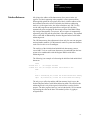
r68 is a two-pass assembler. During the first pass through the source
program, the symbol table is created by scanning each line in order to
identify symbolic name definitions. During the second pass, machine
language instructions and data values are placed in the relocatable object
file. The linker combines previously assembled relocatable object files in a
separate pass.
The linker (l68) takes any number of program sections and/or library
sections and combines them into a single executable OS-9 program. Global
data and program references are automatically resolved during the linking
process. The output of the linker is a binary executable file in the standard
OS-9 memory module format. The linker also generates the appropriate
module header for the program.
Important: For detailed information about memory modules refer to the
OS-9 Technical Manual.
Rdump
rdump is a program you can use to examine the contents of library files.
The syntax for rdump is:
rdump {<rof>} [<opts>]
<rof> must be a relocatable object file library. It usually has a suffix of
.r or .l.
1-1
Chapter 1
Basic Information About Assembler
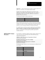
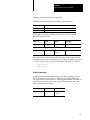
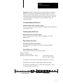
The rdump options are:
The Assembly Language
Program Development
Process
Option:
Description:
–a
Turns on all options: displays global symbols, local relocation
information, and external references
–g
Displays the defined global symbols.
–l
Scans library for forward reference conflicts.
–o
Displays the local relocation information.
–r
Displays the external references.
–r
Displays the external references.
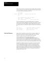
Writing and testing assembly language programs using r68 and l68
involves a basic edit, assemble, link, and test cycle. The assembler and
linker can simplify this process if programs are written in sections that can
be assembled separately, then linked together to form the entire program. If
one program section must be changed for any reason, then only the revised
section has to be reassembled.
The following is a summary of the steps involved in the assembly language
development process:
1-2
1.
Create a source program file using the text editor.
2.
Run the assembler (r68) to translate the source file(s) to a relocatable
object module(s).
3.
If necessary, use the text editor to correct any errors reported by r68
in the offending source file and repeat step 2.
4.
Combine all required relocatable modules using the linker (l68). If
the linker reports errors, correct them and repeat step 2.
5.
Run and test the program. The OS-9 system-state debugger or user
debugger (debug) is frequently used to test programs.
6.
If bugs are found in the program, use the text editor to correct the
source file and then repeat the above steps.
Chapter 1
Basic Information About Assembler
Running r68
r68 is a command program that you can run from the shell, from a shell
procedure file, etc. The file and memory module names are r68. The r68
command line syntax is:
r68 <file_name> [<option(s)>]
Important: r68020 is the name for the respective command program used
with the 68020 assembler. The syntax for r68020 is the same as above.
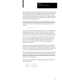
The <file_name> can be followed by an option list. This allows you to
control various factors such as object file or listing generation, listing
format control, etc. An option list contains one or more options separated
by spaces or commas. An option is turned on by its presence in the list
preceded by a hyphen (–). Two hyphens (––) followed by an option turns
off the function. If an option is not expressly given, the assembler will
assume a default condition for it.
Important: Some command line options can be overridden by an opt
statement within the source program.
By default, the output of r68 is directed to the standard output path (usually
the terminal display). It may optionally be redirected to another pathlist,
such as a printer, a disk file, or a pipe to another program. Output
redirection is handled by the shell and not the assembler itself.
r68 automatically handles memory allocation for its working data area.
Most of the data area memory is needed for the symbol table. r68 will
request memory as needed up to the maximum available memory.
The following are typical r68 command lines. They are functionally
identical, but the second command uses an alternative way of
combining options:
r68 prog5
–l –s ––c >/p
r68 prog5 –ls ––c >/p
In this example, the source program is read from the file prog5. The
options l and s are turned on, and c is turned off.
1-3
Chapter 1
Basic Information About Assembler
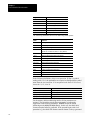
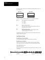
r68 Options
Up to 10 options are allowed on the command line. Each option is
specified by a single letter preceded by a single hyphen (–) or two hyphens
(––). Use a single hyphen (–) to turn on an option and two hyphens (––) to
turn off an option.
Option:
Description:
–a[=]<sym>[=<val>]
Allows a symbol to be defined before the assembly begins. The symbol is
defined as if it appeared as the label on a set directive. If a value is given,
the label is set to that value. Otherwise, the default value of 1 is assumed.
This option is most useful with the ifdef/ifndef directives.
.–c
Lists conditional assembly lines in an assembler listing. By default, this
option is off.
–d <num>
Sets the number of lines per page for listing to <num>. Default is 66.*
–e
Suppresses printing of errors. (Default off)
–f
Uses a form feed for page eject, instead of line feeds. Uses form feed for
top of form. (Default off)*
–g
Lists all generated code bytes. (Default off)*
–l
Writes a formatted assembler listing to standard output. If not used, only
error messages are printed. (Default off)
–m=<num>
Specifies machine assembler to be used: 0 = 68000/68020 (Default).
–n
Omits line numbers from the assembler listing. This allows more room
for comments.*
–o=<path>
Writes the relocatable output to the specified file (must be a mass storage
file). (Default off)
–q
Suppresses warnings and nonfatal messages (quiet mode). (Default off)
–s
Prints the symbol table at the end of an assembly listing. (Default off)
–v
Displays assembler Version and Edition number on standard error path.
–x
Prints macro expansion in assembler listing. (Default off)*
* These options do not make sense unless the –l option is also used.
Input File Format
reads the specified assembly source code file for its input. Each line in
the file is a text string terminated by an end-of-line (return) character. The
maximum length of an input line is 256 characters.
r68
An input line is made up of one to four fields separated by spaces and/or
tabs. The following fields may be used:
a label field (optional)
an operation field
an operand field containing 0 or more operands depending on the
operation
a comment field (optional)
Important: There are also two special cases:
An asterisk (*) in the first character position indicates a comment line.
The entire line is printed in the listing, but is not otherwise processed.
Blank lines are also included in the listing, but are likewise ignored.
1-4
Chapter 1
Basic Information About Assembler
Label Fields
The label field begins in the first character position of the line. Labels are
required by some statements (equ and set). Labels are not allowed on
others (for example, assembler directives such as spc, ttl, etc.).
The first character of the line must be a space or tab if the line does not
contain a label. If the label is present, the assembler defines it as the
address of the first byte of where the instruction’s object code will be
assigned. The exceptions to the rule are labels on set and equ statements.
These are assigned the operand field value.
When a symbolic name in the label field of a source statement is followed
by a colon (:), the name is known globally by all modules that are linked
together. Because the label is known globally, a branch or jump can be
done to a location in another module. For a global variable, the data offset
can be referred to by other modules.
If no colon appears after the label, the label will be known only in the psect
where it is defined. Care must be taken to access the labels in the
appropriate context.
The label must be a legal symbolic name consisting of from 1 to 256
uppercase or lowercase characters, decimal digits, the dollar ($), period (.),
or underline (_) characters. The first character may not be a dollar sign,
period, or digit. Upper and lower case characters are distinct.
Labels (and names in general) must be unique. They cannot be defined
more than once in a program (except when used with the set directive).
Labels on set and equ statements are assigned the operand field value.
These statements allow any value to be associated with a symbolic name.
The assembler determines the “type” of a label from the instruction
associated with that label. If no instruction or directive is specified for a
label in a vsect, the label type is initialized data; elsewhere the label type is
that assigned to code. Whenever possible, however, labels should be placed
on the same line as the instruction or directive with which they
are associated.
The Operation Field
The operation field specifies the machine language instruction or
assembler directive statement mnemonic name. It immediately follows the
label field. It is separated from the prior field by one or more spaces. r68
accepts instruction mnemonic names in either uppercase or
lowercase characters.
1-5
Chapter 1
Basic Information About Assembler
Instructions cause two or more bytes of object code to be generated
depending on the specific instruction and addressing mode. Some
assembler directive statements (such as dz and dc) also cause object code
to be generated.
Many 68000 instructions require a size attribute (for example, move.b
d0,d1 or move.w d1,(sp)). If no size attribute is specified, a word (.w) is
assumed. For example, move d0,d1 is a word move. Some instructions,
however, have no choice of size attribute. In this case, no size attribute
is allowed.
Operand Field
The operand field follows the instruction field. They must be separated by
at least one space or tab. Some instructions do not use an operand field.
Other instructions and assembler directives require one to specify an
addressing mode, operand address, and/or parameters. Some require a
source operand and a destination operand.
Important: See the specific instruction and assembler directive
descriptions for the operand format, if any.
Comment Field
The last field of the source statement is the optional comment field. It can
be used to include a descriptive comment in the source statement. This
field is not processed other than being copied to the program listing.
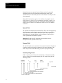
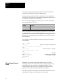
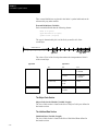
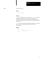
Assembly Listing Format
If the –l option is given in the r68 command line, a formatted assembly
listing is written to the standard output path. The output listing has the
following format:
00e6 64d2
00ea=b27c
+
label
bcc.s
cmp.w
label10
#E$EOF,d1
copy result
Comment field
Start of Operand Field
Start of Instruction Field
Start of Label Field
A + symbol here indicates a macro expansion
Start of Object Code Bytes
An = here indicates operand has an external reference
Location Counter Value
1-6
Chapter 1
Basic Information About Assembler
Evaluation of Expressions
Operands of many instructions and assembler directives can include
numeric expressions in one or more places. The assembler can evaluate
expressions of almost any complexity using a form similar to the algebraic
notation used in programming languages such as BASIC and FORTRAN.
Expressions consist of operands and operators. Operands are symbolic
names or constants. Operators specify an arithmetic or logical function. All
assembler arithmetic uses long word (internally, 32 bit binary) signed or
unsigned integers in the range of 0 to 4294967295 for unsigned numbers,
or −2147483648 to +2147483647 for signed numbers.
In some cases, expressions must result in a value which must fit in one
byte (for example, 8-bit displacement in branch instructions). Therefore,
they must be in the range of 0 to 255 for unsigned values and −128 to 127
for signed values. If the result is outside of this range, an error message
will be returned. Instructions that require a 16 bit value must result in a
value within the range of 0 to 65535 (unsigned) or −32768 to
+32767 (signed).
Expressions are evaluated from left-to-right using the algebraic order of
operations (that is, multiplications and divisions are performed before
additions and subtractions). Parentheses can be used to alter the natural
order of evaluation.
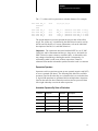
Expression Operands
The following items may be used as operands within an expression:
Decimal Numbers
An optional minus sign followed by one to twelve digits. For example:
100
–999999
3164765
0
–32767
12
Hexadecimal Numbers
A dollar sign ($ or 0x) followed by one to eight hexadecimal characters
(0-9, AF or a-f). For example:
$EC00
$3
$1000
$0300
0xFFFF
0xDEADFACE
Binary Numbers
A percent sign (%) followed by one to sixteen binary digits (0 or 1).
For example:
%0101
%10101010
%1111000011110000
1-7
Chapter 1
Basic Information About Assembler
Floating Point Numbers
Specify floating point numbers in the following format (the exponent may
be specified with either an upper or lower case e):
[–]digits[.digits[e[+/–][digits]
The range for floating point numbers is +/–2.2*10^–308 to +/–1.8*10^308.
For example:
–1.
–1.36E–124
10.5
1e5
106352.671e4 123456789
Character Constants
A single character enclosed by single quotes (’). For example:
’X’
’c’
’5’
Symbolic Names
One to nine characters consisting of:
Character:
Description:
upper or lower case letters
(A-Z, a-z)
digits
(0-9)
Special characters:
underscore
_
at sign
@
the dollar sign
$
period
.
The first character cannot be a digit, a dollar sign, or a period.
Symbolic names ending with a 68020 legal size specifier can cause
ambiguities in the 68020 extended addressing modes. For example, to
distinguish the label maxval.l from the symbol maxval with the size
attribute of long, use (maxval).l.
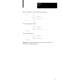
Location Counter Symbols
The asterisk (*) and period (.) characters are two special symbols that
represent the assembler’s internal location counters.
The asterisk character represents the value of the current location counter
before the instruction assembled. The location counter in use depends on
the vsect/psect block the assembler is currently processing. If the current
block is within a psect but not in a vsect, “*” contains the value of the code
location counter. If the current block is within a vsect, “*” contains the
value of the non-remote initialized data counter or the remote initialized
data counter as specified by the vsect [remote] parameter. For more
information refer to the section on the VSECT directive.
1-8
Chapter 1
Basic Information About Assembler
The “*” is often used in expressions to calculate distances. For example:
0000 0000 lbl_1:
00000000
0000
0008 fff8 lbl_2
000a 0004 lbl_3
000c fffe lbl_4
000e 000e lbl_5
dc.b
0,0,0,0,0,0,0,0
dc.w
dc.w
dc.w
dc.w
lbl_1–*
lbl_5–*
*–lbl_5
*–lbl_1
;distance
;distance
;distance
;distance
from
from
from
from
here to lbl_1
here to lbl_5
lbl_5 to here
lbl_1 to here
The period character is used to represent the current value of the offset
origin. The “offset org” is initialized by the ORG directive and is used by
the DO and LO directives. For more information, refer to the individual
descriptions of the DO, LO, and ORG directives.
Important: The expressions associated with the REPT, ds, dz, IF, SPC,
COM, DO, and LO statements and the type, lang, attr rev, and stack size
PSECT directives must evaluate to constant values. A relocatable result
may change when linking or loading the module. Consequently, if a
relocatable symbol is used in one of these expressions, it must be
subtracted from another relocatable symbol so that the result is a constant.
Expression Operators
Operators used in expressions operate on one operand (negative and NOT)
or on two operands (all others). The following table shows the available
operators, listed in the order they are evaluated relative to each other; that
is, logical OR operations are performed before multiplications. Operators
listed on the same line have identical precedence and are processed from
left to right when they occur in the same expression.
Assembler Operators By Order of Evaluation
Character:
Description:
Character:
Description:
–
negative
^
logical NOT
&
logical AND
!|
logical OR
*
multiplication
/
division
+
addition
–
subtraction
<<
shift left
>>
shift right
1-9
Chapter 1
Basic Information About Assembler
Logical operations are performed bitwise; that is, the logical function is
performed bit-by-bit on each bit of the operands. Division and
multiplication functions assume unsigned operands, but subtraction and
addition functions work on signed (2’s complement) or unsigned numbers.
Division by zero or multiplication resulting in a product larger than
4294967295 have undefined results and are reported as errors.
Expressions Involving External Symbols
An external symbol is a symbol whose value is not known at the time the
program section is assembled. The actual values of external references
must be inserted later when the program is linked.
The linker can resolve a limited number of expressions involving external
references. These expressions can consist only of simple addition and
subtraction operations involving two operands at most. The following
expression forms involving external references are supported. All other
forms are illegal.
External + Absolute
External – Absolute
External – External
The linker performs subtraction by negating one operand and then adding
it to the other operand. This method can cause problems on signed values
of either word or byte length as the linker may report over/underflow
errors. Therefore, care should be taken to minimize the complexity of
expressions involving external names.
Symbolic Names
A symbolic name consists of up to 256 of the following characters:
Symbolic name:
Description:
alphanumerics
a-z, A-Z, 0-9
underscore
_
at sign
@
the dollar sign
$
period
.
The first character cannot be a digit, dollar sign, or a period. The following
are examples of legal symbol names:
HERE
Q1020.1
1-10
there
t$integer
SPL030
L.123.X
PGM_A
a002@
Chapter 1
Basic Information About Assembler
Important: r68 does not match lowercase letters to uppercase letters. The
names val_A and VAL_A are considered different names.
Symbolic names ending with a 68020 legal size specifier can cause
ambiguities in the 68020 extended addressing modes. For example, to
distinguish the label maxval.l from the symbol maxval with the size
attribute of long, use (maxval).l.
The following examples are illegal symbol names:
This symbol name:
is illegal because:
2move
starts with a digit
lbl#123
the pound sign (#) is not a legal name character.
Names are defined when first used as a label on an instruction or directive
statement. They must be defined exactly one time in the program, with the
exception of set labels. If a name is redefined (that is,used as a label more
than once), an error message is printed on subsequent definition(s).
If a symbolic name is used in an expression and has not been defined, the
name is assumed to be external to the psect. Information will be recorded
about the reference so the linker can adjust the operand accordingly.
However, external names cannot appear in operand expressions for
assembler directives.
68000 Assembly Language
Mnemonics
The assembler uses Motorola standard assembly language mnemonics and
syntax. For more specific information about individual instructions,
consult the following books:
M68000 16/32 Bit Microprocessor Programmer’s Manual
Prentice-Hall, Fourth Edition
MC68020 32 Bit Microprocessor User’s Manual
Prentice-Hall, Second Edition
MC68881 Floating-Point Coprocessor User’s Manual
Prentice-Hall, First Edition
The following register names are reserved and cannot be redefined or used
out of context:
Register name:
Definition:
An
Address register n
Dn
Data register n
pc or pcr
Program counter
sr
Status register
ccr
Condition codes
ssp
Supervisor stack pointer
usp
User stack pointer
1-11
Chapter 1
Basic Information About Assembler
Register name:
Definition:
sfc
Source function code
dfc
Destination function
cacr
Cache control register
vbr
Vector base register
caar
Cache address register
msp
Master stack pointer
isp
Interrupt stack pointer
The following definitions are used in addressing mode syntax:
Mode:
Definition:
Dn
Data Register Direct
An
Address Register Direct
Rn
Data or Address Register Direct
Xn.s
Index Register n (either address or data).s indicates the index
register size. It is either .w (word) or .l (long, default)
(An)
Address Register Indirect
(An)+
Address Register Indirect with Postincrement
–(An)
Address Register Indirect with Predecrement
d(An)
Address Register Indirect with Offset
d(An,Xn.s)
Address Register Indirect with Index
(xxx).w
Absolute Short
(xxx).l
Absolute Long
d(pc)
Program Counter Indirect with Offset
d(pc,Xn.s)
Program Counter Indirect with Index
#xxx
Immediate Data
In the following definitions, (disp) is an expression. If disp is a symbol
ending with .w or .l, the parentheses are required to distinguish the symbol
name from the size extension. *S is an optional scale factor. If *S is used,
it must be *1, *2, *4 or *8.
Expression:
((disp).w,An)
((disp).s,An,Xn.s*S)
([(disp).s,An],Xn.s*S,(disp).s)
([(disp).s,An,Xn.s*S],(disp).s)
Definition:
Address Register Indirect with Offset
Address Register Indirect with Index (Base Displacement)
Memory Indirect Post-indexed
Memory Indirect Pre-indexed
For the memory indirect addressing modes, all four parameters are
optional. The assembler encodes the proper modes to indicate the
suppression of the missing parameters. r68020 accepts the 68000
addressing modes d(An) and d(An,Xn.s). In this case, the 68020 brief
format extension format is generated. If the operand begins with a left
parenthesis ((), the 68020 full format extension format is always generated.
1-12
Chapter 1
Basic Information About Assembler
Extension length/modes:
Brief format
Full format with 32-bit displacement
Full format with 16-bit displacement
Full format with sized index register
Memory Indirect Post-indexed (no outer disp)
Memory Indirect (no inner or outer disp)
Memory Indirect (no inner, outer disp or index)
Example:
clr.b var(a6)
clr.b (var,a6)
clr.b ((var).w,a6)
clr.b (var,a6,d0.w*2)
clr.b ([(var).w,a4])
clr.b ([a4])
clr.b (d0)
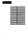
The following table contains the condition codes used with the assembler
instructions described in this chapter:
Mnemonic:
Condition:
Explanation:
cc
!C
Carry clear
cs
C
Carry set
eq
Z
Equal
ge
N.V+!N.!V
Greater than or equal
gt
N.V.Z+!N.!V.!Z
Greater than
hi
!C.!Z
Higher
hs
!C
Higher or the same
le
Z+N.!V+!N.V
Less than or equal
lo
C
Lower
ls
C+Z
Lower or the same
lt
N.!V+!N.V
Less than
mi
N
Minus
ne
!Z
Not equal
pl
!N
Plus
vc
!V
Overflow clear
vs
V
Overflow set
The following condition code bit symbols are used in the above table:
Symbol:
Description:
N
negative
V
overflow
Z
zero
C
carry
1-13
Chapter 1
Basic Information About Assembler
The following instruction mnemonic summary uses these conventions:
Convention:
Description:
<data>
Immediate data of appropriate size
.s
Indicates .w, .l, or .b The default is .w, if the size is not explicitly
given.
<ea>
Any legal addressing mode for the instruction
Mnemonic:
Description:
abcd Dy,Dx
Add decimal with Extend Register
abcd –(Ay),–(Ax)
Add decimal with Extend Memory
add.s <ea>,Dn
Add binary register
add.s Dn,<ea>
Add binary memory
adda.s <ea>,An
Add address (.w or .l only)
addi.s #<data>,<ea>
Add immediate
addq.s #<data>,<ea>
Add quick
addx.s Dy,Dx
Add extended register
addx.s –(Ay),–(Ax)
Add extended memory
and.s <ea>,Dn
And logical register
and.s Dn,<ea>
And logical memory
andi.s #<data>,<ea>
And immediate
andi #<data>,ccr
And immediate to condition code
andi #<data>,sr
And immediate to status register
In the following 3 instructions, the shift direction (d) may be l (for left) or r
(for right).
1-14
Mnemonic:
Description:
asd.s Dx,Dy
Arithmetic Shift register
asd.s #<data>,Dy
Arithmetic Shift immediate register
asd <ea>
Arithmetic Shift memory
Chapter 1
Basic Information About Assembler
In the following instructions, cc represents the branch condition code.
Mnemonic:
bcc <label>
bcc.s <label>
bcc.b <label>
bcc.w <label>
bcc.l <label>
bchg.s Dn,<ea>
bchg.s #<data>,<ea>
bclr.s Dn,<ea>
bclr.s #<data>,<ea>
bfchg <ea>{offset:width}
bfclr <ea>{offset:width}
bfexts <ea>{offset:width},Dn
bfextu <ea>{offset:width},Dn
bfffo <ea>{offset:width},Dn
bfins Dn,<ea>{offset:width}
bfset <ea>{offset:width}
bftst <ea>{offset:width}
bkpt #<data>
bra <label>
bra.s <label>
bra.b <label>
bra.w <label>
bra.l <label>
bset.s Dn,<ea>
bset.s #<data>,<ea>
bsr <label>
bsr.s <label>
bsr.b <label>
bsr.w <label>
bsr.l <label>
btst.s Dn,<ea>
btst.s #<data>,<ea>
callm #<data>,<ea>
cas Dc,Du,<ea>
cas2 Dc1:Dc2,Du1:Du2,(Rn1):(Rn2)
chk <ea>,Dn
chk.l <ea>
chk2.s <ea>,Rn
clr.s <ea>
cmp.s <ea>,Dn
cmpa.s <ea>,An
cmpi.s #<data>,<ea>
cmpm.s (Ay)+,(Ax)+
cmp2.s <ea>,Rn
Description:
Conditional branch word displacement
Conditional branch byte displacement
Conditional branch byte displacement
Conditional branch word displacement
Conditional branch long displacement
Test bit and change register (.b or .l)
Test bit and change immediate (.b or .l)
Test bit and clear register (.b or .l)
Test bit and clear immediate (.b or .l)
Test Bit Field and Change
Test Bit Field and Clear
Extract Bit Field Signed
Extract Bit Field Unsigned
Find First One in Bit Field
Insert Bit Field
Set Bit Field
Test Bit Field
Breakpoint
Branch word displacement
Branch byte displacement
Branch byte displacement
Branch word displacement
Branch long displacement
Test bit and set register (.b or .l)
Test bit and set immediate (.b or .l)
Branch subroutine word displacement
Branch subroutine byte displacement
Branch subroutine byte displacement
Branch subroutine word displacement
Branch subroutine long displacement
Test bit register (.b or .l)
Test bit immediate (.b or .l)
Call Module
Compare and Swap with Operand
Compare and Swap with Operand
Check register against bounds
Check register against bounds
Check register against bounds (.b, .w, or .l)
Clear operand
Compare data register
Compare address register
Compare immediate
Compare memory
Compare register against bounds (.b, .w or .l)
1-15
Chapter 1
Basic Information About Assembler
cc in the following instruction represents the branch condition code.
1-16
Mnemonic:
Description:
dbcc dn,<label>
Test condition, decrement and branch
divs <ea>,Dn
Signed divide
divu <ea>,Dn
Unsigned divide
divs.w <ea>,Dn
Signed Divide – 32/16”16r:16q
divs.l <ea>,Dq
Signed Divide – 32/32”32q
divs.l <ea>,Dr:Dq
Signed Divide – 64/32”32r:32q
divsl.l <ea>,Dr:Dq
Signed Divide – 32/32”32r:32q
divu.w <ea>,Dn
Unsigned Divide – 32/16”16r:16q
divu.l <ea>,Dq
Unsigned Divide – 32/32”32q
divu.l <ea>,Dr:Dq
Unsigned Divide – 64/32”32r:32q
divul.l <ea>,Dr:Dq
Unsigned Divide – 32/32”32r:32q
eor.s Dn,<ea>
Exclusive OR
eori.s #<data>,<ea>
Exclusive OR immediate
eori #<date>,ccr
Exclusive OR condition code
eori #<data>,sr
Exclusive OR status register
exg Rx,Ry
Exchange registers
extb.l Dn
Extend byte to longword
ext.s Dn
Sign extend (.w or .l)
jmp <ea>
Jump
jsr <ea>
Jump to subroutine
lea <ea>,An
Load effective address
link An, #<displacement>
Link and allocate
link.l An, #<displacement>
Link and allocate (long displacement)
Chapter 1
Basic Information About Assembler
In the following three instructions, the shift direction (d) may be l (for left)
or r (for right).
Mnemonic:
Description:
lsd.s Dx,Dy
Logical shift data
lsd.s #<data>,Dy
Logical shift immediate
lsd <ea>
Logical shift memory
move.s <ea>,<ea>
Move from source to destination
move ccr,<ea>
Move from condition codes. This instruction is not available
on the 68000. The OS-9 Kernel will emulate this instruction
on the 68000 to allow user-state code to be easily
transported from 68000 to 68010/68020.
move <ea>,ccr
Move to condition codes
move <ea>,sr
Move to status register
move sr,<ea>
Move from status register. This is privileged on the
68010/68020. Avoid this instruction in programs that are to
execute in user-state.
move usp,An
Move from user stack pointer
move An,usp
Move to user stack pointer
movea.s <ea>,An
Move address (.w or .l)
movem.s <ea>,<reg list>
Move multiple
Examples: d0
d0 only
d0/d4/a5
d0,d4,a5
d0–d7/a0–a5
d0 through d7,
a0 through a5
movep.s dx,d(Ay)
Move peripheral data (.w or .l) from register to memory
movep.s d(Ay),dx
Move peripheral data (.w or .l) from memory to register
moveq.l #<data>,dn
Move quick
1-17
Chapter 1
Basic Information About Assembler
For the next instructions, the following are valid registers for Rc: SFC,
DFC, CACR, USP, VBR, CAAR, MSP, and ISP.
1-18
movec Rc,Rn
Move from control register
movec Rn,Rc
Move to control register
Mnemonic:
Description:
moves.s Rn,<ea>
Move to address space
moves.s <ea>,Rn
Move from address space
muls <ea>,Dn
Signed multiply
mulu <ea>,Dn
Unsigned multiply
muls.w <ea>,Dn
Signed Multiply 16 x 16”32
muls.l <ea>,Dl
Signed Multiply 32 x 32”32
muls.l <ea>,Dh:Dl
Signed Multiply 32 x 32”64
mulu.w <ea>,Dn
Unsigned Multiply 16 x 16”32
mulu.l <ea>,Dl
Unsigned Multiply 32 x 32”32
mulu.l <ea>,Dh:Dl
Unsigned Multiply 32 x 32”64
nbcd <ea>
Negate decimal with extend
neg.s <ea>
Negate
neg.s <ea>
Negate with extend
nop
No operation
not.s <ea>
Logical complement
or.s <ea>,Dn
Inclusive OR register
or.d Dn,<ea>
Inclusive OR memory
ori.s #data>,<ea>
Inclusive OR immediate
ori #<data>,ccr
Inclusive OR condition codes
ori #<data>,sr
Inclusive OR status register
pack –(Ax),–(Ay),#<adjust>
Pack BCD
pack Dx,Dy,#<adjust>
Pack BCD
pea <ea>
Push effective address
reset
Reset external devices
Chapter 1
Basic Information About Assembler
In the following 6 instructions, the shift direction (d) may be l (for left) or r
(for right).
Mnemonic:
Description:
rod.s Dx,Dy
Rotate without extend register
rod.s #<data>,dy
Rotate without extend immediate
rod <ea>
Rotate without extend memory
roxd.s Dx,Dy
Rotate with extend register
roxd.s #<data>,dy
Rotate with extend immediate
roxd <ea>
Rotate with extend memory
rte
Return from exception
rtr
Return and restore condition codes
rts
Return from subroutine
rtd #<displacement>
Return and deallocate
rtm Rn
Return from module
sbcd Dy,Dx
Subtract decimal with extended register
sbcd –(Ay),–(Ax)
Subtract decimal with extended memory
cc in the following instruction represents the branch condition code.
Mnemonic:
Description:
scc <ea>
Set according to conditional registers
stop #<data>
Load and stop
sub.s <ea>,Dn
Subtract binary register
sub.s Dn,<ea>
Subtract binary memory
suba.s <ea>,An
Subtract address (.w or .l)
subi.s #<data>,<ea>
Subtract immediate
subq.s #<data>,<ea>
Subtract quick
subx.s Dy,Dx
Subtract with extend register
swap Dn
Swap register halves
tas <ea>
Test and set operand
trap #<vector>
Trap
trapv
Trap on overflow
In the following three instructions, cc uses standard condition codes.
Mnemonic:
Description:
trap cc
Trap on Condition
trap cc.w #<data>
Trap on Condition
trap cc.l #<data>
Trap on Condition
tst.s <ea>
Test operand
unlk An
Unlink
unpk –(Ax),–(Ay),#<adjust>
Unpack BCD
unpk Dx,Dy,#<adjust>
Unpack BCD
1-19
Chapter 1
Basic Information About Assembler
68881 Floating Point
Coprocessor Mnemonics
The 68020 assembler (r68020) recognizes instructions and addressing
modes referencing the 68881 floating point coprocessor. This section
applies only to the 68020.
The following register names are reserved for referencing the 68881 and
cannot be redefined or used out of context:
Register name:
Definition:
FPn
Floating point register (0-7)
FPcr
Floating point control register
FPsr
Floating point status register
FPiar
Floating point instruction address register
The assembler recognizes the following floating operand data
format extensions:
Extension:
Description:
B
Byte Integer
W
Word Integer
L
Longword Integer
S
Single Precision Real
D
Double Precision Real
X
Extended Precision Real
The P (packed decimal real) data format is not supported.
Floating point constants can be given when a floating point instruction
indicates immediate addressing. Floating point constants can be given in
decimal format or left-justified hexadecimal format. The size of the
immediate data value is determined from the data format extension given
on the floating point instruction. Single precision values are stored
internally as double precision and converted to single precision before
storing into the instruction. Extended precision constants can be given only
as hexadecimal values.
Floating Point Examples
Example:
Description:
fadd.l #10,fp0
Long integer value of 10 is converted to extended and added
to fp0.
Same as above.
fadd.l #0x10,fp0
fadd.s #5,fp0
fadd.s #0x40A0,fp0
fadd.d #1.3e4,fp0
1-20
Single precision value of 5 is converted to extended and added
to fp0.
Same as above.
fadd.d #0x40C964,fp0
Double precision value of 130000 is converted to extended
precision and added to fp0.
Same as above.
fadd.x #0x3ff,fp0
Extended value of 3FF000000000000 is added to fp0.
Chapter 1
Basic Information About Assembler
Floating point expressions are not supported.
The 68881 instruction mnemonic summary uses the notation:
Notation:
Description:
<data>
Immediate data of appropriate size
<ea>
Any legal addressing mode for the instruction
In the 68881 instruction mnemonic summary, the following format
describes the instructions:
Mnemonic:
Format:
Syntax:
Description:
<inst>
b,w,l,s,d or x
<syntax>
<description of instruction>
b,w,l,s,d,x
<ea>,FPn
Add
x
FPm,FPn
For example:
fadd
The example above describes the fadd instruction. It shows that the fadd
instruction may take the form fadd.b, fadd.w, fadd.l, etc. and use the syntax
<ea>,FPn. fadd.x, however, may use the syntax FPm,FPn. For example:
fadd.x fp0,fp1
fadd.x #5,fp0
Dyadic Instructions
Dyadic floating point instructions require two source operands. The first
source operand can be any effective address or a floating point register.
The second source operand must be a floating point register. The results of
the operation are stored in this same register. The general format of the
dyadic instructions is as follows:
Mnemonic:
Format:
Syntax:
<dyadic inst>
b,w,l,s,d,x
<ea>,FPn
x
FPm,FPn
1-21
Chapter 1
Basic Information About Assembler
The following 68881 floating point instructions use the above
dyadic syntax:
Mnemonic:
Description:
fadd
Add
fcmp
Compare
fdiv
Divide
fmod
Modulo remainder
fmul
Multiply
frem
IEEE remainder
fscale
Scale exponent
fsgldiv
Single precision divide
fsglmul
Single precision multiply
fsub
Subtract
Monadic Instructions
Monadic floating point instructions require only one source operand. These
instructions can specify a source and destination operand. The source
operand can be any effective address or a floating point register. The
operation is performed on the source operand and the result is placed in the
destination operand, which is always a floating point register. If the source
operand is an effective address, any operand format can be given. If the
source operand is a floating point register, only the x format is allowed. If
no destination floating point register is given, the operation is performed
on the given register and the resulting value is stored in the same register.
The general format of the monadic instructions is as follows:
1-22
Mnemonic:
Format:
Syntax:
<monadic inst>
b,w,l,s,d,x
<ea>,FPn
x
FPm,FPn
x
FPn
Chapter 1
Basic Information About Assembler
The following 68881 floating point instructions use the above
monadic syntax:
Mnemonic:
Description:
fabs
Absolute value
facos
Arc cosine
fasin
Arc sine
fatan
Arc tangent
fatanh
Hyperbolic arc tangent
fcos
Cosine
fcosh
Hyperbolic cosine
fetox
ex
fetoxm1
e(x–1)
fgetexp
Get exponent
fgetman
Get mantissa
fint
Integer part
fintrz
Integer part; round to zero
flog10
Log10
flog2
Log2
flogn
Loge
flognp1
Loge–1
fneg
Negate
fsin
Sine
fsinh
Hyperbolic sine
fsqrt
Square root
ftan
Tangent
ftanh
Hyperbolic tangent
ftentox
10x
ftwotox
2x
1-23
Chapter 1
Basic Information About Assembler
Data Movement Instructions
Mnemonic:
Format:
Syntax:
Description:
fmove
x
FPm,FPn
Floating move
b,w,l,s,d,x
<ea>,FPn
b,w,l,s,d,x
FPm,<ea>
l
<ea>,FPcr
l
FPcr,<ea>
fmovecr
fmovem
#ccc,FPn
Move from constant ROM
l,x
<flist>,<ea>
l,x
<ea>,<flist>
x
Dn,<ea>
x
<ea>,Dn
Move multiple floating registers. <flist>
is a sequence of floating registers.
Each register in the list is separated by
a slash (/). Consecutive registers may
be grouped using a hyphen (–)
between the beginning and ending
registers. If l format is given, only
FPCR, FPSR or FPIAR are allowed. If x
is given, only FP0–FP7 are allowed.
Program Control Instructions
Mnemonic:
Format:
Syntax:
Description:
fbcc
<label>
Branch on floating condition ***
fdbcc
Dn,<label>
Decrement and branch on floating condition ***
fnop
No operation
fscc
<ea>
Set on floating condition ***
ftst
<ea>
Test floating operand
*** This instruction uses floating point condition predicates for “cc”
System Control Operations
Mnemonic:
Format:
Syntax:
Description:
frestore
<ea>
Restore internal state
fsave
<ea>
Save internal state
ftrapcc
#<data>
Trap on floating condition ***
*** This instruction uses floating point condition predicates for “cc”
1-24
Chapter 1
Basic Information About Assembler
The fsincos instruction is a special dual monadic instruction. Consequently,
two operands are given:
Mnemonic:
Format:
Syntax:
Description:
fsincos
b,w,l,s,d,x
<ea>,FPc:FPs
Simultaneous Sine and Cosine.
x
FPm,FPc:FPs
FPc is the resulting cosine value,
FPs is the resulting sine value.
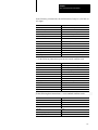
Floating Point Condition
Predicates used for CC
Mnemonic:
Description:
EQ
Equal
F
False
GE
Greater than or equal
GL
Greater or less than
GLE
Greater less or equal
GT
Greater than
LE
Less than or equal
LT
Less than
NE
Not equal
NGE
Not (greater than or equal)
NGL
Not (greater or less than)
NGLE
Not (greater less or equal)
NGT
Not (greater than)
NLE
Not (less than or equal)
NLT
Not (less than)
OGE
Ordered greater than or equal
OGL
Ordered greater or less than
OGT
Ordered greater than
OLE
Ordered less than or equal
OLT
Ordered less than
OR
Ordered
SEQ
Signaling equal
SF
Signaling false
SNE
Signaling not equal
ST
Signaling true
T
True
UEQ
Unordered or equal
UGE
Unordered or greater or equal
UGT
Unordered or greater than
ULE
Unordered or less or equal
ULT
Unordered or less than
UN
Unordered
1-25
Chapter 1
Basic Information About Assembler
Constant ROM Table
1-26
The following are offsets into the 68881 constant ROM that contain
useful values:
Offset:
Constant:
$00
PI
$0B
Log10(2)
$0C
e
$0D
Log2(e)
$0E
Log10(e)
$0F
0.0
$30
In2
$31
In10
$32
100
$33
101
$34
102
$35
104
$36
108
$37
1016
$38
1032
$39
1064
$3A
10128
$3B
10256
$3C
10512
$3D
101024
$3E
102048
$3F
104096
Chapter
2
Macros
Introduction to Macros
Identical or similar sequences of instructions may often be repeated in
different places in a program. Writing a sequence of instructions repeatedly
can be tedious if the sequence is long or must be used a number of times.
A macro is a definition of an instruction sequence that can be used
numerous places within a program. The macro is given a name which is
used similarly to any other instruction mnemonic. Whenever r68
encounters the name of a macro in the instruction field, it outputs all the
instructions given in the macro definition. In effect, macros allow you to
create new machine language instructions.
For example, suppose a program frequently must perform left shifts. You
can define this two-instruction sequence as a macro. For example:
dasl
macro
asl.l d1
roxl.l d0
endm
do a shift left
The macro and endm directives specify the beginning and the end of the
macro definition, respectively. The label of the macro directive specifies
the name of the macro. In this example, the name is dasl. When r68
encounters the dasl macro, it can output code for asl and roxl. Normally,
only the macro name is listed, but you can use the –x option of r68 to cause
all instructions of the macro expansion to be listed.
Macros should not be confused with subroutines, although they are similar.
A macro repetitively duplicates an in line code sequence every time it is
used and allows some alteration of the instruction operands. Subroutines
appear exactly once and never change. Subroutines are called using special
instructions (bsr, jsr, and rts).
In those cases where macros and subroutines can be used interchangeably,
macros usually produce longer but slightly faster programs. Short macros
(6 bytes or less) are usually faster and shorter than subroutines because of
the overhead of the needed bsr and rts instructions.
Macros can be an important and useful programming tool that can
significantly extend r68’s capabilities. In addition to creating instruction
sequences, you can also use them to create complex constant tables and
data structures.
2-1
Chapter 2
Macros
ATTENTION: When you use macros, you should carefully
document them. Macros can impair the readability of a program
if they are used indiscriminately and unnecessarily. This can
make it extremely difficult to understand the program logic.
Macro Structure
A macro definition consists of three sections:
<name> macro * the macro statement assigns a name to the macro *
.
.
body
* the macro body contains the macro statements *
.
.
endm
* the endm statement indicates the end of the macro *
The macro name must be defined by the label given in the macro
statement. The name can be any legal assembler label. You can redefine
the 68000 instructions themselves by defining macros having identical
names. This gives r68 the capability to be used as a cross-assembler for
non-68000 processors by definition and/or redefinition of the instruction
set of the target CPU.
ATTENTION: Redefinition of assembler directives such as ds
can have unpredictable consequences.
The body of the macro can contain any number of legal r68 instructions or
directive statements including references to previously defined macros.
The last statement of a macro definition must be endm.
The text of macro definitions are stored on a temporary file created and
maintained by r68. This file has a 1K buffer to minimize disk accesses.
Therefore, programs that use more than 1K of macro storage space should
be arranged so that short, frequently used macros are defined first so they
are kept in the memory buffer instead of disk space.
2-2
Chapter 2
Macros
The body of a macro definition may contain a call to another macro. The
definition of a new macro within another, however, is not permitted. Macro
calls may be nested up to eight levels. For example, the following macro
consists of two iterations of the mac1 macro:
times2
mac1
mac1
endm
Macro Arguments
macro
Arguments permit variations in the expansion of a macro. For example,
you can use arguments to specify operands, register names, constants, or
variables in each occurrence of a macro.
A macro can have up to nine formal arguments in the operand fields. Each
argument consists of a backslash character and the sequence number of the
formal argument (\1, \2 ... \9). When the macro is expanded, each formal
argument is replaced by the corresponding text string actual argument
given in the macro call. You can use arguments in any part of the operand
field not in the instruction or label fields. Formal arguments can be used in
any order and any number of times.
For example, the macro below performs the typical instruction sequence to
an I$WritLn:
writ
macro
moveq #\1,d0
moveq #\2,d1
lea
\3(a6),a0
os9 I$WritLn
endm
Get path
Number of chars to write
Get address of buffer
This macro uses three arguments:
\1 for the path number
\2 for the number of characters to write
\3 for the address of the buffer.
When writ is referenced, each argument is replaced by the corresponding
string given in the macro call, for example:
writ 1,2,Buf
The macro call above is expanded to the code sequence:
moveq #1,d0
moveq #2.d1
lea
Buf(a6),a0
os9 I$Writln
2-3
Chapter 2
Macros
If an argument string includes special characters such as backslashes or
commas, the string must be enclosed in double quotes.
An argument may be declared null by omitting all or some arguments in
the macro call. This makes the corresponding argument an empty string so
no substitution occurs when it is referenced.
There are two special argument operators that are useful in constructing
more complex macros. They are:
Operator:
Description:
\Ln
Returns the length of the actual argument n, in bytes.
\#
Returns the number of actual arguments passed in the given macro call.
These special operators are most commonly used with r68’s conditional
assembly facilities to test the validity of arguments used in a macro call, or
to change the way a macro works according to the actual arguments used.
When macros are performing error checking, they can report errors using
the fail directive.
For example, you could expand the writ macro on the previous page for
error checking:
writ
macro
ifne \#–3
Must have exactly three arguments
fail writ: must have three arguments
endc
ifgt \L3–29
File name can be 1 - 29 chars
fail writ: File name too long
endc
moveq #\1,d0
Get path
path moveq #\2,d1
Number of chars to write
lea
\3(a6),a0
Get address of buffer
os9 I$WritLn
endm
Macro Automatic Internal
Labels
Sometimes it is necessary to use labels within a macro. If a macro
containing a label is to be used more than once, a method of generating
unique label names is required to avoid multiple definition errors. A
backslash followed by an at sign (\@) appearing in a label in a macro
expansion is replaced with a macro expansion serial number.
The macro expansion serial number is incremented each time the macro is
expanded and is unique to that particular macro expansion.
2-4
Chapter 2
Macros
Here is an example of a macro that uses unique labels:
test
macro
tst.b stat(a6)
beq.s t\@a
addq.l #1,count(a6)
t\@a
endm
The macro expands as follows:
tst.b stat(a6)
beq.s t00001a
addq.l #1,count(a6)
t00001a
The second expansion is:
tst.b stat(a6)
beq.s t00002a
addq.l #1,count(a6)
t00002a
Important: \@ simply expands to a number. Proper syntax must be
observed when constructing labels.
2-5
Chapter
3
Relocatable Program Sections
Relocatable Program
Sections
A primary purpose of r68 is to permit programs to be composed of
different segments that can be assembled separately.
Important: To clarify the following discussion, segments are synonymous
with source files.
OS-9 processes use at least two separate areas of memory: the program
object code in memory module format and a data area used for the
program’s variables and the stack. The linker (l68) combines all of the
segments into a single OS-9 memory module and a coordinated data
storage area. By using global symbolic names, code in each segment can
reference variables declared in other segments or may transfer program
control to labels in other segments.
When the assembler source program for each segment is written, it must be
divided into distinct sections for variable storage definitions (vsects) and
for program instructions (psects). The output of the assembler is a distinct
relocatable object file (ROF) containing the object code output plus
information about the variable storage declarations for the linker to use.
The linker reads the ROFs, assigns space in the data storage area, and
combines all the object code into a single executable memory module. As
it does so, it must alter the operands of instructions to refer to the final
variable assignments and must also adjust program control transfer
instructions that refer to labels in other segments.
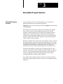
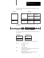
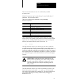
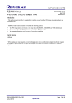
For example, if three segments called A, B, and C are processed by the
linker, the resulting memory allocation is shown in the simplified memory
map below.
3-1
Chapter 3
Relocatable Program Sections
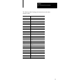
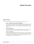
Figure 3.1
Executable Memory Module
Generated by l68
Module Header
Mainline segment
Segment A Object Code
These correspond to
each segment’s psects
Segment B Object Code
Segment C Object Code
Initialized Data Information
Generated by l68
CRC Check Value
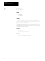
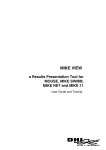
Figure 3.2
Process Data Area
Segment A Uninitialized Variables
*
Segment B Uninitialized Variables
These correspond
Segment C Uninitialized Variables
i
Segment A Initialized Variables
to each segment*s
vsects
Segment B Initialized Variables
Segment C Initialized Variables
Segment A Initialized Remote Variables
*
*
Segment B Initialized Remote Variables
These correspond
Segment C Initialized Remote Variables
i
Segment A Uninitialized Remote Variables
remote vsects
Segment B Uninitialized Remote Variables
Segment C Unnitialized Remote Variables
3-2
to each segment*s
*
Chapter 3
Relocatable Program Sections
Program Section
Declarations: Psect and
Vsect
Most program statements are included in sections called psects and vsects
(program and variable sections, respectively).
A psect contains the program instructions and variable declarations. Each
source file may have only one psect. Global symbols (labels with a colon
(:) suffix) in this section are accessible from all other program segments.
Similarly, statements in this section can reference global symbols properly
defined in other program segments. Statements in this section may also
appear in linkage maps and symbolic debugger symbol lists. The psect is
terminated by a matching ends or endsect statement.
Global and local variable storage are declared inside one or more vsects
within the psect. Vsects are usually nested within a psect, but vsects cannot
be nested within themselves.
A variable declaration section begins with a vsect statement and ends with
an ends or endsect statement. There are two types of variable declarations:
initialized and uninitialized. These correspond to the assembly language
storage allocation mnemonics dc and ds, respectively. l68 combines all
initialized variable declarations from all program segments into a single
initialized data memory area. Similarly, all the uninitialized data
declarations are combined into a single uninitialized data memory area.
There is a third type of vsect declaration regarding remote data. This vsect
accumulates large amounts (greater than 32K) of data declarations. The
linker places remote vsect declarations after the end of the initialized and
uninitialized data allocation. The size of the remote data area is limited
only by the amount of physical memory on the system.
Important: Instructions accessing the remote data area must use long
(32-bit) indexed addressing modes.
Certain types of statements can appear outside (usually before) the psect.
These are generally set and equ (and possibly the lo and do statements).
These declare symbolic constants and symbolic offsets. Labels on these
statements are local to the assembly of the source file and are not usable
during assembly of other program segments. Additionally, these statements
cannot reference any global symbols.
For example, the oskdefs file is intended to be included outside the psect of
each source program. Although technically a vsect can similarly appear
outside the psect, the usefulness of such a vsect is limited to defining the
expected type of an external symbol as a data area symbol because no
actual storage would be assigned to it by the linker.
3-3
Chapter 3
Relocatable Program Sections
Diagram of Typical Program Layout
nam example
ttl sections and declarations
labconstequ
space
equ
mode
set
use
1
$20
1
/h0/defs/oskdefs
Local constant definitions
Include local definitions file
psect nam,typ,rev,ed,stack,gblcode
vsect
gblunin:ds.l 1
gblinit:dc.b “string”,0
locunin ds.l 1
locinit dc.b “hello”,0
ends
gblcode:
move.l gblunin(a6),d0
lea gblinit(a6),a0
bsr.s intcode
bsr extcode
move.l d0,extdat(a6)
rts
indat
vsect
ds.l 1
ends
intcode rts
ends
Location Counters
Start of psect
Start of nested vsect
Global uninitialized data
Global initialized data
Local uninitialized data
Local initialized data
End of vsect
Global code label
Global uninitialized data reference
Global initialized data reference
Internal code reference
External code reference
External data reference
Start of nested vsect
Local uninitialized data
End of vsect
Local code label
End of psect
maintains a set of address counters that keep track of relative memory
addresses of object code, initialized data, uninitialized data, and remote
data. It is important to remember that location counter values are relative
and not the actual physical memory addresses. Actual memory locations
are not known until the program has been linked and loaded into memory.
r68
The psect statement resets the instruction and data location counters, and
assembles subsequent instructions into the ROF object code file. As object
code is generated, the instruction location counter is advanced accordingly.
An asterisk (*) symbol can be used in expressions to refer to the current
relative value of this counter.
3-4
Chapter 3
Relocatable Program Sections
The vsect statement causes r68 to use the variable (data) location counters
and places information about subsequently declared variables into the
appropriate ROF data description area. As variables are declared, the
initialized data location counter and the uninitialized data location counter
are advanced accordingly. An asterisk (*) represents the value of the
initialized data location. The uninitialized data counter is not
directly accessible.
You cannot preset any of the counters to a specific value; there is no ORG
statement for the data or instruction counters.
The Mainline Segment
Each complete program must have one segment which is called the
mainline segment. It gives the linker the information necessary to create
the OS-9 module header (the module name, the initial entry point, etc.).
A small program having only one segment will have only a mainline
segment. Programs created by linking two or more segments together will
have a mainline segment followed by the other segments.
Whether or not a segment can be used as a mainline segment is determined
by the typelang value appearing on the psect directive. This is discussed in
detail in the next section.
The Psect Directive
Syntax
psect <name>,<typelang>,<attrev>,<edition>,<stacksize>,<entrypt>,<trapent>
Legal Psect Statements
Any 68000 instruction mnemonic
dc
dz
align
vsect
endsect
os9
tcall
ends
ATTENTION: ds cannot be used within a psect.
3-5
Chapter 3
Relocatable Program Sections
The psect is the program code section. There can only be one psect per
source file. The psect directive initializes all assembler location counters
and marks the start of the program segment. All instruction statements and
vsect data reservations must be declared within the psect .. endsect block.
The psect may have a parameter list containing a name followed by five or
six expressions if the psect is to be a mainline segment, or it can have no
parameter list at all. If a parameter list is provided, the parameter list will
be stored in the ROF for later use by the linker to generate the memory
module header. If no parameter list is provided, the psect name defaults to
program and all other parameters have default values of zero.
The elements of the psect parameter list are as follows:
The Vsect Directive
Parmeter:
Definition:
name
Up to 20 bytes for a name the linker uses to identify the psect. Any
printable character may be used except a space or comma; however, the
name must begin with a non-numeric character. The name does not need
to be unique from other psect names, but it is easier to identify psects that
the linker has problems with if the names are different.
typelang
A word expression used as the executable module type/language word. If
the psect is not a mainline segment, the type/language word must
be zero.
attrev
A word expression used as the executable module attribute/revision word.
edition
A word expression used as the executable module edition word.
stacksize
A long word expression that estimates the amount of stack storage
required by pthis psect. The linker totals the value in all psects to appear
in the executable module and adds the value to any stack storage
requirement for the entire program.
entrypt
A long word expression used as the program entry point offset for psect
goes here. If the psect is not a mainline segment, this is 0.
trapent
A long word expression indicating the Uninitialized Trap entry point offset.
This is used for handling user-mode trap instruction processing. Only give
this parameter if the program includes code to handle uninitialized traps.
Otherwise, omit this parameter; do not use zero. This parameter is used
only in mainline psects.
Syntax
vsect [remote]
Legal Internal Statements
ds
dc
dz
endsect
align
3-6
Chapter 3
Relocatable Program Sections
The vsect is the variable storage section containing either initialized,
uninitialized variable, or remotely-addressable variable storage definitions.
Thevsect directive causes r68 to change the location counter from the code
location counter to the data location counters. The data location counter
employed depends on the statement used and the presence of the word
remote after the vsect directive.
There are four data location counters. One for each of the following types
of data: initialized, uninitialized, remote initialized, and
remote uninitialized.
The initialized and uninitialized data are intended to be accessed by the
68000 register indirect with offset addressing mode: n(An). Because the
range of this addressing mode is limited to 64K, the total size of these data
areas is also limited to 64K.
The remote data areas are intended to be addressed with the 68000 indexed
register indirect with offset addressing mode: n(An,Xn.l) or the 68020
32-bit offset addressing modes. These data areas are limited only by the
available contiguous system memory.
When ds is used, the uninitialized data location counter is used. When a
remote vsect is in effect, the ds applies to the remote data location counter.
The dc and dz directives are used to set initial data values. The assembler
uses the initialized data location counter for these directives. The constants
appear in the data area of the program when executed. These values can
then be modified, if desired.
The dc and dz directives can also appear outside of a vsect (in the body of
the psect). In this case, the constants are assembled into the code area of
the program. Do not change constants defined in this manner. To do so
would cause the program to be self-modifying and non-re-entrant.
Important: The data location counters maintain their values from each
vsect block to the next. Because the linker handles the actual data
allocation, there is no facility to adjust the data location counters.
Relocatable Object File
Format
The object code output by the assembler must be processed by the linker
before the code is executable. The assembler writes the object code in a
special relocatable object file format (ROF) to allow the linker to link
together separately assembled modules into a single executable module.
The ROF contains information such as the global data definitions, code
entry points, external references, actual object code, and initialized data.
3-7
Chapter 3
Relocatable Program Sections
It is unlikely that a programmer would have to deal with the internals of an
ROF. The information given here is for informational purposes. You can
use the rdump program to extract this data from existing relocatable files.
There are eight sections to a relocatable object file:
the Header section
the External Definitions section
the Object Code
the Initialized Data
the Remote Initialized Data
the Debug Information
the External Reference section
the Local Reference section
The Header Section
ROF Sync Bytes (4 Bytes)
Sync bytes used by l68 to recognize an ROF.
Type/Language (2 Bytes)
The type/language word from the psect. The linker uses this to determine
the desired OS-9 module format. If this word is zero, the routine is
assumed to be a subroutine type module. Only the mainline segment can
have this word be non-zero.
Attribute/revision (2 Bytes)
Attribute/revision word to place in the OS-9 module. It is only meaningful
on a mainline segment.
Assembly Valid (2 Bytes)
Word used to prevent the linker from linking erroneous modules. It will be
non-zero if assembly errors have occurred.
Series (2 Bytes)
Tells the linker which assembler version was used. This prevents problems
that could occur in mixing different versions of the linker and assembler.
Date/Time Assembled (6 Bytes)
Indicates the date and time of assembly.
Edition Number (2 Bytes)
OS-9 edition number to be placed in the output module for mainline
segments. For non-mainline segments, this word is informational only.
Size of Static Storage (4 Bytes)
Tells the linker how much static data storage to reserve for the module.
3-8
Chapter 3
Relocatable Program Sections
This value is determined from the total size of the ds directives in
the vsects.
Size of Initialized Data (4 Bytes)
Tells the linker how much initialized data is contained in the module. The
size is determined by the total size of all the dc directives in the vsects.
Size of the Object Code (4 Bytes)
This is determined from the size of assembled code.
Size of Stack Required (4 Bytes)
Tells the linker how much stack space the module requires. The value is
obtained directly from the psect directive.
Offset to Entry Point (4 Bytes)
Offset to the entry point in the object code. The offset is relative to the
beginning of the module. The value is obtained directly from the
psect directive.
Offset to Uninitialized Trap Entry Point (4 Bytes)
Offset to the entry point in the object code which is called when a tcall is
made without installing the appropriate trap handler. The offset is relative
to the beginning of the module and is obtained directly from the
psect directive.
Size of Remote Static Storage (4 Bytes)
Tells the linker how much remote static data storage to reserve for the
module. This value is determined from the total size of the remote ds
directives in the remote vsects.
Size of Remote Initialized Data (4 Bytes)
Tells the linker how much remote initialized data is contained in the
module. The size is determined by the total size of all the dc directives in
the remote vsects.
Size of the Debug (4 Bytes)
This is determined from the size of assembled debugger code.
Name of Module (Variable Length)
Null terminated ASCII string taken directly from the psect directive. The
linker uses the name to identify the psect in case of an unresolved
reference or other error.
External Definition Section
External Definition Count (2 Bytes)
The count indicates the number of external definitions that will follow.
3-9
Chapter 3
Relocatable Program Sections
The external definitions are placed in the linker’s symbol table and can be
referenced by any other module
External Definitions (Variable)
Each external definition has the following format:
Name (1–n bytes)
Type Definition (2 bytes)
Symbol value (4 bytes)
The type is determined by bit 0 of the first byte and bit 0-2 of the
second byte:
unused: set to 0
Type: Part 1
Type: Part 2
The value of bit 0 of the first byte determines the interpretation of bit 0-2
of the second byte:
Type: Part 1
0: not common
1: common
Type: Part 2
bit 0
bit 1
bit 2
0: data
0: not remote
0: uninitialized
1: initialized
1: remote
0: uninitialized
1: initialized
1: code or equ
0: code
1: equ
set to 0
unused: set to 0
0: not remote
1: remote
unused: set to 0
The Object Code Section
Object Code for the Module (Variable Length)
The size of this section is found in the Size of Object Code bytes defined in
the header section.
The Initialized Data Section
Initialized Data (Variable Length)
The size of this section is found in the Size of Initialized Data defined in
the header section.
3-10
Chapter 3
Relocatable Program Sections
Important: You may omit the object code section and/or the initialized
data section. If both are missing and the static data count is zero, the
module can only contain absolute (equ) symbols. In this case, the linker
extracts only those symbols that resolve an external reference. The OS-9
sys.l library module is an example. It contains nothing but equ’ed
symbol definitions.
The Initialized Remote Data Section
Initialized Remote Data (Variable Length)
The size of this section is found in the Size of Remote Static storage bytes
in the header section.
The Debug Information Section
Debug Information (Variable Length)
The size of this section is found in the Size of debug bytes in the
header section.
External Reference Section
External References Count (2 Bytes)
The count indicates the number of references to external symbols
that follow.
External References (Variable)
Each external reference has the following format:
Name (1–n bytes)
Reference Count (2 bytes)
References (reference count x 6 bytes):
Location Flag (2 bytes)
Reference Offset (4 bytes)
The Reference Count indicates the number of References to follow.
Each Reference has both a Location Flag and Reference Offset.
The location is determined by bit 1 of the first byte and bit 3-7 of the
second byte of the Location Flag:
unused: set to 0
Location Flag: Byte 1
Location Flag: Byte 2
3-11
Chapter 3
Relocatable Program Sections
The value of Bit 1 in the first byte determines the interpretation of bit 5 in
the second byte:
Byte 1 (bit 1)
Byte 2 (bit 5)
0: not remote
0: data
1: code
1: remote
unused: set to 0
The other location bits of the second byte are interpreted as follows:
Bits 3-4:
Size of Reference to External Symbol
01 = 1 byte
10 = 2 bytes
11 = 4 bytes
Bit 6:
Relative Reference Flag
If set, this tells the linker that the reference is relative to
the location of the reference.
Bit 7:
Negative Reference Flag
If set, this tells the linker to add the negative of the
symbols location when resolved.
The Reference Offset is the offset into the code or initialized data section
where the Reference appears.
Local Reference Section
Local References Count (2 Bytes)
The count indicates the number of local references that follow.
Local References (Variable)
These are references in the code or initialized data areas that reference
code or data in the psect. Each local reference has the following format:
Type/Location flag (2 bytes)
Local Offset (4 bytes)
The type definition is determined by bit 0 of the first byte and bit 0-2 of the
second byte:
unused: set to 0
Type: Byte 1
3-12
Type: Byte 2
Chapter 3
Relocatable Program Sections
The value of bit 0 of the first byte determines the interpretation of bit 0-2
of the second byte:
Type: Byte 1
Type: Byte 2
bit 0
bit 0
bit 1
bit 2
0: not common
0: data
0: not remote
0: uninitialized
1: initialized
1: remote
0: uninitialized
1: initialized
1: code or equ
unused: set to 0
not used
unused: set to 0
0: not remote
1: remote
unused: set to 0
1: common
The location is determined by bit 1 of the first byte and bit 3-7 of the
second byte:
unused: set to 0
Location: Byte 1
Location: Byte 2
The value of bit 1 of the first byte determines the interpretation of bit 5 of
the second byte:
Location: Byte 1
Location: Byte 2 (bit5)
0: not remote
0: data
1: code
1: remote
unused: set to 0
The other location bits of the second byte are interpreted as follows:
Bits 3-4:
Size of Local Reference
01 = 1 byte
10 = 2 bytes
11 = 4 bytes
Bit 6:
Relative Reference
If set, this tells the linker that the reference is relative to
the location of the reference.
Bit 7:
Negative Reference
If set, this tells the linker to add the negative of the
symbols location when resolved.
3-13
Chapter
4
Assembler Directive Statements
What Are Directive
Statements
Assembler directive statements give the assembler information that affects
the assembly process, but usually do not cause code to be generated. Read
the descriptions carefully. Some directives require labels, labels are
optional on others, and a few directives cannot have labels.
end
End Program
Syntax
end
Function
indicates the end of a program. Its use is optional. If not present in the
source file, end is assumed upon an end-of-file condition. end statements
may not have labels.
end
4-1
Chapter 4
Assembler Directive Statements
equ
set
Assign Value to Symbolic Name
Syntax
<label> equ <expression>
<label> set <expression>
Function
and set assign a value to a symbolic name (the label) and thus require
labels. The value assigned to the symbol is the value of the operand, which
may be an expression, a name, or a constant. You can use them in any
program section.
equ
Two differences exist between the equ and set statements:
Symbols defined by equ can be defined only once in the program.
Symbols defined by set can be redefined again by subsequent
set statements.
The equ statement label name cannot have been defined previously. The
operand cannot include a name that has not yet been defined (as yet
undefined names whose definitions also use undefined names). Good
programming practice dictates that all equates are at the beginning of
the program.
equ is normally used to define program symbolic constants, especially
those used in conjunction with instructions. set is usually used for symbols
used to control the assembler operations, especially conditional assembly
and listing control.
ATTENTION: set cannot reference external names. equ
cannot reference another equ that references an external name.
For example:
joe equ moe
moe equ external
Examples
FIVE
OFFSET
TRUE
FALSE
SUBSET
SUBSET
4-2
equ
equ
equ
equ
set
ifne
use
else
use
endc
set
5
address–base
$FF
0
TRUE
SUBSET
subset.defs
full.defs
FALSE
Chapter 4
Assembler Directive Statements
fail
Return Error Message
Syntax
fail <textstring>
Function
forces an assembler error to be reported. <textstring> is displayed
as the error message which is processed in the same manner as
r68-generated error messages. Because the entire line following the fail
keyword is assumed to be the error message, this statement cannot have a
comment field.
fail
is most commonly used with conditional assembly directives that you
set up to test for various illegal conditions, especially within
macro definitions.
fail
Example
ifeq
fail
endc
maxval
maxval cannot be zero
4-3
Chapter 4
Assembler Directive Statements
if...else...endc
Conditional Assembly
Syntax
ifxx
<expression>
<statements>
[else]
<statements>
endc
Function
The ifxx statements provide conditional assembly capabilities. This is the
ability to selectively assemble specific parts of a program depending on a
variable or computed value. A single source file could, therefore,
selectively generate multiple versions of a program.
Conditional compilation uses statements similar to the branching
statements found in high level languages such as Pascal and BASIC.
ifxx uses a symbolic name or an expression as an operand. A comparison is
made with the result. If the result of the comparison is true, statements
following the if statement are processed. Otherwise, the following
statements are not processed until an endc (or else) statement
is encountered.
For example, the following ifeq statement compares the value of its
operand to zero:
ifeq switch
.
.
endc
Assembled only if switch = 0
The else statement allows the if statement to explicitly select one of two
program sections to assemble depending on the truth of the if statement.
Statements following the else statement are processed only if the result of
the comparison is false. For example:
ifeq switch
.
.
else
.
.
endc
4-4
Assembled only if switch = 0
Assembled only if switch does not = 0
Chapter 4
Assembler Directive Statements
The endc statement marks the end of a conditionally assembled
program section.
Multiple if statements may be used, and may be nested within other if
statements. They cannot have labels.
There are several kinds of if statements, each performing a
different comparison:
Statement:
ifeq
ifne
iflt
ifle
ifgt
ifge
ifdef
ifndef
Description:
True if operand equals zero.
True if operand does not equal zero.
True if operand is less than zero.
True if operand is less than or equal to zero.
True if operand is greater than zero.
True if operand is greater than or equal to zero.
True only if the specified symbol is defined.
True only if the specified symbol is not defined.
The if statements that test for less than or greater than zero can test the
relative value of two symbols if the symbols are subtracted in the operand
expression. For example, the following statement is true if min is greater
than max (the statement literally means if max-min < 0):
iflt
max–min
The ifdef and ifndef directives are different from the other conditional
assembly instructions in that their operand field is a single label rather than
an expression. For ifdef, if the specified symbol has been defined, the
instructions within the conditional are assembled. For ifndef, if the symbol
has not been defined, the conditional is assembled. A symbol is considered
to be defined if it appears in the label field before the reference during the
first pass.
ATTENTION: Conditionals based on undefined (but to be
defined) values cause phasing errors. When writing condition
assembly, ensure that the conditional evaluates to the same
value during the first and second pass or phasing errors are
likely to result.
The ifdef and ifndef directives are useful for assembling sections of code
based on the presence of a symbol. ifdef and ifndef are most useful
when symbols are defined on the command line. This allows makefiles to
pass symbols affecting the assembly without actually changing any
definitions in a file.
4-5
Chapter 4
Assembler Directive Statements
nam
ttl
Rename Program
Rename Listing Title
Syntax
nam string
ttl string
Function
specifies the program name that is printed in a program listing. ttl
specifies the title line that is printed in a program listing. These statements
cannot have label or comment fields.
nam
The program name is printed on the left side of the second line of each
listing page, followed by a dash, then by the title line. The name and title
may be changed as often as desired.
Examples
nam Datac
ttl Data Acquisition System
Generates:
Datac – Data Acquisition System
4-6
Chapter 4
Assembler Directive Statements
opt
Set Assembler Options
Syntax
opt <option>
Function
allows any of several assembler control options to be set or reset.
Options are denoted by a single character. A preceding hyphen (–) turns
the specified option off. One exception is the d option which must be
followed by a number. This statement must not have label or
comment fields.
opt
Options
Option:
[–]c
d <num>
[–]e
[–]f
[–]g
[–]n
[–]l
m=<num>
o=<path>
[–]q
[–]s
[–]x
Description:
Prints a listing of conditional assembly lines in an assembler
listing. (Default off)
Sets the number of lines per page to <num> for a listing.
(Default 66)
Prints errors. (Default on)
Uses form feed for page eject instead of line feeds. Form feed
for top of form. (Default off)
Lists all code bytes generated. (Default off)
Omits line numbers from the assembler listing. This allows
more room for comments.
Writes a formatted assembler listing to standard output. If not
used, only error messages are printed. (Default off)
Specifies the microprocessor that the assembler is to be used
with: 0 = 68000/68020. (Default)
Writes the relocatable output to the specified (mass
storage) file.
Quiet mode. Suppresses warnings and nonfatal messages.
Prints the entire symbol table at the end of the assembly listing.
(Default off)
Prints macro expansion in assembler listing. (Default off)
4-7
Chapter 4
Assembler Directive Statements
pag
spc
Begin New Page in Listing
Put Blank Line(s) in Listing
Syntax
pag[e]
spc <expression>
Function
and spc improve the readability of program listings. They are not
printed. They cannot have labels.
pag
pag
causes the assembler to begin a new page of the listing.
puts blank lines in the listing. The value of the operand determines the
number of blank lines to generate, which can be an expression, constant, or
name. If no operand is used, a single blank line is generated.
spc
4-8
Chapter 4
Assembler Directive Statements
rept ..endr
Repeat Assembly Sequence
Syntax
rept <expr>
<statements>
endr
Function
rept repeats the assembly of a sequence of instructions a specified number
of times. The result of the operand expression is used as the repeat count.
The expression cannot include external or undefined symbols. rept loops
cannot be nested.
Example
*
20 cycle delay
REPT 10
nop
ENDR
4-9
Chapter 4
Assembler Directive Statements
use
Use External File
Syntax
use pathlist
use “pathlist”
use <pathlist>
Function
use statements cause the assembler to temporarily stop reading the current
input file. It then requests OS-9 to open the specified pathlist, from which
input lines are read until an end-of-file occurs. At that point, the latest file
is closed and the assembler resumes reading the previous file from the
statement following the use statement.
use statements can be nested (for example, a file being read due to a use
statement can also perform use statements) up to the number of
simultaneously open files the operating system allows (usually 29, not
including the standard I/O paths).
Full or relative pathlists may be specified. If a relative pathlist is specified,
it is relative to the current working data directory.
If the pathlist is enclosed in quotation marks, the assembler searches for
the file in the directory where the source file is located.
If the pathlist is enclosed in angle brackets (< >), the assembler searches
for the file in /dd/defs on OS-9 systems, or the appropriate directories for
cross-assemblers.
4-10
Chapter
5
Pseudo-Instructions
What Are
Psuedo-Instructions
Pseudo-instructions are special assembler statements that generate object
code but do not correspond to actual 68000 machine instructions. Their
primary purpose is to create special sequences of code and/or constant data
to be included in the program. Labels are optional on pseudo-instructions.
align
Align to Even Byte Boundary
Syntax
align
Function
aligns the next generated code or next assigned data offset on an
even byte boundary in memory. If the current value of the instruction
counter is non-even, a zero byte is inserted in the object code. The CPU
program counter must always be word aligned for instructions.
align
If the align directive is specified in a vsect, both the initialized and
uninitialized location counters are aligned.
This statement is generally used after odd length constant tables, character
strings, or character data are imbedded in the object code.
See Also
The dc and ds descriptions.
5-1
Chapter 5
Pseudo-Instructions
com
Reserve Memory for Common Block
Syntax
<label>: com.s <size>
The size extension .s can be
.b for bytes
.w for words (default)
.l for longwords
Function
com reserves an area of memory in the appropriate vsect for use as an
overlaid common block. The com <label> can appear in any number of
psects. The size of the data area actually assigned by the linker is the
maximum of the sizes given on all the com statements for that label.
To facilitate initialization of common blocks, the label is allowed to appear
on initialized data directives. In this case, the data definition is used instead
of the size given on the com statement.
The com statement can be used in a remote vsect to allocate a common
block in the remote memory area.
Examples
The following allocates a non-remote data common block of 100 bytes.
Both references to block1(a6) in each file refer to the same address.
File t1.a
block1:
vsect
com
ends
clr.b
100
block1(a6)
File t2.a
block1:
5-2
vsect
com
ends
clr.b
100
block1(a6)
Chapter 5
Pseudo-Instructions
The following example demonstrates how initialization of a common block
is done. The first block2 com directive reserves 12 bytes of memory. The
block2 definition in s2.a defines initialized data for the common area. The
initializing data definitions supersedes the sizes given on any com
directive. Therefore, for best results, the sizes of the com directives and the
amount of initializing data should agree.
File s1.a
block2:
vsect
com
12
ends
move.l block2+8(a6),d0
File s2.a
block2:
vsect
dc.l1,2,3
ends
5-3
Chapter 5
Pseudo-Instructions
dc
Define Constant
Syntax
<label> dc.s <expression> {, <expression>}
The size extension .s can be
.b for bytes
.w for words (default)
.l for longwords
Function
dc generates sequences of one or more constants (initialized data) of
various sizes within the program. The argument(s) is a list of one or more
expressions or character strings. If more than one expression or string is
used, they are separated by commas.
A dc used in a vsect creates an initialized data variable (read/write) in the
process’ data area. The initialization value is stored in a special section of
the object code and is copied to the appropriate locations in the data area
by the F$FORK system call.
A dc used outside a vsect is used to create read-only constants in the
program area. The program should not change these constants.
Character string constants can be any sequence of printable ASCII
characters enclosed in double quotes. For dc.w and dc.l, a string constant is
padded with zeroes on the right end if it does not fill the final word or long
word. Therefore, dc.b is the most natural format for strings. It is good
practice to use an align directive after dc.b directives to make sure the
instruction counter is left on an even word boundary.
Examples
dc.b 1,20,“A”
dc.b index/2+1,0,0,1
dc.w 1,10,100,1000,10000
dc.w $F900,$FA00,$FB00,$FC00
dc.b “most programmers are strange people”
dc.b “0123456789”
5-4
Chapter 5
Pseudo-Instructions
ds
Define Storage
Syntax
<label> ds.s <expr>
Function
is used within vsects to declare storage for uninitialized variables in the
data area. .s is a size specifier. It may be .b (byte), .w (word), or .l (long).
<expr> specifies the size of the variable in bytes, words or longwords
(depending on the size given for the ds extension). This value is added to
the appropriate uninitialized data location counter in order to update it.
ds
When ds is used to declare variables, a label is usually specified which is
assigned the relative address of the variable. In OS-9, the address is not
absolute, so indexed addressing modes are used to access variables. The
actual relative address is not actually assigned until the linker processes the
ROF.
The remote data area must be accessed using the indexed register indirect
with offset addressing mode: n(An,Xn.l).
Important: ds.w and ds.l align to an even byte boundary if the respective
location counter is non-even.
5-5
Chapter 5
Pseudo-Instructions
dz
Reserve Zero Bytes
Syntax
<label> dz.s <expression>
The size extension .s can be
.b for bytes
.w for words (default)
.l for longwords
Function
dz is used to fill memory with a sequence of bytes, each having a value of
zero. The 16 bit expression is used as the number of zero values to be
placed in the appropriate code or initialized data section.
Under OS-9, it is unnecessary and undesirable to reserve zero bytes in the
initialized data area (vsect). The data area is automatically zeroed by the
fork system call, so a dz in the vsect only wastes space in the object
code area.
A dz used within a psect is used to create a read-only zero constant that
should not be changed by the program. A dz used within a vsect is
considered as initialized data that can be altered by the program.
Examples
dz.b 24
dz.w 1
5-6
Reserve 24 zero value bytes
Reserve 1 zero value word
Chapter 5
Pseudo-Instructions
do
lo
org
Assign Offset Counter Value to Label
Decrement Offset Counter, Then Assign Value to Label
Set Offset Counter Origin
Syntax
<label> do.s <expression>
<label> lo.s <expression>
org <expression>
The size extension .s can be
.b for bytes
.w for words (default)
.l for longwords
Function
and lo are used to assign an increasing or decreasing set of values to a
set of symbolic names, respectively. It has nothing to do with
memory allocation.
do
Many times it is desirable to define a group of names with sequentially
related values. Some examples are error codes, character sets and stacked
variables. do and lo provide a convenient means of doing this.
Each time a do is encountered, its label is given the current value of the
offset counter. The offset counter is then incremented by the result of the
expression multiplied by 1 for a byte, 2 for a word, or 4 for a long. When
an lo statement is encountered, the offset counter is decremented by the
appropriate size and the result is assigned to its label. This is useful in
conjunction with the 68000 link instruction.
org
sets or changes the origin (starting value) of the offset counter.
Example
org $500
joe do.l 1
moe do.l 1
org ’A’
A
B
C
D
E
is the same as
do.b
do.b
do.b
do.b
do.b
1
1
1
1
1
joe equ 500
moe equ 504
Gives label A the value of its ASCII code
Gives label B the value of its ASCII code
Gives label C the value of its ASCII code
Gives label D the value of its ASCII code
Gives label E the value of its ASCII code
5-7
Chapter 5
Pseudo-Instructions
os9
Call OS9 System Call
Syntax
os9 <expression>
Function
os9 is a convenient way to generate OS-9 system calls. Its operand is a
word value to be used as the request code. The output is equivalent to the
instruction sequence:
trap #0
dc.w <expression>
System symbolic names are available in the sys.l system library file. These
names are commonly used with the os9 statement to improve the
readability, portability, and maintainability of assembly language software.
Examples
tcall
os9 I$Read
Calls OS-9 READ service request.
os9 F$Exit
Calls OS-9 EXIT service request.
Generate User Trap Call
Syntax
tcall <vector>,<function>
Function
tcall is a built-in macro to generate user trap calls. User traps are used to
access the OS-9 standard library modules (cio and math) or user-written
trap handlers. tcall has two arguments, a vector number (zero through 15)
and a function code. The output is equivalent to the instruction sequence:
trap #<vector>
dc.w <function>
For example, the following tcall is used to access the double-precision
floating point comparison in the math module:
tcall T$Math,T$DCmp
Important: tcall #0 is the equivalent to the os9 statement.
5-8
Chapter
6
The Linker
Understanding the Linker
The linker (l68) transforms the r68 assembler output into a single OS-9
format memory module. A memory module must minimally consist of a
module header, a module body, and a cyclic redundancy check (CRC).
Many modules require more than this basic information. Program and Trap
Handler Modules, for example, require a data memory requirement and
stack memory requirement. File manager, device driver, and device
descriptor modules all require special information unique to each. The
contents of the assembly language relocatable output files (ROFs) provide
the linker with the information required to create each type of memory
module. The linker allows references to occur between modules in order
for one module to reference a symbol in another module. This involves
adjusting the operands of many machine-language instructions.
The Root Psect
A program usually consists of many small code segments which, when
processed by the linker, form the final executable memory module. Each
code segment is called a psect. The psect is the module unit with which the
linker operates. The psect provides the following information to the linker:
the identifying information about the psect
the size of the code, data, initialized data, and remote memory area
the symbols defined by the individual psect
the symbols referenced by the psect
relocation information
the actual code and initialized data
The root psect is the psect from which all other references are resolved.
The file containing the root psect must be named first on the l68 command
line. The root psect is distinguished from other psects by the appearance of
a non-zero type/language field in the psect directive of the source file. All
other psects processed in the linkage must have a zero type/language field.
The psect directive in the root psect provides the linker with the name of
the psect and prototype module header information. The type/language,
attribute/revision, edition number, stack requirement, module entry point
offset, and uninitialized trap handler entry offset appear in the psect
directive. They are used to set up the corresponding entries in the module
header. Many of these values can be altered by using linker command
line options.
6-1
Chapter 6
The Linker
The Subroutine Psect
A zero type/language field in the psect directive indicates a subroutine
psect. These psects are usually subroutines that provide supporting code
for the root psect. Linker library files are simply separately assembled
psects, merged together into a single file. Except for the psect name and
stack size reservation fields, all fields in the psect directive are zero.
The Linker Execution
When a program is being assembled, the assembler does not know the
addresses of names which are external references to other program
sections. For example, the bsr instruction to a label in another program
section cannot have its offset computed because the address of the
destination label is not known until all sections are combined by the linker.
Therefore, when an external reference is encountered, the assembler sets
up information in the ROF which identifies the instructions that reference
external names. Because the assembler is not aware of what the actual
offset within the module will be, each section is assembled as though it
starts at offset 0.
The linker uses the ROFs produced by the assembler as input. The linker
reads all the ROFs and then assigns each ROF a relative starting offset for
its data storage space and a relative starting offset for its object code space.
Important: Because OS-9 requires programs to be position-independent
code with separate position-independent data areas, these addresses remain
relative. OS-9 assigns these physical memory areas when a program is
loaded and executed.
The linker processes the input files in three phases.
During the first phase, the linker reads all the input files in the order they
appear on the command line. Each psect is checked for validity. The global
symbol definitions are entered into the defined symbol table. If a symbol of
the same name already exists in the defined symbol table, an error message
is generated.
Each global symbol is then checked against the undefined symbol table. If
the global symbol defines an external reference, the symbol is removed
from the undefined symbol table. Finally, the reference list is examined to
identify references to undefined symbols that are not yet in the undefined
symbol table. Any such symbols are then added to the undefined
symbol table.
6-2
Chapter 6
The Linker
After examining the input files, the linker reads the library files. They are
processed using the same procedures as used for input files, with minor
exceptions. A psect appearing in a library file is retained for the final
module only if the psect defines an as yet undefined symbol. After each
psect in a library file is processed, the undefined symbol table is examined
to see if any symbols are still undefined. If so, library file processing
continues. If not, the next psect in the library file or the next library file
is processed.
A symbol psect is handled as a special case by the linker. It contains no
code or data, only symbols defining constants. When a symbol psect is
processed, only the symbols defining as yet undefined symbols are placed
in the defined symbol table. Symbol psects are used in the sys.l system
library file to define system constants and offset values. This procedure
minimizes the amount of symbol table memory required for linking
modules against the system library.
During the second phase, the linker determines the size of the code, data,
initialized data, and remote memory areas.
The offsets of all code symbols are assigned based on each psect’s position
in the final module. If the –a option is used, a symbol reference list is
examined to determine if any code falls outside of the 16-bit offset
addressing mode limit. If any portion of the psect is farther than 32K from
the destination, an entry is reserved in the jumptable.
The offsets of all data symbols are assigned. The uninitialized data
memory is assigned first, followed by the initialized data memory
including the linker-generated jumptable. Finally the remote memory area
is assigned. The total size of the uninitialized and initialized data areas
cannot exceed 64K. The size of the remote memory area is limited only by
the amount of contiguous free memory in the system.
The linker creates the output module during the third phase. The module
header for the appropriate module type is created and written to the output
file. Each input psect is re-read from the appropriate input or library file.
The code and initialized data segments are read into an internal buffer.
The reference list in the psect is read to determine the locations of all
operands referencing external symbols. These operands are then adjusted
to reflect the destination’s position in the output module.
6-3
Chapter 6
The Linker
If the –a option is used and the reference cannot reach the destination with
the 16-bit offset addressing mode, the reference is changed to reference a
jump table entry.
The code and initialized data segments are then written to the output file.
As each segment is written out, the OS-9 module CRC is calculated. The
CRC is then written into the output module when all psects have
been processed.
Linker Library Files
Library files are created by concatenating one or more ROFs into a single
file. To change a single psect in a library file, the entire library must be
re-created from the ROFs, substituting the new psect for the old.
The linker performs only one pass over the input files to locate symbol
definitions. Because of this, the order in which the psects appear in the
library file is very important. The psects must be ordered so that the
references are generally forward references. Consider the
following example:
psect main_c
defines:
main
references: sub_1
psect sub1_c
defines:
sub_1, sub1a
references: sub2
psect sub2_c
defines:
sub2
references: printf
The psect sub1_c must appear in the library before any psect containing a
symbol that sub1_c references. If the sub2_c psect were to appear before
the sub1_c psect, the symbol definition for sub2 would not be found.
Remember, a psect appearing in a library file is retained for the final
module only if the psect defines an as yet undefined symbol.
To examine this library relationship, use the –l option of rdump.
6-4
Chapter 6
The Linker
Linker Defined and Linker
Recognized Symbols
The linker defines some symbols at link time that cannot be determined
until the final code and data offsets are determined. The linker-defined
symbols are:
Symbol:
Index register:
References:
_jmptbl
a6
Offset to jumptable
end
a6
Last data offset assigned
bname
pcr
Offset from the beginning of the module to module name
btext
pcr
Offset from pc to beginning of the module
The linker recognizes certain global labels as overrides to selected fields in
the module header. The linker places the value of these symbols into the
appropriate field of the module header:
Symbol:
Definition:
_sysedit
Edition number to place at M$Edit
_sysperm
Permission value to place at M$Accs
_sysattr
Attribute/revision value to place at M$Attr
These symbols are typically set with the equ directive as:
_sysedit: equ 21
_sysperm: equ PRead_|Read
_sysattr: equ(ReEnt|Ghost)<<8|revision
The Linker Command Line
;edition number
;module access permissions
;module attributes
The linker command line has the following syntax:
l68 [options] <mainline> [<rof2> {<rofN>} ] [options]
<mainline> is the pathlist of the mainline segment from which external
references are resolved and a module header is generated. A mainline
module is indicated by non-zero type/lang value in the psect directive.
Names of additional ROFs (rof2 through rofN) used in the linkage process
follow the mainline ROF pathlist. No other ROF can contain a mainline
psect. The mainline and all subroutine files appear in the final linked object
module whether actually referenced or not. There is no limit to the number
of ROFs that may be used. Only 32 library files, however, may be
specified. All l68 input files must be in relocatable object format (ROF).
6-5
Chapter 6
The Linker
Psects that contain no data or code are handled by l68 in a special way.
This type of psect contains only symbols that define constants (for
example, equ ). Only the symbols that define external references are placed
in the linker’s symbol table. If used, this type of psect is the last psect
given and handles remaining unresolved references. An example of this is
the sys.l file (system definition library).
Linker Command Line Options
The following options can appear on the command line (options are case
significant):
6-6
Option:
Description:
–a
Converts out-of-range bsrs and PC-relative leas to jump table references.
bsrs that address labels over 32K distant are automatically converted to
jsrs using a jump table (in the initialized data area) that contains the
desired destination address. leas are changed to move instructions that
move the destination from a jump instruction in the jump table. The linker
automatically builds the required jump tables and includes them in the
output file. This allows large programs to overcome the +/– 32K offset limit
of bsr instructions without violating the OS-9 requirement for position
independent code.
–e=<n>
Sets the module edition number. <n> is used for the edition number in the
final output module. 1 is used if this option is not given.
–g
Outputs symbol modules for use by the user and/or source debugger. If
the “.r” files were created with the “–g” option, two symbol files are
created; one file name with .stb appended the other with .dbg appended.
If not compiled with the “–g” option, only the .stb file is created. If a
directory named STB is present in the current execution directory, the
symbol files are placed there. Otherwise, they are placed in the current
execution directory.
–j
Prints jump table calculation map. See the description in the –a option.
–l=<path>
Uses <path> as a library file. A library file consists of one or more merged
assembly ROF files. Each psect in the file is checked to see if it resolves
any unresolved references. If so, the module is included in the final output
module, otherwise it is skipped. No mainline psects are allowed in a library
file. This option can be repeated up to 32 times in one command line to
specify multiple library files. Library files are searched in the order given
on the command line. The standard definition files are sys.l for assembly
language or clib.l for the C compiler.
–M=<mem>[k]
Adds <mem> K to the stack memory allocation.
–m
Prints the linkage map indicating the base addresses of the psects in the
final object module.
–n=<name>
Uses <name> as the module name.
–o=<path>
Writes linker object (memory module) output to the specified file, relative
to the execution directory. The last element in <path> is used as the
module name unless overridden by the –n option.
Chapter 6
The Linker
Linking Code for
Non-OS-9 Systems
Option:
Description:
–O=<path>
Writes linker object (memory module) output to the specified file, relative
to the data directory. The last element in <path> is used as the module
name unless overridden by the –n option.
–p=<n>
Sets the permission word in the module header to <n>. <n> must be
hexadecimal.
–r
Outputs a raw binary file for a non-OS-9 target system. The output will not
be in memory module format.
–r=<n>
Outputs a raw binary file for non-OS-9 target systems with an object code
base address at absolute address <n>. <n> must be a hexadecimal
address. The base address is used to make absolute addressing
references operate correctly.
–s
Prints a list of relative addresses assigned to symbols in the final object
module. The symbols are listed in numeric order. This option is usually
used with the –m option.
–S
Sets the sticky bit in the module header, causing the module to remain in
the module directory, even if the link count becomes zero.
–w
When used with –s, it displays symbols in alphabetic instead of
numeric order.
–z
Reads module names from standard input.
–z=<file>
Reads module names from <file>.
The linker can generate raw code to run in non-OS-9 environments. The
output is a pure binary file which is not in OS-9 memory module format.
The linker –r option is used to create raw output files. The hexadecimal
address to place the modules in ROM is specified using the –r option. The
address is used to make absolute references come out correctly.
Because it is assumed that the code will not be executed via the OS-9 fork
system call (which performs data area initialization), no initialized data
may be used (for example, dc in a vsect).
Your initialization code must set up the stack pointer (a7) to point to a
stack RAM area, and the a6 register must point to the beginning of a
global/static RAM area (vsect) which should be initialized to zeros.
6-7
Chapter
7
OS-9 Programming Techniques
Rules for Programming
Techniques
One of OS-9’s main features is its powerful memory management
capabilities using software or software/hardware methods. This results in
much more efficient and flexible use of system memory than in other
operating systems.
In order for these techniques to work properly, you must follow certain
rules when writing assembly language programs. Programmers who use
only high-level languages such as C, BASIC, Pascal, etc., need not be as
concerned with these rules because the compilers automatically carry
them out.
The key to being able to effectively use these methods is to have a good
knowledge of the environment OS-9 provides for programs and also the
instructions and addressing modes of the specific processor.
RULE 1: All executable code must be in memory module format.
The OS-9 memory module is the basis of both memory management and
the advanced modular programming techniques the operating system
supports. The assembler and linker automatically generate the module
header and CRC check values. For detailed information concerning
memory modules, see the OS-9 Technical Manual.
RULE 2: Program and data areas must be separate.
All object code for a program is located in a memory module which is
read-only. Programs should never modify themselves. Therefore, a
separate memory area is used for variables. Every process has a unique
data area. Every process does not necessarily have a unique program
memory module. This allows two or more tasks to share the same copy of
a program if they are running the same program. This technique is an
automatic function of OS-9 that results in efficient use of
available memory.
RULE 3: All object code must be position-independent.
OS-9 must be able to dynamically map a memory module to any block of
physical addresses to allow a process to access more than one module at
the same time. It also allows memory management on systems that do not
have memory management hardware with address relocation functions.
Writing position-independent code involves using only PC-relative
addressing in branches and in accessing constant tables. Absolute memory
addresses should never be used in a program.
7-1
Chapter 7
OS-9 Programming Techniques
RULE 4: All data storage must be position-independent.
OS-9 assigns the address of the program’s data area at the time the process
is started by the F$Fork system call. Use of a position-independent data
area lets OS-9 run on systems with limited or nonexistent memory
management hardware. As with the object code module, absolute
addressing of variables is not permitted. Instead, OS-9 programs use the
convention that register A6 is a pointer (base address register) to the
program’s data area, and all addressing of variables use the 68000 indexed
addressing modes. The initialized and uninitialized data area are accessed
by the Register Indirect with Offset addressing mode: n(An). The remote
data area is accessed by the Indexed Register Indirect with Offset
addressing mode: n(An,Xn).
Program and Data
Memory References
OS-9 does not limit the memory size of a program’s code or data.
However, due to the characteristics of the 68000 architecture, certain
restrictions exist. These depend on the addressing modes used. Because of
the software techniques OS-9 uses to provide a multi-user and
multi-tasking environment, user state programs cannot use either the
absolute short or absolute long addressing modes for addressing code and
data memory.
All references to the program code must use a PC-relative
addressing mode:
n(pcr)
Relative with Offset
n(pcr,Xn)
Relative with Index and Offset or any relative
branch instructions
All references to the program data must use a register indirect
addressing mode:
(An)
Register Indirect
(An)+
Postincrement Register Indirect
–(An)
Predecrement Register Indirect.
n(An)
Register Indirect with Offset
n(An,Xn)
Indexed Register Indirect with Offset
The offsets of these addressing modes are 16-bit signed offsets. This limits
the usefulness of the offset to +/–32K. Many non-trivial programs rapidly
exceed this 32K limit. Because it is undesirable to require assembly
language programmers and compilers to generate worst-case code all the
time, the OS-9 assembler and linker provide facilities to access distant
program and data addresses.
7-2
Chapter 7
OS-9 Programming Techniques
Data Area References
OS-9 places the address of the data memory for a process in the A6
register. The labels appearing in the program’s vsects represent offsets.
When applied against the A6 register, these labels yield the address of the
desired data. Because the offset is limited by the hardware addressing
mode to a 16-bit signed value, the offset can address only 32K. To fully
use the 64K range that an unsigned offset would provide, the linker
automatically starts assigning the data storage offsets from $8000. When
OS-9 assigns data memory for a process, the A6 register is automatically
adjusted to point 32K past the actual base of the data memory. This method
allows a full 64K of addressability from the Register Indirect with Offset
addressing mode.
The 32K data memory base adjustment is done only for user state program
and trap handler modules. No adjustment is made for system state modules
such as device drivers or file managers.
The total size of the initialized and uninitialized data memory cannot
exceed 64K. To do so would cause the memory beyond 64K from the base
pointer to be unaddressable with the Register Indirect with Offset
addressing mode.
The following is an example of referencing the initialized and uninitialized
data areas:
vsect
varname ds.l 1
;an integer variable
counter dc.l 500 ;an integer variable initialized to 500
ends
.
.
move.l varname(a6),d0 ;access the uninitialized data memory
cmp.l d0,counter(a6) ;access the initialized data memory
The only way to offset beyond the 64K data memory limit is to use the
Indexed Register Indirect with Offset addressing mode. The offset for this
addressing mode is only 8-bits signed, which renders it useless for this
purpose. The index register, however, can be loaded with a 32-bit constant
representing the offset to the data. This method yields a 4.2 gigabyte
unsigned offset.
7-3
Chapter 7
OS-9 Programming Techniques
There are two basic ways of accessing remote variables. Thie first method
involves moving the 32-bit offset into a register and then using that register
as an index from the data memory pointer (a6):
bigone:
vsect remote
ds.l 100000
;declare a very large array
ends
.
.
move.l #bigone,d0 ;get offset into bigone
add.l d4,d0
;add subscript
move.l 0(a6,d0.l),d2
;get the array value
The second method involves copying the data pointer to a temporary
address register and then adding the 32-bit offset to the temporary register.
It can then be used in simple Register Indirect addressing mode to access
the remote variable. For example, the address of bigone can be determined
by:
move.l a6,a0
adda.l #bigone,a0
move.l (a0),d2
Code Area References
;get the base address of the data
;add in the offset to bigone
;get the array value
Many of OS-9’s capabilities are due to the use of memory modules. All
OS-9 object code must be in memory module format. Use of memory
modules is simple because l68 automatically generates them.
Another important requirement for OS-9 object code is
position-independence. Use of position-independent code (PIC) is
essential. It allows OS-9 to dynamically add or remove modules from a
process’ memory space. PIC allows OS-9 to load a program at any address
where free memory is available. Absolute addressing should never be used.
Fortunately, the 68000 instruction set is generally well suited for writing
PIC. PIC programming techniques require that only program counter
relative (PCR) addressing modes be used to access the program object
code area. The bsr, Bcc, and DBcc instructions do this inherently. Notice
that the 68000 addressing scheme does not allow an operand addressed as
PCR to be modified. This enforces the OS-9 design philosophy that no
program should modify itself.
7-4
Chapter 7
OS-9 Programming Techniques
When addressing constants, constant tables or addresses of routines within
the program object code, the PCR addressing modes (d(PC) and d(PC,Xi))
can only be used on instructions that do not alter their objects. Directly
stated, PCR addressing modes can never appear as a destination address or
as an address of data to modify. The 68000 addressing modes themselves
discourage self-modifying programs.
The lea and pea instructions can be used with PCR addressing modes to
obtain actual addresses within the program area at run time. For example,
to obtain the address of a constant table the following instruction can
be used:
lea table(PC),a2
The offset in the PCR addressing mode is limited to a 16-bit signed value.
This limitation restricts the use of this addressing mode to destinations
within 32K of the reference. Because many non-trivial programs easily
exceed this limit, the linker provides a facility to overcome this limitation.
The –a option of the l68 linker causes the linker to direct certain PCR
references to a jump table in the data area. For each bsr instruction that
does not reach its destination address, the linker will replace the bsr
instruction with a jsr instruction. The destination of this instruction
references a jump table.
The linker creates the jump table as initialized data, the size of which is
added to the total initialized data allocation for the program. Each jump
table entry is an absolute long jmp instruction whose destination is initially
an offset from the beginning of the program module to the reference.
The relocation information placed in the module by the linker is then used
by the kernel to adjust the offsets in the jump table to reflect the absolute
address of the actual reference. Only long (16-bit offset) bsr instructions
are affected. All other branch style instructions (Bcc, DBcc, etc.) are still
limited to the 32K restriction.
The following is an example of a modified bsr instruction. Consider the
jump table fragment:
jmptbl+0
jmptbl+6
jmptbl+12
jmp printf
jmp fprintf
jmp sprintf
7-5
Chapter 7
OS-9 Programming Techniques
An out of range bsr:
bsr fprintf
is replaced by:
jsr _jmptbl+6(a6)
The –a option also causes lea (and pea) instructions involving a PCR
reference to be directed through the jump table. OS-9 programs commonly
use the lea instruction to determine the address of a table, or in the case of
a C program, a function. Often, this instruction cannot address its
destination because of the range limit. In this case, each lea instruction that
does not reach its destination address is replaced by a move which
references the destination address appearing in the jump table.
For example, an out of range lea:
lea fprintf(pcr),a0
would be replaced by:
move.l _jmptbl+8(a6),a0
An out of range pea:
pea fprintf(pcr),a0
would be replaced by:
move.l _jmptbl+8(a6),–(sp)
Only one jump table entry is created for each unique unreachable
destination, regardless of the number of times a destination could not be
reached. This allows resolution of the reference without changing the size
of the code. Both the original code and the substitute code are four
bytes long.
7-6
Appendix
A
Example Program
The following example is the assembly language program UpDn: a
program that converts the case of input to either upper or lower. This
program is provided to give an example of the form and structure of an
assembly language program.
nam
UpDn
ttl
OS–9/68000 Example Assembly Prog
********************************
* This program converts characters from upper case to lower case
* (default) or from lower case to upper case (with –u option)
use
defsfile
00000001 Edition
00000101 Typ_Lang
00008000 Attr_Rev
equ
equ
equ
psect
1
(Prgrm<<8)+Objct
(ReEnt<<8)+0
updn,Typ_Lang,Attr_Rev,Edition,1024,UpDn
00000000 StdIn
00000001 StdOut
00000002 StdErr
equ
equ
equ
0
1
2
standard input path
standard output path
standard error path
00000000 Char
0000
41 LowBound
0001
5a HiBound
00000002
vsect
ds.b
dc.b
dc.b
ends
1
’A’
’Z’
one character I/O buffer
low bound to convert
upper bound to convert
0000=5379 HelpStr
0012=4675
0043=4f70
004c=2020
00000071 HelpLen
dc.b
dc.b
dc.b
dc.b
equ
“Syntax: updn [–u]”,C$LF
“Function: converts upper to lower ”,C$LF
“Options:”,C$LF
“ –u : converts lower to upper”,C$LF,C$CR
*–HelpStr
* Entry Point and Initialization
0078 600e
bra.s
PrsOpt10
parse options
move.b
cmp.b
beq.s
cmp.b
bne.s
(a5)+,d0
#’–’,d0
PrsOpt20
#C$CR,d0
PrtHelp
get parameter byte
parameter leadin?
branch if so
carriage return?
abort if not
007a 101d PrsOpt
007c b03c
0080 671e
0082=b03c
0086 6606
A-1
Appendix A
Example Program
0088 51cd PrsOpt10
008c 602a
dbra
bra.s
d5,PrsOpt
UpDn10
until no more option bytes
008e 7002 PrtHelp
0090 41fa
0094 223c
009a=4e40
009e 604c
moveq
lea
move.l
os9
bra.s
#StdErr,d0
HelpStr(pc),a0
#HelpLen,d1
I$WritLn
UpDn90
standard error path
help message string
length of string
output help message
exit
00a0
00a2
00a4
00a6
00aa
00ae
00b0
00b6
subq.w
bcs.s
move.b
eori.b
andi.b
bne.s
move.w
bra.s
#1,d5
decr option cnt
PrtHelp
abort if end of parameters
(a5)+,d0
get option character
#’u’,d0
is it a “–u” option?
#^(’a’–’A’),d0 (ignore case difference)
PrtHelp
abort if not
#’az’,LowBound(a6) reset convert bounds
PrsOpt10
check for other options
00b8 7000 UpDn10
00ba 7201
00bc 41ee
00c0=4e40
00c4 6520
00c6 102e
00ca b02e
00ce 650c
00d0 b02e
00d4 6206
00d6 0a2e
00dc 7001 UpDn20
00de 7201
00e0=4e40
00e4 64d2
moveq
moveq
lea
os9
bcs.s
move.b
cmp.b
blo.s
cmp.b
bhi.s
eori.b
moveq
moveq
os9
bcc.s
#StdIn,d0
from standard input
#1,d1
read one character
Char(a6),a0
into “Char”
I$Read
UpDn80
abort if error
Char(a6),d0
get character
LowBound(a6),d0 in range?
UpDn20
branch if not
HiBound(a6),d0 in range?
UpDn20
branch if not
#’a’–’A’,Char(a6) convert characters case
#StdOut,d0
to standard output
#1,d1
write the character
I$WritLn
UpDn10
repeat if no error
00e6=b27c UpDn80
00ea 6602
00ec 7200 UpDn90
00ee=4e40 UpDn99
cmp.w
bne.s
moveq
os9
#E$EOF,d1
UpDn99
#0,d1
F$Exit
5345 PrsOpt20
65ea
101d
0a00
0200
66de
3d7c
60d0
000000f2
A-2
ends
end of file error?
abort if not
return without error
exit
Appendix
B
Assembler and Linker Error Messages
Assembler Error Messages
When r68 detects an error, it prints an error message in the listing just
before the source line containing the error. It is possible for a statement to
have two or more errors, in which case each error is reported on a different
line preceding the erroneous source line.
If the assembler listing is inhibited by the absence of the –l option, error
messages and printing of erroneous lines still occurs. At the end of the
assembly, the total number of errors and warnings are given as part of the
assembly summary statistics. The error messages, erroneous source lines,
and the assembly summary are all written to the assembler task’s
error/status path which may be redirected by the shell. For example:
r68 sourcefile
o=sourcefile.o > src.error
Note that calling the assembler with the listing and object code generation
both disabled by the absence of the –l –o options can be used to perform
a quick assembly just to check for errors. This allows many errors to be
found and corrected before printing of a lengthy listing. For example:
r68 sourcefile
Sometimes the assembler will stop processing of an erroneous line so
additional errors following on the same line may not be detected, so
corrections should be made carefully.
Error messages consist of brief phrases which describe the kind of error the
assembler detected. Each error message is explained in detail in the
following table.
Error Message:
Description:
Bad label
The statement’s label has an illegal character or does not begin with a letter.
Bad Mnemonic
A mnemonic was found in mnemonic field that was not recognized or was not
allowed in the current program section.
Bad number
The numeric constant definition contains a character that is not allowed in the current
radix.
Bad operand
An operand expression is missing or incorrectly formed.
Bad operator
An arithmetic expression is incorrectly formed.
Bad option
An option is unrecognized or incorrectly specified.
Bracket missing
The opening or closing bracket is missing.
Can’t open file
A problem was encountered opening an input file.
B-1
Appendix B
Assembler and Linker Error Codes
B-2
Error Message:
Description:
Can’t open macro work file
A problem was encountered opening a macro work file.
Comma expected
A comma was expected but not found.
Conditional nesting error
A mismatched if/else/endc conditional assembly directive was found.
Constant definition
A constant definition is incorrectly formed.
ENDM without MACRO
An endm was found, with no matching macro.
ENDR without REPT
An endr was found, with no matching rept.
Fail <message>
A fail directive was encountered.
File close error
A problem was encountered closing an input file.
Illegal addressing mode
The addressing mode cannot be used in the instruction.
Illegal external reference
External names cannot be used with assembler directives. If an operand expression
contains an external name, the only operation allowed in the expression is binary
plus and minus.
Illegal index register
The register cannot be used as an index register.
Illegal suffix
An illegal suffix was found in an instruction.
Label missing
This statement is missing the required label.
Macro arg too long
The Macro argument is too long. No more than 60 characters total can be passed to
a macro.
Macro file error
A problem was encountered accessing the macro work file.
Macro nesting too deep
The macro calls are nested too deeply. Macro calls may only be nested up to 8
levels deep.
Nested MACRO definitions
A macro cannot be defined inside a macro definition.
Nested REPT
Repeat blocks cannot be nested.
New symbol in pass two
See symbol lost.
No input files
An input file must be specified.
No param for arg
A macro expansion is attempting to access an argument that was not passed by the
macro call.
Phasing error
A label has a different value during pass two than it did during pass one.
Redefined name
The name appears more than once in the label field other than on a set directive.
Symbol lost?
Assembler symbol lookup error. The error could be caused by symbol table overflow
or bad memory.
Too many args
Too many arguments were passed to the macro. No more than 9 arguments may be
passed to a macro.
Too many object files
Only one –o= command line option is allowed.
Undefined org“*”
(program counter org) cannot be accessed within a vsect.
Unmatched quotes
A beginning or ending quotation mark was expected but not found.
Appendix B
Assembler and Linker Error Codes
Linker Error Messages
The following is a comprehensive list of the error, warning, and
informational messages issued by the OS-9/68000 linker (l68). In this
section, the following syntax conventions are used:
’<file>’
’<n>’
’<char>’
Represents the actual file name in questions.
Represents the actual number in question.
Represents the actual character in question.
The following table lists Linker error messages and a description
of each message.
Error Message:
Description:
’<file>’ contains a 6809 module
A module from the 6809 assembler was encountered.
’<file>’ contains assembly errors
A module was encountered that had assembly errors. Fix the errors and re–link.
’<file>’ contains no root psect
The first file given on the command line must contain a root psect. A root psect is
the psect from which all references are resolved. A root psect is specified by
non–zero type and language fields in the module’s psect directive.
’<file>’ created by assembler too new for
this linker
The r68 and l68 programs are not compatible editions. Be sure the correct programs
are installed in the execution directory.
’<file>’ is not a relocatable module
The relocatable module header in ’<file>’ was either not present or incorrectly
formed. All relocatable object headers start with the bytes: $DE $AD $FA $CE. Use
the dump utility on the input file to verify this. The most likely cause of this error is the
wrong file was given on the command line.
’<file>’ rof<4 and code>32k. Must be
re–assembled.
This message is caused when the linker processes an old version of assembler
output that contains more than 32k of code. Re–assembly of the source file will fix
the problem.
bad syscrc size
This is an internal linker error. Contact Microware if this error can be reproduced
at will.
can’t create output file
The output file for the module (given by the –o= option) cannot be created. Possible
causes are no access permissions or no disk space.
can’t create symbol file
The symbol file for the module cannot be created. Possible causes are no access
permissions or no disk space.
can’t open ’<file>’
One of the input files given could not be opened. Possible causes are no access
permissions, non–existent file or no free memory.
can’t open ’<file>’ name file
The –z=<file> could not be opened. Possible causes are no access permissions,
non–existent file or no free memory.
can’t reopen input file ’<file>’
This is an internal linker error. Contact Microware if this error can be reproduced at
will.
B-3
Appendix B
Assembler and Linker Error Codes
Error Message:
Description:
duplicate symbol names
The linker has determined that the same symbol name appears in more than one
psect in the allocation of the final module. Consider the following program fragment:
main()
{
strcat();
}
strlen()
{
return;
}
When compiled and linked, linkage will fail and return the messages:
Symbol ’strlen’ defined by psect ’strings_c’ in file ’/dd/lib/clib.l’ has
already appeared in psect ’prog_c’ in file ’ctmp.001543.r
Symbol ’strcat’ from psect ’strings_c’ in file ’/dd/lib/clibn.l caused name
clashes.
Since both prog_c and strings_c define the symbol strlen, the linker cannot resolve
the reference to strcat without causing the definition of strlen to be ambiguous. The
first message indicates that strlen was defined in both prog_c and string_c. The
second message identifies the symbol that the linker was attempting to resolve when
it found the name clash.
error reading input file ’<file>’
The linker could not read the input file. Either a physical error occurred or the input
file was incorrectly formatted. All input files must be output from the assembler.
error writing file ’<file>’
The linker could not write the output file. Possible causes are disk errors or media
full.
initialized data (or jumptable) allowed
only on program or trap handler modules
Initialized data is supported only for program modules (entered by F$Fork) or trap
handler modules (entered by F$TLink). Modules such as system modules, device
drivers and file managers cannot have initialized data. Initialized data is generated
by the C Compiler when C initializers appear for static or global data. Initialized data
is generated by the assembler when a data initialization directive (dc, dz, etc.)
appears in a vsect.
jmp total > guess (<n>/<n>)
This is an internal linker error. Contact Microware if this error can be reproduced at
will.
no data storage allocation (vsect) allowed Only modules of type object code can contain data storage allocation. Other module
on non–object modules
types (usually language runtime interpreters) define data storage allocations in a
different manner.
B-4
no initialized static data allowed on raw
output
Initialized data cannot be allocated to a program designed to run without OS–9.
Uninitialized data is allowed. The linker prints the size of the uninitialized data
requirement for raw modules.
no root psect found
The first module given on the command line must contain a root psect. A root psect
is a module in which the psect directive indicates a non–zero type and language
word. A zero type and language word means a subroutine module. The root psect is
the psect from which all references are resolved.
non–remote data allocation value
exceeds 64k
See the discussion in the manual on data area references for a description of the
linker memory limits.
odd count for crc
This is an internal linker error. Contact Microware if this error can be reproduced at
will.
Appendix B
Assembler and Linker Error Codes
Error Message:
Description:
operand size error
This message occurs when an operand value exceeds the legal range for the size of
the operand. It is displayed with additional text such as:
l68: error – operand size error
The value of symbol ’funny’ ($193) is too large for a byte operand.
The offending operand is at offset $13c1 in the code area of psect ’main’in
file ’pt.r’.
In this case, the value for the symbol funny is (in hex) $193. This value is too large to
fit in a byte–size operand. The next line indicates where in the psect the operand
appears. In this case the operand appears at offset (in hex) $13c1 in the code area.
The location counter field on the assembly listing is the offset value. Finally, the
offending psect name and the file in which the psect appears is displayed.
out of memory
The linker cannot obtain enough memory to do the linkage. Memory usage requirements
depend on many factors: number of input files, number of psects, number of global symbols and undefined references. The largest use of memory is during the second pass
when each psect’s references must be adjusted for the final program module. To do this
step, the linker must be able to get as much memory as the largest psect used. A psect
that is 128k long requires a 128k buffer to link.
reference location error (<n>)
This is an internal linker error. This is caused by information from the assembler that
the linker does not expect. If this happens, be sure the assembler and linker are
properly installed on the system from the original distribution medium. Contact
Microware if this error can be reproduced at will.
root psect found in both <file1> and
<file2>
Only one root psect is allowed for a program. A root psect is defined as a psect in
which the Type/Language field is non–zero. The root psect is the initial psect from
which all external references are resolved.
symbol ’name’ not found during pass 2
This is an internal linker error. Contact Microware if this error can be reproduced
at will.
too many data references <n>
This is an internal linker error. Contact Microware if this error can be reproduced
at will.
unknown option –<char>
An option given is not an option recognized by the linker.
unknown reference type <n>
This is an internal linker error. Contact Microware if this error can be reproduced
at will.
unresolved references
The symbols previously listed by the linker are not defined by a psect given on the
command lines or in libraries. This is commonly caused by improperly ordered library
files. See Chapter 6 and the discussion of Linker Library Files for details on library
searching. Additional error messages such as the following normally appear
previous to this message:
Symbol ’funny’ unresolved.
Referenced [<n> times] by psect ’main’ in file ’pt.r’
B-5
With offices in major cities worldwide
WORLD
HEADQUARTERS
Allen-Bradley
1201 South Second Street
Milwaukee, WI 53204 USA
Tel: (414) 382-2000
Telex: 43 11 016
FAX: (414) 382-4444
EUROPE/MIDDLE
EAST/AFRICA
HEADQUARTERS
Allen-Bradley Europa B.V.
Amsterdamseweg 15
1422 AC Uithoorn
The Netherlands
Tel: (31) 2975/60611
Telex: (844) 18042
FAX: (31) 2975/60222
Publication 1771-6.5.106 December 1992
As a subsidiary of Rockwell International, one of the world’s largest technology
companies — Allen-Bradley meets today’s challenges of industrial automation with over
85 years of practical plant-floor experience. More than 13,000 employees throughout the
world design, manufacture and apply a wide range of control and automation products
and supporting services to help our customers continuously improve quality, productivity
and time to market. These products and services not only control individual machines but
integrate the manufacturing process, while providing access to vital plant floor data that
can be used to support decision-making throughout the enterprise.
ASIA/PACIFIC
HEADQUARTERS
Allen-Bradley (Hong Kong)
Limited
Room 1006, Block B, Sea
View Estate
28 Watson Road
Hong Kong
Tel: (852) 887-4788
Telex: (780) 64347
FAX: (852) 510-9436
CANADA
HEADQUARTERS
Allen-Bradley Canada
Limited
135 Dundas Street
Cambridge, Ontario N1R
5X1
Canada
Tel: (519) 623-1810
FAX: (519) 623-8930
LATIN AMERICA
HEADQUARTERS
Allen-Bradley
1201 South Second Street
Milwaukee, WI 53204 USA
Tel: (414) 382-2000
Telex: 43 11 016
FAX: (414) 382-2400
PN 955113-19
Printed in USA